Design and Implementation of a RFID Reader/Router in RFID-WSN Hybrid System

1
Institute of Antenna and Microwave Techniques, Tianjin University of Technology and Education, Tianjin 300222, China
2
School of Electronic Engineering, Tianjin University of Technology and Education, Tianjin 300222, China
*
Author to whom correspondence should be addressed.
Future Internet 2018, 10(11), 106; https://doi.org/10.3390/fi10110106
Submission received: 17 September 2018
/
Revised: 25 October 2018
/
Accepted: 29 October 2018
/
Published: 3 November 2018
Abstract
:In order to put Radio Frequency Identification (RFID) and Wireless Sensor Network (WSN) in a hybrid system, this paper presents the design and implementation of a RFID reader/router that can obtain information of both RFID tags and WSN sensor nodes and transmit the information through the WSN to the PC server. The RFID reader and WSN router are combined with both hardware and software. In hardware structure, CC2530 is used as micro controller and RF module for ZigBee wireless communication, and MF RC522 is used as reader RF chip. The software deals with both identity and sensing information and controls the routing. Experiment results show that the RFID reader/router achieves long distance identification, flexibility, scalability, and low cost. It also provides reliable and secured data transmission and broadens the communication range and application scope of RFID readers.
1. Introduction
The aim of Internet of Things (IoT) is to integrate the physical and digital worlds seamlessly. The development of IoT also draws a lot of attention to the integration of different interconnecting technologies, such as Radio Frequency Indentification (RFID), Wireless Sensor Networking (WSN) and 5G networks.
RFID is a non-contact automatic identification technology that can provide object level automatic identification. With the rapid development of RFID technology, the application of the systems based on RFID technology is widely used in different fields, such as logistics, civil affairs, transportation, civil aviation, security and identification. RFID is generally composed of three basic components: tags, readers and a PC reader. The tags, active or passive, communicate with readers wirelessly, while the readers communicate with PC reader with cable.
WSN is a collection of nodes that can collect information of the physical world and transmit it as electrical signal. WSN provides a variety of real-time applications including medical, environmental, entertainment, military and security. WSN is generally composed of sensor nodes, routers, a coordinator and a PC server. Each sensor node contains one or more sensors, memory, power source and certain processing chips. The sensor nodes can communicate with routers directly or organize a multi-hop network to communicate with routers. All the information is transmitted to the PC server.
The integration of RFID and WSN can extend the range of applications and also offers added value to the existing applications [1]. There is a proliferation of academic research and examples of implementations reported in the literature [2,3,4,5,6,7,8,9,10,11,12,13,14]. B Zhang et al. [2] proposed a novel network architecture and analyzed the energy consumption. Bolivar Torres et al. [3] used a Proto Board, a Bridge Board and certain midware to integrate an RFID reader into a WSN to keep track of people. Pablo Garcia Ansola et al. [4] used a WSN based ZigBee network with RFID tags as end nodes to improve the visibility in industrial environments.
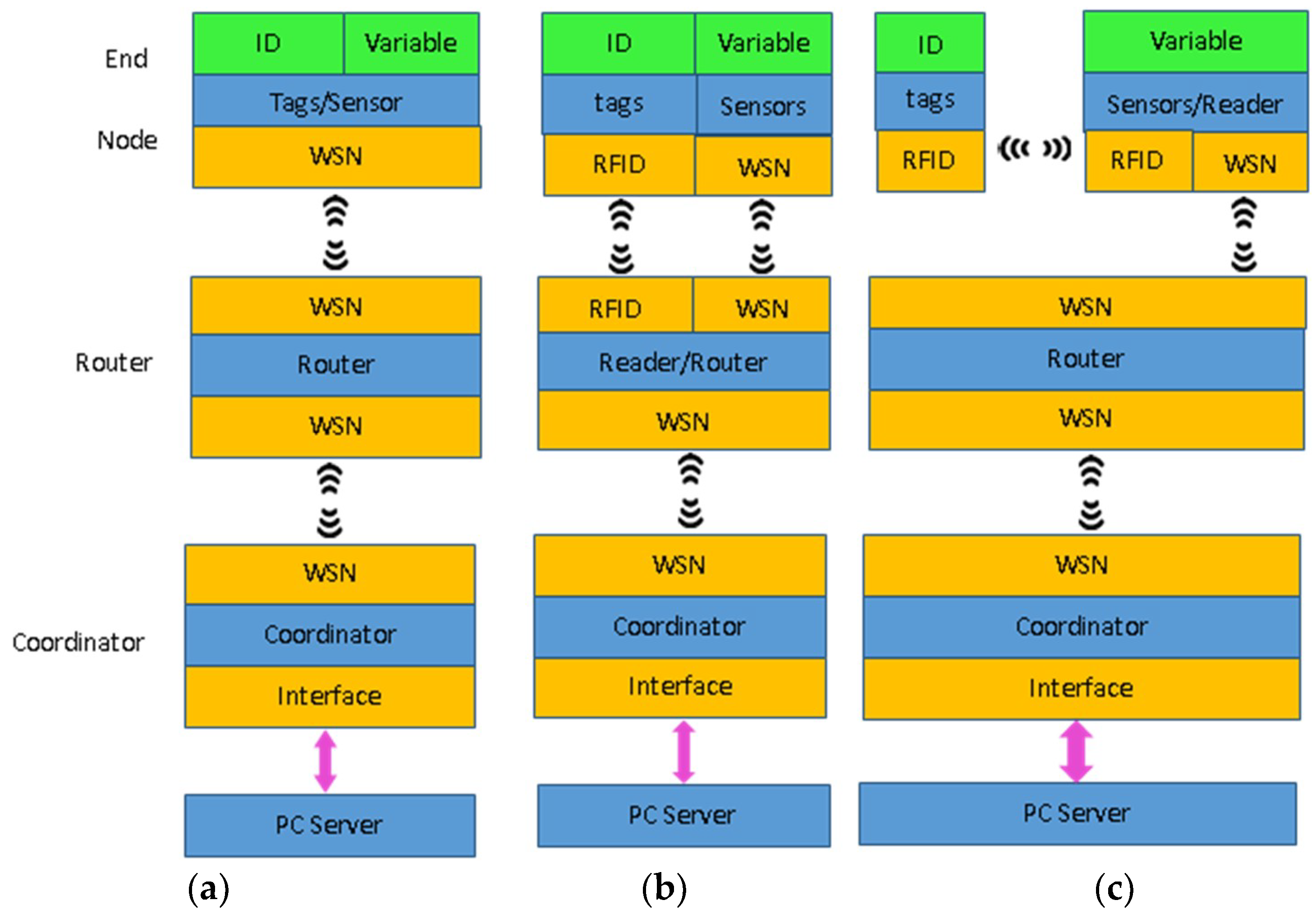
The integration of WSN and RFID involves the integration of hardware and software. In order to take advantage of WSN and RFID, the integration has three possible layouts: the integration of RFID tags with sensor nodes as shown in Figure 1a, the mixed integration architecture as shown in Figure 1b [6,7] and the integration of RFID readers with sensor nodes as shown in Figure 1c. For the first integration architecture, the end nodes can be traditional RFID tags, traditional WSN sensor nodes or a novel node that includes identification as well as more information captured by sensors [8]. For the third integration, the sensor node is equipped with a reader, which increases the power consumption of sensor nodes and pull down its efficiency [6]. For the second layouts, a smart station that incorporates RFID reader and WSN router is used so that RFID tags and sensors can coexist in the same network. The smart station is named as RFID reader/router because it works as a RFID reader as well as a WSN router [6]. The reader/router gathers both kinds of information from the end nodes and routes the information finally to the coordinator. The mixed integration uses both RF communication protocol (between RFID tags and RFID reader/router) and the ZigBee protocol (between sensor nodes and reader/router, between reader/routers). This makes the hardware and software design of the reader/router more challenging. In [9], two separate micro-controllers were used respectively for RFID reader and ZigBee router, and that led to the waste of resources and the high cost. In [10], a multi-protocol RFID reader system was implemented with a custom RFID reader board and a ZigBee mote, in addition with certain firmware. This reader can be used to construct an ad-hoc ZigBee network but not for general purpose.
The main objective of this research is to develop a portable wireless RFID reader/router for RFID-WSN hybrid system, which has long identification distance, low cost, high flexibility, scalability, and a good interactive interface. The RFID reader/router also offers the hybrid system with the capability of both identification/tracking and capture/transmitting. This design can be used in a wide range of applications.
The remainder of this paper is organized as follows. Firstly, the System architecture is introduced in Section 2. Hardware design of the RFID reader/router is described in Section 3. Section 4 presents the software design of RFID reader/router. Section 5 provides results of field test in real-world scenarios. Finally, some conclusions of this paper follow in Section 6.
2. Basic Structure of the Proposed RFID-WSN Hybrid System
The proposed RFID-WSN hybrid system is supposed to be used in applications ranging from public service and manufacturing environments to logistic organizations, in which employees, patients, products, machinery etc. are to be identified, tracked, or localized. The environment variables of a medium or large space should also be captured and transmitted to the service management control center. So both RFID tags and WSN sensor nodes are used as end nodes to cover the whole industrial or service area. The RFID reader/router is able to obtain both kinds of information from the two kinds of end nodes as well as transmit the information from one to another and finally to the coordinator.
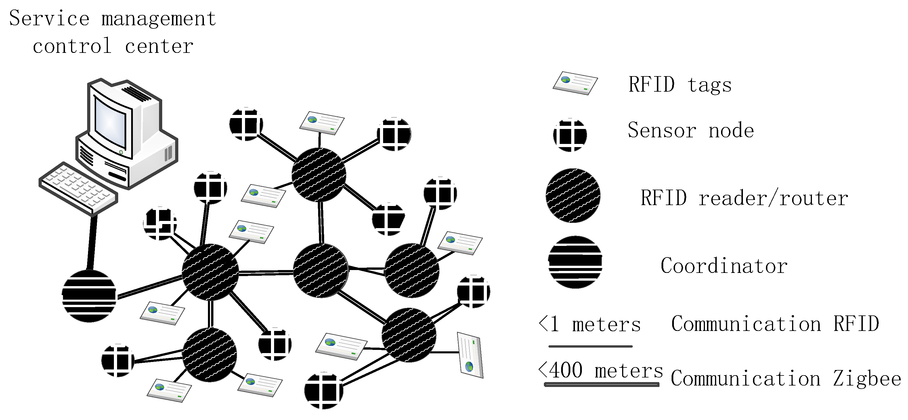
For the communication network, ZigBee is selected for its characteristics of range, auto routing capability, low power consumption and sufficient bandwidth [11]. The basic structure of the hybrid system is shown in Figure 2. The RFID reader/routers work as the receiver and transmitter of both identity and sensing information, and self-organize a network to relay the information to the coordinator and then to the service management control center.
The network communication structure of the system is shown in Figure 2, including service management control center, coordinator, RFID reader/routers, sensor nodes and RFID tags. (1) RFID tags record the label card number and data information of the item. (2) Sensor nodes are responsible for collecting the environmental information of the entire area, and then transferring the information to RFID reader/router nodes. (3) RFID reader/routers are responsible for sending information from sensor nodes to coordinator, simultaneously receiving the instruction information sent by coordinator and transferring to sensor nodes. (4) Coordinator is responsible for starting the entire ZigBee system network, sending gathered information through the serial port to the host computer application system, and simultaneously transmitting the control information that derived from the service management control center to RFID reader/routers. (5) Service management control center gathers all the identity and sensing information for further processing, and is responsible for providing human-computer interaction.
Compared with the existing RFID reader that communicates with the host computer through RS232 or Ethernet interface, the RFID reader/routers offer two wireless communication links. The RFID reader part works at 13.56 MHz with passive RFID tags. The router part works at 2.4 GHz with sensor nodes, other RFID reader/routers and the coordinator.
The hybrid system has the following benefits: (1) The communication range for 13.56 MHz passive RFID tags is enlarged; and (2) keeps the simplicity of the sensor node. There is no additional power consumption for sensor nodes; (3) sensor nodes, coordinator and RFID reader/routers can communicate with each other by creating a robust self-organizing networks.
3. Hardware Design of RFID Reader/Router
3.1. Hardware Composition of RFID Reader/Router
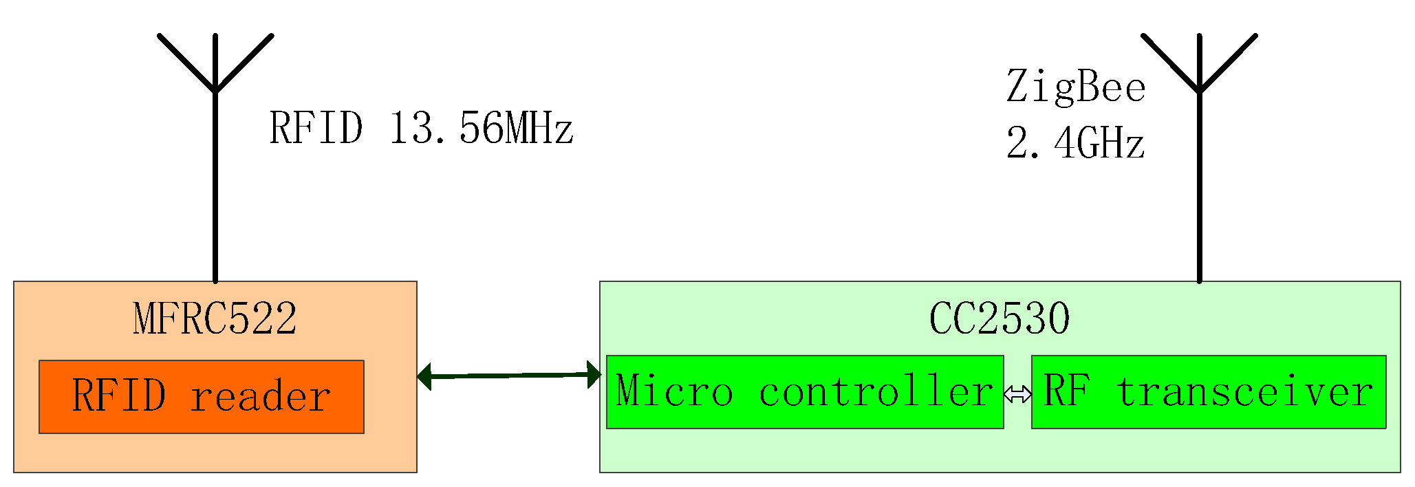
The block diagram of the RFID reader/router is shown In Figure 3. CC2530 works as the microprocessor and the 2.4 GHz transceiver. It gets environmental information, and transmits information to the coordinator in the WSN network. It also executes the commands sent by the coordinator. MFRC522 operates at 13.56 GHz as a RFID reader. It performs read and write operations. At the respective operating frequencies, CC2530 and MFRC 522 do not interfere with each other.
3.2. Hardware Design of Wireless RFID Reader/Router
3.2.1. Circuit Design of Radio Frequency (RF) Module
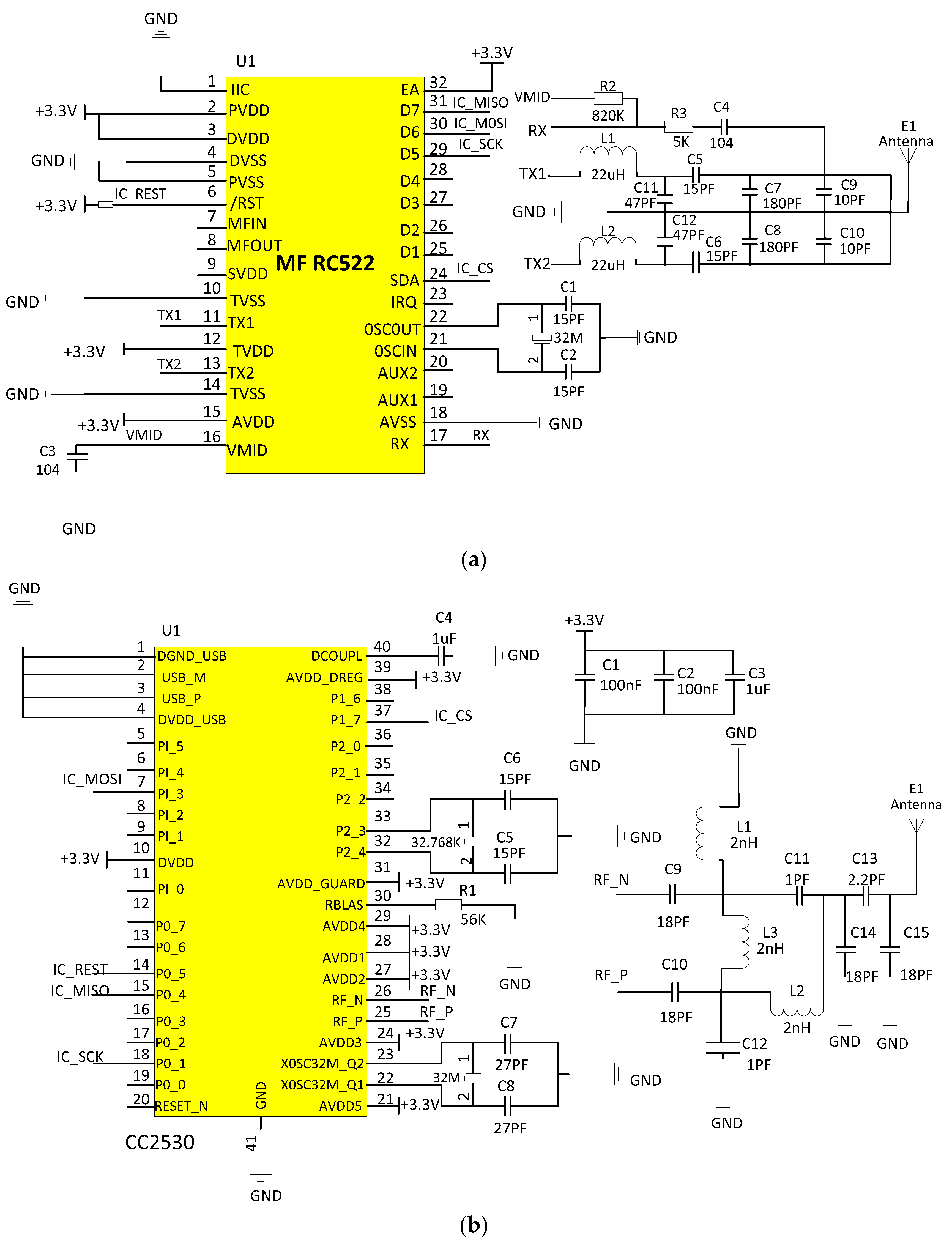
RF communication circuit consists of micro controller and RF chip. Its main function is to communicate with the electronic tags for completing the exchange of the tag information. The core chip of RF module is Philips MF RC522. Electronic tags are M1 cards produced by Philips. Figure 4a shows the RF communication module circuit.
As shown in Figure 4a, the RF module transmits carrier energy signal which is 13.56 MHz and modulated by envelope signal to the antenna module through pins TX1 and TX2. The antenna is driven by an Electro Magnetic Compatibility (EMC) filter circuit consisted of L1, L2, C11, and C12, and a matching circuit composed of C5–C10. In the receiving circuit, the DC input voltage of the RX pin is stabilized at the pin VMID by C3 and R2, and its AC input voltage can be adjusted by R3 and C4.
3.2.2. Circuit Design of ZigBee Sensor Nodes
ZigBee sensor node primarily controls the data exchange between RF module and electronic tags. The system uses CC2530 low-power RF chip which is made by TI/Chipcon. It integrates the IEEE 802.15.4/ZigBee RF transceiver and industrial standard enhanced 8051 Micro Controller Unit (MCU) kernel, the core of the control circuit is shown in Figure 4b.
Data read operation: The mainframe sends the highest bit 1 and pulls IC_CS low at the same time. The 8-bit address of the read data is encoded in the prescribed format, and the data is sent to the MOSI line from high to low after 8 cycles. After receiving a data of reading instruction address, the corresponding data will be sent back to the mainframe by MF RC522. The mainframe will read out the data on MISO after eight cycles and store on a temporary variable, pull IC_CS up at the same time. That indicates the completing of reading operation of one byte.
Data write operation: The mainframe sends the highest bit 0, and pulls IC_CS low at the same time. According to the way of sending address in read data operation, the target address is sent out after eight cycles. Then the written data is sent out through MOSI after another eight cycles. That indicates the completing of the corresponding address update in MF RC522.
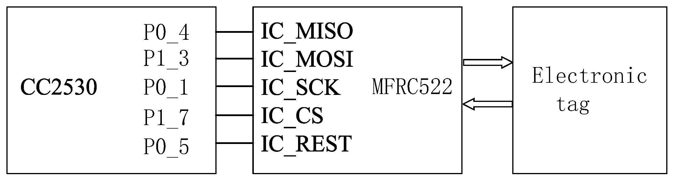
The system uses 32 MHz crystal oscillator clock signal as the core controller, and Serial Peripheral Interface (SPI) way of communication is used between the CC2530 and RF module. P1_7 connects SDA end of RF chip MF RC522 that is used as a signal of the control line. P0_1, P1_3 and P0_4 connect respectively the RF chip MF RC522 D5, D6 and D7, registers associated with MF RC522 are controlled to read and write by SPI mode. P0_5 connects reset pin of MF RC522 for resetting the controller. Figure 5 shows I/O interface connection of CC2530 and MF RC522.
3.2.3. Circuit Design of ZigBee Coordinator
The role of ZigBee coordinator is sending ZigBee terminal nodes’ information to the host computer through the serial port, and at the same time, sending control instructions from the host computer to the terminal nodes through wireless network. Because TTL level is adopted in CC2530 and EIA level in host computer communication, level translation is needed for effective data communications. MAX232 chip is used to achieve the translation between the two electrical levels. The circuit of ZigBee coordinator is shown in Figure 4b. It is consistent with the terminal node circuits and is set as the coordinator in the Z-stack protocol stack only.
4. Software Design of RFID Reader System
4.1. Main System Flow Chart
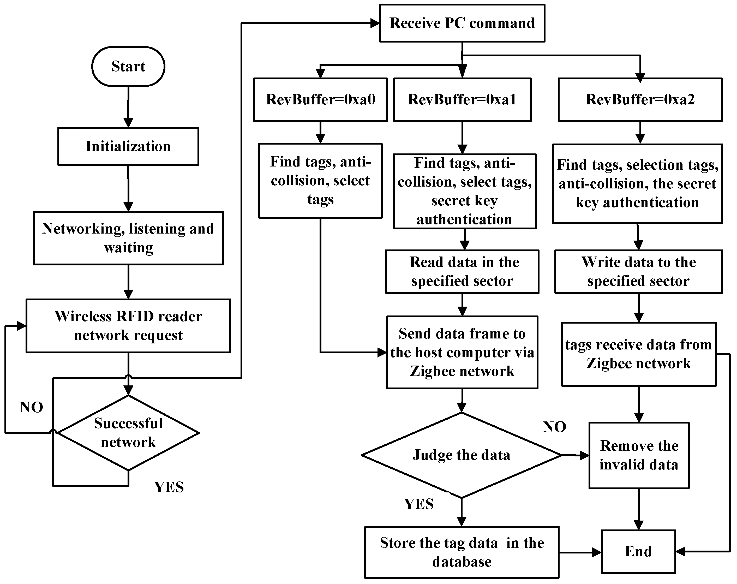
Throughout the system, ZigBee coordinator forms entire ZigBee communication network, and waits for router nodes and sensor nodes to join it. During network operation RFID reader collects related node information, then sends it to the host computer through ZigBee network, and finally stores related information into the database. The main system flow chart is shown in Figure 6.
In RFID reader/router, RF chip MF RC522 communicates with electronic tags following the communication protocol of ISO/IEC14443A. Through SPI (Serial Peripheral Interface), CC2530 controls communication between MF RC522 and type matched cards within the range of the antenna. It then reads information in card and deals with the information accordingly to make it compliant with the ZigBee protocol packets [15,16]. It sends the packets to the coordinator in ZigBee network following IEEE 802.15.4. The coordinator connects with the host computer via the UART interface, and ultimately sends the data to host computer for processing. Similarly, the host computer can send control commands to operate the electronic tag, such as modification of the information.
4.2. Design of Communication Protocol for RFID Reader System
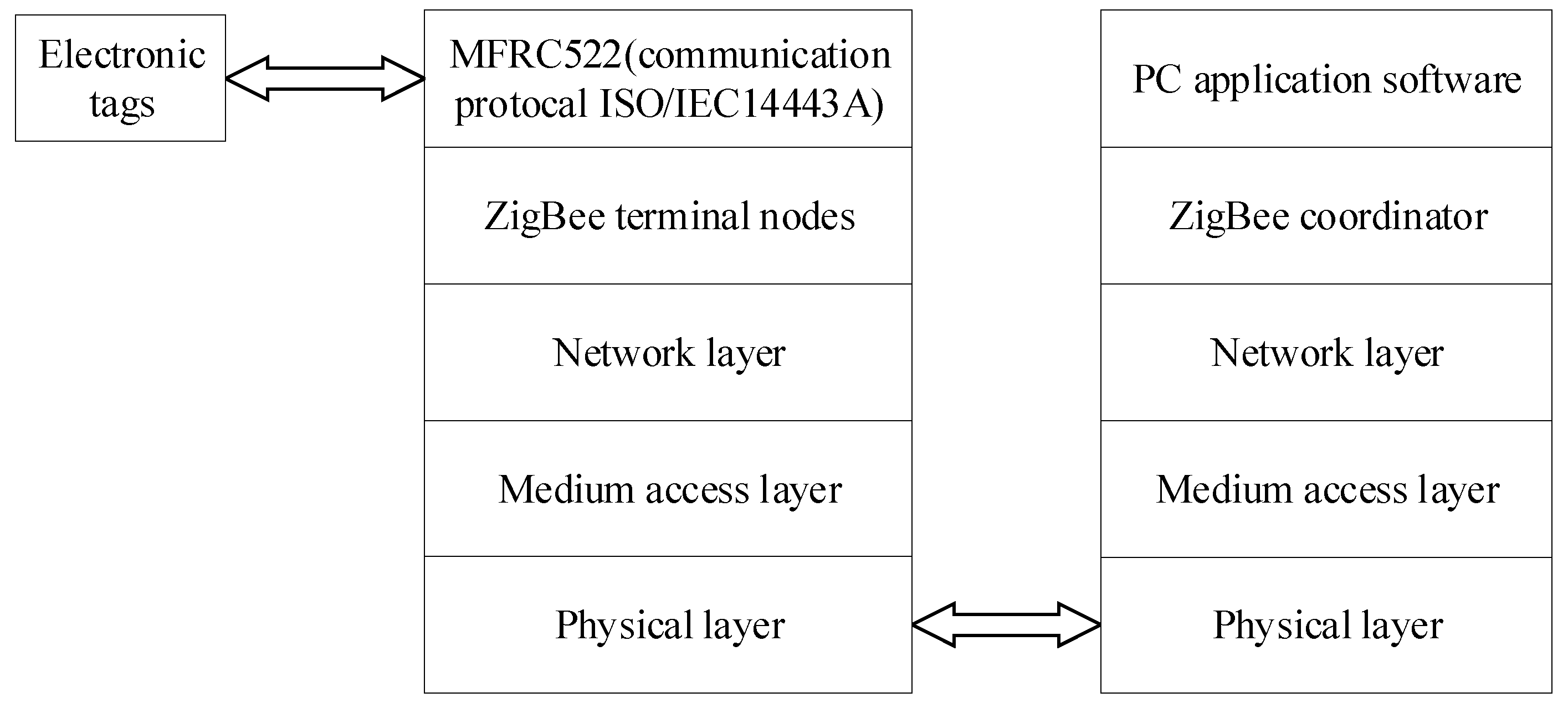
In the whole system, ZigBee terminal node controls MF RC522 RF card collection of data, and then transmits to other wireless or wired network through the ZigBee protocol transmission. The system communication protocol frame is shown in Figure 7.
In the RFID reader system, the communication protocol between RF chip of MF RC522 and electronic tags follows ISO/IEC 14443A. The master chip controls the communication between MF RC522 and electronic tag whose type is consistent with the range type of the antenna through the SPI interface. It reads the electronic tag information and processes the information to packets according to ZigBee protocol [16]. It then sends the data packet to the ZigBee coordinator. The communication protocol between them is IEEE 802.15.4. Coordinator connects with the host computer through the UART and eventually transmits data to the host computer for processing. It can also modify the electronic tags information through the host computer sending control instructions.
4.3. Design of RFID Reader Software System
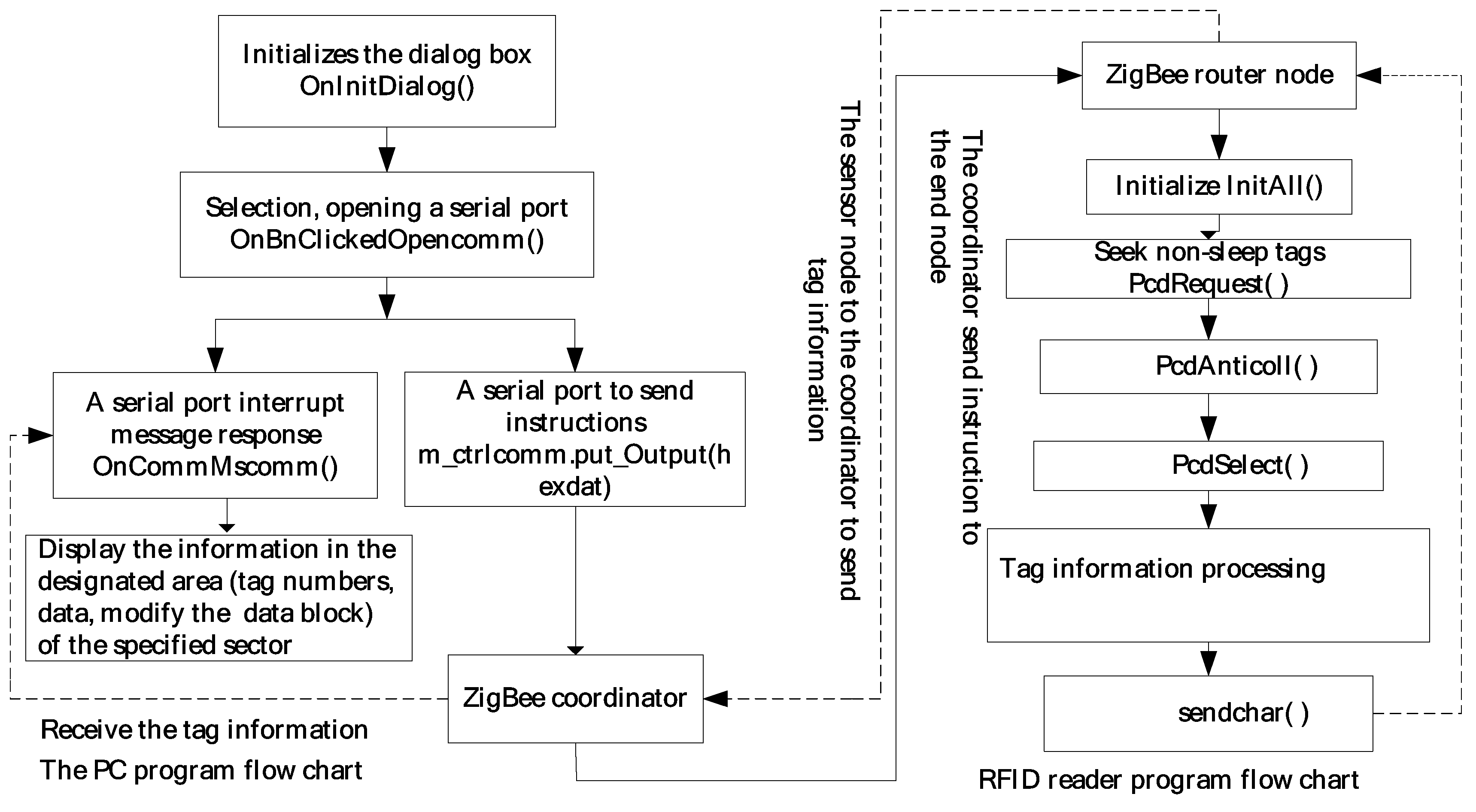
On the VS2008 platform, the host computer reader software based on serial communication is developed. The serial communication control MSCOMM in Microsoft Foundation Classes (MFC) is used to set the serial number, baud rate, parity bit and stop bit of serial. The application software can realize the function of reading the electronic tag number, reading the data block of the specified sector, and modifying the data block of the specified sector. The flow chart of the communication function between RFID reader and host computer is demonstrated in Figure 8.
The host computer application software sends control instructions to the ZigBee coordinator through the host computer serial port, and the coordinator transmits the control instructions to ZigBee router nodes. Router nodes core controller CC2530 determines inside procedures according to the control commands, and then controls registers in RF chip MF RC522, and sends out the corresponding coded instructions through an antenna. Electronic tags within the range of reader perform operations according to the commands, and then return the appropriate data to the reader. ZigBee router nodes parse out the data returned from the electronic tag and send the electronic tag information to the ZigBee coordinator. Then the coordinator transmits information through UART serial port to the host computer software and the data is displayed on the software interface. Its basic program flow is shown in Figure 9.
4.4. Application Software Design of Host Computer
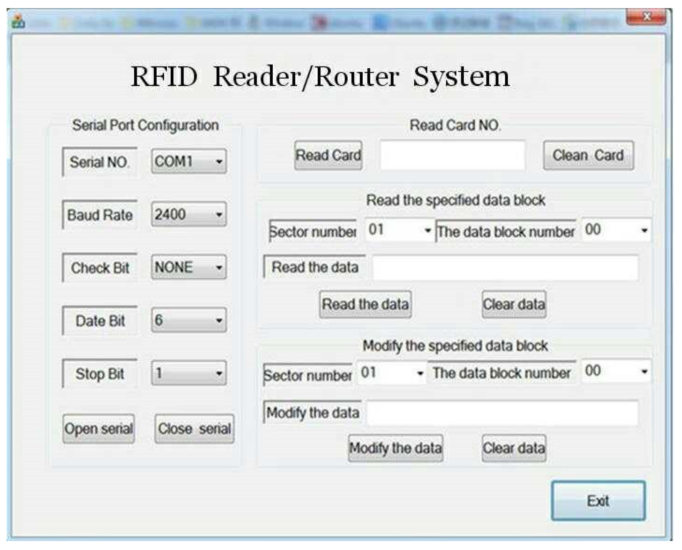
A reader software for host computer based on serial communication is developed on Visual Studio 2008 development platform. With this application software, data in specified block of the tags and sensors are read or modified. The application software for host computer is shown in Figure 10.
The process of writing tags from the host computer is explained through an example, in which the user modifies the data block 00 in sector 01. In the “Modify the specified data block”, the “Sector number” is “01”, the “The data block number” is “00” and the “Modify the data” is “01888888882510199990000251110088”. Then the “Modify the data” button is clicked, and the data is encoded as “19A2FFFFFFFFFFFF0401888888882510199990000251110088” by the host computer system. Every two numbers takes up one byte, and “19” represents 25 bytes sending to the reader, “A2” indicates the data writing instruction to be executed, “FFFFFFFFFFFF” is the initial cryptographic of data block, “04” represents the fourth block of data block. The host computer software encodes the control instructions string encoding into binary format data that will be send to the ZigBee coordinator through the serial port of host computer and ZigBee terminal node through the coordinator. Terminal node controls RF chip MF RC522 and stores the data in the corresponding data block of electronic tags. In order to verify whether the data is correct or not, the data written into is read out by clicking “Read the specified data block” to check. As shown in above Figure 7, the “Sector number” is “01” and the “The data block number” is “00”. Then the “Read the data” button is clicked and the data just written is shown in “Read the data” box.
5. Communication Systems of Integrated ZigBee and RFID Technology
5.1. Communication System Hardware
Hardware of communication systems of integrated ZigBee and RFID technology includes ZigBee coordinator, RFID reader/router, ZigBee sensor node, and RFID tags, as shown in Figure 11.
Because of the low power consumption of the ZigBee technology, all modules in Figure 11 are powered by dry battery. The ZigBee coordinator transmits data with host computer by USB. RFID reader/routers are responsible for collection of information and forwarding instruction of RFID reader. ZigBee sensor nodes are responsible for controlling the RF module to read, write and modify the relevant data in electronic tag.
5.2. Performance Testing of Communication System
The reliability of a communication system consisting of a coordinator, router node (RFID reader/router), a ZigBee sensor node and three electronic tags was tested. The test was carried out under the environment that ambient temperature is 28 °C and ZigBee node emission power is 4.5 dBm.
The test is conducted in two cases: (1) outdoor test: open field without obstacles (2) indoor test: router nodes are placed in the laboratory, and coordinators are placed in corridor outside the laboratory. The shape of the corridor is rectangle with right corner. The corridor locates on the second floor of a building. The thickness of the concrete wall of the corridor is 26cm. The host computer sends instructions of reading (or writing) tag to the reader, then the corresponding router performs command of reading (or writing) to operate the electronic tag. The packet loss rate can be calculated after counting the times of router fail to execute the instructions of coordinator correctly or the times of information error after executing the instructions. During the test, the distance between the coordinator and the router nodes changes constantly to verify the impact of different test distances on the reading (or writing) results during the test. The maximum distance of the tag reading is 10 cm.
The test results are shown in Table 1. In outdoor test, when the transmission distance between the coordinator and router (RFID reader/router) is in the range of 80–100 m the maximum packet loss rate is 3%; when the test distance is 80 m or less, the packet loss rate is 0. In indoor test, when the transmission distance is 30–50 m and the maximum packet loss rate is 3%. When the test distance is 30 m or less, the packet loss rate is 0. The test results show that the system can achieve stable data transmission. I also prove that the wireless communication between the ZigBee coordinator and the ZigBee router increases the transmission distance of the reader system.
6. Conclusion
In this paper, we combine RFID technology with ZigBee technology to design both the hardware system and software application of RFID reader/router based on MFRC522 and CC2530. implemented RFID reader/router realizes bidirectional transmission of communication data and makes system networking more flexible. Because the network has router nodes, it can avoid the problem of energy imbalance in networks. At the same time, the system has a good scalability and terminal nodes are small, cheap, and easy to deploy. The RFID reader/router developed could be used in the existing network according to the application requirement, so that a bigger wireless sensor network is achieved. In indoor and outdoor environments, the reliability of the wireless RFID reader/router is tested. The packet loss rate is less than 3% through a transmission distance of 80–100 m outdoors and 30–50 m indoors. The system overcomes many shortcomings of the traditional RFID reader, such as short distance, poor anti-interference, susceptibility to environmental impacts.
Meanwhile, CC2530 chip is adopted in the system as the micro controller to control the data transmission, and control reading and writing operations of the RF module on electronic tags. This not only overcomes the drawback of high cost in using two kinds of micro controller, but also eliminates the hassle of wiring and saves energy. Experiment shows that the system has a high stability, a long identification distance, an applicable flexibility and a good scalability. It is of significant economical and practical value.
Author Contributions
Wusheng Ji wrote the manuscript; Wusheng Ji and Weiwei Zhou provided relevant information, discussed the data, and corrected the manuscript; and Li Li revised the manuscript. All authors have read and approved the final manuscript.
Acknowledgments
This work was supported by Science and Technology Correspondent Research Program of Tianjin Municipal Science and Technology Commission in 2016, China, under Grant 16JCTPJC52500.
Conflicts of Interest
The authors declare no conflicts of interest.
References
- Mejjaouli, S.; Babiceanu, R.R. RFID-wireless sensor networks integration: Decision models and optimization of logistics systems operations. J. Manuf. Syst. 2015, 35, 234–245. [Google Scholar] [CrossRef]
- Zhang, B.; Hu, K.; Zhu, Y. Network architecture and energy analysis of the integration of RFID and Wireless Sensor Network. In Proceedings of the 2010 Chinese Control and Decision Conference, Xuzhou, China, 26–28 May 2010; pp. 1379–1382. [Google Scholar]
- Torres, B.; Pang, Q.; Skelton, G.W.; Bridges, S.; Meghanathan, N. Integration of an RFID reader to a wireless sensor network and using it to identify an individual carrying RFID tags. Int. J. Ad hoc Sens. Ubiquitous Comput. 2010, 1, 15. [Google Scholar]
- Ansola, P.G.; García, A.; Morenas, J.D.L.; Escribano, J.G.; Otamendi, F.J. Zigid: Improving visibility in industrial environments by combining WSN and RFID. J. Zhejiang Univ. Sci. A Appl. Phys. Eng. 2011, 12, 849–859. [Google Scholar] [CrossRef]
- Medagliani, P.; Ferrari, G.; Marastoni, M. Hybrid Zigbee-RFID networks for energy saving and lifetime maximization. Remote Instrum. Virtual Lab. 2010, 7, 473–491. [Google Scholar]
- Adame, T.; Bel, A.; Carreras, A.; Melià-Seguí, J.; Oliver, M.; Pous, R. Cuidats: An RFID–WSN hybrid monitoring system for smart health care environments. Futur. Gener. Comput. Syst. 2016, 78, 602–615. [Google Scholar] [CrossRef]
- Al-Turjman, F.M.; Al-Fagih, A.E.; Hassanein, H.S. A novel cost-effective architecture and deployment strategy for integrated rfid and wsn systems. In Proceedings of the International Conference on Computing, Networking and Communications, San Diego, CA, USA, 28–31 January 2013; pp. 835–839. [Google Scholar]
- Deng, H.; Varanasi, M.; Swigger, K.; Garcia, O.; Ogan, R.; Kougianos, E. Design of sensor-embedded radio frequency identification (SE-RFID) systems. In Proceedings of the IEEE International Conference on Mechatronics and Automation, Luoyang, China, 25–28 June 2006; pp. 792–796. [Google Scholar]
- Yang, L.; Xu, M. The hardware design of frequency identification system based on zigbee technology. J. Harbin Inst. Technol. Univ. 2012, 17, 65–68. [Google Scholar]
- Lewis, M.P.; Hsu, K.W. TelosRFID: An ad-hoc wireless networking capable multi-protocol RFID reader system. In Proceedings of the Radio and Wireless Symposium, New Orleans, LA, USA, 10–14 January 2010; pp. 392–395. [Google Scholar]
- Abad, E.; Palacio, F.; Nuin, M.; González de Zárate, A.; Juarros, A.; Gómez, J.M.; Marco, S. RFID smart tag for traceability and cold chain monitoring of foods: Demonstration in an intercontinental fresh fish logistic chain. J. Food Eng. 2009, 93, 394–399. [Google Scholar] [CrossRef]
- Wang, L.; Xu, L.; Bi, Z.; Xu, Y. Data cleaning for RFID and WSN integration. IEEE Trans. Ind. Inf. 2013, 10, 408–418. [Google Scholar] [CrossRef]
- Li, H.S.; Bian, G.R.; He, N.H. Network Design and Implementation of Intelligent Warehouse Based on EPC/RFID and WSN. Appl. Mech. Mater. 2012, 236, 338–343. [Google Scholar] [CrossRef]
- Liu, H.; Bolic, M.; Nayak, A. Taxonomy and challenges of the integration of rfid and wireless sensor networks. IEEE Netw. 2008, 22, 26–35. [Google Scholar] [CrossRef]
- Texas Instruments. CC2420 2.4GHz IEEE802.15.4/ZigBee-ready RF transceiver. Available online: http://www.ti.com/lit/ds/symlink/cc2420.pdf (accessed on 3 November 2018).
- Freescale Semiconductor. MC13192 2.4GHz low power transceiver for the IEEE 802.15.4 standard. Available online: https://www.digchip.com/datasheets/download_datasheet.php?id=1625603&part-number=MC13192 (accessed on 3 November 2018).
Figure 1.
The integration structure of Radio Frequency Identification (RFID) and Wireless Sensor Network (WSN) (a) Integration of RFID tags with sensor nodes; (b) Integration of RFID readers with sensor nodes; (c) Mixed integration.
Figure 1.
The integration structure of Radio Frequency Identification (RFID) and Wireless Sensor Network (WSN) (a) Integration of RFID tags with sensor nodes; (b) Integration of RFID readers with sensor nodes; (c) Mixed integration.

Figure 2.
Communication structure of the proposed hybrid system.

Figure 3.
Block diagram of the RFID reader/router.

Figure 4.
Schematic of the RFID reader/router (a) RFID reader system communication module and (b) ZigBee core control circuit.
Figure 4.
Schematic of the RFID reader/router (a) RFID reader system communication module and (b) ZigBee core control circuit.

Figure 5.
The I/O port circuit between CC2530 and MF RC522.

Figure 6.
System main program flow chart.

Figure 7.
System communication protocol architecture.

Figure 8.
The flow chart of the communication function between RFID reader and host computer.

Figure 9.
The communication flow chart of RFID reader and host computer.

Figure 10.
RFID reader/router application software.

Figure 11.
Hardware for integrated RFID and wireless sensor networks.


Table 1.
The test results of transmission distance between the ZigBee sensor node and the RFID reader/router node.
Table 1.
The test results of transmission distance between the ZigBee sensor node and the RFID reader/router node.
| Test Number | Test Environment | Test Distance | Number of Tests for Commands (Read, Write) | Number of Received Commands (Read, Write) | Packet Loss Rate |
|---|---|---|---|---|---|
| 1 | indoor | 30 m | 50, 50 | 50, 50 | 0 |
| 2 | indoor | 40 m | 50, 50 | 49, 50 | 1% |
| 3 | indoor | 50 m | 50, 50 | 48, 49 | 3% |
| 4 | indoor | 55 m | 50, 50 | 45, 43 | 12% |
| 5 | outdoor | 80 m | 50, 50 | 50, 50 | 0 |
| 6 | outdoor | 90 m | 50, 50 | 50, 49 | 1% |
| 7 | outdoor | 100 m | 50, 50 | 49, 48 | 3% |
| 8 | outdoor | 105 m | 50, 50 | 44, 43 | 13% |
© 2018 by the authors. Licensee MDPI, Basel, Switzerland. This article is an open access article distributed under the terms and conditions of the Creative Commons Attribution (CC BY) license (http://creativecommons.org/licenses/by/4.0/).
Share and Cite
MDPI and ACS Style
Ji, W.; Li, L.; Zhou, W. Design and Implementation of a RFID Reader/Router in RFID-WSN Hybrid System. Future Internet 2018, 10, 106. https://doi.org/10.3390/fi10110106
AMA Style
Ji W, Li L, Zhou W. Design and Implementation of a RFID Reader/Router in RFID-WSN Hybrid System. Future Internet. 2018; 10(11):106. https://doi.org/10.3390/fi10110106
Chicago/Turabian StyleJi, Wusheng, Li Li, and Weiwei Zhou. 2018. "Design and Implementation of a RFID Reader/Router in RFID-WSN Hybrid System" Future Internet 10, no. 11: 106. https://doi.org/10.3390/fi10110106
Note that from the first issue of 2016, this journal uses article numbers instead of page numbers. See further details here.