Real-Time Tumor Motion Tracking in 3D Using Planning 4D CT Images during Image-Guided Radiation Therapy


1
Division of Mechanical and Biomedical Engineering, College of Engineering, Ewha Womans University, Seoul 03760, Korea
2
Bio-Medical IT Convergence Research Department, Electronics and Telecommunications Research Institute, Daejeon 34129, Korea
*
Author to whom correspondence should be addressed.
Algorithms 2018, 11(10), 155; https://doi.org/10.3390/a11100155
Submission received: 9 September 2018
/
Revised: 5 October 2018
/
Accepted: 7 October 2018
/
Published: 11 October 2018
Abstract
:In this paper we propose a novel method for tracking the respiratory phase and 3D tumor position in real time during treatment. The method uses planning four-dimensional (4D) computed tomography (CT) obtained through the respiratory phase, and a kV projection taken during treatment. First, digitally rendered radiographs (DRRs) are generated from the 4DCT, and the structural similarity (SSIM) between the DRRs and the kV projection is computed to determine the current respiratory phase and magnitude. The 3D position of the tumor corresponding to the phase and magnitude is estimated using non-rigid registration by utilizing the tumor path segmented in the 4DCT. This method is evaluated using data from six patients with lung cancer and dynamic diaphragm phantom data. The method performs well irrespective of the gantry angle used, i.e., a respiration phase tracking accuracy of 97.2 ± 2.5%, and tumor tracking error in 3D of 0.9 ± 0.4 mm. The phantom study reveals that the DRRs match the actual projections well. The time taken to track the tumor is 400 ± 53 ms. This study demonstrated the feasibility of a technique used to track the respiratory phase and 3D tumor position in real time using kV fluoroscopy acquired from arbitrary angles around the freely breathing patient.
1. Introduction
Tracking lung tumors accurately in real time in a three-dimensional (3D) space is particularly important for image-guided radiation therapy for lung cancer patients. Unless accurate tumor tracking is achieved, not only is it challenging to provide a sufficient dose escalation to the tumor, complications arise by emitting excessive doses to healthy tissue surrounding the tumor [1,2,3,4]. The main cause of uncertainties in tumor tracking is movement of the internal organs due to the patient’s respiration [5,6].
A number of techniques have been explored to reduce such tumor-tracking uncertainty. External respiratory surrogates are actively being used to indirectly track the tumor location, which include reflective landmarks placed on the abdominal surface of the patient [7,8,9], a strain gauge-based pressure-sensing belt [10,11], and optical abdominal surface imaging [12,13,14]. These surrogates are advantageous in that they are non-invasive and require no additional radiation dose to the patients. However, these external signals may not accurately reflect the movement of the tumor within the human body [15], and the signals may differ depending on how the external signal equipment is installed, thereby degrading the repeatability of the signals [16]. On the other hand, a method for tracking a fiducial marker [17,18], or using an electromagnetic transponder [19,20] implanted in or around the tumor, has been developed, which has excellent tracking accuracy owing to its direct tumor tracking. However, patients may feel uncomfortable during such an invasive surgical procedure for implant placement. Several fiducial-less methods also have been proposed and track tumor or respiratory motion successfully; however, the techniques can be applied using a separate dedicated tracking system (e.g., multiple X-ray cameras [21], Xsight lung tracking system [22], 4D ultrasound imaging [23]).
For non-invasive and direct tumor tracking, studies using an on-board kV fluoroscopy system have been reported [6,24,25,26,27]. When the tumors shown through the fluoroscopy have an adequately high contrast, such methods can yield good results. However, because it is difficult to obtain high-contrast tumors through fluoroscopic means, these methods have been tested on images acquired from the anterior–posterior direction, where there is relatively little overlap with other organs. These methods, which only work in a specific direction of rotation, are not suitable for rotational cone-beam systems. In addition, because the tumor location is tracked by relying on 2D fluoroscopy, there is no resolution information in the direction of the radiation direction, i.e., the depth direction, making it impossible to trace the full 3D tumor location [6].
To track the complete six degrees-of-freedom (DOF) tumor movement, 2D/3D registration using megavoltage (MV) fluoroscopy [5] or templates containing tumor movements according to the respiratory phase [28] have been used. An MV fluoroscopy technique has a disadvantage in that separate MV images have to be acquired and synchronized with kV images. In addition, this method has been tested only at certain angles of the gantry, and it does not guarantee a good level of performance with kV images obtained in the left–right direction where the tumor overlaps with other organs. A template-based method should approximate the tumor location at the gantry angles where the tumor is not visible owing to an overlap with other objects using the surrounding gantry angle data where the tumor is visible, which results in a degraded performance at certain gantry angles.
To avoid excessive radiation uptake of healthy tissue, the radiotherapy system should accurately irradiate the tumor to the treatment beam at various angles while rotating around the freely breathing patient. In response to this need, in this study we propose a method for tracking the respiratory phase and 3D tumor position in real time during treatment using a kV image mounted on the treatment system. Using data on six lung tumor patients and a dynamic phantom, the performance of the proposed method was evaluated at 360 degrees around the patient, including the gantry angles at which the contrast of the diaphragm or tumor was low.
2. Materials and Methods
2.1. Pipelines for Respiratory Phase Identification
2.1.1. Pre-processing of Planning and Treatment Images
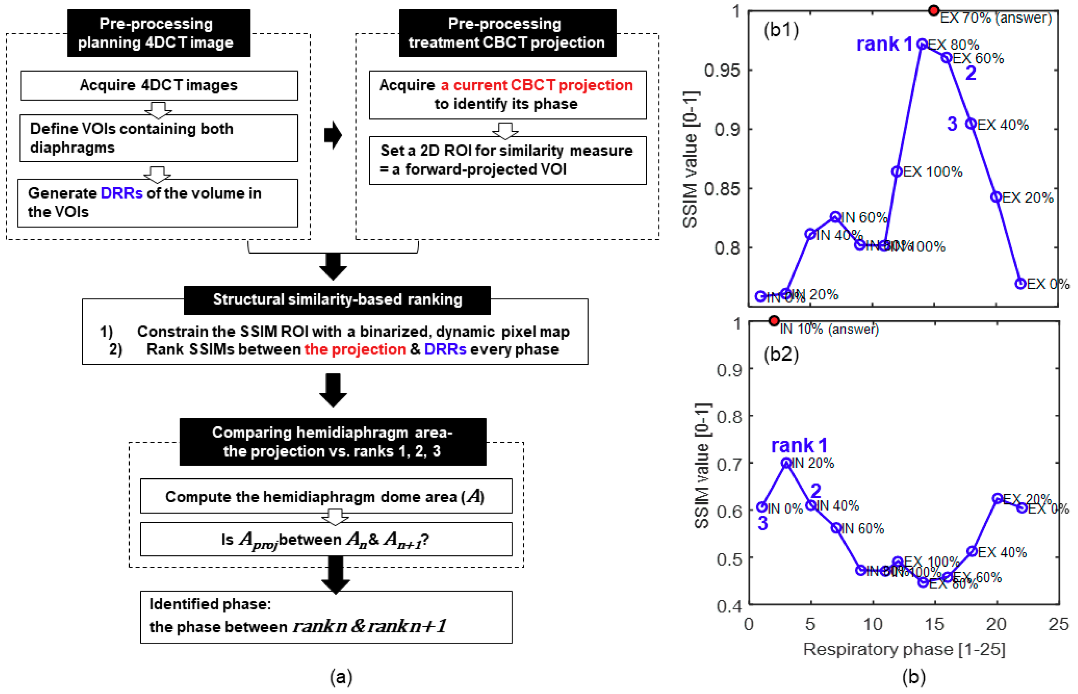
The proposed method utilizes respiration-correlated, four-dimensional (4D) computed tomography (CT) images (i.e., planning 4DCT) at every 10% of the respiratory cycle obtained for treatment planning in advance, as shown in Figure 1. Planning 4DCT consists of a set of three-dimensional (3D) CT images, each of which corresponds to one of the respiratory phases. The cubic volume of interest (VOI) covering the entire range of movement of the diaphragm on both sides was defined in the planning 4DCT. Then, digitally rendered radiographs (DRR, i.e., a simulated projection) were generated from planning 4DCT in the VOI for all respiratory phases at all gantry angles of two-dimensional (2D) cone beam CT (i.e., treatment CBCT) projections in image-guided radiotherapy (IGRT). Here, a CBCT projection is a single kV image acquired from a gantry-mounted on-board an X-ray imaging system.
Moreover, a single volume of treatment CBCT in IGRT was acquired at the beginning of the treatment session. The geometries of the planning 4DCT and treatment CBCT in IGRT were rigidly registered using static anatomical bone structures. The predefined VOI in the planning 4DCT was forward-projected onto 2D DRRs and treatment CBCT projections to define the 2D regions of interest (ROI) for the following steps.
2.1.2. Structural Similarity-Based Ranking
To identify the respiratory phase of the treatment CBCT projection of interest, the structural similarity (SSIM) index [29] was computed between the planning DRRs of all phases and the treatment CBCT projection. SSIM quantifies the amount of degradation of structural information in an image (planning DRRs) as compared to a reference image (i.e., treatment CBCT projection). Because planning DRR with a higher SSIM is more likely to have a similar phase as that of the treatment CBCT projection, the SSIM value of every DRR was ranked.
First, the ROI for the SSIM computation was constrained to pixel-wise regions influenced by the diaphragm motion within the predefined 2D ROI, where the variation in pixel intensity over the respiratory phases is large relative to the mean of all phases, as shown in Equation (1). The pixel-wise regions with a variation larger than threshold θ were selected to produce a binary motion mask that functioned as the SSIM ROI, and threshold θ was set using Otsu’s threshold method [30]:
where is the intensity of a pixel (u, v) on the detector; i and N represent the respiratory phase index and total number of respiratory phases, respectively; and . Then, the SSIM values between the normalized CBCT projection and all of the normalized DRRs were computed over the SSIM ROI, and the DRRs with SSIM ranks of 1, 2, and 3 were identified. Figure 1b shows the representative SSIM rank profiles over the respiratory phases. As shown in Figure 1(b1), the phase between ranks 1 and 2 is usually the correct phase. However, when the difference in SSIM between ranks 2 and 3 is insignificant, this is not always true (see Figure 1(b2)). Thus, we add one more step to achieve the following.
2.1.3. Comparing Hemidiaphragm Area Ranking
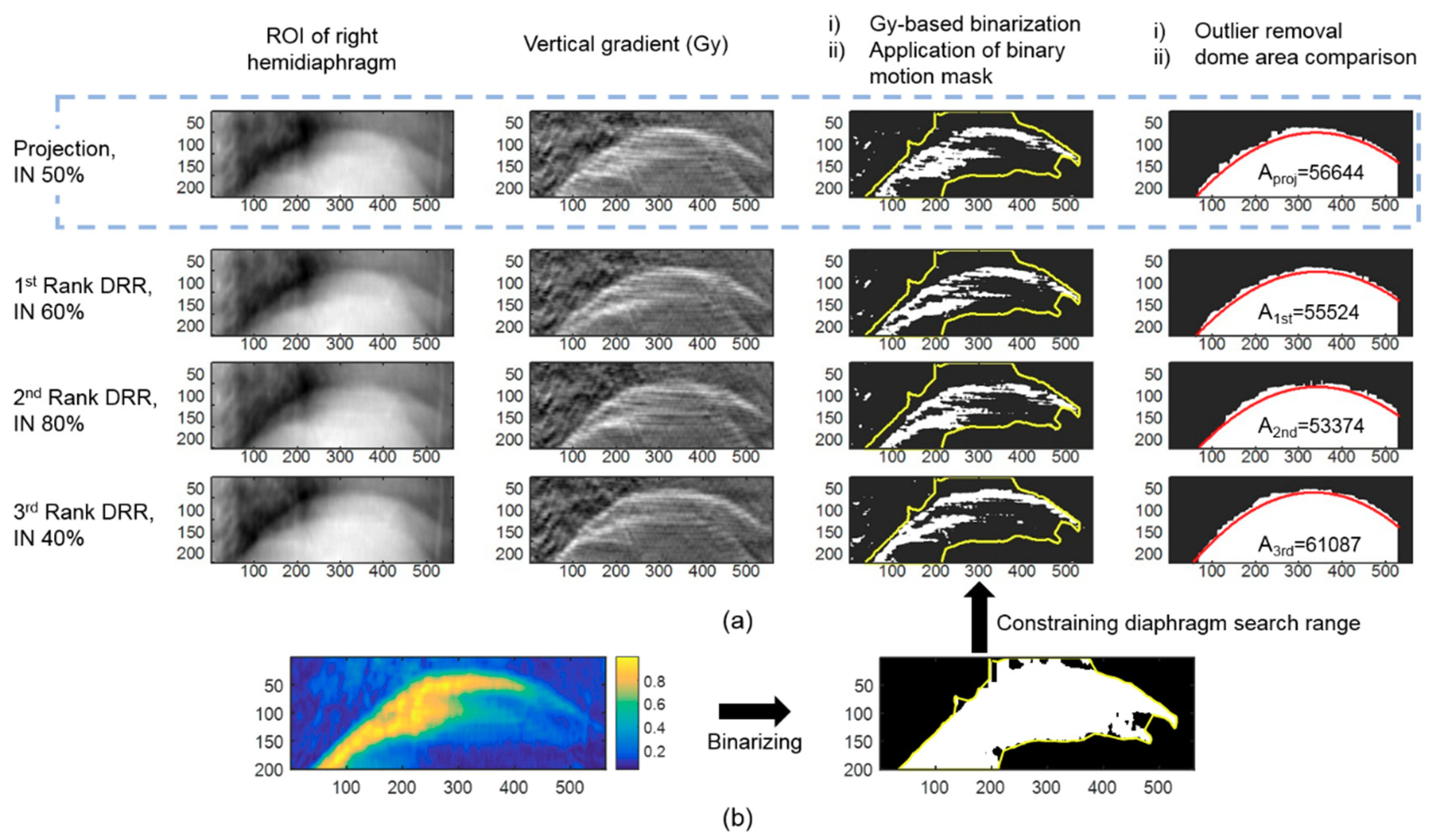
The hemidiaphragm dome area on the projections of ranks 1, 2, and 3 was computed. When the area on the current projection (Aproj) is between ranks n (An) and n + 1 (An+1), the correct phase is determined to be between ranks n and n + 1. The following steps were used to calculate the area under the diaphragm dome on the projection image (see Figure 2). First, a vertical gradient was applied in the Y-axis direction on the ROI of the right hemidiaphragm, and the image was binarized based on the pixel-wise gradient intensity (Gy). Next, after defining a binary motion mask using Equation (1) in the manner described above, the search range for finding the diaphragm outline shape was limited to the motion mask obtained. Then, a second-order polynomial fit was applied to the data points within the search range. When the Euclidean distance of a point from the polynomial fit was greater than twice the standard deviation of the Y-coordinate values of the points in the same column, it was identified as an outlier and removed from the diaphragm outline candidates. Finally, the polynomial fit was refined using the remaining outline candidates, and the area under the curve fit was computed.
Various techniques have been employed to directly monitor the diaphragm elevation, which can be used for respiratory gating [31,32]. For comparison purposes, the accuracy of the respiratory phase identification was also analyzed using a diaphragm-elevation method. To minimize the respiratory identification error owing to the locating error of the diaphragm using various techniques, the position of the apex of the diaphragm was manually segmented on every projection image. First, at the position of the gantry angle, the diaphragm apex position of all breathing cycles was determined. When the vertex position of the current CBCT projection was between the vertex positions of two successive respiratory phases, the current respiratory phase was determined to be between the two respiratory phases.
2.2. Respiration-Correlated Tracking of Tumor Motion
After correctly identifying the respiratory phase, the tumors were localized in 3D based on their positions in the corresponding 4DCT images in the adjacent respiratory phases (i.e., ranks n and n + 1). To monitor the tumor motion in real-time during the treatment, the displacement vector field of the tumor along different respiratory phases was estimated using a tumor-specific motion model extracted from the planning 4DCT volumes. The tumors were manually segmented by an experienced radiologist from the planning 4DCT, and the segmented contours were converted into 3D point clouds. The points between the preceding and succeeding phases (i.e., ranks n and n+1) of the previously found correct answer phase were paired to each other. For the pairing process, the points between ranks n (pn) and n + 1 (pn+1) were first registered using the iterative closest point algorithm [33], and a nearest-neighbor search [34] was then conducted in the points of rank n + 1 corresponding to each point of rank n. Lastly, the locations of the points of the correct answer phase (pproj) were determined as:
where Tpair is the pairing transformation, and C is the scale factor for Tpair, whose default value is 0.5. When the “comparing hemidiaphragm area” step has been conducted, the value of C is
2.3. Patient Data Preparation
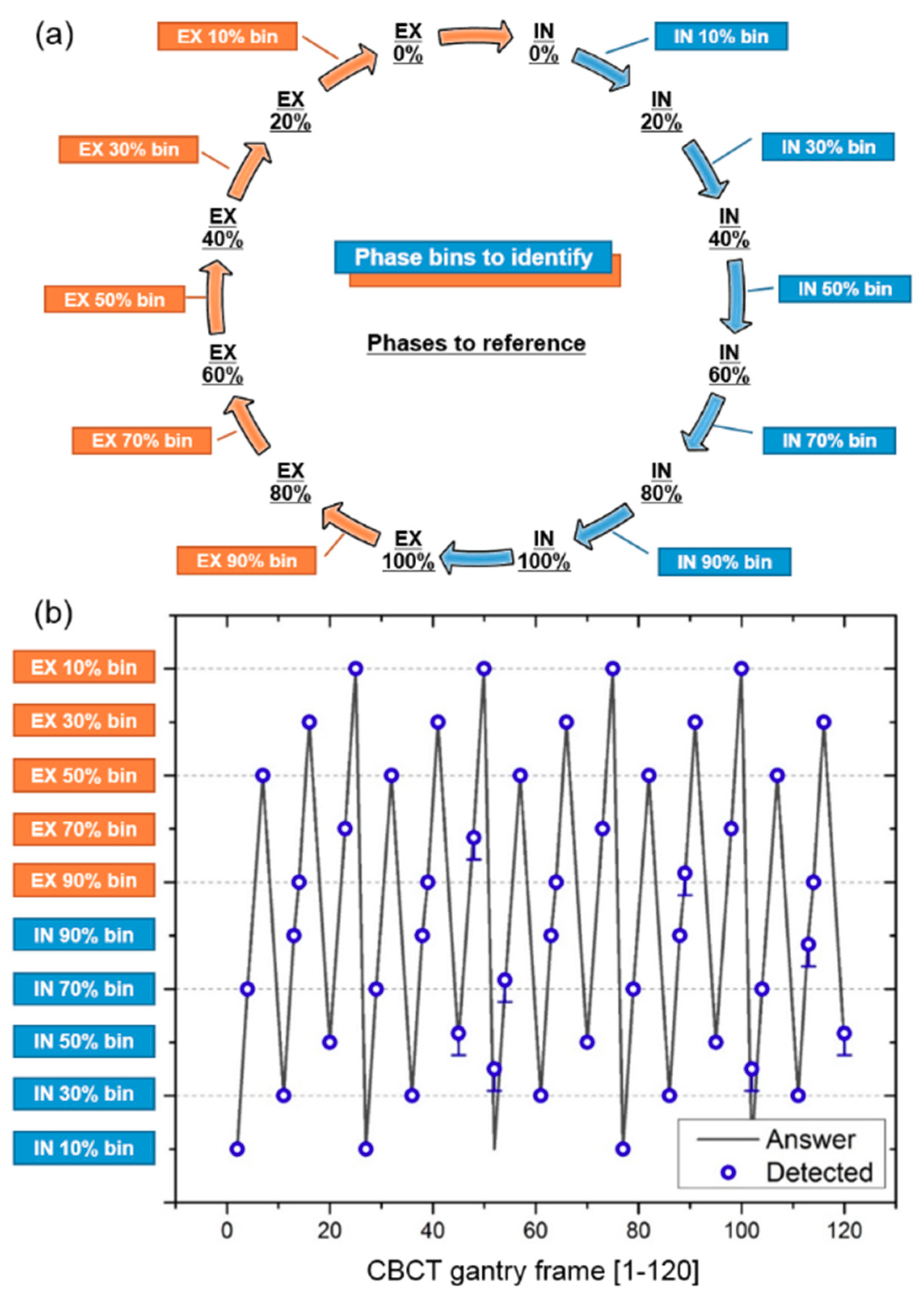
In vivo respiratory-correlated planning 4DCTs of the entire chest of six lung cancer patients were acquired at the department of radiotherapy. The 4DCTs were acquired using a Siemens Sensation Open CT scanner (Siemens AG, Erlangen, Germany) at 120 kVp, 80 mA, and 361 ms. The source-to-detector and source-to-patient distances were 1040 and 570 mm, respectively. The 4D volumetric images were reconstructed for every 10% segment of the respiratory phase with an in-plane resolution of 0.97 × 0.97 mm2 and a slice thickness of 3 mm. The purpose of this study was to track tumors in CBCT projections taken from all directions, which should not be taken in all directions to minimize the radiation dose given to the patient. To simulate the CBCT projections in all directions around the patient, DRRs (i.e., a pseudo projection) were computed for every 10% segment of the respiratory phase with a normal respiration rate in adults at rest (12 breaths/min). Based on ray-casting through the planning 4DCTs of the six patients, 360 CBCT projections were generated for an angular range of the gantry of 360° [35]. Figure 3a shows the selection of the respiratory phase bins to identify (boxed), and the respiratory phases to reference (underlined), from the planning 4DCT projections. The respiratory phase bins to identify were assigned as a function of the gantry frame, as shown in Figure 3b. The correct phase of the projection images for the missing phases (i.e., the phase bins to identify) were detected using the existing respiratory phase data (i.e., the phases to reference).
2.4. Evaluation of the Surrogacy of a Pseudo Projection
A phantom study was conducted to determine the appropriateness of using a pseudo projection as a CBCT projection. A Model 008A Dynamic Thorax Phantom (CIRS, Norfolk, VA, USA) with CIRS motion control software was used to generate the diaphragm motion. A CBCT system equipped with a digital flat-panel detector (41 × 41 cm2, 960 × 961 pixel resolution) was employed to scan the phantom at a frame rate of 7.5 Hz using 80 kVp, 20 mA, and 20 ms.
First, the phantom stopped at a position of 0 cm along the cranial–caudal (C–C) axis, and one CBCT volume of the static phantom was then acquired, which represented one particular breathing phase. Using the volume and system geometric information obtained, 2243 pseudo projections were generated while the gantry was rotating 360° around the phantom. The same number of actual CBCT projections were taken during the 360° rotation around the moving phantom. The diaphragm phantom was set to translate at up to ±2 cm along the cranial–caudal axis, moving along a sinusoidal curve as a function of the gantry frame with a respiratory cycle of 3 s (see Figure A1 in Appendix A). To test how sensitively the motion of the diaphragm can be represented using our image similarity metric, the image similarities between the acquired pseudo projection and actual CBCT projections were computed as a function of the gantry frame. The image similarity measurements were made on a rectangular ROI covering the diaphragm movements.
3. Results
3.1. Respiratory Phase Tracking Accuracy
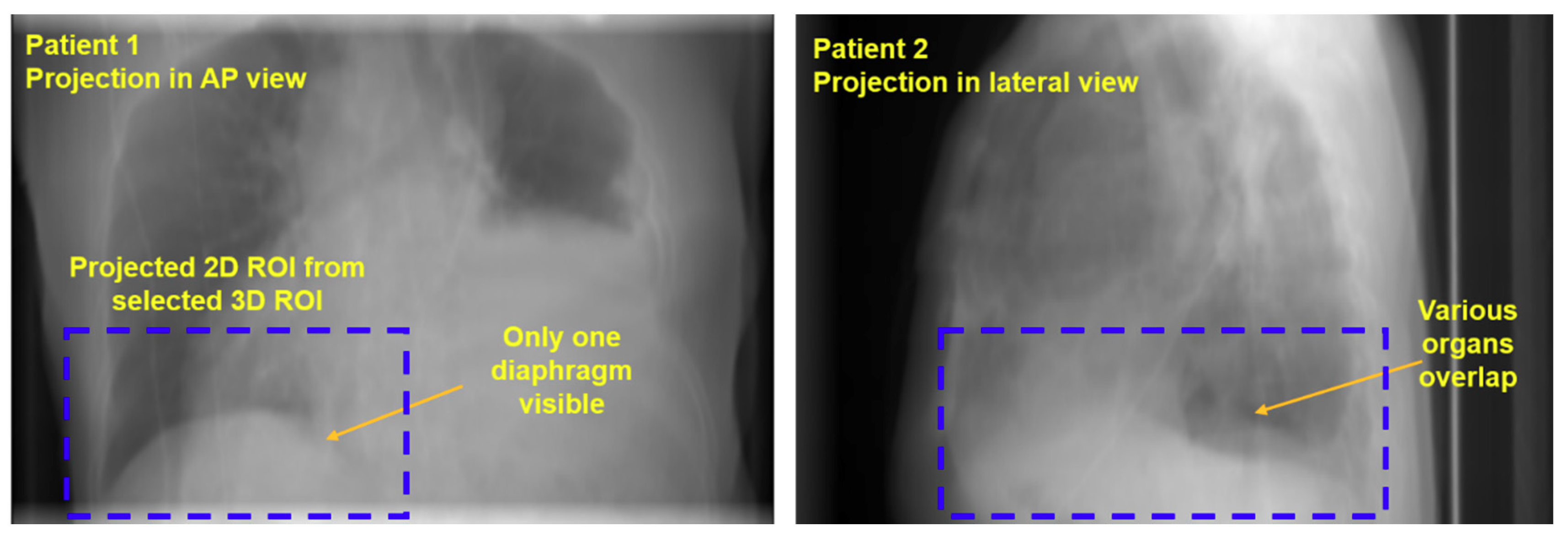
Figure 3b shows the respiration phase assigned to each gantry frame (labeled “Answer”) and the respiratory cycle found by applying the proposed method (labeled “Detected”). The accuracy was calculated for each patient as a percentage of the total number of frames with a correctly identified phase in a total of 120 frames. The method successfully identified the respiratory phase of six patients with an accuracy of 97.2 ± 2.5%. The detailed accuracy of each patient’s respiratory measurement is given in Table 1. The total phase deviation was up to 3 (patient 6) over the entire gantry frame, and the phase deviation was at most 1 per gantry frame with a misidentification of the respiratory phase. Compared to the proposed method, the accuracy of the respiratory phase measurement in the elevation-based method was much lower (40.3 ± 17.0%), as shown in Table 1. The phase deviation was an average of 21.3 (c.f., 1.3 in the proposed method), resulting in a relatively large phase deviation per gantry frame with a misidentification of the respiratory phase. In addition, the accuracy of the inhale/exhale identification was low (48.3%). Figure A2 in Appendix B shows examples of a difficult situation in which the shape of the diaphragm is poorly identified. This method is able to accurately measure the respiration, even in images where only one diaphragm is visible, or when multiple organs including two diaphragms are overlapped.
3.2. Tumor Tracking Accuracy
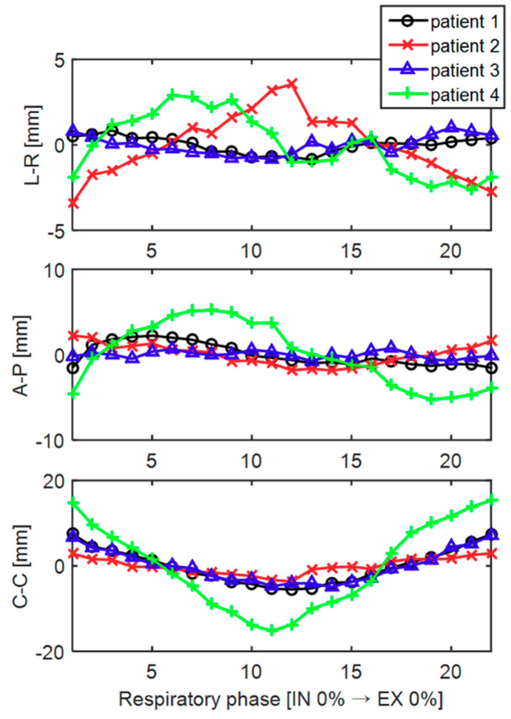
Figure 4 shows the trajectory of the tumor centroid in 3D along the left-right (L-R), anterior-posterior (A-P), and cranial-caudal (C-C) directions over the different respiratory phases for patients 1 through 4. Note that the scales of the Y-axis coordinates of the three directions are not identical. Among the three directions, the tumor generally moved the greatest in the C–C direction. The tumor coordinates tended to increase or decrease around IN 100% (# 11), the boundary between the inspiration and expiration. The specific values for the magnitude of the tumor movement for each patient are shown in Table 2. In the case of patient 4 with a tumor close to the diaphragm, the tumor movement was the largest, and the movement in the CC direction was 30.5 mm. Data on two of the patients (patients 5 and 6) were excluded in the tumor motion analysis because their tumors were located far from the diaphragm, that is, near the upper lung, and the magnitude of the tumor motion was approximately one pixel in size as the motion of the diaphragm had little effect on the tumor motion.
Table 2 shows the 3D tumor tracking accuracy obtained using the proposed method in terms of the Hausdorff surface distance [36] and center-of-mass distance. The surface distance represents the distance between the outer surface of the segmented tumor (i.e., reference) and that of the reconstructed tumor, interpolated through the proposed method. The center-of-mass distance represents the distance between the center of mass of the segmented tumor and that of the reconstructed tumor. As expected, the larger the amplitude of the tumor motion, the greater the likelihood that tumor tracking errors in both metrics increase. However, for all four patients, the tumor was tracked with an accuracy of less than 1 mm, which is close to the in-plane resolution (0.97 × 0.97 mm2) of the reconstructed 4DCT volumes.
3.3. Phantom Evaluation
Figure A1a shows a representative CBCT projection and pseudo projection (i.e., DRR). The image similarity (SSIM) was measured for each gantry frame between the pseudo projections of the static phantom and the CBCT projections of the moving phantom, as shown in Figure A1b. The SSIM value can have a value of between zero and 1, which means that the two images to compare are identical. The SSIM value was very close to 1 (0.9589 ± 0.0233) when the CBCT projections reached a position of 0 cm (circled) along the cranial–caudal axis, that is, when they coincided with the respiratory phase on the pseudo projections. In addition, when the diaphragm moved even slightly (dotted line), the SSIM value changed sensitively (solid line).
4. Discussion
Radiation therapy plays an important role in the treatment of patients with lung tumors, and is usually used alone or in combination with chemotherapy or surgery. The purpose of radiation therapy is to deliver radiation to the tumor in the patient’s body. As technology develops further, it will be possible to emit radiation more precisely into the tumor [5,6,37,38], but such accuracy remains very difficult to achieve.
The method presented in this study has demonstrated the feasibility of tracking the respiratory phase and 3D tumor position in real time during treatment using a kV image mounted on the treatment system. The proposed method works well even under poor conditions in which the shape of the diaphragm is not clear, and regardless of the irradiation angle, that is, the gantry angle, the method shows a good level of performance, i.e., a respiration phase tracking accuracy of (n = 6) = 97.2 ± 2.5%, and tumor tracking error in 3D of (n = 4) = 0.9 ± 0.4 mm. To the best of our knowledge, previous imaging-based tumor tracking methods have been applied only at certain angles (e.g., the anterior–posterior direction) where the tumor is relatively well visible [5,6,24,25,26]; however, the proposed method tracked the tumor’s 3D location successfully at any angle of the gantry with sub-millimeter accuracy using a gantry-mounted on-board X-ray imaging system. Other tracking systems such as implanted fiducials [17,18] or electromagnetic beacons (i.e., Calypso system) [39,40] can track the tumor’s 3D position at any gantry angle because they are not limited by the gantry’s position at any given point in the treatment. However, the patient may become uncomfortable with such an invasive procedure, which also poses a risk of complications clinically, such as the occurrence of a pneumothorax [41,42,43]. A variety of potential advantages are expected to be achieved when high-precision radiation therapy is eventually enabled using this method. In addition to improving the success rate of radiation therapy, the quality of life of the patient can be improved by reducing the risk of complications of radiation therapy. Radiation therapies, which are difficult to perform owing to the presence of important structures near the tumor, including the spinal cord, may become applicable if accurate targeting is made possible.
The performance of an elevation-based method (40.3 ± 17.0%) is much lower than that of the method proposed herein (97.2 ± 2.5%). Given the fact that the inhale/exhale identification accuracy (48.3%) is close to the accuracy achieved through a diaphragm elevation-based method (40.3%), most identification errors are due to a failure of inhale/exhale identification. The amplitude of the breathing can be analyzed well based on high- and low-diaphragmatic information, but this method alone fails to identify whether the current breathing is in an inspiratory or expiratory state. As shown in Figure 4, the 3D trajectory of the tumor showed hysteresis, as evidenced through previous studies [44,45], and thus inhale/exhale identification must be conducted to track the tumor in real time while the patient is breathing.
The proposed method identifies the respiratory phase through two steps: (1) a structural-similarity based ranking and (2) comparing the hemidiaphragm area. Some may feel that step (1) can be skipped. However, step (1) is necessary to determine whether the current breath is in an inspiratory or expiratory state, thereby determining the respiratory phase candidates to be applied during the second step. Similar to the problems of the elevation-based method mentioned above, a low performance is shown when step (1) is not applied. The elevation-based method has roughly a 50% accuracy when distinguishing between inhale and exhale phase as it only has one image at its disposal, and mid-inhale and mid-exhale phases can look very similar. Moreover, the proposed method performs robustly for projections of every 10% segment of the respiratory cycle. Given that the SSIM is sensitive to slight movements of the diaphragm phantom, as shown in Figure A1, treatment projections with respiratory phases of finer than 10% should be identifiable.
Several major limitations of this study should be addressed. First, we did not consider changes in the tumor position that occur from the heartbeat separately from those occurring from respiration. However, when the tumor was located in the upper part of the lung, the movement of the tumor was slight (patients 5 and 6), whereas a tumor close to the diaphragm showed a large movement (patients 1 through 4). Moreover, the movement of the tumor was mainly seen in the cranial–caudal direction (Figure 4, [5,6,44,46]), which is the same as the motion pattern of the diaphragm. Based on these observations, most movements of the tumor can be explained by the motion of the diaphragm alone. Second, owing to the problem of the radiation dose administered to the patient, CBCT projections cannot be obtained by moving around the patient in all directions, and thus pseudo projections were created for every 10% segment of the respiratory phase instead. However, in the phantom study, the SSIM between the actual CBCT projections and their corresponding pseudo projections was close to 1 (0.9589 ± 0.0233). Thus, it can be said that our pseudo projection is a good surrogate for an actual projection. In addition, because a pseudo image has a lower contrast than an actual projection, the diaphragm extraction on a pseudo projection is relatively difficult to detect. Because the proposed method was evaluated under worse conditions than those found in an actual situation, the use of an actual image is not expected to lead to a deterioration in the performance. Lastly, because kV imaging is needed in addition to treatment beam, the patient is exposed to an extra radiation dose. Patients with non-small-cell lung cancer are treated with a high dose of within 63 to 103 Gy during radiation therapy [47], compared to which, the amount of radiation delivered by the additional kV images is quite small. Thus, if a small increase in dose can reduce the therapeutic beam exposure to healthy tissue around the tumor, it will be of benefit to the patient.
5. Conclusions
In this paper, we demonstrated the feasibility of a technique used to track the respiratory phase and 3D tumor position in real time during treatment using kV fluoroscopy acquired from arbitrary angles around the patient. The proposed method accurately works even on an image with poor diaphragmatic vision, and the method shows a good level of performance regardless of the irradiation angle. Various potential benefits are expected to be achieved when high-precision radiation therapy is eventually enabled using the proposed method.
Author Contributions
J.-H.C. conceived of the presented idea. J.-H.C. and S.L. carried out the experiment. J.-H.C. analyzed the results and wrote the manuscript with support from S.L.
Funding
This work was supported by the National Research Foundation of Korea (NRF) grant funded by the Korean government (MSIP: Ministry of Science, ICT and Future Planning) (No. NRF-2017R1C1B5018287 and NRF-2017M2A2A6A02070522), and by the Ewha Womans University Research Grant of 2017.
Acknowledgments
The authors thank Young Nam Kang from Department of Radiation Oncology, The Catholic University of Korea for his help in setting up an experiment.
Conflicts of Interest
The authors declare no conflict of interest.
Appendix A
Figure A1.
Evaluation of similarity between our DRR images and their corresponding actual X-ray images using dynamic diaphragm phantom data with motion control. (a) Representative x-ray projection and pseudo projection (i.e., DRR) images. (b) SSIM between X-ray projections of a moving phantom and DRRs of a static phantom for each frame.

Appendix B
Figure A2.
Representative projections of the patients in a bad condition in which the shape of the diaphragm is not easily identifiable.
Figure A2.
Representative projections of the patients in a bad condition in which the shape of the diaphragm is not easily identifiable.

References
- Ling, C.C.; Yorke, E.; Amols, H.; Mechalakos, J.; Erdi, Y.; Leibel, S.; Rosenzweig, K.; Jackson, A. High-tech will improve radiotherapy of NSCLC: A hypothesis waiting to be validated. Int. J. Radiat. Oncol. Biol. Phys. 2004, 60, 3–7. [Google Scholar] [CrossRef] [PubMed]
- Engelsman, M.; Damen, E.M.; De Jaeger, K.; van Ingen, K.M.; Mijnheer, B.J. The effect of breathing and set-up errors on the cumulative dose to a lung tumor. Radiother. Oncol. 2001, 60, 95–105. [Google Scholar] [CrossRef]
- Pan, T.; Lee, T.Y.; Rietzel, E.; Chen, G.T. 4D-CT imaging of a volume influenced by respiratory motion on multi-slice CT. Med. Phys. 2004, 31, 333–340. [Google Scholar] [CrossRef] [PubMed]
- Li, R.; Lewis, J.H.; Cervino, L.I.; Jiang, S.B. 4D CT sorting based on patient internal anatomy. Phys. Med. Biol. 2009, 54, 4821–4833. [Google Scholar] [CrossRef] [PubMed]
- Furtado, H.; Steiner, E.; Stock, M.; Georg, D.; Birkfellner, W. Real-time 2D/3D registration using kV-MV image pairs for tumor motion tracking in image guided radiotherapy. Acta. Oncol. 2013, 52, 1464–1471. [Google Scholar] [CrossRef] [PubMed] [Green Version]
- Gendrin, C.; Furtado, H.; Weber, C.; Bloch, C.; Figl, M.; Pawiro, S.A.; Bergmann, H.; Stock, M.; Fichtinger, G.; Georg, D.; et al. Monitoring tumor motion by real time 2D/3D registration during radiotherapy. Radiother. Oncol. 2012, 102, 274–280. [Google Scholar] [CrossRef] [PubMed] [Green Version]
- Negoro, Y.; Nagata, Y.; Aoki, T.; Mizowaki, T.; Araki, N.; Takayama, K.; Kokubo, M.; Yano, S.; Koga, S.; Sasai, K.; et al. The effectiveness of an immobilization device in conformal radiotherapy for lung tumor: Reduction of respiratory tumor movement and evaluation of the daily setup accuracy. Int. J. Radiat. Oncol. Biol. Phys. 2001, 50, 889–898. [Google Scholar] [CrossRef]
- Simon, L.; Giraud, P.; Servois, V.; Rosenwald, J.C. Comparative study and clinical implementation of two breathing-adapted radiotherapy techniques: Dosimetric benefits for lung cancer treatment. Cancer Radiother. 2006, 10, 370–376. [Google Scholar] [CrossRef] [PubMed]
- Rietzel, E.; Pan, T.; Chen, G.T. Four-dimensional computed tomography: Image formation and clinical protocol. Med. Phys. 2005, 32, 874–889. [Google Scholar] [CrossRef] [PubMed]
- Li, X.A.; Stepaniak, C.; Gore, E. Technical and dosimetric aspects of respiratory gating using a pressure-sensor motion monitoring system. Med. Phys. 2006, 33, 145–154. [Google Scholar] [CrossRef] [PubMed]
- Onishi, H.; Kawakami, H.; Marino, K.; Komiyama, T.; Kuriyama, K.; Araya, M.; Saito, R.; Aoki, S.; Araki, T. A simple respiratory indicator for irradiation during voluntary breath holding: A one-touch device without electronic materials. Radiology 2010, 255, 917–923. [Google Scholar] [CrossRef] [PubMed]
- Hughes, S.; McClelland, J.; Tarte, S.; Lawrence, D.; Ahmad, S.; Hawkes, D.; Landau, D. Assessment of two novel ventilatory surrogates for use in the delivery of gated/tracked radiotherapy for non-small cell lung cancer. Radiother. Oncol. 2009, 91, 336–341. [Google Scholar] [CrossRef] [PubMed]
- Cho, B.; Suh, Y.; Dieterich, S.; Keall, P.J. A monoscopic method for real-time tumour tracking using combined occasional x-ray imaging and continuous respiratory monitoring. Phys. Med. Biol. 2008, 53, 2837–2855. [Google Scholar] [CrossRef] [PubMed]
- Rong, Y.; Walston, S.; Welliver, M.X.; Chakravarti, A.; Quick, A.M. Improving intra-fractional target position accuracy using a 3D surface surrogate for left breast irradiation using the respiratory-gated deep-inspiration breath-hold technique. PLoS ONE 2014, 9, e97933. [Google Scholar] [CrossRef] [PubMed]
- Zhao, B.; Yang, Y.; Li, T.; Li, X.; Heron, D.E.; Huq, M.S. Statistical analysis of target motion in gated lung stereotactic body radiation therapy. Phys. Med. Biol. 2011, 56, 1385–1395. [Google Scholar] [CrossRef] [PubMed]
- Anderson, M.M. Investigating the robustness of the Anzai respiratory gating system. Master’s Thesis, University of Canterbury, Christchuch, Canterbury, New Zealand, April 2013. [Google Scholar]
- Shirato, H.; Harada, T.; Harabayashi, T.; Hida, K.; Endo, H.; Kitamura, K.; Onimaru, R.; Yamazaki, K.; Kurauchi, N.; Shimizu, T.; et al. Feasibility of insertion/implantation of 2.0-mm-diameter gold internal fiducial markers for precise setup and real-time tumor tracking in radiotherapy. Int. J. Radiat. Oncol. Biol. Phys. 2003, 56, 240–247. [Google Scholar] [CrossRef]
- Shirato, H.; Oita, M.; Fujita, K.; Watanabe, Y.; Miyasaka, K. Feasibility of synchronization of real-time tumor-tracking radiotherapy and intensity-modulated radiotherapy from viewpoint of excessive dose from fluoroscopy. Int. J. Radiat. Oncol. Biol. Phys. 2004, 60, 335–341. [Google Scholar] [CrossRef] [PubMed]
- Shah, A.P.; Kupelian, P.A.; Willoughby, T.R.; Langen, K.M.; Meeks, S.L. An evaluation of intrafraction motion of the prostate in the prone and supine positions using electromagnetic tracking. Radiother. Oncol. 2011, 99, 37–43. [Google Scholar] [CrossRef] [PubMed]
- Langen, K.M.; Willoughby, T.R.; Meeks, S.L.; Santhanam, A.; Cunningham, A.; Levine, L.; Kupelian, P.A. Observations on real-time prostate gland motion using electromagnetic tracking. Int. J. Radiat. Oncol. Biol. Phys. 2008, 71, 1084–1090. [Google Scholar] [CrossRef] [PubMed]
- Shirato, H.; Shimizu, S.; Kitamura, K.; Nishioka, T.; Kagei, K.; Hashimoto, S.; Aoyama, H.; Kunieda, T.; Shinohara, N.; Dosaka-Akita, H.; et al. Four-dimensional treatment planning and fluoroscopic real-time tumor tracking radiotherapy for moving tumor. Int. J. Radiat. Oncol. Biol. Phys. 2000, 48, 435–442. [Google Scholar] [CrossRef]
- Yang, Z.Y.; Chang, Y.; Liu, H.Y.; Liu, G.; Li, Q. Target margin design for real-time lung tumor tracking stereotactic body radiation therapy using CyberKnife Xsight Lung Tracking System. Sci. Rep. 2017, 7, 10826. [Google Scholar] [CrossRef] [PubMed] [Green Version]
- Ipsen, S.; Bruder, R.; O’Brien, R.; Keall, P.J.; Schweikard, A.; Poulsen, P.R. Online 4D ultrasound guidance for real-time motion compensation by MLC tracking. Med. Phys. 2016, 43, 5695. [Google Scholar] [CrossRef] [PubMed]
- Cui, Y.; Dy, J.G.; Sharp, G.C.; Alexander, B.; Jiang, S.B. Multiple template-based fluoroscopic tracking of lung tumor mass without implanted fiducial markers. Phys. Med. Biol. 2007, 52, 6229–6242. [Google Scholar] [CrossRef] [PubMed]
- Lin, T.; Cervino, L.I.; Tang, X.; Vasconcelos, N.; Jiang, S.B. Fluoroscopic tumor tracking for image-guided lung cancer radiotherapy. Phys. Med. Biol. 2009, 54, 981–992. [Google Scholar] [CrossRef] [PubMed]
- Xu, Q.; Hamilton, R.J.; Schowengerdt, R.A.; Alexander, B.; Jiang, S.B. Lung tumor tracking in fluoroscopic video based on optical flow. Med. Phys. 2008, 35, 5351–5359. [Google Scholar] [CrossRef] [PubMed] [Green Version]
- Xu, Q.; Hamilton, R.J.; Schowengerdt, R.A.; Jiang, S.B. A deformable lung tumor tracking method in fluoroscopic video using active shape models: A feasibility study. Phys. Med. Biol. 2007, 52, 5277–5293. [Google Scholar] [CrossRef] [PubMed]
- Lewis, J.H.; Li, R.; Watkins, W.T.; Lawson, J.D.; Segars, W.P.; Cervino, L.I.; Song, W.Y.; Jiang, S.B. Markerless lung tumor tracking and trajectory reconstruction using rotational cone-beam projections: A feasibility study. Phys. Med. Biol. 2010, 55, 2505–2522. [Google Scholar] [CrossRef] [PubMed]
- Wang, Z.; Bovik, A.C.; Sheikh, H.R.; Simoncelli, E.P. Image quality assessment: From error visibility to structural similarity. IEEE Trans. Image Process. 2004, 13, 600–612. [Google Scholar] [CrossRef] [PubMed]
- Otsu, N. A Threshold Selection Method from Gray-Level Histograms. IEEE Trans. Syst. Man Cybern. 1979, 9, 62–66. [Google Scholar] [CrossRef]
- Chen, Q.S.; Weinhous, M.S.; Deibel, F.C.; Ciezki, J.P.; Macklis, R.M. Fluoroscopic study of tumor motion due to breathing: Facilitating precise radiation therapy for lung cancer patients. Med. Phys. 2001, 28, 1850–1856. [Google Scholar] [CrossRef] [PubMed]
- Xu, Q.; Hamilton, R.J. A novel respiratory detection method based on automated analysis of ultrasound diaphragm video. Med. Phys. 2006, 33, 916–921. [Google Scholar] [CrossRef] [PubMed]
- Besl, P.J.; McKay, N.D. A method for registration of 3-D shapes. IEEE Trans. Pattern Anal. 1992, 14, 239–256. [Google Scholar] [CrossRef]
- Friedman, J.H.; Bentley, J.L.; Finkel, R.A. An algorithm for finding best matches in logarithmic expected time. ACM Trans. Math. Softw. 1977, 3, 209–226. [Google Scholar] [CrossRef]
- Maier, A.; Hofmann, H.G.; Schwemmer, C.; Hornegger, J.; Keil, A.; Fahrig, R. Fast simulation of x-ray projections of spline-based surfaces using an append buffer. Phys. Med. Biol. 2012, 57, 6193–6210. [Google Scholar] [CrossRef] [PubMed] [Green Version]
- Rote, G. Computing the minimum Hausdorff distance between two point sets on a line under translation. Inf. Process. Lett. 1991, 38, 123–127. [Google Scholar] [CrossRef] [Green Version]
- Bral, S.; Van Parijs, H.; Soete, G.; Linthout, N.; Van Moorter, L.; Verellen, D.; Storme, G. A feasibility study of image-guided hypofractionated conformal arc therapy for inoperable patients with localized non-small cell lung cancer. Radiother. Oncol. 2007, 84, 252–256. [Google Scholar] [CrossRef] [PubMed]
- Stock, M.; Kontrisova, K.; Dieckmann, K.; Bogner, J.; Poetter, R.; Georg, D. Development and application of a real-time monitoring and feedback system for deep inspiration breath hold based on external marker tracking. Med. Phys. 2006, 33, 2868–2877. [Google Scholar] [CrossRef] [PubMed]
- Parikh, P.; Hubenschmidt, J.; Dimmer, S.; Vertatschitsch, E.; Eidens, R.; Wright, J.N.; Low, D.A. 4D verification of real-time accuracy of the Calypso system with lung cancer patient trajectory data. Int. J. Radiat. Oncol. 2005, 63, S26–S27. [Google Scholar] [CrossRef]
- Burch, D.; Willoughby, T.; Meeks, S.; Kupelian, P.; Litzenberg, D.; Sandler, H.; Levine, L.; Vertatschitsch, D.; Vertatschitsch, E. Real time prostate translation, rotation, deformation evaluated with Calypso beacon (TM) transponders. Int. J. Radiat. Oncol. 2005, 63, S195. [Google Scholar] [CrossRef]
- Geraghty, P.R.; Kee, S.T.; McFarlane, G.; Razavi, M.K.; Sze, D.Y.; Dake, M.D. CT-guided transthoracic needle aspiration biopsy of pulmonary nodules: Needle size and pneumothorax rate. Radiology 2003, 229, 475–481. [Google Scholar] [CrossRef] [PubMed]
- Whyte, R.I.; Crownover, R.; Murphy, M.J.; Martin, D.P.; Rice, T.W.; DeCamp, M.M., Jr.; Rodebaugh, R.; Weinhous, M.S.; Le, Q.T. Stereotactic radiosurgery for lung tumors: Preliminary report of a phase I trial. Ann. Thorac. Surg. 2003, 75, 1097–1101. [Google Scholar] [CrossRef]
- Arslan, S.; Yilmaz, A.; Bayramgurler, B.; Uzman, O.; Nver, E.; Akkaya, E. CT- guided transthoracic fine needle aspiration of pulmonary lesions: Accuracy and complications in 294 patients. Med. Sci. Monit. 2002, 8, CR493–CR497. [Google Scholar] [PubMed]
- Seppenwoolde, Y.; Shirato, H.; Kitamura, K.; Shimizu, S.; van Herk, M.; Lebesque, J.V.; Miyasaka, K. Precise and real-time measurement of 3D tumor motion in lung due to breathing and heartbeat, measured during radiotherapy. Int. J. Radiat. Oncol. Biol. Phys. 2002, 53, 822–834. [Google Scholar] [CrossRef]
- Ruan, D.; Fessler, J.A.; Balter, J.M.; Berbeco, R.I.; Nishioka, S.; Shirato, H. Inference of hysteretic respiratory tumor motion from external surrogates: A state augmentation approach. Phys. Med. Biol. 2008, 53, 2923–2936. [Google Scholar] [CrossRef] [PubMed]
- Suh, Y.; Dieterich, S.; Cho, B.; Keall, P.J. An analysis of thoracic and abdominal tumour motion for stereotactic body radiotherapy patients. Phys. Med. Biol. 2008, 53, 3623–3640. [Google Scholar] [CrossRef] [PubMed]
- Kong, F.M.; Ten Haken, R.K.; Schipper, M.J.; Sullivan, M.A.; Chen, M.; Lopez, C.; Kalemkerian, G.P.; Hayman, J.A. High-dose radiation improved local tumor control and overall survival in patients with inoperable/unresectable non-small-cell lung cancer: Long-term results of a radiation dose escalation study. Int. J. Radiat. Oncol. Biol. Phys. 2005, 63, 324–333. [Google Scholar] [CrossRef] [PubMed]
Figure 1.
Pipelines for respiratory phase identification. As shown in (a), after preprocessing the image, the current respiratory phase was determined using an image similarity test and the area of the diaphragm. (b) Representative structural similarity (SSIM) rank profiles as a function of the respiratory phase.

Figure 2.
Procedure used to compare the diaphragm area on a 2D digitally rendered radiographs (DRR) or fluoroscopy. (a) Comparison procedures for the hemidiaphragm area of the projection with 1st, 2nd, and 3rd rankings. (b) Example of a binarized, dynamic pixel map used during the procedure.
Figure 2.
Procedure used to compare the diaphragm area on a 2D digitally rendered radiographs (DRR) or fluoroscopy. (a) Comparison procedures for the hemidiaphragm area of the projection with 1st, 2nd, and 3rd rankings. (b) Example of a binarized, dynamic pixel map used during the procedure.

Figure 3.
(a) Selection of respiratory phase bins to identify (boxed), and respiratory phases to reference (underlined), from the planning 4DCT images for each 10% of the respiratory phase. (b) The respiratory phase bins to identify were assigned as a function of the gantry frame. The correct phase of the projection images of the missing phases (phase bins to identify) were detected using the existing respiratory phase data (phases to reference). The correct and detected phases achieved using the proposed method are labeled “Answer” and “Detected,” respectively.

Figure 4.
The trajectory of the tumor centroid in 3D along left–right (L–R), anterior–posterior (A–P), and cranial–caudal (C–C) directions over the different respiratory phases for patients 1 through 4.
Figure 4.
The trajectory of the tumor centroid in 3D along left–right (L–R), anterior–posterior (A–P), and cranial–caudal (C–C) directions over the different respiratory phases for patients 1 through 4.


Table 1.
The respiratory phase identification performance of the proposed method compared with the previous diaphragm elevation-based method in terms of the inhale/exhale identification, phase deviation, and accuracy.
Table 1.
The respiratory phase identification performance of the proposed method compared with the previous diaphragm elevation-based method in terms of the inhale/exhale identification, phase deviation, and accuracy.
| Diaphragm-Elevation Based Method | Proposed Method | |||||
|---|---|---|---|---|---|---|
| Inhale/Exhale Identification * (%) | Phase Deviation † (#) | Accuracy (%) | Inhale/Exhale Identification * (%) | Phase Deviation † (#) | Accuracy (%) | |
| Patient 1 | 68.8 | 4 | 60.4 | 100 | 1 | 97.9 |
| Patient 2 | 41.7 | 24 | 52.1 | 100 | 2 | 95.8 |
| Patient 3 | 39.6 | 18 | 47.9 | 100 | 0 | 100 |
| Patient 4 | 50 | 9 | 41.7 | 100 | 0 | 100 |
| Patient 5 | 41.7 | 24 | 20.8 | 100 | 2 | 95.8 |
| Patient 6 | 47.9 | 49 | 18.8 | 95.8 | 3 | 93.8 |
| Total | 48.3 | 21.3 | 40.3 ± 17.0 | 99.3 | 1.3 | 97.2 ± 2.5 |
* Inhale/exhale identification: the accuracy in identifying whether the phase belongs to an inhalation or exhalation; † Phase deviation: total deviation of the identified respiratory rate from the correct respiratory rate.
Table 2.
Tumor motion during the entire respiratory cycle along the L–R, A–P, and C–C directions for patients 1 through 4. The tumor motion is reported in terms of the maximum amplitude (max-min) and standard deviation (SD) of the centroid of mass of the tumors. The patients (patients 5 and 6) with little tumor motion (amplitude of < 1 mm) are not reported.
| Amplitude (mm) | SD (mm) | Tumor Tracking Error in 3D (mm) | ||||||
|---|---|---|---|---|---|---|---|---|
| L–R * | A–P * | C–C * | L–R | A–P | C–C | Surface Distance | Center of Mass Distance | |
| Patient 1 | 1.7 | 3.8 | 13.0 | 0.5 | 1.3 | 4.1 | 0.9 (± 0.4) | 0.6 (± 0.5) |
| Patient 2 | 7.0 | 4.1 | 6.6 | 1.8 | 1.2 | 1.9 | 0.7 (± 0.3) | 0.7 (± 0.4) |
| Patient 3 | 1.9 | 1.5 | 12.0 | 0.5 | 0.4 | 3.8 | 0.8 (± 0.4) | 0.8 (± 0.2) |
| Patient 4 | 5.5 | 10.4 | 30.5 | 1.8 | 3.8 | 10.2 | 1.0 (± 0.5) | 1.0 (± 0.4) |
* L–R = left to right, A–P = anterior to posterior, C–C = cranial to caudal.
© 2018 by the authors. Licensee MDPI, Basel, Switzerland. This article is an open access article distributed under the terms and conditions of the Creative Commons Attribution (CC BY) license (http://creativecommons.org/licenses/by/4.0/).
Share and Cite
MDPI and ACS Style
Choi, J.-H.; Lee, S. Real-Time Tumor Motion Tracking in 3D Using Planning 4D CT Images during Image-Guided Radiation Therapy. Algorithms 2018, 11, 155. https://doi.org/10.3390/a11100155
AMA Style
Choi J-H, Lee S. Real-Time Tumor Motion Tracking in 3D Using Planning 4D CT Images during Image-Guided Radiation Therapy. Algorithms. 2018; 11(10):155. https://doi.org/10.3390/a11100155
Chicago/Turabian StyleChoi, Jang-Hwan, and Sooyeul Lee. 2018. "Real-Time Tumor Motion Tracking in 3D Using Planning 4D CT Images during Image-Guided Radiation Therapy" Algorithms 11, no. 10: 155. https://doi.org/10.3390/a11100155
Note that from the first issue of 2016, this journal uses article numbers instead of page numbers. See further details here.