
Investigation on the Effect of Drill Geometry and Pilot Holes on Thrust Force and Burr Height When Drilling an Aluminium/PE Sandwich Material


Abstract
:1. Introduction
2. Materials and Methods
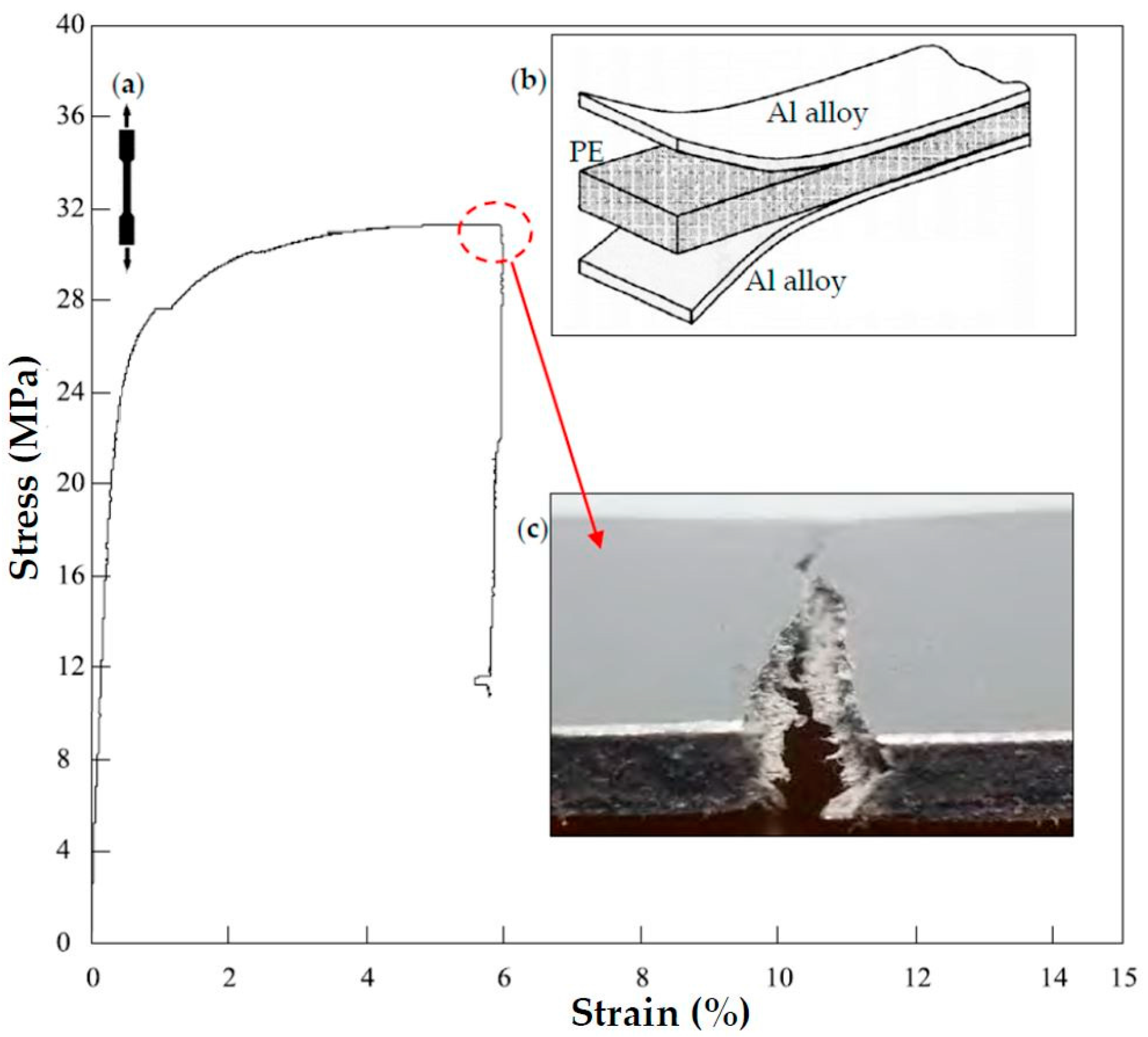
2.1. Material
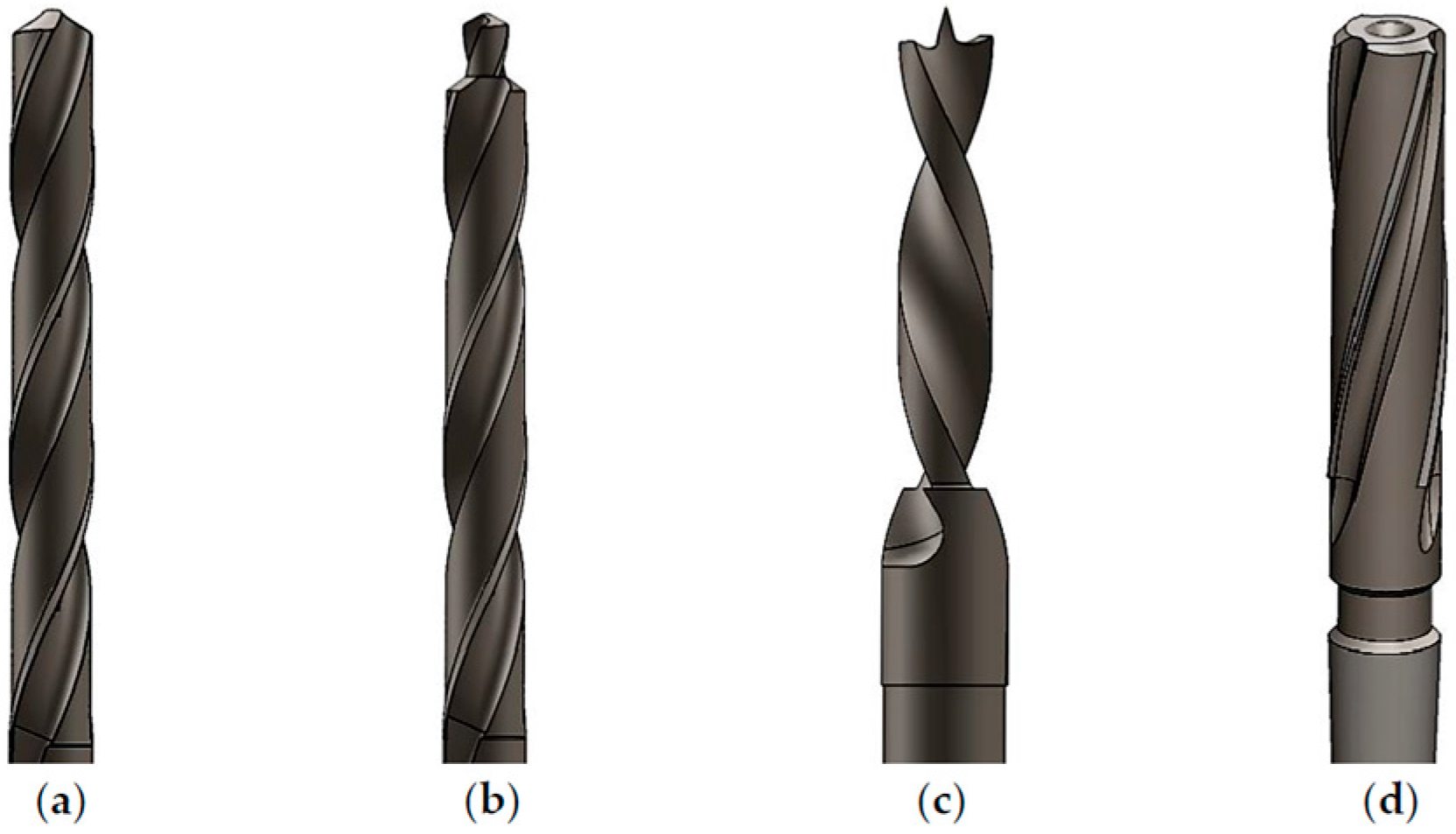
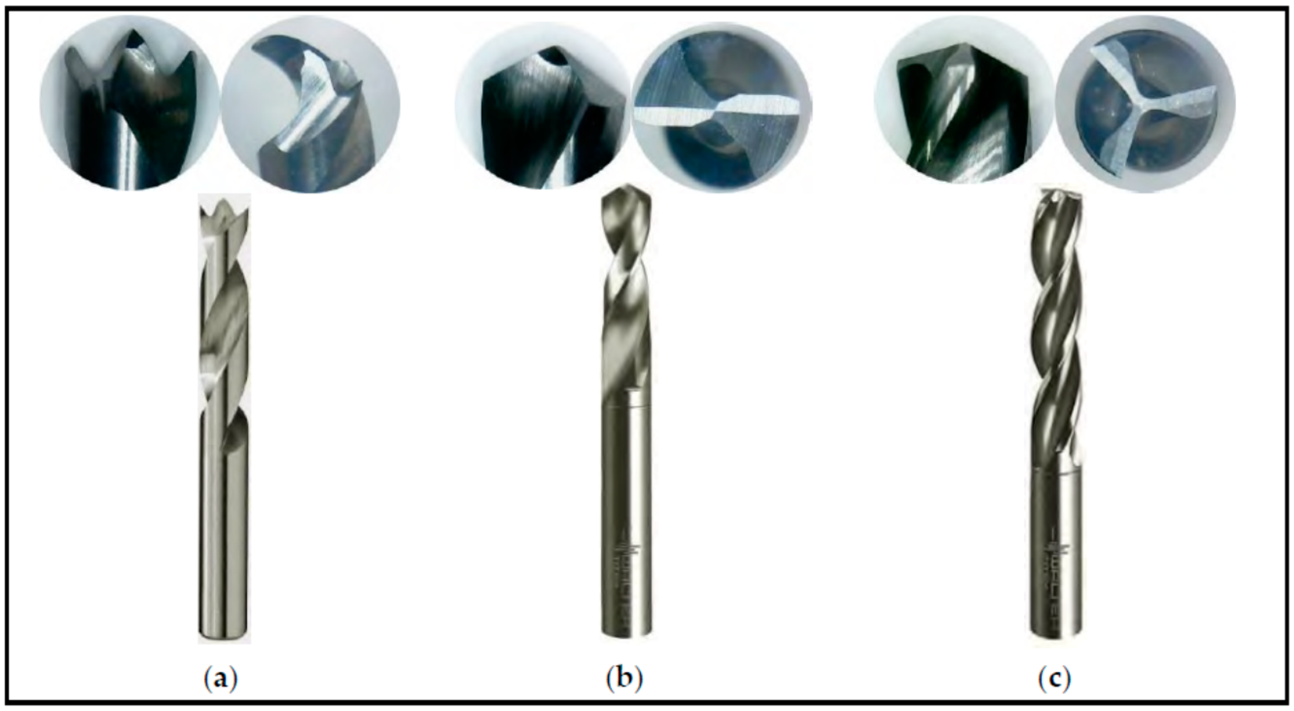
2.2. Cutting Tools
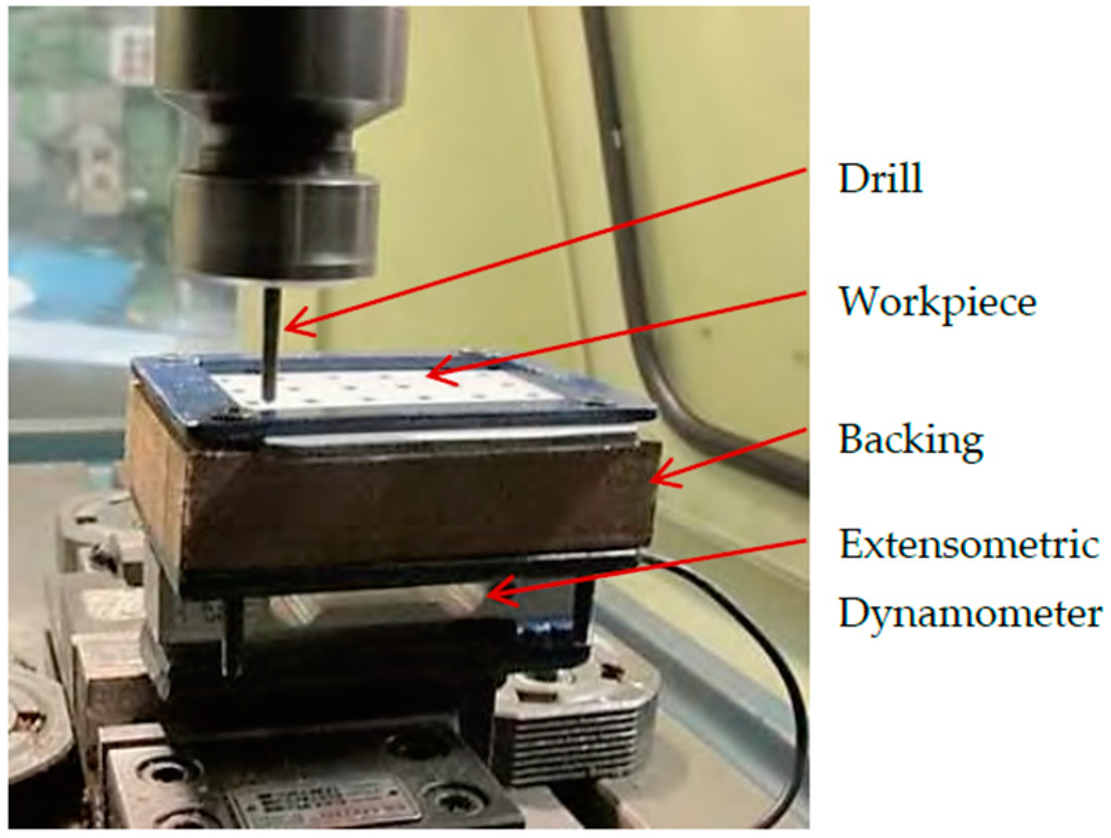
2.3. Experimental Set-Up
3. Results and Discussion
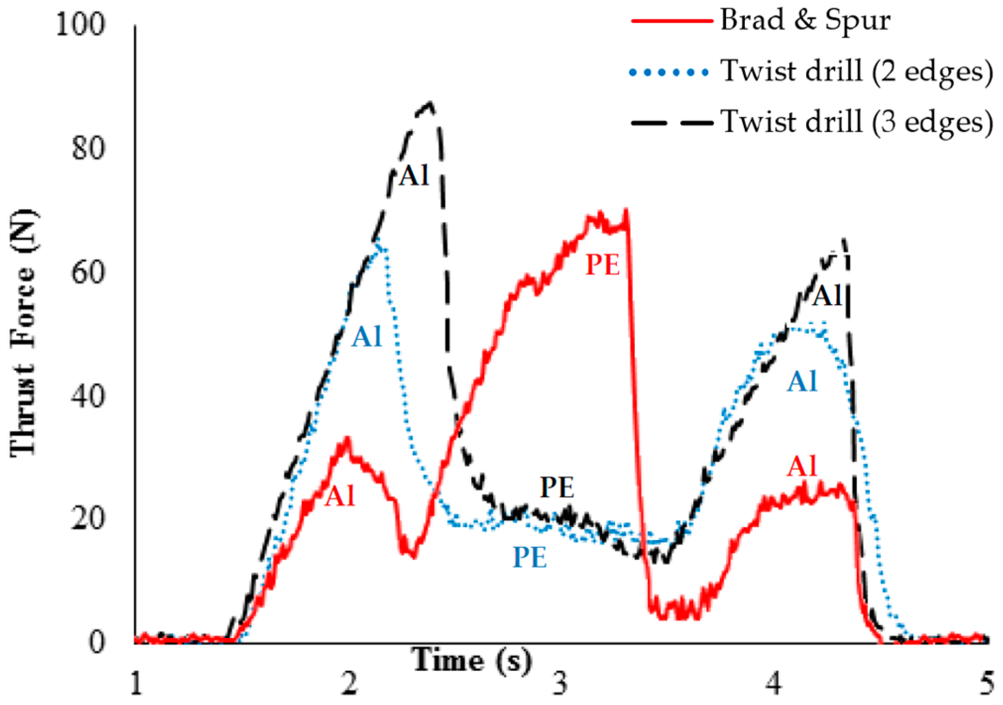
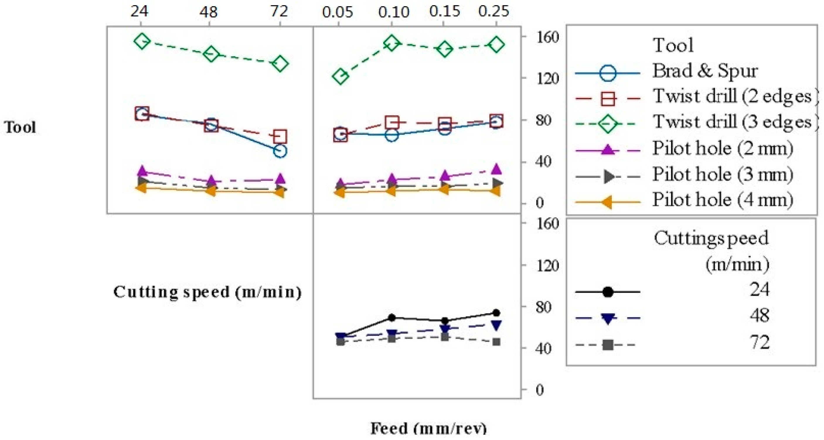
3.1. Thrust Force
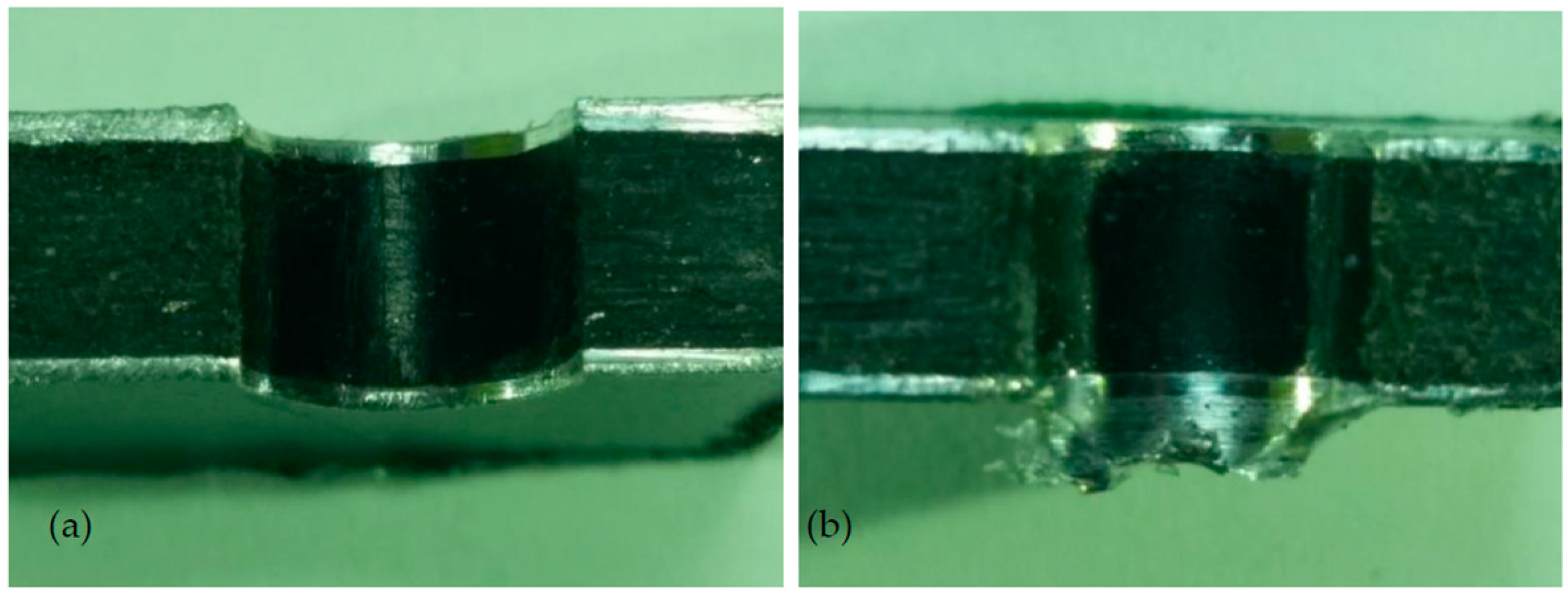
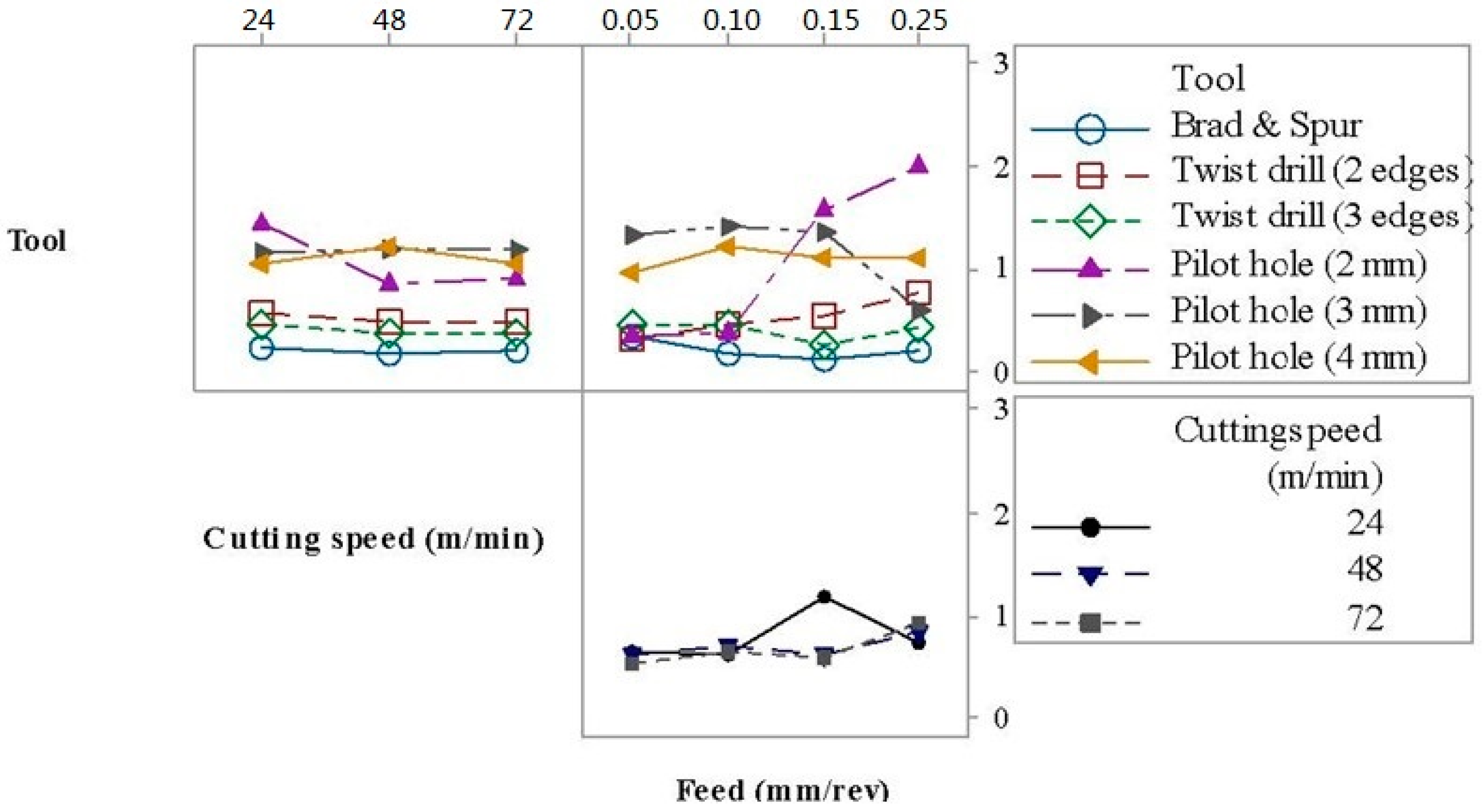
3.2. Burr Height
4. Conclusions
- All investigated factors and second-order interactions significantly affected thrust force. The thrust force decreased with the elevation of the cutting speed (due to work material softening) and increased with the feed rate (higher shear area). The Brad and Spur drill geometry required a lower thrust force compared with the twist drills with two and three cutting edges and the presence of a pilot hole contributed to the reduction of the thrust force.
- Drill geometry and feed rate, as well as all the second- and third-order interactions, were the factors that significantly affected the burr height. The Brad and Spur geometry was responsible for shorter burrs and the presence of a pilot hole facilitated plastic deformation, thus leading to the elevation of the burr height.
Acknowledgments
Author Contributions
Conflicts of Interest
References
- Callister, W.D.; Rethwisch, D.G. Materials Science and Engineering: An Introduction, 8th ed.; John Wiley & Sons: New York, NY, USA, 2010; pp. 661–662. [Google Scholar]
- Khoran, M.; Ghabezi, P.; Frahani, M.; Besharati, M.K. Investigation of drilling composite sandwich structures. Int. J. Adv. Manuf. Technol. 2014, 76, 1927–1936. [Google Scholar] [CrossRef]
- Tsao, C.C. Effect of induced bending moment (IBM) on critical thrust force for delamination in step drilling of composites. Int. J. Mach. Tool Manuf. 2012, 59, 1–5. [Google Scholar] [CrossRef]
- Herbert, M.A.; Shetty, D.; Vijay, G.S.; Shetty, R. Evaluation of drilling induced delamination of carbon fiber reinforced polymer composite using solid carbide drills. Eur. Sci. J. 2014, 10, 279–292. [Google Scholar]
- Ghabezi, P.; Khoran, M. Optimization of drilling parameters in composite sandwich structures (PVC core). Indian J. Sci. Res. 2014, 2, 173–179. [Google Scholar]
- Tsao, C.C.; Hocheng, H. Effects of special drill bits on drilling-induced delamination of composite materials. Int. J. Mach. Tool Manuf. 2006, 46, 1403–1416. [Google Scholar] [CrossRef]
- Tian, W.; Hu, J.; Liao, W.; Bu, Y.; Zhang, L. Formation of interlayer gap and control of interlayer burr in dry drilling of stacked aluminum alloy plates. Chin. J. Aeronaut. 2016, 29, 283–291. [Google Scholar] [CrossRef]
- Dimensioning and Tolerancing; ASME Y14.5M-1994; American Society of Mechanical Engineers: New York, NY, USA, 1994.
- Zitoune, R.; Krishnaraj, V.; Collombet, F. Study of drilling of composite material and aluminium stack. Comp. Struct. 2010, 92, 1246–1255. [Google Scholar] [CrossRef]
- Lizardo, B.F.; Vieira, L.M.G.; Rubio, J.C.C.; Câmara, M.A. Influence of machining parameters of the drilling polymers UHMW-PE and PTFE. Adv. Mater. Res. 2015, 1120, 1297–1301. [Google Scholar] [CrossRef]
- Rubio, J.C.C.; Panzera, T.H.; Scarpa, F. Machining behaviour of three high-performance engineering plastics. Proc. Inst. Mech. Eng. B J. Eng. Manuf. 2014, 229, 28–37. [Google Scholar] [CrossRef]
- Gutierrez, J.C.H.; Rubio, J.C.C.; Faria, P.E.; Davim, J.P. Machining behavior of polymer composites materials for automotive applications. Polímeros 2014, 24, 711–719. (In Portuguese) [Google Scholar]
- Zitoune, R.; Krishnaraj, V.; Collombet, F.; Le Roux, S. Experimental and numerical analysis on drilling of carbon fibre reinforced plastic and aluminium stacks. Comp. Struct. 2016, 146, 148–158. [Google Scholar] [CrossRef]
- Tsao, C.C. Effect of pilot hole on thrust force by saw drill. Int. J. Mach. Tool Manuf. 2007, 47, 2172–2176. [Google Scholar] [CrossRef]
- Ghandehariun, A.; Kishawy, H.A.; Umer, U.; Hussein, H.M. On tool–workpiece interactions during machining metal matrix composites: Investigation of the effect of cutting speed. Int. J. Adv. Manuf. Technol. 2016, 84, 2423–2435. [Google Scholar] [CrossRef]
- Rubio, J.C.C.; Abrão, A.M.; Faria, P.E.; Correia, A.E.; Davim, J.P. Delamination in high speed drilling of carbon fiber reinforced plastic (CFRP). J. Compos. Mater. 2008, 42, 1523–1532. [Google Scholar] [CrossRef]


| Modulus of Elasticity (GPa) | Tensile Strength (MPa) | Tensile Strength (MPa) |
|---|---|---|
| 6.51 ± 1.28 | 30.31 ± 1.78 | 4.5 ± 1.4 |
| Parameters | Levels | |||||
|---|---|---|---|---|---|---|
| 1 | 2 | 3 | 4 | 5 | 6 | |
| Drill geometry | Brad & Spur | Twist drill (2 edges) | Twist drill (3 edges) | Pilot hole (2 mm) | Pilot hole (3 mm) | Pilot hole (4 mm) |
| Cutting speed (m/min) | 24 | 48 | 72 | - | - | - |
| Feed (mm/rev) | 0.05 | 0.10 | 0.15 | 0.25 | - | - |
| Test | Tool | Cutting Speed (m/min) | Feed (mm/rev) | Thrust Force (N) | Burr Height (mm) | ||
|---|---|---|---|---|---|---|---|
| 1 | 1 | 1 | 1 | 66.76 | 70.53 | 0.62 | 0.23 |
| 2 | 1 | 1 | 2 | 79.99 | 84.85 | 0.27 | 0.13 |
| 3 | 1 | 1 | 3 | 104.11 | 77.87 | 0.18 | 0.09 |
| 4 | 1 | 1 | 4 | 94.95 | 98.43 | 0.15 | 0.10 |
| 5 | 1 | 2 | 1 | 75.45 | 75.27 | 0.31 | 0.16 |
| 6 | 1 | 2 | 2 | 69.25 | 59.96 | 0.15 | 0.08 |
| 7 | 1 | 2 | 3 | 94.66 | 48.54 | 0.08 | 0.11 |
| 8 | 1 | 2 | 4 | 77.44 | 98.87 | 0.25 | 0.16 |
| 9 | 1 | 3 | 1 | 55.66 | 55.28 | 0.28 | 0.34 |
| 10 | 1 | 3 | 2 | 50.03 | 47.70 | 0.09 | 0.17 |
| 11 | 1 | 3 | 3 | 42.30 | 55.21 | 0.10 | 0.06 |
| 12 | 1 | 3 | 4 | 46.84 | 43.23 | 0.16 | 0.37 |
| 13 | 2 | 1 | 1 | 65.77 | 75.52 | 0.14 | 0.65 |
| 14 | 2 | 1 | 2 | 88.47 | 89.03 | 0.45 | 0.56 |
| 15 | 2 | 1 | 3 | 85.28 | 86.98 | 0.47 | 0.77 |
| 16 | 2 | 1 | 4 | 96.68 | 96.04 | 0.69 | 0.72 |
| 17 | 2 | 2 | 1 | 65.02 | 66.62 | 0.22 | 0.24 |
| 18 | 2 | 2 | 2 | 74.20 | 76.42 | 0.34 | 0.69 |
| 19 | 2 | 2 | 3 | 77.62 | 77.04 | 0.59 | 0.46 |
| 20 | 2 | 2 | 4 | 73.27 | 78.97 | 0.62 | 0.69 |
| 21 | 2 | 3 | 1 | 57.86 | 60.51 | 0.34 | 0.21 |
| 22 | 2 | 3 | 2 | 65.20 | 68.02 | 0.31 | 0.25 |
| 23 | 2 | 3 | 3 | 65.12 | 63.23 | 0.40 | 0.49 |
| 24 | 2 | 3 | 4 | 63.43 | 63.08 | 0.79 | 0.97 |
| 25 | 3 | 1 | 1 | 87.58 | 148.10 | 0.33 | 0.36 |
| 26 | 3 | 1 | 2 | 184.21 | 185.51 | 0.23 | 0.36 |
| 27 | 3 | 1 | 3 | 127.62 | 165.18 | 0.45 | 0.15 |
| 28 | 3 | 1 | 4 | 176.49 | 170.67 | 0.13 | 1.57 |
| 29 | 3 | 2 | 1 | 98.65 | 144.13 | 0.76 | 0.36 |
| 30 | 3 | 2 | 2 | 121.70 | 159.45 | 0.31 | 0.61 |
| 31 | 3 | 2 | 3 | 144.45 | 164.17 | 0.18 | 0.30 |
| 32 | 3 | 2 | 4 | 147.02 | 164.05 | 0.22 | 0.13 |
| 33 | 3 | 3 | 1 | 118.66 | 136.72 | 0.19 | 0.57 |
| 34 | 3 | 3 | 2 | 153.27 | 124.28 | 0.31 | 0.91 |
| 35 | 3 | 3 | 3 | 142.99 | 141.65 | 0.19 | 0.15 |
| 36 | 3 | 3 | 4 | 123.76 | 129.25 | 0.31 | 0.15 |
| 37 | 4 | 1 | 1 | 17.95 | 20.21 | 0.61 | 0.47 |
| 38 | 4 | 1 | 2 | 24.11 | 27.28 | 0.22 | 0.28 |
| 39 | 4 | 1 | 3 | 37.69 | 31.09 | 3.50 | 3.52 |
| 40 | 4 | 1 | 4 | 44.81 | 33.59 | 1.46 | 1.44 |
| 41 | 4 | 2 | 1 | 17.31 | 15.91 | 0.19 | 0.28 |
| 42 | 4 | 2 | 2 | 18.36 | 17.89 | 0.38 | 0.37 |
| 43 | 4 | 2 | 3 | 18.15 | 18.93 | 0.61 | 0.49 |
| 44 | 4 | 2 | 4 | 25.48 | 29.54 | 2.20 | 2.23 |
| 45 | 4 | 3 | 1 | 16.42 | 16.23 | 0.20 | 0.20 |
| 46 | 4 | 3 | 2 | 20.14 | 21.53 | 0.44 | 0.50 |
| 47 | 4 | 3 | 3 | 22.44 | 22.35 | 0.64 | 0.62 |
| 48 | 4 | 3 | 4 | 26.30 | 23.53 | 2.54 | 2.10 |
| 49 | 5 | 1 | 1 | 14.54 | 15.78 | 1.66 | 1.23 |
| 50 | 5 | 1 | 2 | 16.70 | 19.18 | 0.87 | 1.60 |
| 51 | 5 | 1 | 3 | 19.88 | 20.46 | 1.48 | 1.42 |
| 52 | 5 | 1 | 4 | 26.53 | 24.00 | 0.70 | 0.17 |
| 53 | 5 | 2 | 1 | 12.16 | 12.71 | 2.19 | 0.54 |
| 54 | 5 | 2 | 2 | 13.53 | 12.70 | 1.63 | 1.43 |
| 55 | 5 | 2 | 3 | 14.35 | 15.38 | 1.39 | 1.45 |
| 56 | 5 | 2 | 4 | 16.18 | 15.90 | 0.20 | 0.63 |
| 57 | 5 | 3 | 1 | 11.72 | 12.36 | 0.82 | 1.43 |
| 58 | 5 | 3 | 2 | 12.24 | 12.74 | 1.48 | 1.38 |
| 59 | 5 | 3 | 3 | 12.80 | 11.98 | 1.16 | 1.22 |
| 60 | 5 | 3 | 4 | 10.60 | 12.04 | 1.09 | 0.71 |
| 61 | 6 | 1 | 1 | 10.73 | 10.73 | 0.94 | 0.81 |
| 62 | 6 | 1 | 2 | 11.50 | 15.30 | 1.50 | 0.98 |
| 63 | 6 | 1 | 3 | 13.45 | 17.59 | 1.30 | 1.05 |
| 64 | 6 | 1 | 4 | 12.48 | 16.21 | 0.61 | 1.04 |
| 65 | 6 | 2 | 1 | 8.98 | 7.94 | 1.24 | 0.93 |
| 66 | 6 | 2 | 2 | 10.32 | 10.80 | 1.17 | 1.58 |
| 67 | 6 | 2 | 3 | 9.50 | 11.35 | 0.70 | 1.17 |
| 68 | 6 | 2 | 4 | 9.93 | 11.35 | 0.78 | 2.16 |
| 69 | 6 | 3 | 1 | 7.37 | 8.72 | 0.89 | 0.95 |
| 70 | 6 | 3 | 2 | 9.33 | 9.32 | 1.07 | 0.98 |
| 71 | 6 | 3 | 3 | 8.24 | 14.92 | 1.16 | 1.12 |
| 72 | 6 | 3 | 4 | 7.28 | 7.97 | 0.85 | 1.14 |
| Parameters | Thrust Force (N) | Burr Height (mm) | ||||
|---|---|---|---|---|---|---|
| SS | F | p-Value | SS | F | p-Value | |
| Tool | 312.684 | 618.25 | 0.000 | 21.2177 | 52.77 | 0.000 |
| Cutting speed | 6617 | 32.71 | 0.000 | 0.4012 | 2.49 | 0.090 |
| Feed | 2879 | 9.49 | 0.000 | 1.3427 | 5.57 | 0.002 |
| Tool * Cutting speed | 3306 | 3.27 | 0.002 | 1.6056 | 2.00 | 0.046 |
| Tool * Feed | 2877 | 1.90 | 0.038 | 15.4322 | 12.79 | 0.000 |
| Cutting speed * Feed | 2059 | 3.39 | 0.005 | 2.7209 | 5.64 | 0.000 |
| Tool * Cutting speed * Feed | 2855 | 0.94 | 0.561 | 9.9944 | 4.14 | 0.000 |
| R2 adj | 95.75% | 80.35% | ||||
| Tool | f = 0.05 mm/rev | f = 0.15 mm/rev | f = 0.25 mm/rev |
|---|---|---|---|
| Brad & Spur | 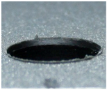 |  | 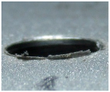 |
| Twist drill with 2 edges | 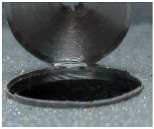 | 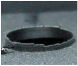 | 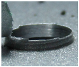 |
| Twist drill with 3 edges |  |  | 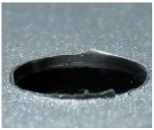 |
| Pilot hole 2 mm and Twist drill with 2 edges | 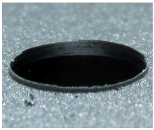 | 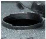 | 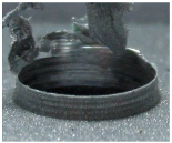 |
| Pilot hole 3 mm and Twist drill with 2 edges | 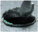 |  | 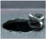 |
| Pilot hole 4 mm and Twist drill with 2 edges | 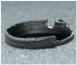 | 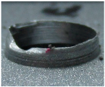 | 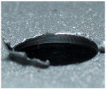 |
© 2016 by the authors; licensee MDPI, Basel, Switzerland. This article is an open access article distributed under the terms and conditions of the Creative Commons Attribution (CC-BY) license (http://creativecommons.org/licenses/by/4.0/).
Share and Cite
Rezende, B.A.; Silveira, M.L.; Vieira, L.M.G.; Abrão, A.M.; Faria, P.E.d.; Rubio, J.C.C. Investigation on the Effect of Drill Geometry and Pilot Holes on Thrust Force and Burr Height When Drilling an Aluminium/PE Sandwich Material. Materials 2016, 9, 774. https://doi.org/10.3390/ma9090774
Rezende BA, Silveira ML, Vieira LMG, Abrão AM, Faria PEd, Rubio JCC. Investigation on the Effect of Drill Geometry and Pilot Holes on Thrust Force and Burr Height When Drilling an Aluminium/PE Sandwich Material. Materials. 2016; 9(9):774. https://doi.org/10.3390/ma9090774
Chicago/Turabian StyleRezende, Bruna Aparecida, Michele L. Silveira, Luciano M. G. Vieira, Alexandre M. Abrão, Paulo Eustáquio de Faria, and Juan C. Campos Rubio. 2016. "Investigation on the Effect of Drill Geometry and Pilot Holes on Thrust Force and Burr Height When Drilling an Aluminium/PE Sandwich Material" Materials 9, no. 9: 774. https://doi.org/10.3390/ma9090774