Article

Experimental Investigation of Mechanical Properties of Black Shales after CO2-Water-Rock Interaction

1
Wuhan University, Wuhan 430072, China
2
Key Laboratory of Hubei Province for Water Jet Theory & New Technology, Wuhan 430072, China
3
Deep Earth Energy Laboratory, Department of Civil Engineering, Monash University, Melbourne 3800, Australia
*
Author to whom correspondence should be addressed.
Materials 2016, 9(8), 663; https://doi.org/10.3390/ma9080663
Submission received: 26 July 2016 / Revised: 2 August 2016 / Accepted: 3 August 2016 / Published: 6 August 2016
(This article belongs to the Special Issue Fracture and Fatigue Mechanics of Materials)

Abstract

:
The effects of CO2-water-rock interactions on the mechanical properties of shale are essential for estimating the possibility of sequestrating CO2 in shale reservoirs. In this study, uniaxial compressive strength (UCS) tests together with an acoustic emission (AE) system and SEM and EDS analysis were performed to investigate the mechanical properties and microstructural changes of black shales with different saturation times (10 days, 20 days and 30 days) in water dissoluted with gaseous/super-critical CO2. According to the experimental results, the values of UCS, Young’s modulus and brittleness index decrease gradually with increasing saturation time in water with gaseous/super-critical CO2. Compared to samples without saturation, 30-day saturation causes reductions of 56.43% in UCS and 54.21% in Young’s modulus for gaseous saturated samples, and 66.05% in UCS and 56.32% in Young’s modulus for super-critical saturated samples, respectively. The brittleness index also decreases drastically from 84.3% for samples without saturation to 50.9% for samples saturated in water with gaseous CO2, to 47.9% for samples saturated in water with super-critical carbon dioxide (SC-CO2). SC-CO2 causes a greater reduction of shale’s mechanical properties. The crack propagation results obtained from the AE system show that longer saturation time produces higher peak cumulative AE energy. SEM images show that many pores occur when shale samples are saturated in water with gaseous/super-critical CO2. The EDS results show that CO2-water-rock interactions increase the percentages of C and Fe and decrease the percentages of Al and K on the surface of saturated samples when compared to samples without saturation.

1. Introduction

Increasing attention has been given to the reduction of the emission of carbon dioxide (CO2), which contributes most of the greenhouse effect. Geological storage of CO2 is one of the most promising ways to mitigate global warming and climate change [1]. Shale gas reservoirs, which are characterized as having ultra low permeability and high storage potential, are suitable for CO2 sequestration [2,3,4].
As CO2 is injected into shale reservoirs, it dissolves into waters or brines and changes the acid-base equilibrium which triggers the dissolution and precipitation of minerals [5,6]. Ketzer et al. [7] observed the dissolution of feldspars and calcite cement and the precipitation of dickite, opal and calcite, and reported that the dissolution of Ca and Fe cations limited the precipitation of carbonate. Lu et al. [8] found that concentrations of cations in groundwater presented two trends, and all the concentration variations were dominated by the precipitation of carbonate minerals. Liu et al. [9] experimentally investigated the chemical reactions of shale in CO2 and brine saturation. Micro-scale observation revealed the dissolution of carbonates and feldspars, and the precipitation of carbonates and clay minerals. Similar dissolution and precipitation results have been presented by many other scholars [10,11,12,13,14,15].
The mineral dissolution and precipitation also cause changes of mechanical properties (e.g., deformation, strength) and hydrological properties (e.g., permeability and porosity) of rocks, which lead to risks for CO2 sequestration [16,17,18,19]. The variation of hydrological properties reflects to the change of microstructures in rocks which, of cause influence the mechanical properties. Bertier et al. [20] found that dissolution of ankerite/dolomite and Al-silicates increased the porosity/permeability of sandstones. Madland et al. [21] studied the mechanical stability of chalk after saturation with CO2 gas and carbonate water. The results showed that CO2 gas has less effect on chalk’s strength, while carbonate water leads to considerable decrease of strength. Bennion and Bachu [22] investigated the effect of acid gas (CO2 and H2S) on the relative permeability-displacement character of four kinds of rocks after injection into deep saline aquifers. Bachu and Bennion [23] also found that the capillary pressure, relative permeability and other displacement characteristics for samples in CO2-brine systems rely on the in situ conditions of pressure, temperature and water salinity. Farquhar et al. [24] tested the mineral and porosity variations of sandstones and siltstones after reacting in low-salinity water with super-critical carbon dioxide (SC-CO2). The results showed that the calcite content decreased from 17 vol % to 15 vol % after reaction, and an increase in porosity of 1.1 vol % CO2-water-rock interactions also cause caprock deformation, which results in the change of effective stress and stress-induced permeability [25,26,27,28]. Clearly, the effect of CO2-water-rock interactions on the mechanical properties of shale, especially stress behaviors and crack propagations, which lead to CO2 leakage in shale reservoirs, is unclear and needs further study.
A variety of shale samples were obtained to react with gaseous/super-critical CO2 in the medium of fresh water in several reactors. A group of uniaxial compressive strength (UCS) tests was conducted to obtain the strength variation. The crack propagations and micro-scale characteristics were recorded by acoustic emission (AE) sensors, ARAMIS digital cameras, and SEM, respectively. The purpose of this study is to improve our understanding of gaseous/super-critical CO2-water-rock interactions and help us to know more about the risks of CO2 sequestration.

2. Geological Setting and Geochemical Interactions

2.1. Geological Setting

Southeast Chongqing, which is located southeast of the Sichuan Basin, is part of the Upper Yangtze plate. Upper Paleozoic marine black shale (including Cambrian Niutitang Formation and Lower Silurian Longmaxi Formation) in these areas is characterized as having high thickness, suitable burial depth and effective fracture development [29,30]. The thickness of the black shales in south-east Chongqing varies from tens of meters to more than one hundred meters and it is distributed in areas like Fuling, Wulong, Pengshui and Shizhu, as shown in Figure 1. The total organic carbon (TOC) content and equivalent vitrinite reflectance (Ro) for Longmaxi shale are 2%–4% and 2.5%–3.0%, respectively. The Niutitang shale has a range of TOC content from 3% to 6% and equivalent Ro from 3% to 4% [31].
The samples used in the present study were Longmaxi black shales from Shizhu County. Shale outcrops were obtained from an extended shale layer from Pengshui, Chongqing. The mineral compositions obtained using a Bruker AXS D8-Focus X-ray diffractometer (Institute of Rock and Soil Mechanics, Chinese Academy of Sciences, Wuhan, China) are listed in Table 1.

2.2. Geochemical Interactions

Due to the dissolution of CO2 in water, the weak acid H2CO3 forms and the pH of the fluid decreases, as described by the following equation:
CO 2 ( a q ) + H 2 O H 2 CO 3 H + + HCO 3 2 H + + CO 3 2
When CO2 is injected into a shale reservoir, the underground high pressure and temperature cause the pH of the water to decrease dramatically. According to Toews et al. [32], the pH of water in equilibrium with CO2 is 2.84 when the temperature and pressure are 40 °C and 7 MPa, respectively. Ultra low pH will result in the dissolution of some minerals, including feldspar, calcite and pyrite [16,24,33].
However, the CO2-water-rock reaction is dependent on the environmental conditions [33]. According to Oomole and Osoba [34], higher CO2 pressure promotes the dissolution of carbonates, while lower pressure decelerates the dissolution, or accelerates carbonate precipitation. Wigand et al. [35] found that higher pressure and temperature enhance the dissolution of quartz. Iron concentration also influences the reaction [7,36].
Based on the mineral compositions of shale samples (see Table 1), likely reversible reactions are listed in Equations (2)–(5).
KAlSi 3 O 8 + 2 H + + H 2 O 2 K + + Al 2 Si 2 O 5 ( OH ) 4 + 4 SiO 2 ( a q ) K-Feldspar + 2 H + + H 2 O 2 K + + Kaolinite + 4 SiO 2 ( a q ) ,
CaCO 3 + H + Ca 2 + + HCO 3 Calcite + H + Ca 2 + + bicarbonate ,
Fe 2 + + HCO 3 FeCO 3 + H + Fe 2 + + bicarbonate siderite + H + ,
Fe 2 + + Mg 2 + + Ca 2 + + 3 HCO 3 CaFeMg ( CO 3 ) 3 + 3 H + Fe 2 + + Mg 2 + + Ca 2 + + bicarbonate mixed carbonate + 3 H + ,
Equations (2) and (3) present the reversible reactions that influence the dissolution of k-feldspar (Equation (3)) and calcite (Equation (4)). Equations (4) and (5) indicate the likely CO2 trapping in mineral through bicarbonate and cations. Kaolinite and pyrite will not dissolve in the CO2 equilibrium solution.

3. Experimental Methodology

3.1. Sample Preparation

Shale blocks were cored parallel to the beddings. The length of each sample was 60 mm, and the diameter was chosen as 30 mm to ensure a height-diameter ratio of 2:1. All the coring and grinding work was finished in the Institute of Rock and Soil Mechanics, Chinese Academy of Science, China, and the experiments were conducted in the Deep Earth Energy Laboratory in the Department of Civil Engineering at Monash University, Melbourne, Australia.
Twelve samples were divided into two groups and saturated in water in equilibrium with CO2 at pressures of 7 MPa (gaseous) and 9 MPa (super-critical), respectively. For each group, samples were saturated for different times (10 days, 20 days and 30 days). All the adsorbing conditions had the same temperature of 40 °C. The arrangement of saturation conditions is shown in Table 2. Two samples without saturation were set as the control group. Three slices (with a thickness of 0.4 mm), two of which were saturated together with samples in water with gaseous and super-critical CO2 for 30 days, were used for SEM tests.
The saturation system consists of five parts: CO2 cylinder, pump, valves, monitor system and container/heating system, as shown in Figure 2. A Model 500D syringe pump (Monash University, Melbourne, Australia) was used to refill CO2 into containers. The pressure was controlled by a Teledyne D-series pump controller (Monash University, Melbourne, Australia) with a precision of 1 kPa. The surface of the container was covered by electric resistance wires and the temperature could be adjusted from room temperature to 100 °C.

3.2. Testing Arrangement

Fourteen UCS tests were performed on shale samples after CO2-water-rock interactions. SHIMADZU AG 9 300 kN compression equipment (Monash University, Melbourne, Australia) was used to conduct the experiments. The loading rate was set at 0.1 mm/min for all the tests. The load and strain were recorded by an advanced data acquisition system. The crack propagations were recorded by acoustic emission (AE) sensors and ARAMIS 3-D technology. The microstructure and X-ray spectra were obtained by a JEOL FE 7001 SEM machine (Monash University, Melbourne, Australia) with a Brucker EDS detector at the Monash MCEM (Monash Centre for Electron Microscopy) center.

4. Results and Discussion

4.1. Microstructure Alteration after CO2-Water-Interaction

Mineralogical variations associated with microstructure alteration induced by water with gaseous/super-critical CO2 was investigated by SEM together with EDS analysis. 
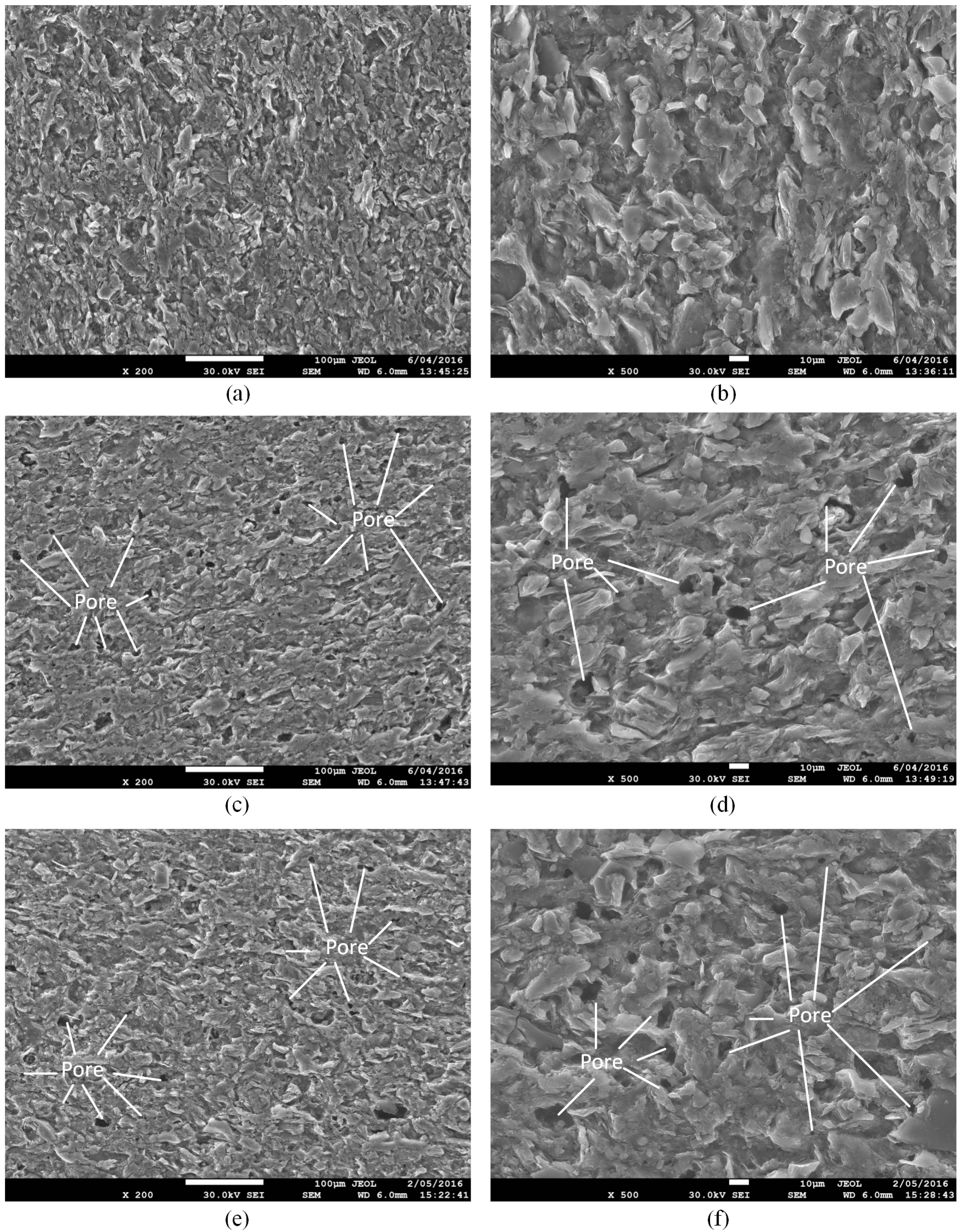
Figure 3 shows the microstructure of shale samples without any fluid saturation (a,b), samples with water + gaseous CO2 (c,d) and water + SC-CO2 saturation (e,f). It is clear that the saturation of water with both gaseous and super-critical CO2 creates many pores on the surface of the shale slice, possibly because the dissolution of CO2 in water decreases the pH of the fluid (Equation (1)), which may accelerate the chemical reactions for mineral dissolution (Equations (2) and (3)) and carbonate precipitation (Equations (4) and (5)). Although SEM can only observe the surface of the sample, we can deduce that, with long-term saturation, water, CO2 and ions in the fluids will penetrate into the matrix of the shale and create more pores inside. These pores will create a secondary porosity system, which decreases the strength of the natural pore structure, and the strength of the sample therefore decreases after saturation [37,38]. As SEM analysis can only concentrate on an ultra-small area of the slice’s surface, the difference of the effect of gaseous CO2 and SC-CO2 on the microstructure of shale samples is minor in the SEM images.
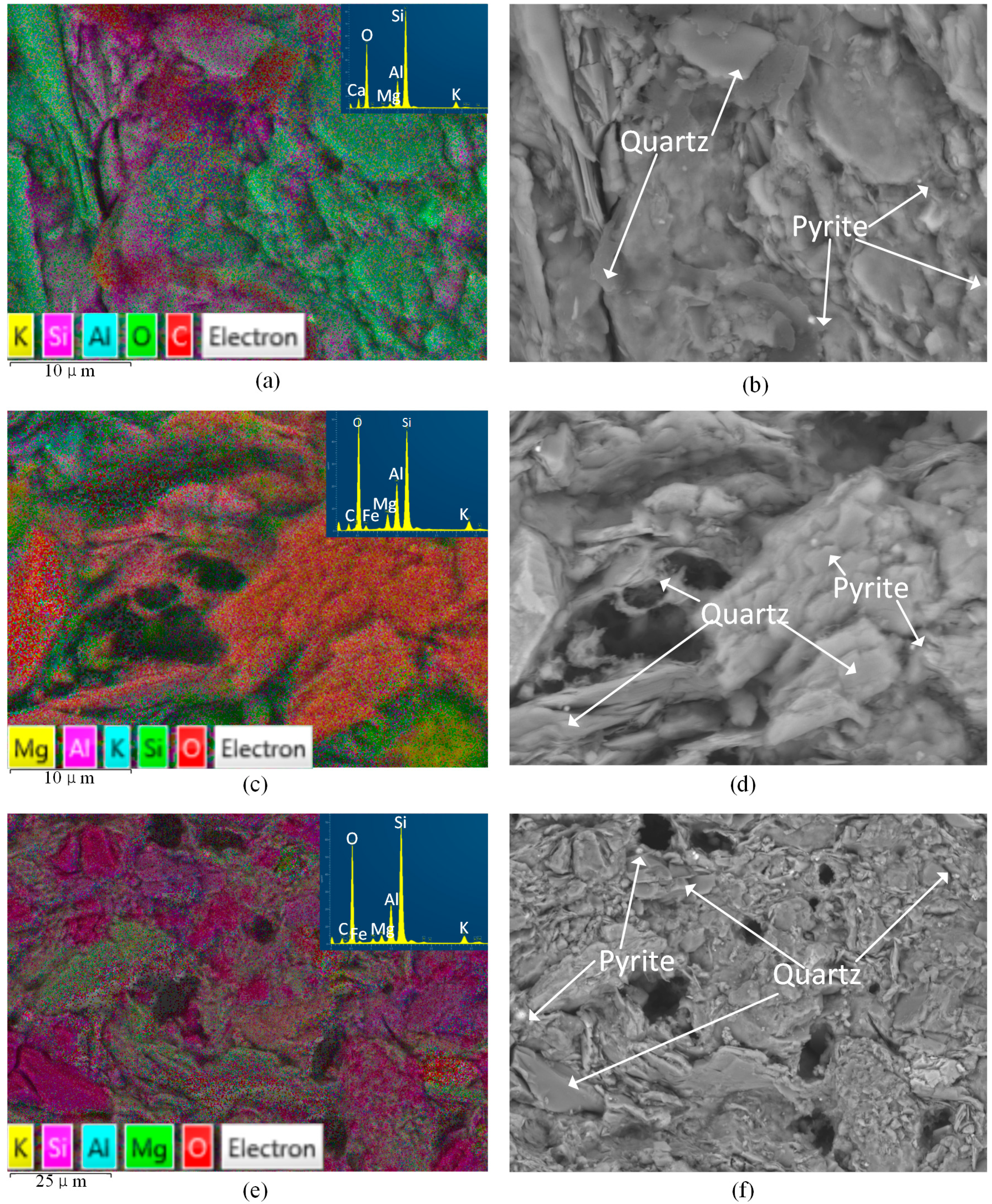
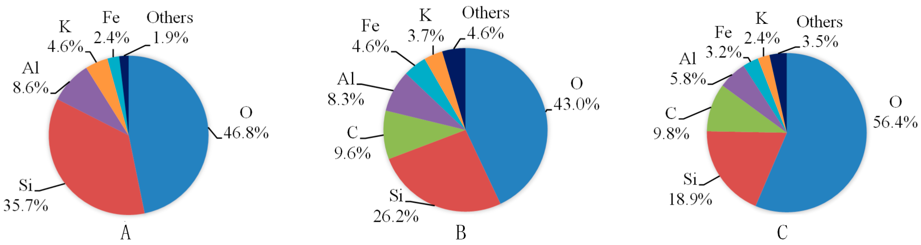
Figure 4 shows the EDS results of shale samples with or without fluid saturation. The X-ray spectra results are shown in Figure 5. For each slice, we observed three different areas and here present the one with a moderate percentage of carbon. From Figure 4 and Figure 5 we can see that oxygen and silica are the first and second highest proportion of all the elements of the three kinds of shale slices. For slices after saturation with water with gaseous CO2 and SC-CO2, carbon accounts for the third highest percentage of the elements, which are 9.6% and 9.8%, respectively. However, for samples without saturation, the percentage of carbon is negligible. This is mainly because the precipitation of carbonates attaches on the surface of the shale slice. As the gaseous and super-critical CO2 applied in the study have similar solubility and pH in water (shown in Table 4), they present similar percentages of carbon. Compared to the spectra of samples without saturation, ions like Al and K decrease and Fe increase in samples with water and CO2 saturation. This is caused by the dissolution of minerals, such as K-feldspar.

4.2. Effects of CO2-Water-Rock Interaction on Mechanical Behaviors

The variation of UCS and Young’s modulus of samples without saturation and samples saturated in water absorbed with gaseous and super-critical CO2 are shown in Table 3 and Figure 6. The standard deviations of UCS values and Young’s modulus for each saturation condition are minor, except for the two samples saturated in water with SC-CO2 for 30 days, which show large UCS variation. Considering the change of strength with saturation time, we chose the higher one for the purposes of discussion. For other groups, the average values are used in all discussions.
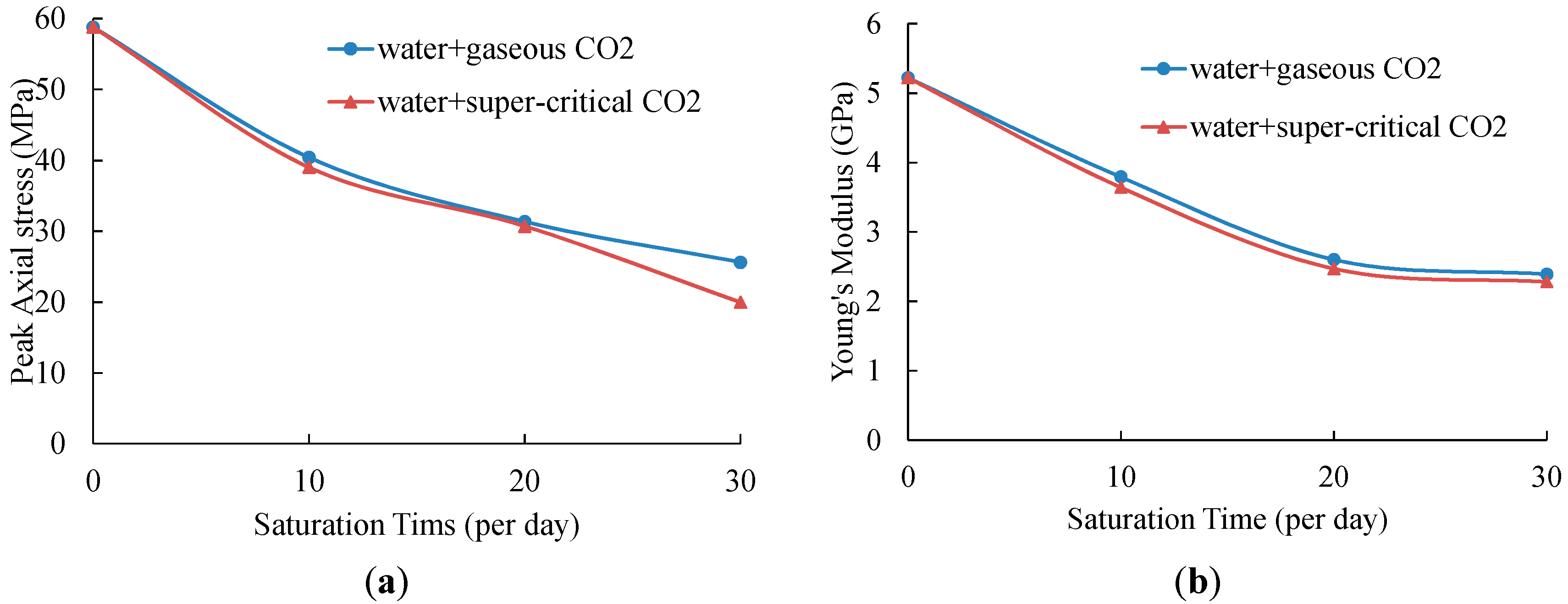
According to Table 3 and Figure 6, of all the tested samples, samples without saturation have the highest UCS and Young’s modulus values, of 58.82 MPa and 5.22 GPa, respectively. After 10-day saturation in water with gaseous CO2, the UCS value decreases to 40.42 MPa, and the Young’s modulus also shows a reduction of 27.39% to 3.79 GPa. When the saturation time is 20 days, samples show only 31.36 MPa strength and 2.60 GPa Young’s modulus, which is 46.48% and 49.81% respectively lower than samples with no saturation. For 10 more days of saturation, the UCS and Young’s modulus keeps decreasing and the values are smaller than half of that of samples without saturation, at 25.63 MPa and 2.39 GPa, respectively. For shale samples saturated in water with SC-CO2, the UCS values show reductions of 33.66%, 47.77% and 66.05% with saturation times of 10 days, 20 days and 30 days, respectively. The Young’s modulus also decreases dramatically from 5.22 GPa to 3.64 GPa (10-day saturation), 2.47 GPa (20-day saturation) and 2.28 GPa (30-day saturation), respectively.
The considerable reductions of strength and Young’s modulus for saturated samples are due to the CO2-water-rock interactions coupled with chemical and mechanical effects. When shale samples are saturated in gaseous/super-critical CO2 with the medium of fresh water, clays in the rock absorb water resulting in the shale swelling, which causes the decrease of strength and Young’s modulus [39]. According to Heller and Zoback [40] and Luo et al. [41], shale gas, which exists in natural fractures, porous matrices and kerogen, is easier to be replaced by CO2 as CO2 has better adsorption ability in shale [42]. Therefore, the adsorption of CO2 in shale samples will also cause shale swelling and strength decrease [43]. More importantly, the dissolution of CO2 in water leads to the chemical reactions for mineral dissolution (Equations (2) and (3)) and carbonate precipitation (Equations (4) and (5)). The dissolution and precipitation process creates pores in the rock, as shown in Figure 3, which changes the microstructure of shale samples. This phenomenon will contribute to the reduction of strength and Young’s modulus. Meanwhile, longer saturation time will cause greater damage on the shale sample, and the strength and Young’s modulus will therefore be lower. This is in accordance with the experimental results.
From Figure 6, we can see that the UCS and Young’s modulus values of samples saturated in water with gaseous and super-critical CO2 have the same variation trend with saturation time. However, with the same saturation time, both of the values of samples soaked in water + SC-CO2 fluids are smaller than those of samples soaked in water + gaseous CO2 fluids. The small discrepancies of strength and Young’s modulus are mainly caused by the difference of properties between gaseous CO2 and SC-CO2, as shown in Table 4. SC-CO2 has higher density, viscosity, thermal conductivity and dissolution ability in water than gaseous CO2. The pH of water dissoluted with these two fluids is similar, that of SC-CO2 based water being 2.83 and that of gaseous CO2 based water being 2.84. These differences overall contribute to the difference in results. Moreover, water, CO2 and ions under super-critical saturation conditions will more easily penetrate into shale samples than under gaseous saturation conditions because of the 2 MPa higher confining pressure.
Another important mechanical characteristic of reservoir rock is the brittleness index (BI). The brittleness index can be obtained by many methods, including mechanical analysis, energy analysis and mineral composition analysis [46]. In the present study, mechanical analysis was used for the calculation of the brittleness index (BI). It is defined by the following equation [47].
B I = reversible   strain total   strain
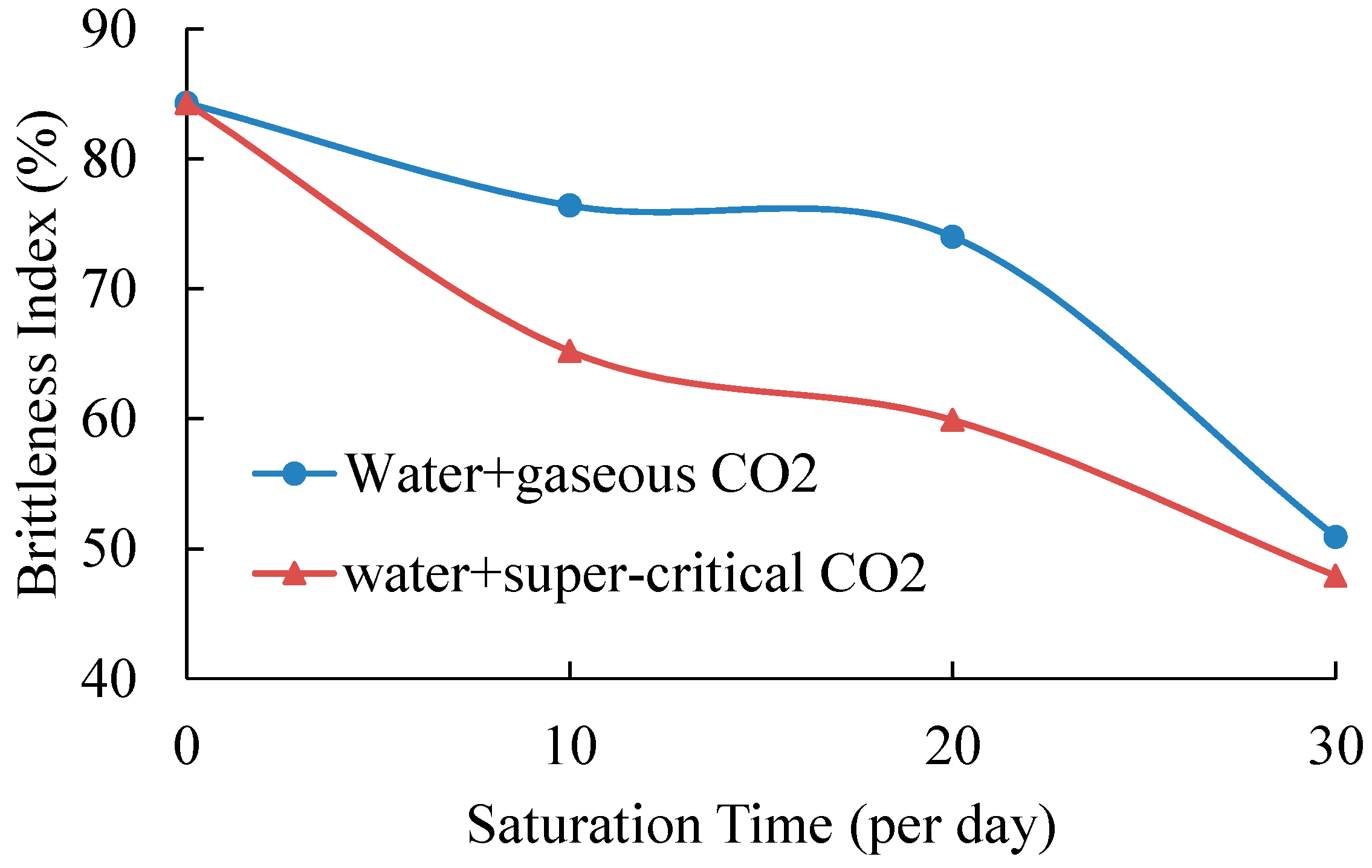
Table 5 shows the brittleness index of all tested samples and Figure 7 presents the variations of brittleness index with saturation time. The standard deviations of samples without saturation and samples saturated in gaseous/super-critical CO2 for 10 and 20 days are minor, varying from 1.2% to 3.8%. However, when the saturation time is 30 days, the samples saturated under gaseous conditions have a high standard deviation of 7.5%, and samples saturated under super-critical conditions have only one value (the other one is excluded because of the ultra-low UCS value). This means that samples with a longer saturation time will have larger variations in the brittleness index, which is caused by chemical-mechanical effects. However, the average value is still more reasonable for analysis.
According to Table 5 and Figure 7, samples without saturation have the highest brittleness index of 84.3%, which is consistent with the mineralogical analysis of samples that contain a high percentage of rigid components. After 10-day saturation, the values of samples in water with gaseous/super-critical CO2 decrease to 76.4% and 65.2%, respectively. This is mainly because the adsorption of water and CO2 and the chemical reactions of shale and fluids increase the plasticity and toughness. When the saturation time is 20 days, the brittleness index of both the two saturation conditions continues to increase. For samples saturated under gaseous conditions, the brittleness is 74.0%, slightly smaller than that of samples saturated under the same conditions for 10 days. Samples with SC-CO2 and water saturation present a much lower brittleness index of 59.9%. Compared to the results of 10-day saturation, 20-day saturation may create more cracks and pores in shale samples, which cause shale samples to have higher plasticity. When the saturation time is extended to 30 days, both kinds of saturated samples present higher axial strains than those with a shorter saturation time before failure, and their brittleness index decreases to 50.9% and 47.9%, respectively. The discrepancy of physical properties (Table 4) between gaseous and super-critical CO2 has less effect on shale strength and Young’s modulus. However, their influence on shale’s brittleness index is considerable. Samples with SC-CO2 and water saturation present a lower brittleness index than that of samples saturated in gaseous CO2 and water fluids for all three saturation times. This means that the beneficial properties of SC-CO2 decrease shale’s brittleness and increase its plasticity.

4.3. Effects of CO2-Water-Rock Interaction on Crack Propagation

With the benefits of high sensitivity and non-destructive monitoring, AE analysis is a widely used method to investigate the stages of crack closure, crack initiation and crack damage in rock mechanics studies and engineering applications [37,48]. The crack closure stage is characterized by very small AE energy, which is released by seating and loading adjustment. With the increase of axial load, stable crack growth or dilation occurs and the AE energy increases gradually, leading to the beginning of crack initiation. When rock samples reach the crack damage point, the AE energy increases drastically and the unstable crack growth creates considerable damage and samples finally fail. Hence, AE analysis provides an additional way to manifest rock mechanics during UCS tests. 
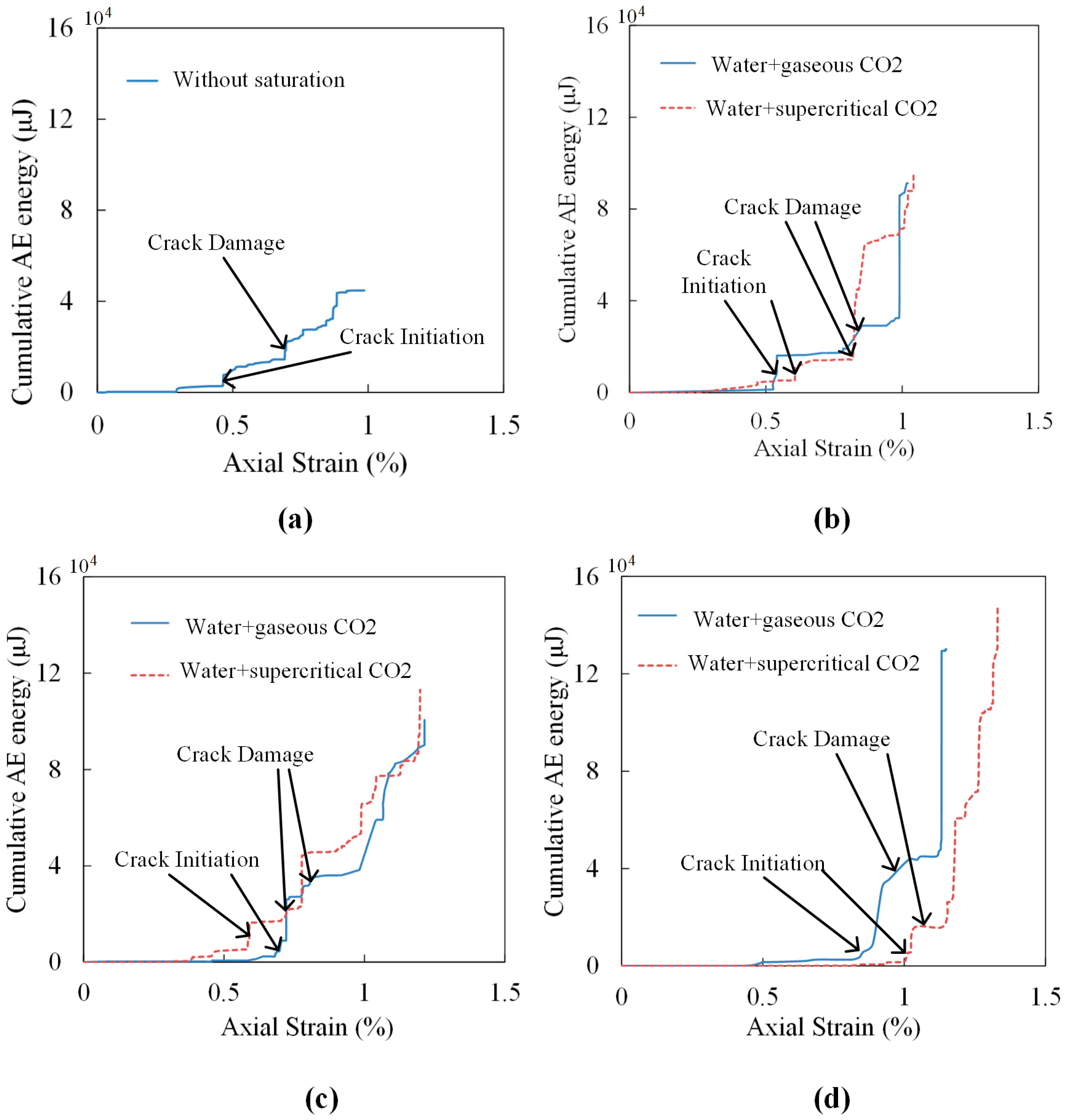
Figure 8 shows the variation of cumulative AE energy with axial strain for all kinds of saturated samples. As each group has two samples, here we present only one of the AE results for each saturation condition. The cumulative AE energy and axial stress for samples on both crack initiation and crack damage and the peak cumulative AE energy are listed in Table 6.
According to Figure 8 and Table 6, samples with longer saturation time show higher axial strain when failure occurs. This is mainly because of the swelling of samples caused by water and CO2 adsorption, and the occurrence of pores and cracks causes samples to have higher strain variations. This also indicates that CO2 saturation decreases sample brittleness and increases its plasticity. When samples reach the crack initiation point, their values of cumulative AE energy are low, accounting for a small amount of the peak value ranging from 1.4% to 6.4%. A sample without saturation has the highest axial stress at this point, which is 23.36 MPa. The axial stress for samples saturated in gaseous CO2 and water increase with the increase of saturation time, and the corresponding proportion of peak axial stress increases from 31.6% to 77.2%. For samples saturated under super-critical conditions, the axial stress decreases with the extension of saturation time. However, the proportion of axial stress on peak stress increases with increased saturation time, meaning that samples after gaseous/super-critical CO2 and water saturation require a higher percentage of peak UCS value to reach the crack initiation when the saturation time is longer. From Figure 8, we can also observe that samples saturated under gaseous conditions reach crack initiation faster than under super-critical conditions when the saturation durations are 10 days and 30 days. In contrast, for 20-day saturation, the trend is reversed. Samples saturated in water with SC-CO2 reach the crack damage point earlier than samples saturated in water with gaseous CO2 in 20 days. However, when saturation durations are 10 days and 30 days, the crack damage points are almost the same for both kinds of saturated samples. The reason for this difference is mainly because shale samples are anisotropic. When samples reach to the crack damage point, the cumulative AE energy increases to a higher level, ranging from 10.6%–38.2% on peak cumulative AE energy.
According to Figure 8, Table 3 and Table 6, peak cumulative AE energy shows a negative correlation with the UCS values. A sample without saturation has the lowest peak cumulative AE energy of 44,802 μJ. For samples saturated in water with gaseous/super-critical CO2, the peak cumulative AE energy increases with increasing saturation time. Specifically, with 10 days’ saturation, the values for samples under gaseous and super-critical conditions doubled and reached 91,227 μJ and 94,840 μJ, respectively. After 20- and 30-day saturation, the values of peak cumulative AE energy were 100,564 μJ and 130,037 μJ for samples under gaseous conditions, and 116,068 μJ and 147,862 μJ for samples under super-critical conditions, respectively. This phenomenon is mainly caused by several reasons. Firstly, the adsorption of water and CO2 increases the conductivity of AE emissions. Meanwhile, the swelling caused by water and CO2 adsorption creates more artificial fractures. The propagation of these fractures creates more AE energy. In addition, carbonates created by the precipitation process are crushed during the UCS tests and generate acoustic emissions. More importantly, according to the SEM results in Figure 3, the numerous pores produced by chemical reactions decrease the brittleness and increase the plasticity of samples. Therefore, after the peak strength point, samples with CO2 saturation can still bear load and create AE energy.

5. Conclusions

A series of UCS tests was conducted on samples without saturation, and samples saturated in water with gaseous/super-critical CO2 for different periods of time. AE and SEM analyses were performed to evaluate the influence of gaseous/super-critical CO2-water-rock interactions and different saturation times on the mechanical properties of Chinese black shale. Several detailed conclusions can be drawn as follows:
Gaseous/super-critical CO2-water rock interactions weaken the mechanical properties of shale, and the reductions of UCS, Young’s modulus and brittleness index are closely related to the saturation time. With a saturation time of 10 days, water with gaseous CO2 can cause reductions of 31.28% of UCS and 27.39% of Young’s modulus, while water with SC-CO2 causes UCS and Young’s modulus decreases of 33.66% and 30.27%, respectively. By extending the saturation time to 30 days, the UCS and Young’s modulus show reductions of 56.43% and 54.21% for water with gaseous CO2 saturation, and 66.05% and 56.32% for water with SC-CO2 saturation, respectively. The brittleness also decreases with increased saturation time. After 30-day saturation, the value decreases from 84.3% for samples without saturation to 50.9 for samples saturated under gaseous conditions, to 47.9% for samples saturated under super-critical conditions. The decrease of mechanical properties is partially due to the CO2-water-rock interactions, which dissolute mineral components and precipitate carbonates. Because of the small gap of physical properties, the effect of the different phase of CO2 on shale’s UCS and Young’s modulus is minor.
The saturation of water with gaseous/super-critical CO2 increases the total cumulative AE energy of shale samples, which shows a positive correlation with saturation time. Longer saturation time creates higher axial strain when failure occurs. For samples without saturation, the peak cumulative AE energy is 44,802 μJ. After 10 days’ saturation in water with gaseous CO2, the value increases to 91,227 μJ, which is smaller than for 30-day saturation. Samples saturated in water with SC-CO2 show a similar trend. However, the peak cumulative AE energy for super-critical saturation is slightly higher than that under gaseous saturation when the saturation time is the same.
Based on the SEM results, many pores occur on the surface of shale samples after 30-day saturation in water with gaseous/super-critical CO2. EDS analysis shows that CO2-water-rock interactions increase the percentages of C and Fe and decrease the percentages of K and Al on the surface of saturated samples. The changes of microstructure and chemical elements indicate the decrease in mechanical properties of saturated samples.
CO2 sequestration is a long-term program. However, in this study, we can only propose some short-term rules for CO2-water-rock interactions. Therefore, for a better understanding of the effects of CO2-water-rock interactions on shale’s mechanical properties, experiments with a much longer saturation time are necessary.

Acknowledgments

All the work reported in the study was financially supported by the National Key Basic Research Program of China (Grant no.: 2014CB239203) and the National Natural Science Foundation of China (Project No. 51179134, No. 11472197 and No. 51576143). The authors acknowledge the use of the facilities within the Monash Centre for Electron Microscopy.

Author Contributions

Xinping Long and Pathegama Gamage Ranjith conceived and designed the experiments; Qiao Lyu performed the experiments and analyzed the data; Bin Ji and Pathegama Gamage Ranjith contributed reagents/materials/analysis tools; Qiao Lyu wrote the paper.

Conflicts of Interest

The authors declare no conflict of interest.

References

  1. Bachu, S.; Bonijoly, D.; Bradshaw, J.; Burruss, R.; Holloway, S.; Christensen, N.P.; Mathiassen, O.M. CO2 storage capacity estimation: Methodology and gaps. Int. J. Greenh. Gas Control 2007, 1, 430–443. [Google Scholar] [CrossRef]
  2. Dahaghi, A.K. Numerical simulation and modeling of enhanced gas recovery and CO2 sequestration in shale gas reservoirs: A feasibility study. In Proceedings of the SPE International Conference on CO2 Capture, Storage, and Utilization, New Orleans, LA, USA, 10–12 November 2010.
  3. Liu, F.; Ellett, K.; Xiao, Y.; Rupp, J.A. Assessing the feasibility of CO2 storage in the New Albany Shale (Devonian-Mississippian) with potential enhanced gas recovery using reservoir simulation. Int. J. Greenh. Gas Control 2013, 17, 111–126. [Google Scholar] [CrossRef]
  4. Chen, Z.; Liao, X.; Zhao, X.; Feng, X.; Zang, J.; He, L. A new analytical method based on pressure transient analysis to estimate carbon storage capacity of depleted shales: A case study. Int. J. Greenh. Gas Control 2015, 42, 46–58. [Google Scholar] [CrossRef]
  5. Gunter, W.; Wiwehar, B.; Perkins, E. Aquifer disposal of CO2-rich greenhouse gases: Extension of the time scale of experiment for CO2-sequestering reactions by geochemical modelling. Mineral. Petrol. 1997, 59, 121–140. [Google Scholar] [CrossRef]
  6. Carroll, S.A.; McNab, W.W.; Dai, Z.; Torres, S.C. Reactivity of Mount Simon sandstone and the Eau Claire shale under CO2 storage conditions. Environ. Sci. Technol. 2012, 47, 252–261. [Google Scholar] [CrossRef] [PubMed]
  7. Ketzer, J.; Iglesias, R.; Einloft, S.; Dullius, J.; Ligabue, R.; De Lima, V. Water-rock-CO2 interactions in saline aquifers aimed for carbon dioxide storage: Experimental and numerical modeling studies of the Rio Bonito Formation (Permian), southern Brazil. Appl. Geochem. 2009, 24, 760–767. [Google Scholar] [CrossRef]
  8. Lu, J.; Partin, J.W.; Hovorka, S.D.; Wong, C. Potential risks to freshwater resources as a result of leakage from CO2 geological storage: A batch-reaction experiment. Environ. Earth. Sci. 2010, 60, 335–348. [Google Scholar] [CrossRef]
  9. Liu, F.; Lu, P.; Griffith, C.; Hedges, S.W.; Soong, Y.; Hellevang, H.; Zhu, C. CO2–brine–caprock interaction: Reactivity experiments on Eau Claire shale and a review of relevant literature. Int. J. Greenh. Gas Control 2012, 7, 153–167. [Google Scholar] [CrossRef]
  10. Choi, B.-Y.; Yun, S.-T.; Mayer, B.; Hong, S.-Y.; Kim, K.-H.; Jo, H.-Y. Hydrogeochemical processes in clastic sedimentary rocks, South Korea: A natural analogue study of the role of dedolomitization in geologic carbon storage. Chem. Geol. 2012, 306, 103–113. [Google Scholar] [CrossRef]
  11. Chopping, C.; Kaszuba, J.P. Supercritical carbon dioxide-brine-rock reactions in the Madison Limestone of Southwest Wyoming: An experimental investigation of a sulfur-rich natural carbon dioxide reservoir. Chem. Geol. 2012, 322, 223–236. [Google Scholar] [CrossRef]
  12. Choi, B.-Y.; Yun, S.-T.; Kim, K.-H.; Choi, H.-S.; Chae, G.-T.; Lee, P.-K. Geochemical modeling of CO2-water-rock interactions for two different hydrochemical types of CO2-rich springs in Kangwon District, Korea. J. Geochem. Explor. 2014, 144, 49–62. [Google Scholar] [CrossRef]
  13. Wang, T.; Wang, H.; Zhang, F.; Xu, T. Simulation of CO2-water-rock interactions on geologic CO2 sequestration under geological conditions of China. Mar. Pollut. Bull. 2013, 76, 307–314. [Google Scholar] [CrossRef] [PubMed]
  14. Pokrovsky, O.S.; Golubev, S.V.; Schott, J.; Castillo, A. Calcite, dolomite and magnesite dissolution kinetics in aqueous solutions at acid to circumneutral pH, 25 to 150 C and 1 to 55 atm pCO2: New constraints on CO2 sequestration in sedimentary basins. Chem. Geol. 2009, 265, 20–32. [Google Scholar] [CrossRef]
  15. Pauwels, H.; Gaus, I.; le Nindre, Y.M.; Pearce, J.; Czernichowski-Lauriol, I. Chemistry of fluids from a natural analogue for a geological CO2 storage site (Montmiral, France): Lessons for CO2-water-rock interaction assessment and monitoring. Appl. Geochem. 2007, 22, 2817–2833. [Google Scholar] [CrossRef]
  16. Gaus, I. Role and impact of CO2-rock interactions during CO2 storage in sedimentary rocks. Int. J. Greenh. Gas Control 2010, 4, 73–89. [Google Scholar] [CrossRef]
  17. Harvey, O.R.; Qafoku, N.P.; Cantrell, K.J.; Lee, G.; Amonette, J.E.; Brown, C.F. Geochemical implications of gas leakage associated with geologic CO2 storage: A qualitative review. Environ. Sci. Technol. 2012, 47, 23–36. [Google Scholar] [CrossRef] [PubMed]
  18. Krevor, S.; Pini, R.; Zuo, L.; Benson, S.M. Relative permeability and trapping of CO2 and water in sandstone rocks at reservoir conditions. Water Resour. Res. 2012, 48, W02535–W02551. [Google Scholar] [CrossRef]
  19. Lyu, Q.; Long, X.; Ranjith, P.G.; Kang, Y. Unconventional Gas: Experimental Study of the Influence of Subcritical Carbon Dioxide on the Mechanical Properties of Black Shale. Energies 2016, 9, 516. [Google Scholar] [CrossRef]
  20. Bertier, P.; Swennen, R.; Laenen, B.; Lagrou, D.; Dreesen, R. Experimental identification of CO2-water-rock interactions caused by sequestration of CO2 in Westphalian and Buntsandstein sandstones of the Campine Basin (NE-Belgium). J. Geochem. Explor. 2006, 89, 10–14. [Google Scholar] [CrossRef] [Green Version]
  21. Madland, M.V.; Finsnes, A.; Alkafadgi, A.; Risnes, R.; Austad, T. The influence of CO2 gas and carbonate water on the mechanical stability of chalk. J. Petrol. Sci. Eng. 2006, 51, 149–168. [Google Scholar] [CrossRef]
  22. Bennion, B.; Bachu, S. Drainage and imbibition relative permeability relationships for supercritical CO2/brine and H2S/brine systems in intergranular sandstone, carbonate, shale, and anhydrite rocks. SPE Reserv. Eval. Eng. 2008, 11, 487–496. [Google Scholar] [CrossRef]
  23. Bachu, S.; Bennion, B. Effects of in-situ conditions on relative permeability characteristics of CO2-brine systems. Environ. Geol. 2008, 54, 1707–1722. [Google Scholar] [CrossRef]
  24. Farquhar, S.; Pearce, J.; Dawson, G.; Golab, A.; Sommacal, S.; Kirste, D.; Biddle, D.; Golding, S. A fresh approach to investigating CO2 storage: Experimental CO2-water-rock interactions in a low-salinity reservoir system. Chem. Geol. 2015, 399, 98–122. [Google Scholar] [CrossRef]
  25. Rutqvist, J.; Wu, Y.-S.; Tsang, C.-F.; Bodvarsson, G. A modeling approach for analysis of coupled multiphase fluid flow, heat transfer, and deformation in fractured porous rock. Int. J. Rock Mech. Min. 2002, 39, 429–442. [Google Scholar] [CrossRef]
  26. Rutqvist, J.; Birkholzer, J.; Tsang, C.-F. Coupled reservoir-geomechanical analysis of the potential for tensile and shear failure associated with CO2 injection in multilayered reservoir-caprock systems. Int. J. Rock Mech. Min. 2008, 45, 132–143. [Google Scholar] [CrossRef]
  27. Rutqvist, J.; Vasco, D.W.; Myer, L. Coupled reservoir-geomechanical analysis of CO2 injection and ground deformations at In Salah, Algeria. Int. J. Greenh. Gas Control 2010, 4, 225–230. [Google Scholar] [CrossRef]
  28. Rutqvist, J.; Tsang, C.-F. A study of caprock hydromechanical changes associated with CO2-injection into a brine formation. Environ. Geol. 2002, 42, 296–305. [Google Scholar] [CrossRef]
  29. Xie, C.; Zhang, J.; Li, Y.; Wang, X. Characteristics and gas content of the Lower Cambrian dark shale in Well Yuke 1, Southeast Chongqing. Oil Gas Geol. 2013, 1, 4. [Google Scholar]
  30. Tian, H.; Pan, L.; Xiao, X.; Wilkins, R.W.; Meng, Z.; Huang, B. A preliminary study on the pore characterization of Lower Silurian black shales in the Chuandong Thrust Fold Belt, southwestern China using low pressure N2 adsorption and FE-SEM methods. Mar. Petrol. Geol. 2013, 48, 8–19. [Google Scholar] [CrossRef]
  31. Pan, L.; Xiao, X.; Tian, H.; Zhou, Q.; Cheng, P. Geological models of gas in place of the Longmaxi shale in Southeast Chongqing, South China. Mar. Petrol. Geol. 2016, 73, 433–444. [Google Scholar] [CrossRef]
  32. Toews, K.L.; Shroll, R.M.; Wai, C.M.; Smart, N.G. pH-defining equilibrium between water and supercritical CO2. Influence on SFE of organics and metal chelates. Anal. Chem. 1995, 67, 4040–4043. [Google Scholar] [CrossRef]
  33. Watson, M. Petrological Characterisation of the Vlaming Sub-Basin, Perth Basin for the Purpose of CO2 Storage; CO2CRC Publication Number RPT06-0098; CO2CRC: Melbourne, Australia, 2006. [Google Scholar]
  34. Oomole, O.; Osoba, J. Carbon dioxide-dolomite rock interaction during CO flooding process. In Proccedings of the Annual Technical Meeting, Banff, AB, Canada, 10–13 May 1983.
  35. Wigand, M.; Carey, J.; Schütt, H.; Spangenberg, E.; Erzinger, J. Geochemical effects of CO2 sequestration in sandstones under simulated in situ conditions of deep saline aquifers. Appl. Geochem. 2008, 23, 2735–2745. [Google Scholar] [CrossRef]
  36. Krauskopf, K.B.; Bird, D.K. Introduction to Geochemistry; McGraw-Hill New York: New York, NY, USA, 1967; Volume 721. [Google Scholar]
  37. Rathnaweera, T.; Ranjith, P.; Perera, M.; Haque, A.; Lashin, A.; Al Arifi, N.; Chandrasekharam, D.; Yang, S.; Xu, T.; Wang, S. CO2-induced mechanical behaviour of Hawkesbury sandstone in the Gosford basin: An experimental study. Mater. Sci. Eng. A 2015, 641, 123–137. [Google Scholar] [CrossRef]
  38. Marbler, H.; Erickson, K.P.; Schmidt, M.; Lempp, C.; Pöllmann, H. Geomechanical and geochemical effects on sandstones caused by the reaction with supercritical CO2: An experimental approach to in situ conditions in deep geological reservoirs. Environ. Earth Sci. 2013, 69, 1981–1998. [Google Scholar] [CrossRef]
  39. Lyu, Q.; Ranjith, P.; Long, X.; Kang, Y.; Huang, M. A review of shale swelling by water adsorption. J. Nat. Gas Sci. Eng. 2015, 27, 1421–1431. [Google Scholar] [CrossRef]
  40. Heller, R.; Zoback, M. Adsorption of methane and carbon dioxide on gas shale and pure mineral samples. J. Unconv. Oil Gas Resour. 2014, 8, 14–24. [Google Scholar] [CrossRef]
  41. Luo, X.; Wang, S.; Wang, Z.; Jing, Z.; Lv, M.; Zhai, Z.; Han, T. Adsorption of methane, carbon dioxide and their binary mixtures on Jurassic shale from the Qaidam Basin in China. Int. J. Coal. Geol. 2015, 150–151, 210–223. [Google Scholar] [CrossRef]
  42. Middleton, R.S.; Carey, J.W.; Currier, R.P.; Hyman, J.D.; Kang, Q.; Karra, S.; Jiménez-Martínez, J.; Porter, M.L.; Viswanathan, H.S. Shale gas and non-aqueous fracturing fluids: Opportunities and challenges for supercritical CO2. Appl. Energy 2015, 147, 500–509. [Google Scholar] [CrossRef]
  43. De Jong, S.M.; Spiers, C.J.; Busch, A. Development of swelling strain in smectite clays through exposure to carbon dioxide. Int. J. Greenh. Gas Control 2014, 24, 149–161. [Google Scholar] [CrossRef]
  44. Span, R.; Wagner, W. A new equation of state for carbon dioxide covering the fluid region from the triple-point temperature to 1100 K at pressures up to 800 MPa. J. Phys. Chem. Ref. Data 1996, 25, 1509–1596. [Google Scholar] [CrossRef]
  45. Hou, D.; Luo, P.; Wang, C.; Sun, L.; Tang, Y.; Pan, Y. Experimental research and theoretical model for CO2 solubility in water under high temperature and high pressure. J. Jilin Univ. Earth Ed. 2015, 45, 564–572. [Google Scholar]
  46. Zhang, D.; Ranjith, P.; Perera, M. The brittleness indices used in rock mechanics and their application in shale hydraulic fracturing: A review. J. Petrol. Sci. Eng. 2016, 143, 158–170. [Google Scholar] [CrossRef]
  47. Hucka, V.; Das, B. International Journal of Rock Mechanics and Mining Sciences & Geomechanics Abstracts. In Brittleness Determination of Rocks by Different Methods; Elsevier: Amsterdam, The Newtherlands, 1974; pp. 389–392. [Google Scholar]
  48. Lyu, Q.; Ranjith, P.; Long, X.; Kang, Y.; Huang, M. Effects of coring directions on the mechanical properties of Chinese shale. Arab. J. Geosci. 2015, 8, 10289–10299. [Google Scholar] [CrossRef]
Figure 1. A sketch map of Lower Silurian Longmaxi shale in Southeast Chongqing.
Materials 09 00663 g001
Figure 2. High-pressure adsorbing system.
Materials 09 00663 g002
Figure 3. SEM images of of samples without saturation (a,b); samples with water + gaseous CO2 saturation (c,d) and samples with water + super-critical CO2 saturation (e,f). (a,c,e) have a magnification of 200×; (b,d,f) have a magnification of 500×.
Materials 09 00663 g003
Figure 4. EDS images of samples without saturation and samples with water and gaseous/super-critical CO2 saturation. (a,c,e) are chemical mapping and X-ray spectra; (b,d,f) are compacted SEM results.
Materials 09 00663 g004
Figure 5. Chemical element composition by EDS analysis. (A) is for sample without saturation; (B) is for sample with water and gaseous CO2 saturation and (C) is for sample with water and SC-CO2 saturation.
Materials 09 00663 g005
Figure 6. Variation of UCS (a) and Young’s modulus (b).
Materials 09 00663 g006
Figure 7. Variations of brittleness index for shale samples.
Materials 09 00663 g007
Figure 8. Variation of cumulative AE energy with axial strain for sample without saturation (a), samples saturated in gaseous and super-critical CO2 for 10 days (b); 20 days (c) and 30 days (d).
Materials 09 00663 g008
Table 1. Mineral composition of shale samples.
Mineralogical AnalysisValue (%, w/w)Chemistry
Quartz58.38SiO2
Potassium Feldspar14.57KAlSi3O8
Muscovite5.57KAl2(Si3AlO10)
Calcite9.54CaCO₃
Pyrite4.08FeS2
Smectite3.43(Al,Mg)2[Si4O10](OH)2·nH2O
Illite1.42K1.5Al4(Si6.5Al1.5O20)(OH)4
Annite1.41--
Kaolinite1.00Al2Si2O5(OH)4
Braunite0.37--
Table 2. Saturation arrangements.
Experimental StageStage Duration (Days)Pressure (MPa)Temperature (°C)Number of Samples
Without saturation------2
Gaseous107402
207402
307402
Super-critical109402
209402
309402
Table 3. Values of uniaxial compressive strength (UCS) and Young’s modulus (E) for all tested samples.
SpecimenUCS, MPaAverage UCS, MPa (Standard Deviation, MPa)∆UCS, %Young’s Modulus, GPaAverage E, GPa (Standard Deviation, GPa)E, %
Without saturationNO. 156.3358.82 (2.49)5.415.22 (0.20)
NO. 261.315.02
Gaseous CO2 + water10 days
NO. 137.8540.42 (2.57)31.28%3.613.79 (0.18)27.39%
NO. 242.983.96
20 days
NO. 129.5531.36 (1.81)46.68%2.442.60 (0.16)49.81%
NO. 233.162.76
30 days
NO. 123.4925.63 (2.14)56.43%2.232.39 (0.16)54.21%
NO. 227.762.54
Super-critical CO2 + water10 days
NO. 137.4239.02 (1.60)33.66%3.453.64 (0.19)30.27%
NO. 240.623.83
20 days
NO. 127.5530.72 (3.17)47.77%2.252.47 (0.22)52.68%
NO. 233.892.69
30 days
NO. 119.9719.9766.05%2.282.2856.32%
NO. 29.35 (excluded)--
Table 4. Comparison of physical properties of gaseous CO2 (7 MPa, 40 °C) and SC-CO2 (9 MPa, 40 °C) and their dissolution abilities in water [32,44,45].
PropertiesPhaseDensity kg/m3Viscosity μPa·sThermal Conductivity W/m·KDissolution in Water dm3/kgpH of Water
Gaseous CO2Vapor198.5519.2880.03126.232.84 ± 0.02
SC-CO2Super-critical492.7535.3600.07127.812.83 ± 0.02
Table 5. Brittleness index for samples with different saturation conditions.
Saturation ConditionSaturation Time/Days
0102030
BI %Average % (Standard Deviation)BI %Average % (Standard Deviation)BI %Average % (Standard Deviation)BI %Average % (Standard Deviation)
Without saturation83.184.3 (1.2)
85.4
Gaseous79.876.4 (3.4)75.674.0 (1.7)43.450.9 (7.5)
73.072.358.3
Super-critical68.265.2 (3.0)62.559.9 (2.6)47.947.9
62.257.3
Table 6. Crack propagation threshold values of stress and cumulative energy release from AE results.
Saturation ConditionCrack Initiation (% of peak)Crack Damage (% of peak)Peak Cumulative AE Energy μJ
Cumulative AE Energy μJ (% of peak)Axial Stress MPa (% of peak)Cumulative AE Energy μJ (% of peak)Axial Stress MPa (% of peak)
Without saturation2864 (6.4)23.36 (39.7)14,511 (32.4)44.15 (75.1)44,802
Gaseous10 days1377 (1.5)12.77 (31.6)17,518 (19.2)26.52 (65.6)91,227
20 days2347 (2.3)15.76 (50.3)38,369 (38.2)21.93 (70.0)100,564
30 days3578 (2.8)19.79 (77.2)46,995 (36.1)22.09 (86.2)130,037
Super-critical10 days5306 (5.6)18.86 (48.3)14,526 (15.3)31.57 (80.9)94,840
20 days5306 (4.6)16.40 (53.4)23,395 (20.2)26.48 (86.2)116,068
30 days2039 (1.4)14.29 (71.5)15,745 (10.6)19.13 (95.8)147,862

