Article

Effect of Chromium on Corrosion Behavior of P110 Steels in CO2-H2S Environment with High Pressure and High Temperature

School of Mechanical and Electronic Engineering, China University of Petroleum, Qingdao 266580, China
*
Author to whom correspondence should be addressed.
Materials 2016, 9(3), 200; https://doi.org/10.3390/ma9030200
Submission received: 22 January 2016 / Revised: 5 March 2016 / Accepted: 8 March 2016 / Published: 16 March 2016

Abstract

:
The novel Cr-containing low alloy steels have exhibited good corrosion resistance in CO2 environment, mainly owing to the formation of Cr-enriched corrosion film. In order to evaluate whether it is applicable to the CO2 and H2S coexistence conditions, the corrosion behavior of low-chromium steels in CO2-H2S environment with high pressure and high temperature was investigated using weight loss measurement and surface characterization. The results showed that P110 steel suffered localized corrosion and both 3Cr-P110 and 5Cr-P110 steels exhibited general corrosion. However, the corrosion rate of 5Cr-P110 was the highest among them. The corrosion process of the steels was simultaneously governed by CO2 and H2S. The outer scales on the three steels mainly consisted of FeS1−x crystals, whereas the inner scales on Cr-containing steels comprised of amorphous FeS1−x, Cr(OH)3 and FeCO3, in contrast with the amorphous FeS1−x and FeCO3 mixture film of P110 steel. The more chromium the steel contains, the more chromium compounds the corrosion products contain. The addition of chromium in steels increases the uniformity of the Cr-enriched corrosion scales, eliminates the localized corrosion, but cannot decrease the general corrosion rates. The formation of FeS1−x may interfere with Cr-enriched corrosion scales and lowering the corrosion performance of 3Cr-P110 and 5Cr-P110 steels.

1. Introduction

The CO2/H2S corrosion problems of oil country tubular goods (OCTG) become increasingly prominent with the exploitation of oil and gas field under high temperature and high CO2 and/or H2S pressure [1,2,3,4,5,6]. Corrosion resistant alloys (CRAs), such as stainless steels and high-nickel alloys, have been developed to mitigate the CO2/H2S corrosion long time ago, but the high cost constrains their application in oil and gas field containing CO2 and/or H2S. Therefore, carbon and low alloy steel are still cost-effective materials used for tubings and pipelines despite of the shortcoming of high corrosion rate, and great efforts have been made to increase its corrosion resistance [4,5,6,7,8,9]. In recent years, the novel Cr-containing low alloy steels have been developed to balance the cost advantage and corrosion resistance between carbon steel and CRAs [5,6,7,8,9,10,11,12,13]. Many studies indicate that the low Cr alloy steels with 3–5 wt % Cr can not only remarkably reduce the CO2 corrosion rate, but also avoid localized corrosion in CO2 environment, mainly due to the formation of the amorphous Cr(OH)3 in the scales on low Cr alloy steel [8,9,10,11,12,13]. Sun et al. [12] reported that, with an addition of 3% chromium in X65 steel, the corrosion rate dropped significantly from 11.59 to 1.57 mm/y and the localized corrosion was eliminated due to the formation of the FeCO3 and Cr(OH)3 scale mixtures on low-chromium steels under 1 MPa CO2. Kermani et al. [8] and Pigliacampo et al. [14] also found the Cr-enriched protective layer on 3 wt % Cr and 5 wt % Cr steels in sweet downhole production conditions.
In view of the good corrosion resistance exhibited by the low Cr alloy steel in a CO2 environment, researchers began to explore whether it is applicable to the CO2 and H2S coexistence conditions. Kermani et al. [8] reported the satisfactory sulfide stress cracking (SSC) performance of 3 wt % Cr tubing and improved corrosion rates of some 2.5–6 times than that of L80 in CO2 (0.095 MPa) environment containing trace of H2S (0.005 MPa). Many literatures have indicated that low levels of H2S functions well in reducing CO2 corrosion because the sulfide scales can give protection to the underlying steel. However, with the introduction of trace of H2S (sour systems), it is supposed that the formation of FeS may interfere with Cr-enriched FeCO3, hence lowering the corrosion performance of 3 wt % Cr steel. Therefore, in terms of corrosion performance, the 3 wt % Cr steel exhibits greater superiority relative to carbon and low alloy steels in sweet system than in sour system [14].
The competitive formation of iron sulfide and iron carbonate on carbon and low alloy steel is one of the important factors to affect the corrosion rate [15,16,17]. It is acknowledged that iron carbonate (FeCO3) is a typical CO2 corrosion product, and, due to the influence of the factors such as temperature, pH and H2S concentration, the types of iron sulfide products formed by H2S corrosion are more complex, including mackinawite, pyrrhotite, troilite, cubic ferrous sulfide, pyrite, smythite, and greigite etc. [2,18,19,20]. Many studies have illustrated that the presence of H2S in a CO2 environment could either accelerate or mitigate the corrosion of carbon steel, depending on the H2S partial pressure and the environmental conditions [21,22,23]. The CO2/H2S corrosion mechanism of carbon steel can be identified by the CO2/H2S pressure ratio (PCO2/PH2S) [24,25,26]. For example, Pots et al. [25] reported that when PCO2/PH2S < 20, H2S controlled the corrosion process; when PCO2/PH2S was between 20 and 500, the corrosion process was simultaneously controlled by CO2 and H2S, and CO2 had a dominant control on the corrosion when PCO2/PH2S > 500. Srimivasan et al. [26] showed that when PCO2/PH2S > 200, CO2 played a primary role in this system. Mackinawite could form on the steel surface at the temperature below 120 °C to mitigate corrosion. However, when PCO2/PH2S < 200, the iron sulfide tended to deposit prior to iron carbonate, and the corrosion of carbon steel was determined by the stability and the protective performance of iron sulfide and iron carbonate.
It must be emphasized that mild steel tends to suffer from localized attack, such as ringworm corrosion and mesa corrosion, which cannot be controlled by inhibitors in the environment with a H2S partial pressure higher than 0.02 MPa [10]. In the presence of a high concentration of H2S, the corrosion rate may be higher than predicted by means of CO2 corrosion prediction models [1]. H2S may form non-protective layers and catalyze the anodic dissolution of bare steel [1].
As for the novel low Cr steel, the interaction between H2S/CO2 and steel is more complex. At present, there is still very limited study on the CO2/H2S corrosion behavior and mechanism of low Cr alloy steel. Therefore, it is difficult to determine whether the low Cr alloy steel could be applied to CO2 and H2S coexistence environment, especially under the high partial pressure of CO2 and H2S. Against this background, the aim of this work is to investigate the corrosion behavior and analyze the characteristics of the corrosion scale of low Cr alloy steel in a CO2-H2S environment with high pressure and high temperature.

2. Experimental Procedure

2.1. Material and Pretreatment

The P110, 3Cr-P110, and 5Cr-P110 tube steels, with chemical compositions shown in Table 1, were used in this study. The specimens were machined into a size of 35 mm × 15 mm × 3 mm. Before the tests, the working surface of each specimen was abraded with silicon carbide paper of decreasing roughness (up to 800 grit), rinsed with deionized water, degreased with acetone and dried in air. The four parallel specimens for each test were weighed using an electronic balance with a precision of 0.1 mg, installed in a modified rotating polytetrafluoroethylene (PTFE) holder and then stored in a desiccator.
The immersion corrosion test solution, a 3.5 wt % NaCl solution, was prepared with analytical grade reagents and deionized water.

2.2. Weight Loss Test

To investigate the corrosion rate and corrosion morphology of tube steels in CO2-H2S environment, immersion corrosion tests were carried out in a 3 L autoclave featuring high temperature and high pressure. Prior to the tests, the solution was purged with highly-purified N2 to deoxidize for 12 h. The specimens were immersed into solution as soon as the solution was added into the autoclave, and then purging N2 was used to remove the air for 2 h immediately after the autoclave was closed. After that, the vent valve was closed. The solution was heated to 90 °C, and then the CO2/H2S mixture gases (PCO2/PH2S = 25) were injected to autoclave to reach a total pressure of 5.2 MPa (PCO2 = 5 MPa, PH2S = 0.2 MPa). The flow rate was 1 m/s at specimen surface. The tests were carried out for 360 h.
After corrosion tests, the specimens were taken out of the autoclave, rinsed in deionized water, dehydrated in alcohol and dried in air, respectively. One of the four specimens was retained for surface characterization of corrosion scales. The rest three specimens were descaled in the solution consisting of hydrochloric acid (100 mL, density is 1.19 g/mL), hexamethylene tetramine (5 g), and deionized water (900 mL) at room temperature, and then processed as above. After that, the specimens were weighed again to determine the weight loss. The corrosion rate was calculated through the following equation:
V C R = 8.76 × 10 4 Δ W S ρ t
where VCR is the corrosion rate, mm/y; W is the weight loss, g; S is the exposed surface area of specimen, cm2; ρ is the density of specimen, g/cm3; t is the corrosion time, h; 8.76 × 10⁴ is the unit conversion constant. The average corrosion rate with error bars was calculated from the three parallel specimens for each test.

2.3. Characterization of the Corrosion Scale

The surface and cross-sectional morphologies of the corrosion scales were observed using scanning electron microscope (SEM). The elemental compositions of the corrosion scales were analyzed using energy dispersive spectroscopy (EDS) with an acceleration voltage of 15 kV. The phase compositions of the corrosion scales were identified by means of X-ray diffraction (XRD) with a Cu Kα X-ray source operated at 40 kV and 150 mA, and the surface chemistry of the corrosion scales were also measured by X-ray photoelectron spectroscopy (XPS) with an Al Kα (hv = 1486.6 eV) X-ray source.

3. Results

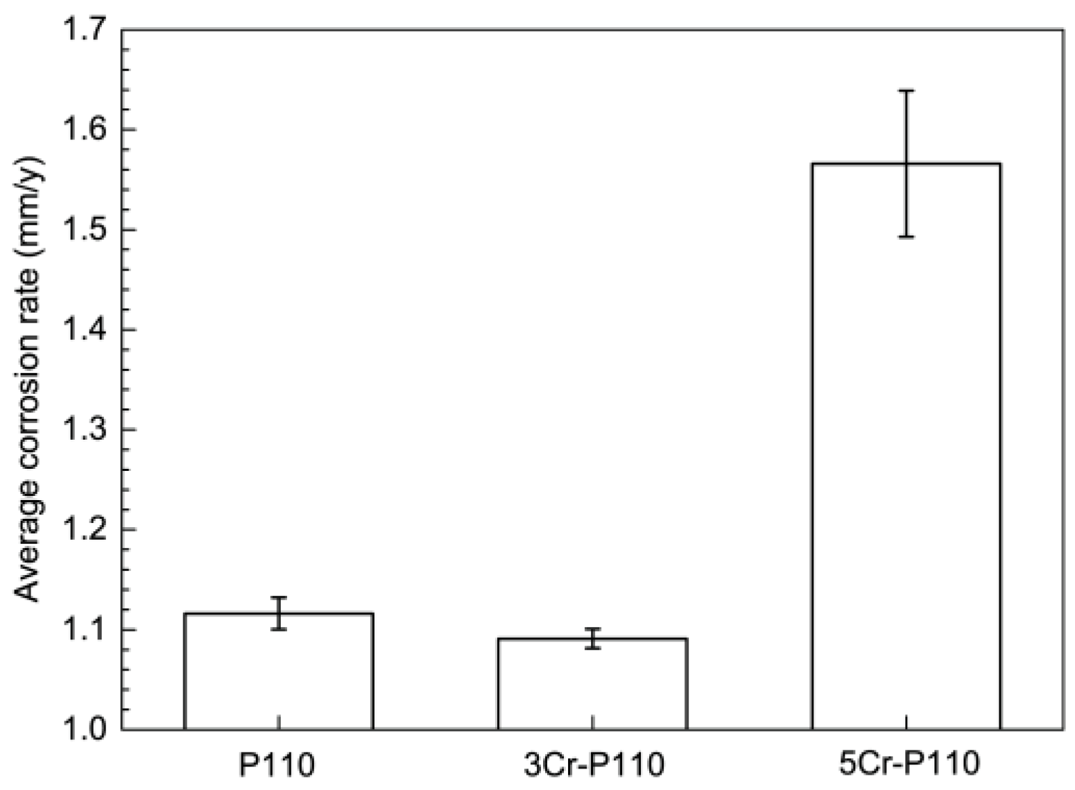
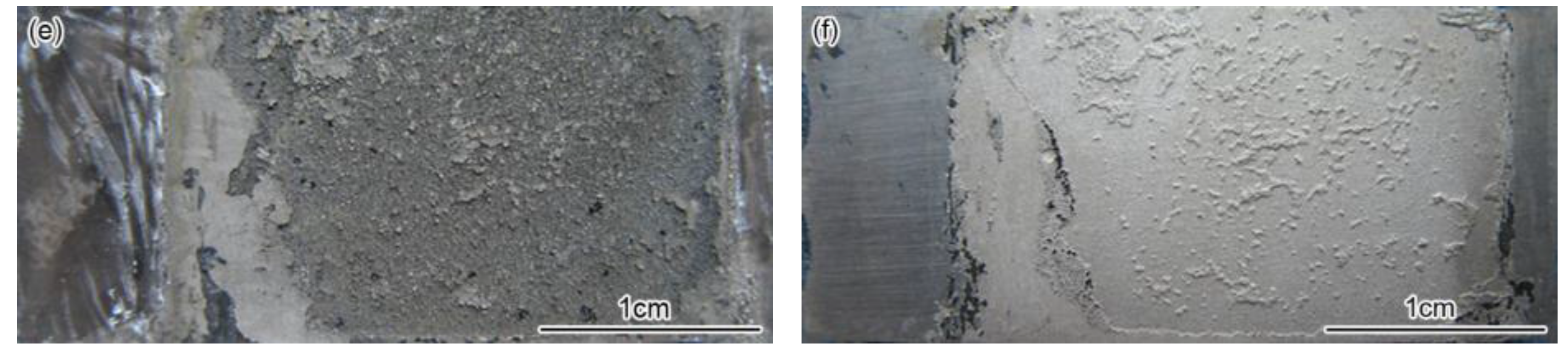
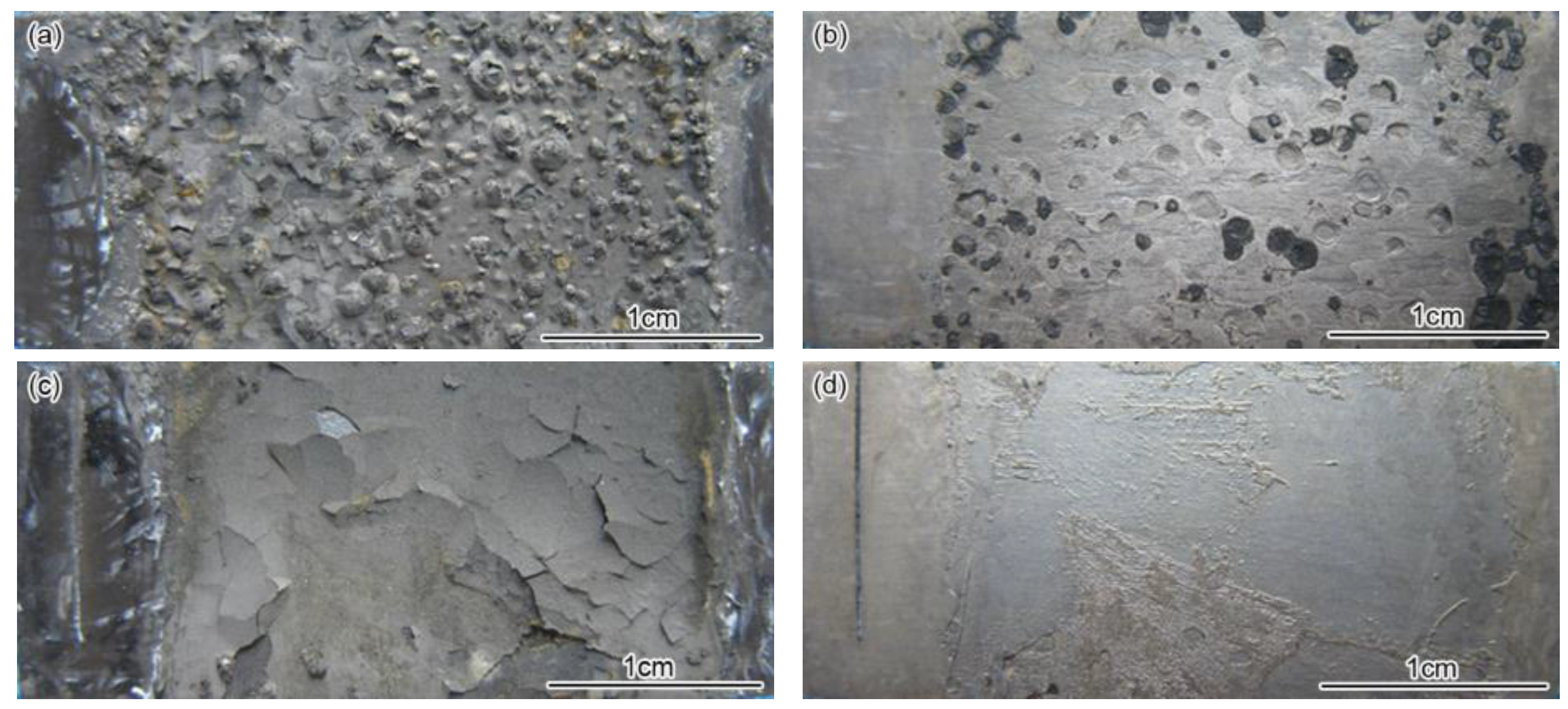
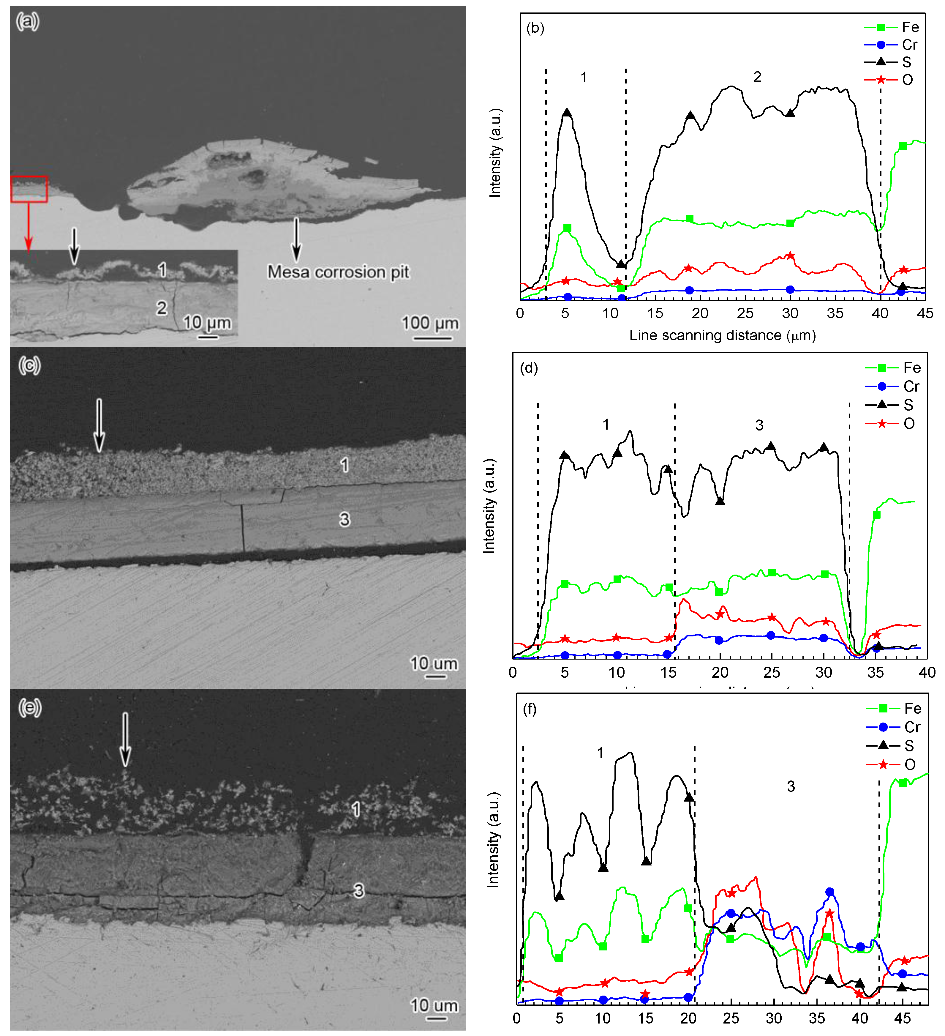
3.1. Corrosion Rate and Corrosion Form

Figure 1 presents the average corrosion rates of tested tube steels after immersion corrosion tests in a CO2-H2S environment. It can be seen that the corrosion rate of 5Cr-P110 (1.57 mm/y) was the highest among the three steels, and the corrosion rate of 3Cr-P110 (1.08 mm/y) was approximate to that of P110 (1.12 mm/y), taking into account the experimental error. This suggests that the corrosion resistance of P110 tube steel cannot be significantly improved by increasing Cr content in a CO2-H2S condition (PCO2 = 5 MPa, PH2S = 0.2 MPa). Therefore, although the low-chromium steel has exhibited eminent corrosion resistance in CO2 environment, especially when Cr content is 3–5 wt % in the steel [11,12], it may not be necessarily applicable to the CO2-H2S condition with high pressure. That is to say, for low Cr steel, the corrosion performance varies depending on different operational conditions. In a CO2 environment, the protection is provided through the formation of a Cr-enriched FeCO3 corrosion product (Cr oxi-hydroxide) [9,10,11,12,13]. The more chromium the steel contains, the more chromium compounds the corrosion products contain, and the better the protection is. However, under test condition, H2S might play a significant role in determining the type and properties of the corrosion scales, i.e., gradually undermining the corrosion scales and reducing their protective performance [1,14].
Figure 2 shows the macroscopic surface morphology of the three steels before and after the removal of corrosion scales. As exhibited in the figures, the P110 steel surface were covered with tumor-like corrosion products (Figure 2a), and after removal of the corrosion scales, the positions where the “tuberculation” covered suffered shallow mesa attack (Figure 2b). This indicates that there is probably some connection between localized corrosion and the corrosion scale at that location. In contrast, the corrosion scales were relatively flat on 3Cr-P110 and 5Cr-P110 steels surface with a non-adhesive outer layer (Figure 2c,e). After the specimens were taken out from solution, the outer layer cracked due to dehydration and partly peeled-off the 3Cr-P110 steel surface (Figure 2c), and most of the outer layer scales peeled off the 5Cr-P110 steel surface (Figure 2e). 3Cr-P110 and 5Cr-P110 steels were subject to general corrosion (Figure 2d,f), indicating that the addition of 3–5 wt % Cr into carbon steel improves the localized corrosion resistance in CO2-H2S environment, which is consistent with the case in CO2 environment [11,12,13]. However, the corrosion rates of Cr-containing steels did not decrease, suggesting that the addition of chromium could increase the uniformity of the corrosion scale but not improve the diffusion resistance to corrosive ions.

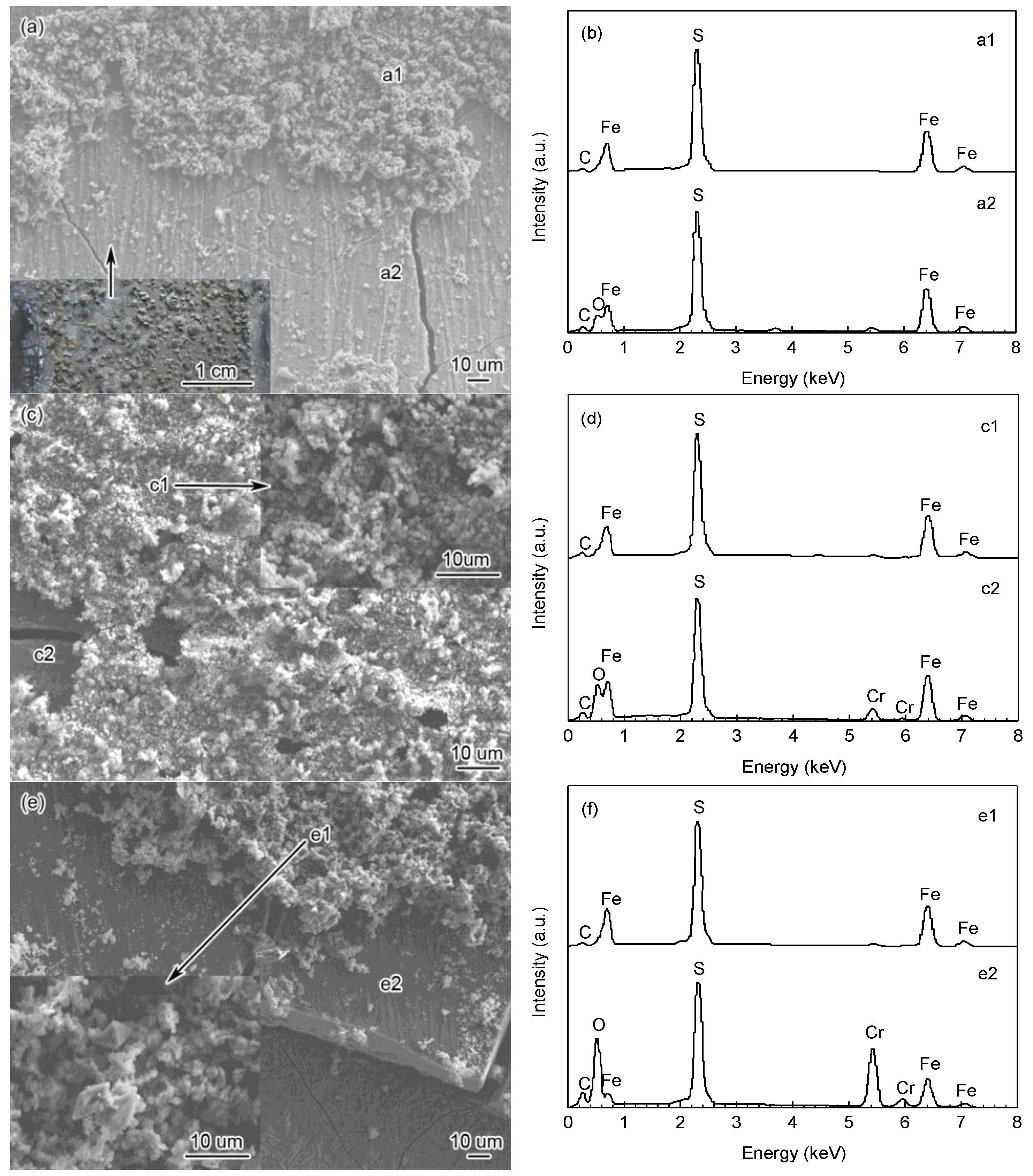
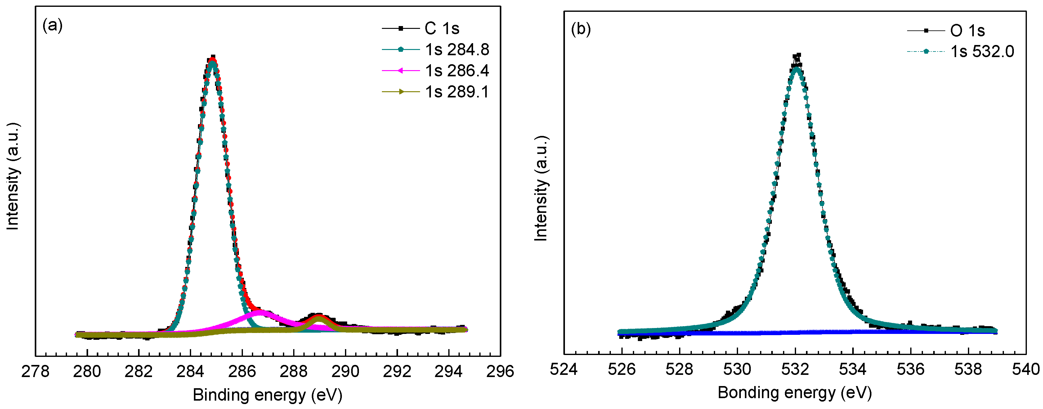
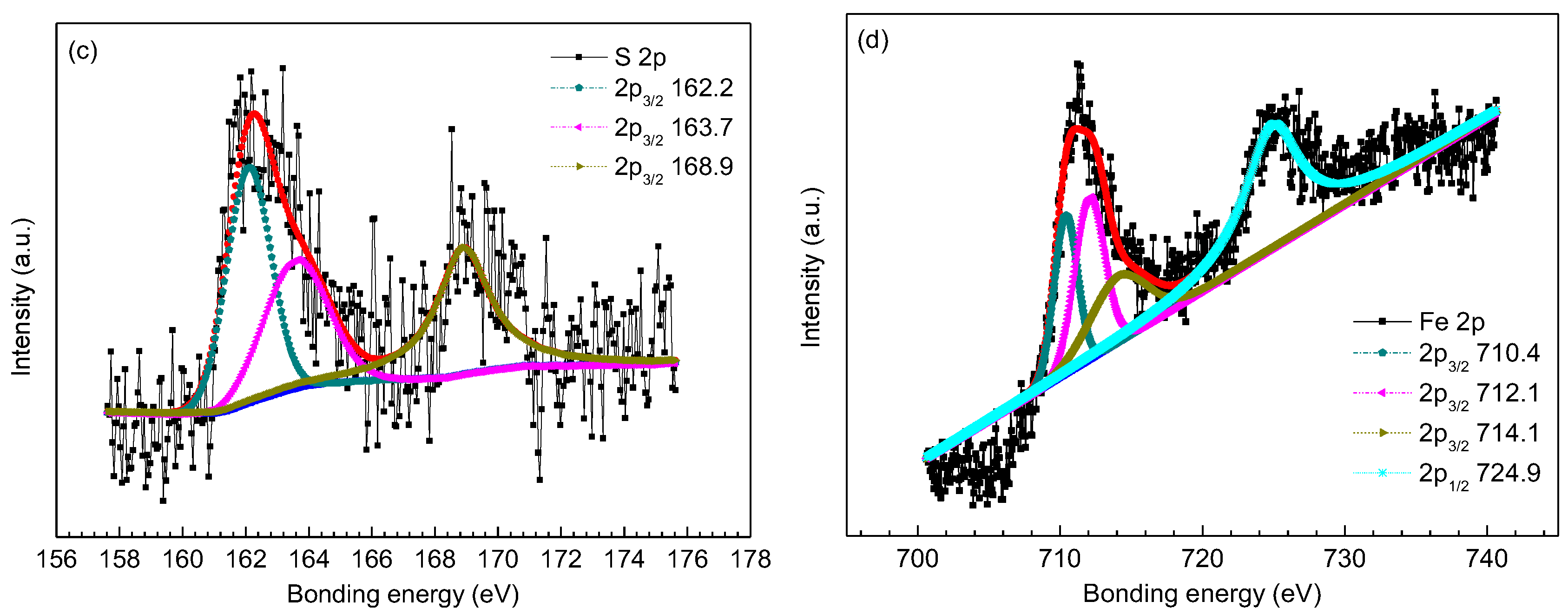
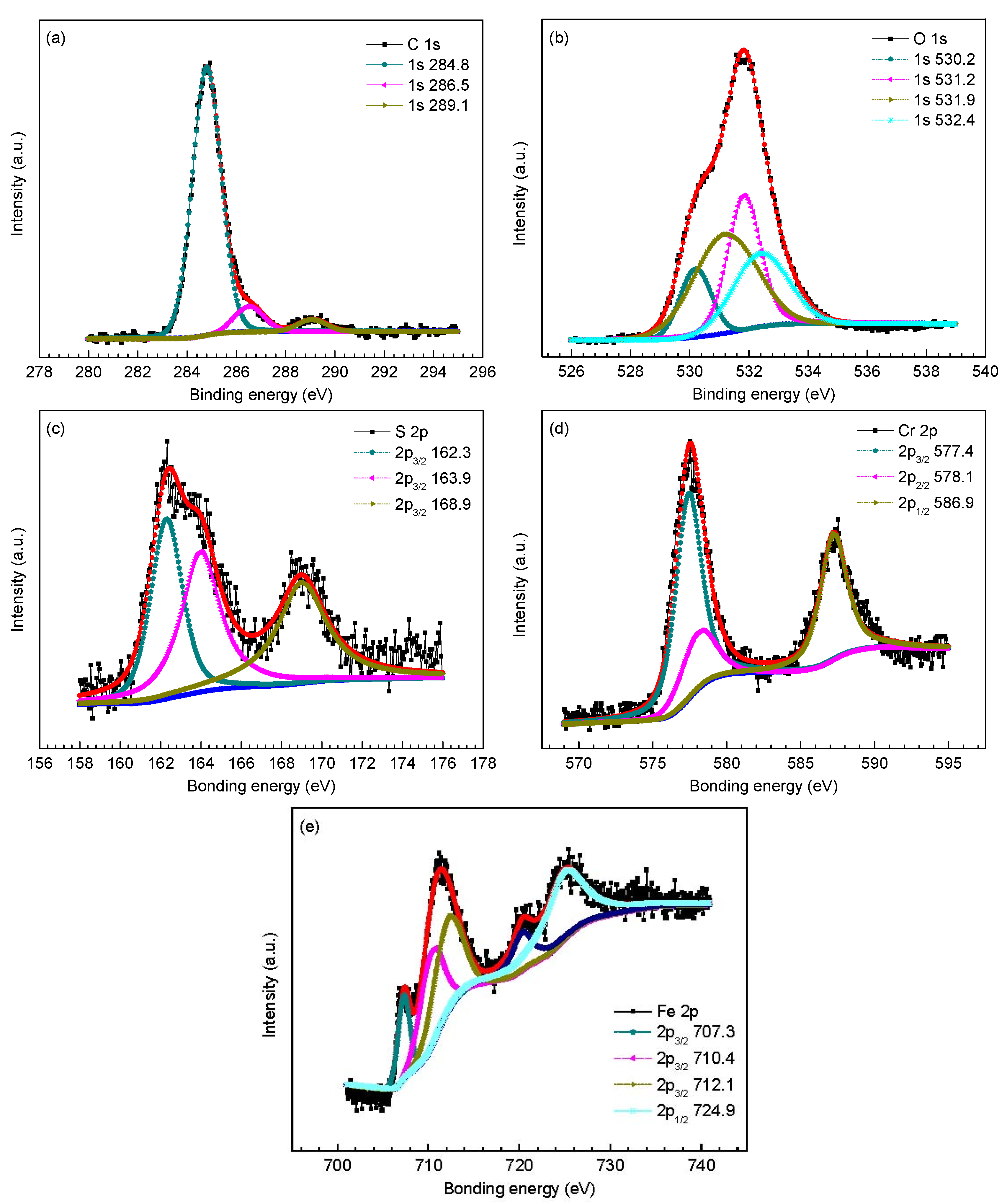
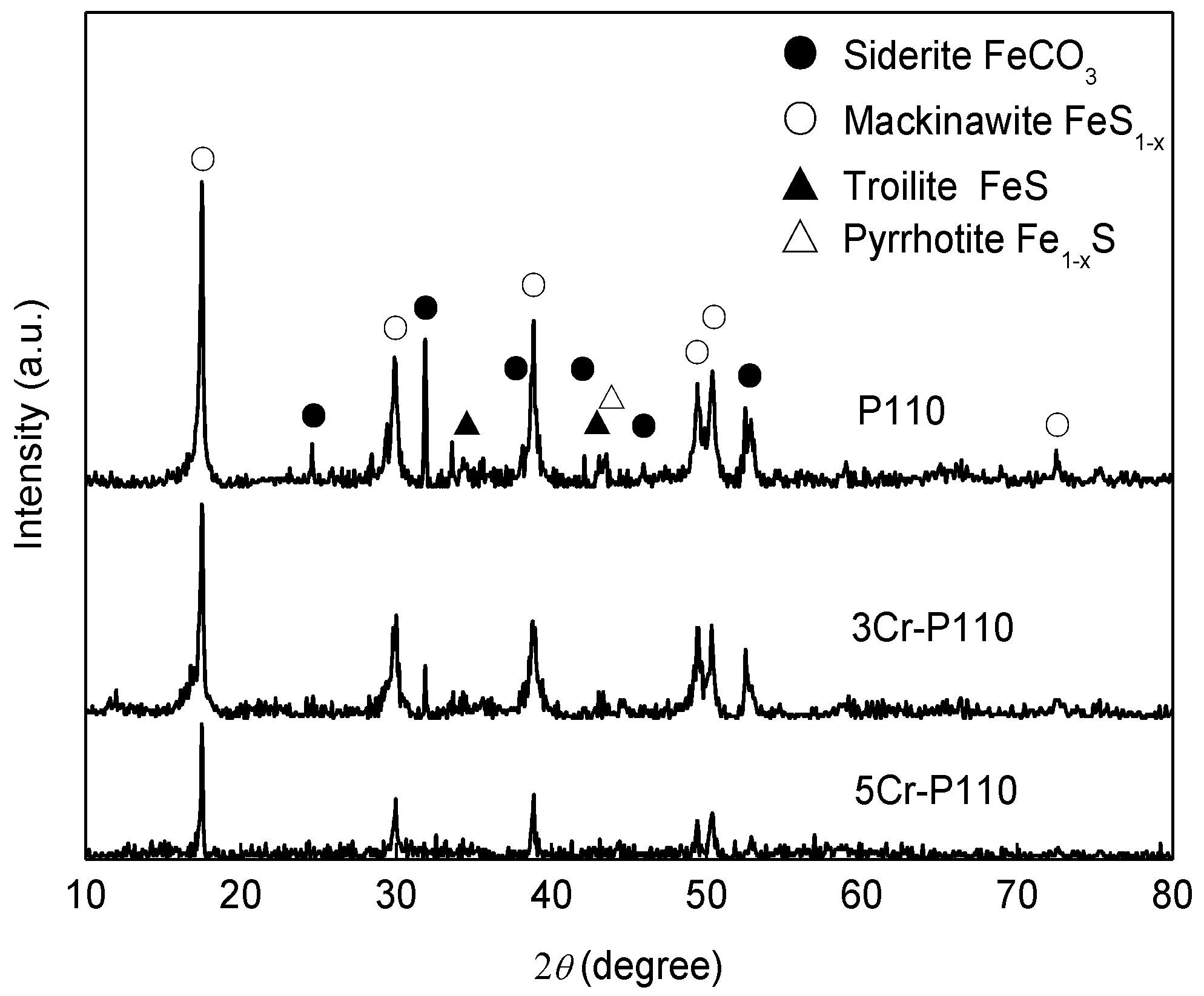
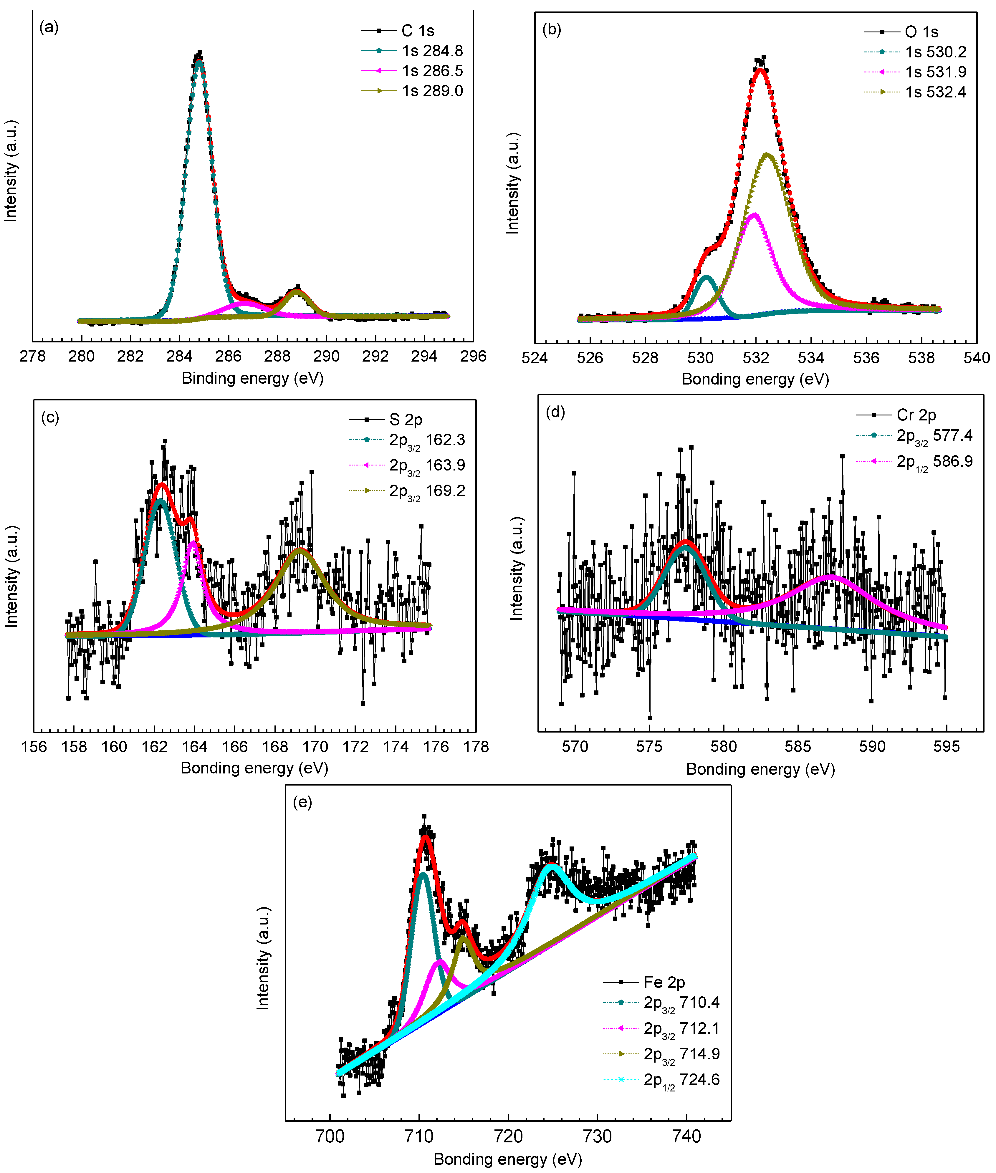
3.2. The Composition and Elements Distribution of Corrosion Film

Figure 3 shows the XRD spectra of the corrosion scales on the steels. It can be seen that the crystals in the scales of P110 steel mainly comprised FeS1−x and FeCO3, with a small amount of FeS and Fe1−x S. However the main crystals in the scales of 3Cr-P110 and 5Cr-P110 steels were FeS1−x with only a small amount of FeCO3 crystals detected. The content of FeCO3 crystals in corrosion products gradually reduced in the order of P110, 3Cr-P110 and 5Cr-P110. The crystalline state of FeCO3 is predominantly determined by the pH [9]. High pH value causes the formation of FeCO3 crystal while low pH results in amorphous FeCO3. Therefore, the reduction of FeCO3 crystals is probably, to some extent, related to the pH of the solution in the proximity of the solution/scale or solution/metal interface.
SEM surface morphology of corrosion scales on the steels are shown in Figure 4. As exhibited in Figure 4a,c,e, the corrosion scales on the three steels showed similar morphology. The outer corrosion layers comprised tiny crystalline products, and the result of EDS analysis indicated that the outer layer scales mainly consisted of Fe and S elements (Figure 4b,d,f). It was concluded that these tiny crystalline products are mainly FeS1−x. However, the inner scales showed amorphous characteristic with cracks caused by surface dehydration, and all contained Fe, S and O elements. In addition, the inner scales of 3Cr-P110 and 5Cr-P110 steels contained abundant amounts of Cr (19.99 wt % and 28.55 wt %, respectively). Therefore, there must be some compounds, such as Cr-compounds, which were undetected by XRD.
To further determine the phase composition of inner scales, XPS analysis was employed to analyze the surface chemistry of amorphous compounds in the inner scales. Figure 5, Figure 6 and Figure 7 provides the high resolution XPS spectra of inner scales on P110, 3Cr-P110 and 5Cr-P110 steels. The elements of interest were Fe, O, S and C and, in the meantime, Cr was also investigated for 3Cr-P110 and 5Cr-P110 steels. Surface charging effects were compensated by referencing the binding energy to the C 1s line of the residual carbon set at 284.6 eV. The Gaussian–Lorentzian curves were used to fit the peaks. Binding energies of Fe 2p, O 1s, S 2p, and Cr 2p for inner scales on P110, 3Cr-P110, and 5Cr-P110 samples are summarized in Table 2.
Referring to Figure 5 and Table 2 [2,27,28,29], the results suggested that the inner scale of P110 steel mainly consisted of FeS1−x and FeCO3. The S 2p3/2 peak at 163.7 eV corresponded to elemental sulfur which was detected because iron sulfide got oxidized while in air [3]. In addition, considering the limitation of the corrosion environment, the S 2p3/2 peak at a binding energy of 168.9 eV could be attributable to the adventitious SO42− [30].
The high resolution XPS spectra of inner scales on 3Cr-P110 and 5Cr-P110 steels are shown in Figure 6 and Figure 7, respectively. As exhibited in Figure 6 and Figure 7 and Table 2, the C 1s, S 2p, and Fe 2p scans for the inner scales on 3Cr-P110 and 5Cr-P110 steels reflected a similar composition of corrosion products compared to that of P110 steel, confirming the presence of FeS1-x and FeCO3. A small difference was the Fe 2p3/2 peak at 707.3 eV for 5Cr-P110 steel associated with iron sulfide [31], as shown in Figure 7e. However, a noticeable difference existed in the O spectra for 3Cr-P110 and 5Cr-P110 steels compared to that of P110 steel, along with the existence of Cr2O3 and Cr(OH)3 [9,32], except for FeCO3 [27]. The Cr 2p peaks both revealed the existence of Cr(OH)3 [9,32,33] in 3Cr-P110 and 5Cr-P110 scales. The Cr2O3 [32] in 5Cr-P110 scale was believed to be the product of the dehydration of Cr(OH)3 upon removal from the system [13]. The compositions of the inner scale on 3Cr-P110 and 5Cr-P110 steels were similar, both primarily consisting of FeS1−x, FeCO3 and amorphous Cr(OH)3.
Figure 8 shows the cross-sectional backscattered electron images and EDS line scanning analysis of corrosion scales on the steels. As exhibited in Figure 8a,c,e, the scales on P110 (the position where P110 steel presented general corrosion morphology), 3Cr-P110 and 5Cr-P110 steels all had a two-layer structure after 360 h corrosion tests. It can be seen that the outer scales on three steels (Figure 8a–f) mainly contained Fe and S elements (FeS1−x), the inner scale on P110 steel (Figure 8a,b) mainly contained Fe, S, and O elements (FeS1−x and FeCO3) and the inner scale on 3Cr-P110 (Figure 8c,d) and 5Cr-P110 (Figure 8e,f) steels mainly contained Fe, Cr, S and O elements (FeS1−x, Cr(OH)3, and FeCO3). The results were highly consistent with XRD and XPS analysis. As exhibited in Figure 8a, the outer FeS1−x scale of P110 steel was very thin, uneven, and not closely attached to the inner scale with many large pores between inner and outer scales compared with that of 3Cr-P110 steel (Figure 8c). Whereas, for 5Cr-P110 steel, the outer FeS1−x scale was porous and loose (Figure 8e) compared with that of 3Cr-P110 steel. This is the reason why most of the outer scale of 5Cr-P110 steel peeled off (Figure 2e).
According to the characteristics of corrosion scales on the tested steels, it is reasonable to believe that the corrosion process of the steels is simultaneously governed by CO2 and H2S under the test conditions (PCO2/PH2S = 25, 90 °C). It is well established that corrosion scales containing the same components could be extremely protective, very little so, or even corrosive depending on the location of these components [9,12,34,35,36,37]. The uneven formation and local damage of CO2 corrosion product film is the main reason for localized corrosion [38]. The mesa corrosion was observed from Figure 2b and Figure 8a, and the outer FeS1−x scale disappeared in the regions where localized corrosion occurred. The local damage of corrosion scales on P110 steel provides the pathway for mass transfer of corrosive ions such as Cl, HCO3, HS, and H+, which are sufficient to cause the onset of internal acidification [34], thus accelerating the dissolution of metal at the location. As the corrosion proceeds, a mass of corrosion products is formed in corrosion pits, thus forming the tumor-like corrosion products on the steel (Figure 2a and Figure 8a). However, for the Cr-containing steel, the formation of uniform corrosion scales inhibits the localized corrosion, which may be related to the high Cr content in corrosion films.

3.3. The Effect of Cr Content on Formation of Corrosion Scale and Its Relation to Corrosion

It is well established that driving force for precipitation is the supersaturation of corrosion products in CO2-H2S environment, which depends on both the carbon steel characteristics (microstructure, heat treatment history, alloying elements) and environmental variables (solution pH, temperature, solution composition, flow rate, etc.) [1,35]. As mentioned earlier, FeCO3, FeySx and Cr(OH)3 were all detected in the corrosion scales. The competitive deposition of FeCO3, FeySx, and Cr(OH)3 results in the mixed films which play an important role in determining the corrosion form and corrosion rate.
In this study, H2S can increase CO2 corrosion by promoting anodic dissolution through sulfide adsorption and lowering pH and chromium can provide additional anodic reaction for Cr-containing steels. Therefore, both P110 steel and Cr-containing steels can be corroded rapidly at the early stage of the immersion period. Then, the supersaturation is so high that a high nucleation rate may emerge, causing an amorphous corrosion film formation on the steel surface. It can be seen from the cross-sections (Figure 8) that all the inner layers attached directly to the steel surface were apparently denser than outer layers, indicating a better protective performance of inner layers than outer layers. The inner scales acted as a diffusion barrier restricting the diffusion of reactive species and lowering the corrosion rates with time. It can also be seen that the inner layer on 5Cr-P110 was obviously not as compact as those on P110 and 3Cr-P110, which goes against the results in sweet system [12]. It suggested [14] that FeySx interfered with FeCO3 and Cr(OH)3 mixed film and reduced its protective properties especially for 5Cr-P110. Therefore, 5Cr-P110 had the highest corrosion rate, which may be attributable to the excessive chromium in 5Cr-P110 steel. According to the EDS line scanning analysis along the vertical direction of the cross-section (Figure 8b,d,f), the Cr content increased and S content decreased obviously in the inner scale on 5Cr-P110 steel compared with those in the inner scales on P110 and 3Cr-P110 steels. Since Cr(OH)3 is more stable than FeCO3 and FeySx, thermodynamically, the enrichment of Cr in the amorphous inner layers is due to the dissolution of FeCO3 [13,39] and FeySx in the scale, but it is unclear how H2S interferes with the Cr-enriched corrosion film formation and, hence, relatively lowers the protection properties of the films.
At the later stage of the immersion period, the outer FeS1−x layer with a small crystalline form precipitated on the inner layers. However, the outer FeS1−x scales of the three steels are strikingly different, such as the thickness and compactness, probably because of the the amorphous Cr(OH)3 in the inner scales. Guo et al. [9] found that the Cr content in steel had a significant impact on the in situ pH value of solution in the proximity of the scale/solution interface. The pH value can be reduced due to the formation of Cr(OH)3 by Equation (2) [9] or to the hydrolysis of Cr3+ ions by Equation (3) [40]. The higher the Cr content is, the lower the pH value can be achieved at the solution/scale interface. Therefore, the pH value in the proximity of 5Cr-P110 steel is lower than that of 3Cr-P110 steel, which results in a lower precipitation rate and higher dissolution rate of the film on 5Cr-P110 steel, and a porous, loosely-adherent FeS1−x scale formation on the inner layer (Figure 8c). Additionally, the lower pH value in the proximity of Cr-containing steels may also, to some extent, be responsible for the lower content of FeCO3 crystals in corrosion products (Figure 3). In low Cr steels, the protection is afforded through the formation of a Cr-rich FeCO3 corrosion product (Cr oxi-hydroxide) in sweet production conditions [8,9,10,11,12,13]. On the introduction of H2S (sour systems), the formation of FeS1−x may interfere with Cr-enriched corrosion scales and make the diffusion fluxes of the species involved in the electrochemical reactions easier, lowering the corrosion performance of Cr-containing steels, especially 5Cr-P110 steel. Therefore, 5Cr-P110 steel presents a higher corrosion rate.
Cr3+ + H2O → Cr(OH)3 + 3H+
[Cr(H2O)6]3+ + H2O → [Cr(H2O)5OH]2+ + H3O+

4. Conclusions

P110 steel suffered localized corrosion and both 3Cr-P110 and 5Cr-P110 steels exhibited general corrosion in CO2-H2S environment with high pressure and high temperature. The corrosion rate of 3Cr-P110 (1.08 mm/y) was approximate to that of P110 (1.12 mm/y) and the corrosion rate of 5Cr-P110 (1.57 mm/y) was the highest among the three steels.
The corrosion process of the steels was governed by CO2 and H2S simultaneously under the test conditions. The outer scales on the three steels mainly consisted of FeS1−x crystals. The inner scale on P110 steel was composed of amorphous FeS1−x and FeCO3. However, the inner scale on both 3Cr-P110 and 5Cr-P110 steels comprised amorphous FeS1−x, Cr(OH)3, and FeCO3. The inner layers attached directly to the steel surface were apparently denser than outer layers. The more chromium the steel contains, the more chromium compounds the corrosion products contain. The addition of chromium in steels increases the uniformity of the Cr-enriched corrosion scales, eliminates the localized corrosion, but cannot decrease the general corrosion rates. Under test condition, the formation of FeS1−x may interfere with Cr-enriched corrosion scales and reduce their protective properties.
However, it is still unclear how H2S interferes with the Cr-enriched corrosion film formation. As a consequence of the complexity of CO2/H2S corrosion, there is a need to carry out further study in order to clarify the mechanism involved in the chromium effect on the corrosion behavior and to develop novel low-chromium steels of both good CO2/H2S corrosion resistance and low cost.

Acknowledgments

This work was supported by National Natural Science Foundation of China (No. 51471188) and Natural Science Foundation of Shandong Province (No. ZR2014EMM002).

Author Contributions

Jianbo Sun conceived and designed the experiments; Chong Sun, Xiangkun Cheng and Huifeng Liu performed the experiments; Jianbo Sun, Chong Sun and Xueqiang Lin analyzed the data; Jianbo Sun and Chong Sun wrote the paper.

Conflicts of Interest

The authors declare no conflict of interest.

References

  1. Kermani, M.B.; Morshed, A. Carbon dioxide corrosion in oil and gas production—A compendium. Corrosion 2003, 59, 659–683. [Google Scholar] [CrossRef]
  2. Choi, Y.S.; Nesic, S.; Ling, S. Effect of H2S on the CO2 corrosion of carbon steel in acidic solutions. Electrochim. Acta 2011, 56, 1752–1760. [Google Scholar] [CrossRef]
  3. Sun, W.; Nesic, S.; Papavinasam, S. Kinetics of corrosion layer formation. Part 2—Iron sulfide and mixed iron sulfide/carbonate layers in carbon dioxide/hydrogen sulfide corrosion. Corrosion 2008, 64, 586–599. [Google Scholar] [CrossRef]
  4. López, D.A.; Pérez, T.; Simison, S.N. The influence of microstructure and chemical composition of carbon and low alloy steels in CO2 corrosion. Mater. Des. 2003, 24, 561–575. [Google Scholar] [CrossRef]
  5. Kermani, M.B.; Gonzales, J.C.; Turconi, G.L.; Edmonds, D.; Dicken, G.; Scoppio, L. Development of superior corrosion resistance 3% Cr steels for downhole applications. In CORROSION 2003; NACE International: Houston, TA, USA, 2003. [Google Scholar]
  6. Wu, Q.L.; Zhang, Z.H.; Dong, X.M.; Yang, J.Q. Corrosion behavior of low-alloy steel containing 1% chromium in CO2 environments. Corros. Sci. 2013, 75, 400–408. [Google Scholar] [CrossRef]
  7. Kermani, M.B.; Gonzales, J.C.; Linne, C.; Dougan, M.; Cochrane, R. Development of low carbon Cr-Mo steels with exceptional corrosion resistance for oilfield applications. In CORROSION 2001; NACE International: Houston, TA, USA, 2001. [Google Scholar]
  8. Kermani, M.B.; Gonzales, J.C.; Turconi, G.L.; Perez, T.; Morales, C. In-field corrosion performance of 3% Cr steels in sweet and sour downhole production and water injection. In CORROSION 2004; NACE International: Houston, TA, USA, 2004. [Google Scholar]
  9. Guo, S.Q.; Xu, L.N.; Zhang, L.; Chang, W.; Lu, M.X. Corrosion of alloy steels containing 2% chromium in CO2 environments. Corros. Sci. 2012, 63, 246–258. [Google Scholar] [CrossRef]
  10. Ueda, M. Effect of alloying elements and microstructure on stability of corrosion product in CO2 and/or H2S environments. Chem. Eng. Oil Gas 2005, 34, 43–52. (In Chinese) [Google Scholar]
  11. Takabe, H.; Ueda, M. The formation behavior of corrosion protective films of low Cr bearing steels in CO2 environments. In CORROSION 2001; NACE International: Houston, TA, USA, 2001. [Google Scholar]
  12. Sun, J.B.; Liu, W.; Chang, W.; Zhang, Z.H.; Li, Z.T.; Yu, T.; Lu, M.X. Characteristics and formation mechanism of corrosion scales on low-chromium X65 steels in CO2 environment. Acta Metall Sin 2009, 45, 84–90. (In Chinese) [Google Scholar]
  13. Chen, C.F.; Lu, M.X.; Sun, D.B.; Zhang, Z.H.; Chang, W. Effect of chromium on the pitting resistance of oil tube steel in a carbon dioxide corrosion system. Corrosion 2005, 61, 594–601. [Google Scholar] [CrossRef]
  14. Pigliacampo, L.; Gonzales, J.C.; Turconi, G.L.; Perez, T.; Morales, C.; Kermani, M.B. Window of application and operational track record of low carbon 3Cr steel tubular. In CORROSION 2006; NACE International: Houston, TA, USA, 2006. [Google Scholar]
  15. Perdomo, J.J.; Morales, J.L.; Viloria, A.; Lusinchi, A.J. CO2 and H2S corrosion of API 5L-B and 5L-X52 grade steels. In CORROSION 2000; NACE International: Houston, TA, USA, 2000. [Google Scholar]
  16. Omar, I.H.; Gunaltun, Y.M.; Kvarekval, J.; Dugstad, A. H2S corrosion of carbon steel under simulated kashagan field conditions. In CORROSION 2005; NACE International: Houston, TA, USA, 2005. [Google Scholar]
  17. Sun, W.; Nesic, S. A mechanistic model of uniform hydrogen sulfide/carbon dioxide corrosion of mild steel. Corrosion 2009, 65, 291–307. [Google Scholar] [CrossRef]
  18. Abayarathna, D.; Naraghi, A.; Obeyesekere, N. Inhibition of corrosion of carbon steel in the presence of CO2, H2S and S. In CORROSION 2003; NACE International: Houston, TA, USA, 2003. [Google Scholar]
  19. Smith, S.N.; Joosten, M.W. Corrosion of carbon steel by H2S in CO2 containing oilfield environments. In CORROSION 2006; NACE International: Houston, TA, USA, 2006. [Google Scholar]
  20. Sun, W.; Nesic, S. A mechanistic model of H2S corrosion of mild steel. In CORROSION 2007; NACE International: Houston, TA, USA, 2007. [Google Scholar]
  21. Valdes, A.; Case, R.; Ramirez, M.; Ruiz, A. The effect of small amounts of H2S on CO2 corrosion of a carbon steel. In CORROSION 98; NACE International: Houston, TA, USA, 1998. [Google Scholar]
  22. Ren, C.Q.; Liu, D.X.; Bai, Z.Q.; Li, T.H. Corrosion behavior of oil tube steel in simulant solution with hydrogen sulfide and carbon dioxide. Mater. Chem. Phys. 2005, 93, 305–309. [Google Scholar] [CrossRef]
  23. Li, D.P.; Zhang, L.; Yang, J.W.; Lu, M.X.; Ding, J.H.; Liu, M.L. Effect of H2S concentration on the corrosion behavior of pipeline steel under the coexistence of H2S and CO2. Int. J. Min. Met. Mater. 2014, 21, 388–394. [Google Scholar] [CrossRef]
  24. Kvarekval, J.; Nyborg, R.; Seiersten, M. Corrosion product films on carbon steel in semi-sour CO2/H2S environments. In CORROSION 2002; NACE International: Houston, TA, USA, 2002. [Google Scholar]
  25. Pots, B.F.M.; John, R.C.; Rippon, I.J.; Thomas, M.J.J.S.; Kapusta, S.D.; Girgis, M.M.; Whitham, T. Improvements on de waard-milliams corrosion prediction and applications to corrosion management. In CORROSION 2002; NACE International: Houston, TA, USA, 2002. [Google Scholar]
  26. Srinivasan, S.; Kane, R.D. Prediction of corrosivity of CO2/H2S production environments. In CORROSION 96; NACE International: Houston, USA, 1996. [Google Scholar]
  27. Heuer, J.K.; Stubbins, J.F. An XPS characterization of FeCO3 films from CO2 corrosion. Corros. Sci. 1999, 41, 1231–1243. [Google Scholar] [CrossRef]
  28. Lopez, D.A.; Schreiner, W.H.; de Sanchez, S.R.; Simison, S.N. The influence of inhibitors molecular structure and steel microstructure on corrosion layers in CO2 corrosion. Appl. Surf. Sci. 2004, 236, 77–97. [Google Scholar] [CrossRef]
  29. Lee, K.L.J.; Nesic, S. The effect of trace amount of H2S on CO2 corrosion investigated by using the EIS technique. In CORROSION 2005; NACE International: Houston, TA, USA, 2005. [Google Scholar]
  30. Xiang, Y.; Wang, Z.; Xu, C.; Zhou, C.C.; Li, Z.; Ni, W.D. Impact of SO2 concentration on the corrosion rate of X70 steel and iron in water-saturated supercritical CO2 mixed with SO2. J. Supercrit. Fluids 2011, 58, 286–294. [Google Scholar] [CrossRef]
  31. Mullet, M.; Boursiquot, S.; Abdelmoula, M.; Genin, J.M.; Ehrhardt, J.J. Surface chemistry and structural properties of mackinawite prepared by reaction of sulfide ions with metallic iron. Geochim. Cosmochim. Acta 2002, 66, 829–836. [Google Scholar] [CrossRef]
  32. Desimoni, E.; Malitesia, C.; Zambonin, P.G.; Riviere, J.C. An X-ray photoelectron spectroscopic study of some chromium-oxygen systems. Surf. Interface Anal. 1988, 13, 173–179. [Google Scholar] [CrossRef]
  33. Asami, K.; Hashimoto, K. The X-ray photo-electron spectra of several oxides of iron and chromium. Corros. Sci. 1977, 17, 559–570. [Google Scholar] [CrossRef]
  34. Crolet, J.L.; Thevenot, N.; Nesic, S. The role of conductive corrosion products in the protectiveness of corrosion layers. Corrosion 1998, 54, 194–203. [Google Scholar] [CrossRef]
  35. Dugstad, A. Fundamental aspects of CO2 metal loss corrosion—Part I: Mechanism. In CORROSION 2006; NACE International: Houston, TA, USA, 2006. [Google Scholar]
  36. Schmitt, G.; Hörstemeier, M. Fundamental aspects of CO2 metal loss corrosion—Part II: Influence of different parameters on CO2 corrosion mechanisms. In CORROSION 2006; NACE International: Houston, TA, USA, 2006. [Google Scholar]
  37. Gulbrandsen, E.; Nesic, S.; Stangeland, A.; Burchardt, T.; Sundfær, B.; Hesjevik, S.M.; Skjerve, S. Effect of precorrosion on the performance of inhibitors for CO2 corrosion of carbon steel. In CORROSION 98; NACE International: Houston, TA, USA, 1998. [Google Scholar]
  38. Schmitt, G. Fundamental Aspects of CO2 Corrosion. In Advances in CO2 Corrosion; NACE International: Houston, TA, USA, 1984; pp. 10–19. [Google Scholar]
  39. Xie, Y.; Xu, L.N.; Gao, C.L.; Chang, W.; Lu, M.X. Corrosion behavior of novel 3% Cr pipeline steel in CO2 Lop-of-Line Corrosion environment. Mater. Des. 2012, 36, 54–57. [Google Scholar] [CrossRef]
  40. Chen, T.H.; Xu, L.N.; Lu, M.X.; Chang, W.; Zhang, L. Study on factors affecting low Cr alloy steels in a CO2 corrosion. In CORROSION 2011; NACE International: Houston, TA, USA, 2011. [Google Scholar]
Figure 1. Average corrosion rates of P110, 3Cr-P110 and 5Cr-P110 tube steels in 3.5 wt % NaCl solution with CO2 and H2S (PCO2 = 5 MPa, PH2S = 0.2 MPa, 90 °C, 1 m/s, 360 h). The error bar of average corrosion rate was calculated from the three parallel specimens for each test.
Materials 09 00200 g001
Figure 2. Macroscopic surface morphology of the tube steels before (a,c,e) and after (b,d,f) the removal of corrosion scales (PCO2 = 5 MPa, PH2S = 0.2 MPa, 90 °C, 1 m/s, 360 h, 3.5 wt % NaCl): (a,b) P110; (c,d) 3Cr-P110 and (e,f) 5Cr-P110.
Materials 09 00200 g002aMaterials 09 00200 g002b
Figure 3. X-ray diffraction (XRD) spectra of corrosion scales on the steels with different Cr contents.
Materials 09 00200 g003
Figure 4. (a,c,e) Scanning electron microscope (SEM) images and (b,d,f) energy dispersive spectroscopy (EDS) analysis of the surface products on (a,b) P110; (c,d) 3Cr-P110 and (e,f) 5Cr-P110 tube steels in 3.5 wt % NaCl solution with CO2 and H2S: (b) denoted by a1 and a2 in (a); (d) denoted by c1 and c2 in (c) and (f) denoted by e1 and e2 in (e) (PCO2 = 5 MPa, PH2S = 0.2 MPa, 90 °C, 1 m/s, 360 h).
Materials 09 00200 g004
Figure 5. X-ray photoelectron spectroscopy (XPS) spectra and decomposition of peaks for different elements of the inner scale on P110 steel: (a) C 1s; (b) O 1s; (c) S 2p; and (d) Fe 2p.
Materials 09 00200 g005aMaterials 09 00200 g005b
Figure 6. X-ray photoelectron spectroscopy (XPS) spectra and decomposition of peaks for different elements of the inner scale on 3Cr-P110 steel: (a) C 1s; (b) O 1s; (c) S 2p; (d) Cr 2p; and (e) Fe 2p.
Materials 09 00200 g006
Figure 7. X-ray photoelectron spectroscopy (XPS) spectra and decomposition of peaks for different elements of the inner scale on 5Cr-P110 steel: (a) C 1s; (b) O 1s; (c) S 2p; (d) Cr 2p; and (e) Fe 2p.
Materials 09 00200 g007
Figure 8. (a,c,e) cross-sectional backscattered electron images and (b,d,f) elemental distributions in cross-sections of the corrosion scales on (a,b) P110; (c,d) 3Cr-P110, and (e,f) 5Cr-P110 tube steels: (b) denoted by arrow in (a); (d) denoted by arrow in (c) and (f) denoted by arrow in (e) (1—FeS1−x; 2—FeS1−x + FeCO3 and 3—FeS1−x + Cr(OH)3 + FeCO3).
Materials 09 00200 g008
Table 1. Chemical compositions of the tested steels (wt %).
SteelCSiCrMnMoNiPSVFe
P1100.250.290.150.760.270.0320.0090.0040.004Bal.
3Cr-P1100.260.272.990.580.190.0430.0110.0040.008Bal.
5Cr-P1100.250.235.110.540.210.0410.0080.0070.009Bal.
Table 2. Binding energies of Fe 2p, O 1s, S 2p, and Cr 2p for inner scales on P110, 3Cr-P110, and 5Cr-P110 samples exposed to 3.5 wt % NaCl solution with CO2 and H2S (PCO2 = 5 MPa, PH2S = 0.2 MPa, 90 °C, 1 m/s, 360 h). All binding energies are accurate to within ±0.2 eV or less based on three measurements per sample.
ElementP1103Cr-P1105Cr-P110
C 1s284.8 (adventitious) [28]284.8 (adventitious) [28]284.8 (adventitious) [28]
286.4 (adventitious) [28]286.5 (adventitious) [28]286.5 (adventitious) [28]
289.1 (FeCO3) [2,27]289.0 (FeCO3) [2,27]289.1 (FeCO3) [2,27]
O 1s532.0 FeCO3 [2,27,28]530.2 (Cr2O3 ) [32]530.2 (Cr2O3 ) [32]
-531.9 (FeCO3) [27]531.2 Cr(OH)3 [9]
-532.4 (Cr(OH)3) [32]531.9 (FeCO3) [27]
--532.4 (Cr(OH)3) [32]
S 2p162.2 (FeS1−x) [29]162.3 (FeS1−x) [29]162.3 (FeS1−x) [29]
163.7 (elemental sulfur) [3]163.9 (elemental sulfur) [3]163.9 (elemental sulfur) [3]
168.9 (adventitious) [30]169.2 (adventitious) [30]168.9 (adventitious) [30]
Fe 2p710.4 (FeCO3) [9,27]710.4 (FeCO3) [9,27]707.3 (iron sulfide) [31]
712.1 (FeS1−x) [29]712.1 (FeS1−x) [29]710.4 (FeCO3) [9,27]
714.1 (FeCO3) [9,27]714.9 (FeCO3) [9,27]712.1 (FeS1−x) [29]
724.9(FeCO3) [9,27]724.6(FeCO3) [9,27]724.9(FeCO3) [9,27]
Cr 2p-577.4 (Cr(OH)3) [9,32,33]577.4 (Cr(OH)3) [9,32,33]
-586.9 (Cr(OH)3) [9,32,33]578.1(Cr2O3) [32]
--586.9 (Cr(OH)3) [9,32,33]

