
Deposition of Visible Light Active Photocatalytic Bismuth Molybdate Thin Films by Reactive Magnetron Sputtering


Abstract
:1. Introduction
2. Materials and Methods
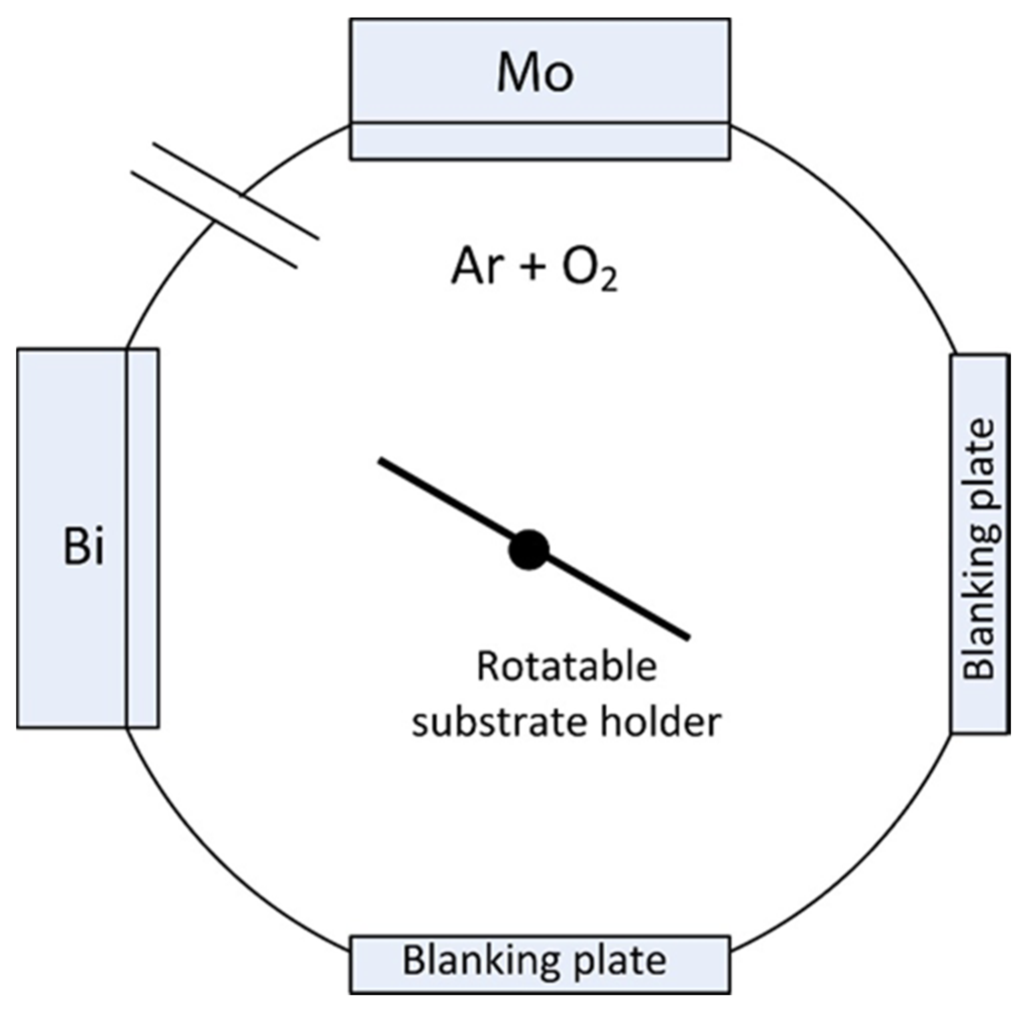
2.1. Deposition of the Coatings
2.2. Characterization of the Coatings
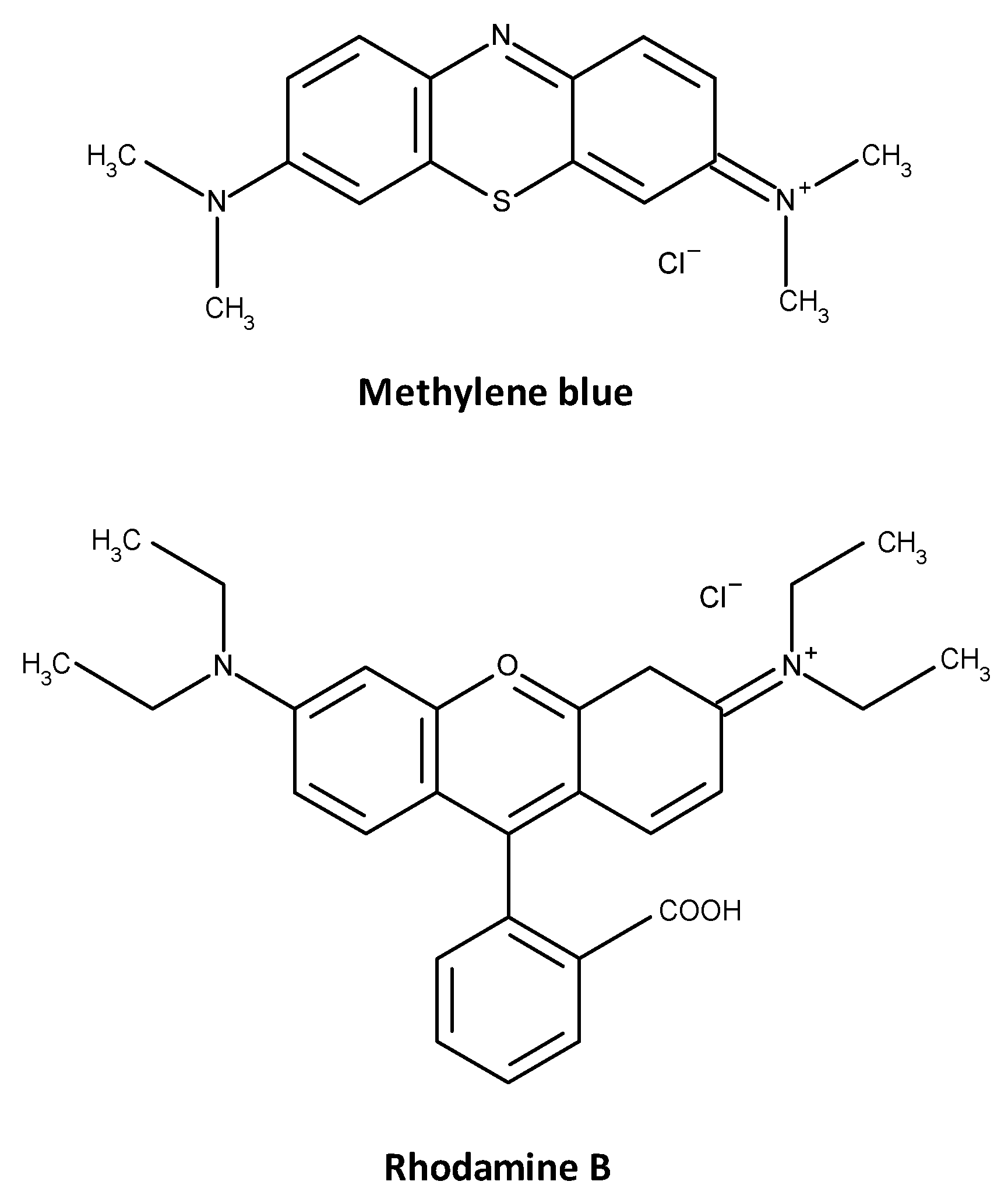
2.3. Photocatalytic Activity Assessment

3. Results and Discussion
3.1. Coatings Overview

| Sample ID | Power on Bi Target (W) | Power on Mo Target (W) | Content of Bi (at.%) | Content of Mo (at.%) | Coating Thickness (nm) | Coating Visual Appearance | Average Transmittance Value in the Visible Part of the Spectrum (%) |
|---|---|---|---|---|---|---|---|
| BMO1 | 100 | 500 | 46 | 54 | 180 | Light yellow, transparent | 79.7 |
| BMO2 | 125 | 500 | 52 | 47 | 185 | Light yellow, transparent | 80.2 |
| BMO3 | 150 | 450 | 64 | 36 | 200 | Light yellow to light brown, transparent | 74.2 |
| BMO4 | 200 | 400 | 69 | 31 | 310 | Light brown, transparent | 70.4 |
| BMO5 | 300 | 300 | 78 | 22 | 350 | Light brown, transparent | 70.1 |
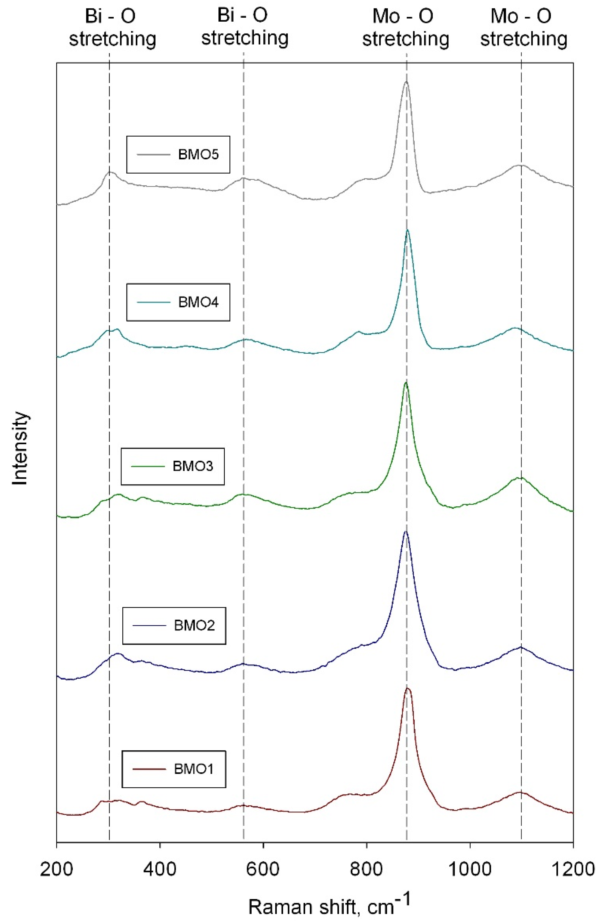
3.2. Raman Spectroscopy Results
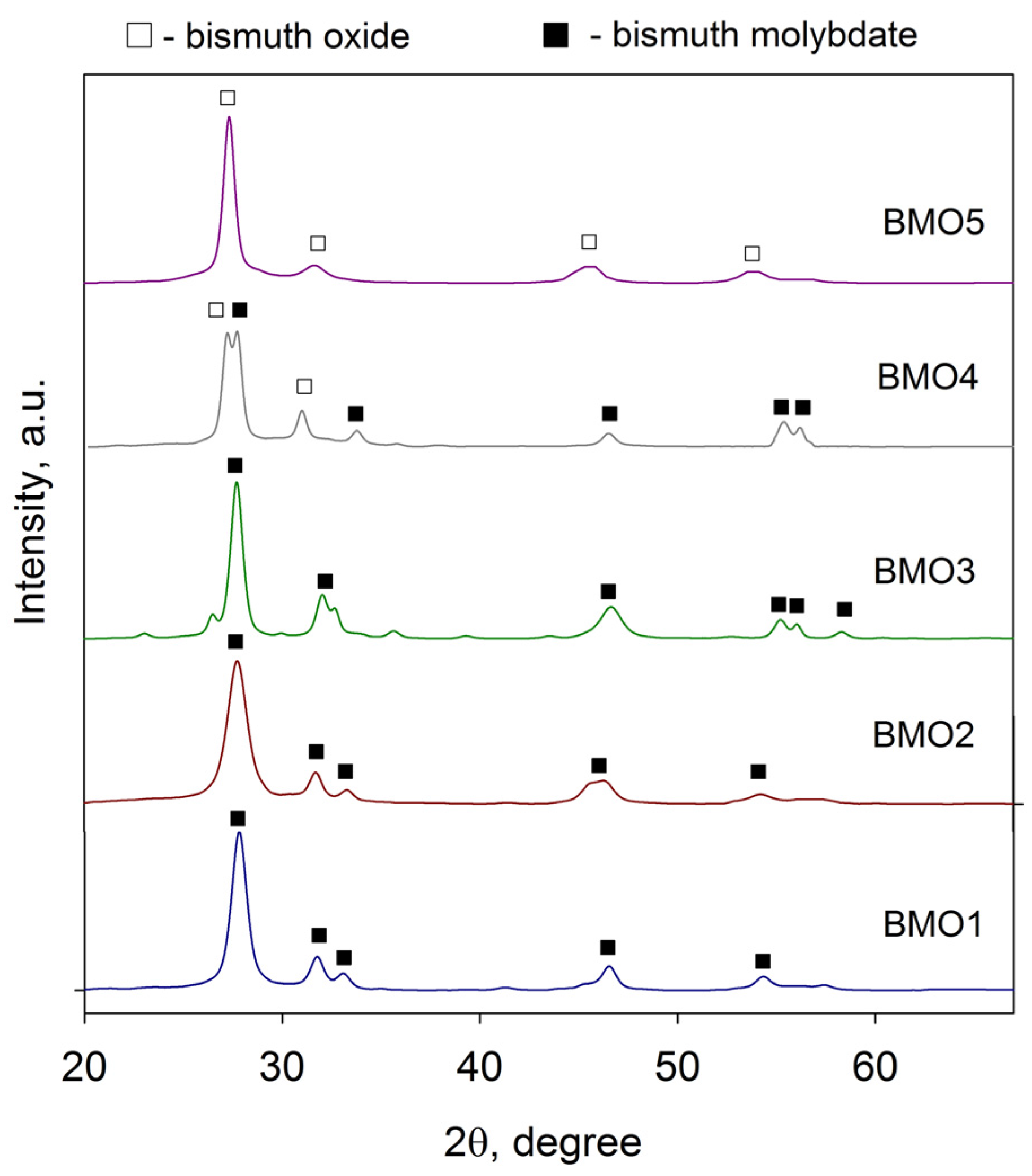
3.3. XRD Results

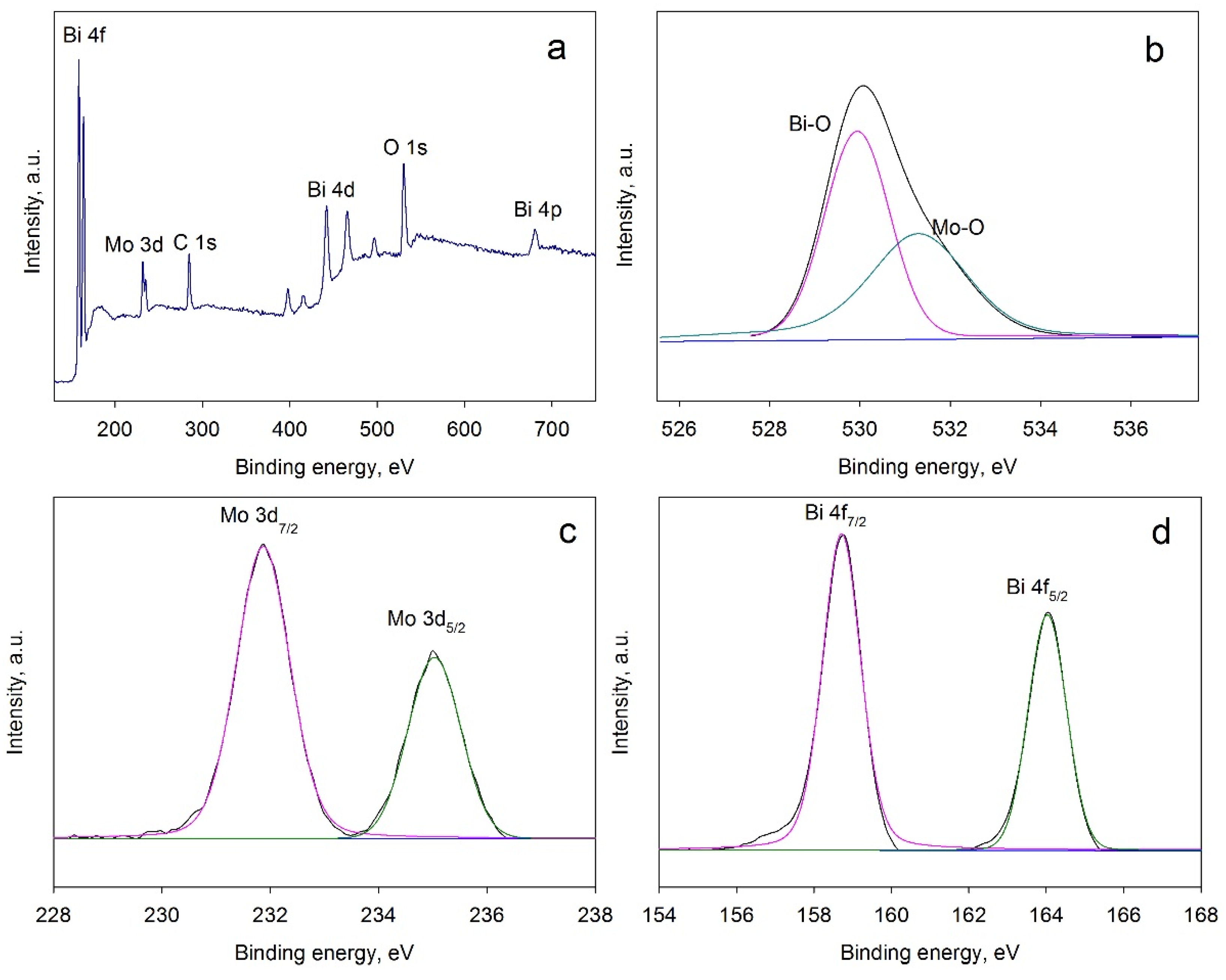
3.4. XPS Results

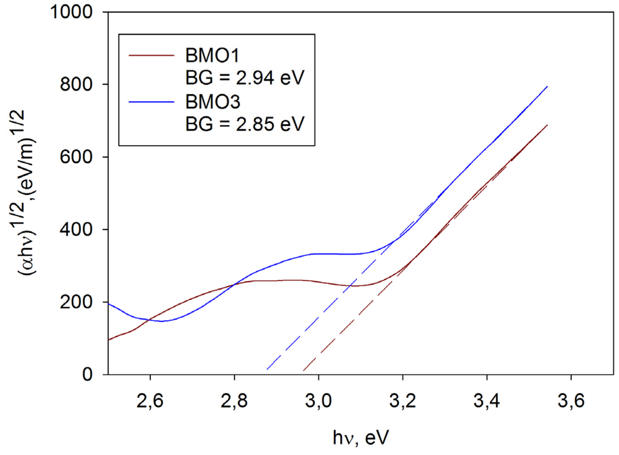
3.5. Band Gap Calculation

| Sample ID | Predominant Crystal Phase | Band Gap (eV) | Surface Roughness Sa (nm) | Methylene Blue ka × 10−5 (s−1) | Rhodamine B ka × 10−5 (s−1) |
|---|---|---|---|---|---|
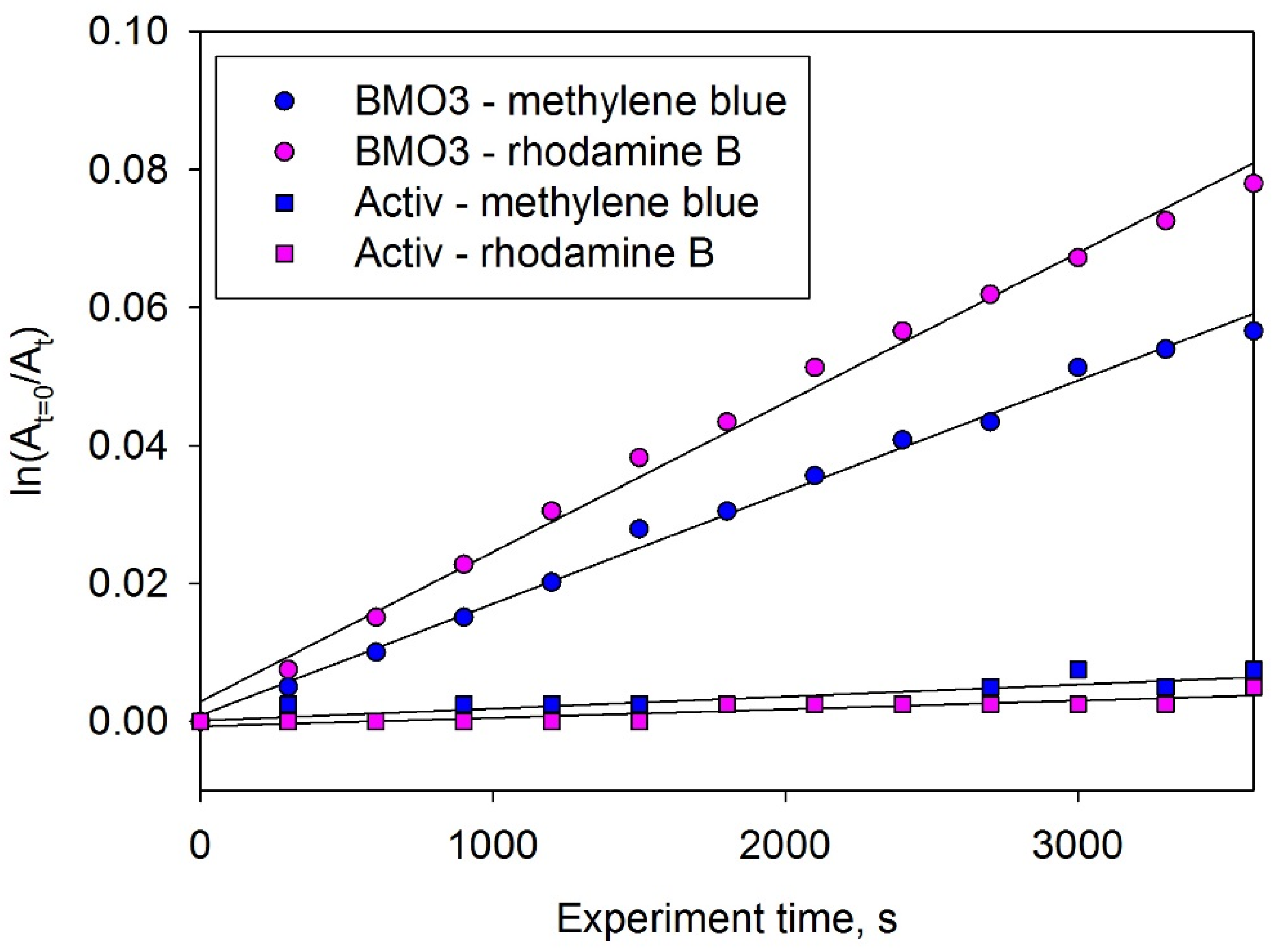
| BMO1 | Bismuth molybdate | 2.94 | 5.3 | 0.8 | 0.6 |
| BMO2 | Bismuth molybdate | 2.94 | 5.6 | 1.2 | 1.0 |
| BMO3 | Bismuth molybdate | 2.85 | 5.1 | 2.0 | 2.6 |
| BMO4 | Bismuth molybdate/bismuth oxide | 2.74 | 5.6 | 1.1 | 1.3 |
| BMO5 | Bismuth oxide | 2.65 | 5.7 | 0.4 | 0.5 |
3.6. Surface Roughness
3.7. Photocatalytic Activity

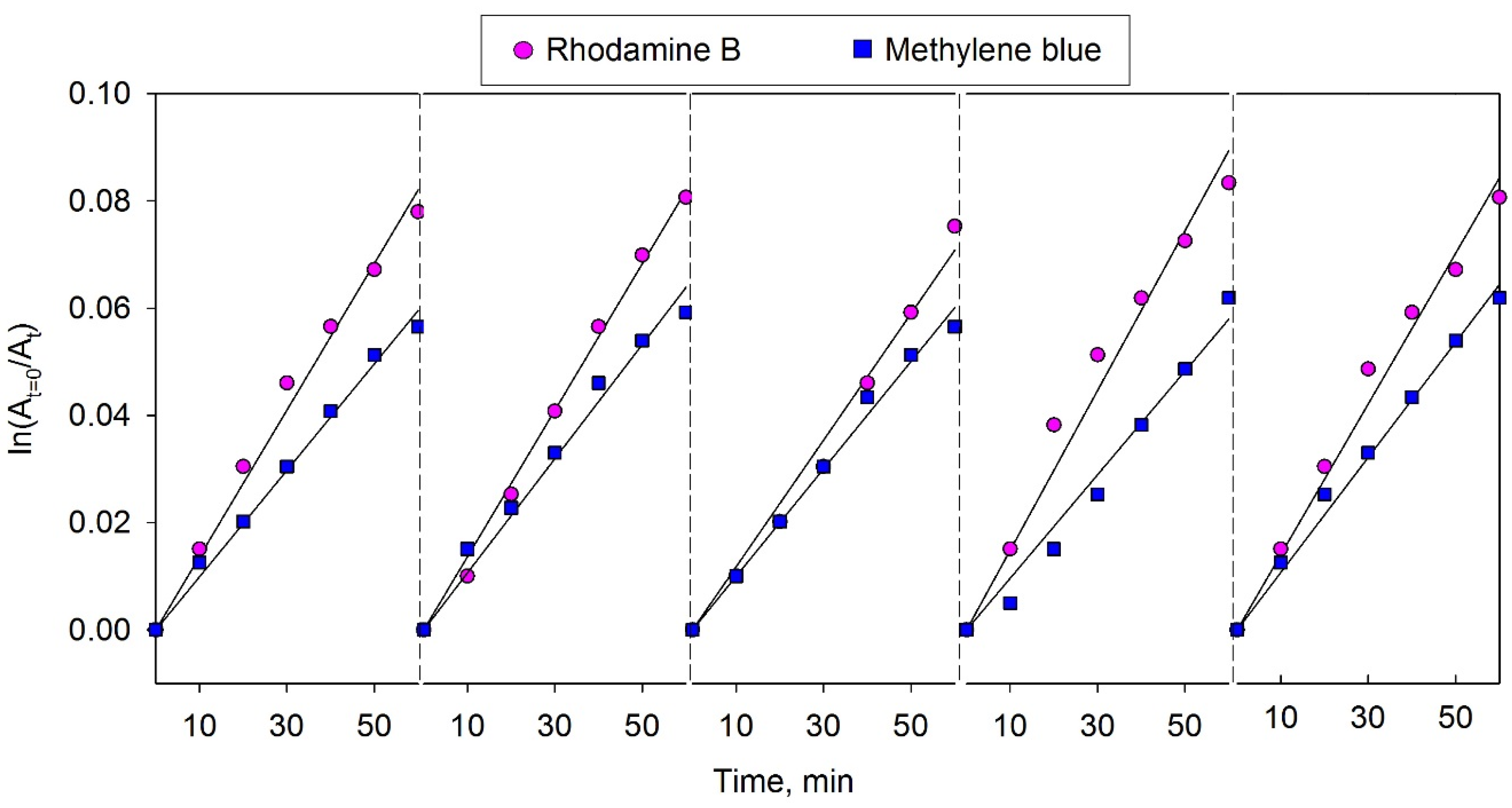
3.8. Photocatalyst Reusability Evaluation

4. Conclusions
Acknowledgments
Author Contributions
Conflicts of Interest
Abbreviations
| XRD | X-ray diffraction |
| XPS | X-ray photoelectron spectroscopy |
| SEM | scanning electron microscopy |
| EDX | energy dispersive spectroscopy |
| MB | methylene blue |
| RhB | rhodamine B |
| UV | ultraviolet |
References
- Fujishima, A.; Honda, K.; Kikuchi, S. Photosensitized electrolytic oxidation on semiconducting N-type TiO2 electrode. Kogyo Kagaku Zasshi 1969, 72, 108–113. [Google Scholar] [CrossRef]
- Paz, Y. Application of TiO2 photocatalysis for air treatment: Patents™ overview. Appl. Catal. B Environ. 2010, 99, 448–460. [Google Scholar] [CrossRef]
- Pelaez, M.; Nolan, N.T.; Pillai, S.C.; Seery, M.K.; Falaras, P.; Kontos, A.G.; Dunlop, P.S.M.; Hamilton, J.W.J.; Byrne, J.A.; O’Shea, K.; et al. A review on the visible light active titanium dioxide photocatalysts for environmental applications. Appl. Catal. B Environ. 2012, 125, 331–349. [Google Scholar] [CrossRef]
- Lu, M.; Pichat, P. Photocatalysis and Water Purification: From Fundamentals to Recent Applications; Wiley-VCH: New York, NY, USA, 2013. [Google Scholar]
- Pichat, P. Self-cleaning materials based on solar photocatalysis. In New and Future Developments in Catalysis; Suib, S.L., Ed.; Elsevier: Amsterdam, The Netherlands, 2013; Chapter 7; pp. 167–190. [Google Scholar]
- Hay, S.O.; Obee, T.; Luo, Z.; Jiang, T.; Meng, Y.; He, J.; Murphy, S.C.; Suib, S. The viability of photocatalysis for air purification. Molecules 2015, 20, 1319–1356. [Google Scholar] [CrossRef] [PubMed]
- Fujishima, A.; Zhang, X. Titanium dioxide photocatalysis: Present situation and future approaches. Comptes Rendus Chimie 2006, 9, 750–760. [Google Scholar] [CrossRef]
- Guo, C.; Xu, J.; Wang, S.; Zhang, Y.; He, Y.; Li, X. Photodegradation of sulfamethazine in an aqueous solution by a bismuth molybdate photocatalyst. Catal. Sci. Technol. 2013, 3, 1603–1611. [Google Scholar] [CrossRef]
- Hernandez-Alonso, M.D.; Fresno, F.; Suarez, S.; Coronado, J.M. Development of alternative photocatalysts to TiO2: Challenges and opportunities. Energy Environ. Sci. 2009, 2, 1231–1257. [Google Scholar] [CrossRef]
- Hykaway, N.; Sears, W.M.; Frindt, R.F.; Morrison, S.R. The gas-sensing properties of bismuth molybdate evaporated films. Sens. Actuators 1988, 15, 105–118. [Google Scholar] [CrossRef]
- Shimodaira, Y.; Kato, H.; Kobayashi, H.; Kudo, A. Photophysical properties and photocatalytic activities of bismuth molybdates under visible light irradiation. J. Phys. Chem. B 2006, 110, 17790–17797. [Google Scholar] [CrossRef] [PubMed]
- Lai, K.; Wei, W.; Zhu, Y.; Guo, M.; Dai, Y.; Huang, B. Effects of oxygen vacancy and N-doping on the electronic and photocatalytic properties of Bi2MO6 (M=Mo, W). J. Solid State Chem. 2012, 187, 103–108. [Google Scholar] [CrossRef]
- Xie, H.; Shen, D.; Wang, X.; Shen, G. Microwave hydrothermal synthesis and visible-light photocatalytic activity of γ-Bi2MoO6 nanoplates. Mater. Chem. Phys. 2008, 110, 332–336. [Google Scholar] [CrossRef]
- Zheng, Y.; Duan, F.; Wu, J.; Liu, L.; Chen, M.; Xie, Y. Enhanced photocatalytic activity of bismuth molybdates with the preferentially exposed {0 1 0} surface under visible light irradiation. J. Mol. Catal. A Chem. 2009, 303, 9–14. [Google Scholar] [CrossRef]
- Ren, J.; Wang, W.; Shang, M.; Sun, S.; Gao, E. Heterostructured bismuth molybdate composite: Preparation and improved photocatalytic activity under visible-light irradiation. ACS Appl. Mater. Interfaces 2011, 3, 2529–2533. [Google Scholar] [CrossRef] [PubMed]
- Li, H.; Li, K.; Wang, H. Hydrothermal synthesis and photocatalytic properties of bismuth molybdate materials. Mater. Chem. Phys. 2009, 116, 134–142. [Google Scholar] [CrossRef]
- Martínez-de la Cruz, A.; Gracia Lozano, L.G. Photoassisted degradation of organic dyes by β-Bi2Mo2O9. React. Kinet. Mech. Catal. 2010, 99, 209–215. [Google Scholar] [CrossRef]
- Li, H.; Liu, C.; Li, K.; Wang, H. Preparation, characterization and photocatalytic properties of nanoplate Bi2MoO6 catalysts. J. Mater. Sci. 2008, 43, 7026–7034. [Google Scholar] [CrossRef]
- Schuh, K.; Kleist, W.; Hoj, M.; Trouillet, V.; Beato, P.; Jensen, A.D.; Grunwaldt, J.D. Bismuth molybdate catalysts prepared by mild hydrothermal synthesis: Influence of ph on the selective oxidation of propylene. Catalysts 2015, 5, 1554–1573. [Google Scholar] [CrossRef] [Green Version]
- Xie, L.; Ma, J.; Xu, G. Preparation of a novel Bi2MoO6 flake-like nanophotocatalyst by molten salt method and evaluation for photocatalytic decomposition of rhodamine b. Mater. Chem. Phys. 2008, 110, 197–200. [Google Scholar] [CrossRef]
- Martínez-de la Cruz, A.; Obregón Alfaro, S.; Marcos Villarreal, S.M.G. Photocatalytic behavior of α-Bi2Mo3O12 prepared by the pechini method: Degradation of organic dyes under visible-light irradiation. Res. Chem. Intermed 2010, 36, 925–936. [Google Scholar] [CrossRef]
- Kelly, P.J.; Arnell, R.D. Magnetron sputtering: A review of recent developments and applications. Vacuum 2000, 56, 159–172. [Google Scholar] [CrossRef]
- Bedoya-Hincapié, C.M.; Restrepo-Parra, E.; Olaya-Flórez, J.J.; Alfonso, J.E.; Flores-Ruiz, F.J.; Espinoza-Beltrán, F.J. Ferroelectric behavior of bismuth titanate thin films grown via magnetron sputtering. Ceram. Intern. 2014, 40, 11831–11836. [Google Scholar] [CrossRef]
- Ratova, M.; West, G.T.; Kelly, P.J. Photocatalytic visible-light active bismuth tungstate coatings deposited by reactive magnetron sputtering. Vacuum 2015, 115, 66–69. [Google Scholar] [CrossRef]
- Tauc, J.; Grigorovici, R.; Vancu, A. Optical properties and electronic structure of amorphous germanium. Phys. Status Sol. 1966, 15, 627–637. [Google Scholar] [CrossRef]
- Rochkind, M.; Pasternak, S.; Paz, Y. Using dyes for evaluating photocatalytic properties: A critical review. Molecules 2015, 20, 88–110. [Google Scholar] [CrossRef] [PubMed]
- Ratova, M.; West, G.T.; Kelly, P.J. Visible light activated photocatalytic TaON coatings deposited via pulsed-DC magnetron sputtering. Vacuum 2014, 109, 135–138. [Google Scholar] [CrossRef]
- Seah, M.P.; Clifford, C.A.; Green, F.M.; Gilmore, I.S. An accurate semi-empirical equation for sputtering yields I: For argon ions. Surf. Interface Anal. 2005, 37, 444–458. [Google Scholar] [CrossRef]
- Thang, L.M. Synthesis and Application of Bismuth Molybdates. Ph.D. Thesis, University of Gent, Ghent, Belgium, January 2005. [Google Scholar]
- Hardcastle, F.D.; Wachs, I.E. Molecular structure of molybdenum oxide in bismuth molybdates by raman spectroscopy. J. Phys. Chem. 1991, 95, 10763–10772. [Google Scholar] [CrossRef]
- Murugan, R. Investigation on ionic conductivity and raman spectra of γ-Bi2MoO6. Phys. B Condens. Matter 2004, 352, 227–232. [Google Scholar] [CrossRef]
- OConnor, J.; Sexton, B.; Smart, R.S.C. Surface Analysis Method in Materials Science; Springer-Verlag: Heidelberg, Germany, 1992. [Google Scholar]
- Briggs, D.; Grant, J.T. Surface Analysis by Auger and X-ray Photoelectron Spectroscopy; IM Publications: Chichester, UK, 2003. [Google Scholar]
- Li, J.; Liu, X.; Sun, Z.; Sun, Y.; Pan, L. Novel yolk–shell structure bismuth-rich bismuth molybdate microspheres for enhanced visible light photocatalysis. J. Colloid Interface Sci. 2015, 452, 109–115. [Google Scholar] [CrossRef] [PubMed]
- Sánchez Trinidad, C.; Martínez-de la Cruz, A.; López Cuéllar, E. Photocatalytic degradation of indigo carmine by hydrothermally synthesized Bi2MoO6 in presence of edta. Environ. Sci. Pollut. Res. 2015, 22, 792–799. [Google Scholar] [CrossRef] [PubMed]
- Bessekhouad, Y.; Robert, D.; Weber, J.V. Photocatalytic activity of Cu2O/TiO2, Bi2O3/TiO2 and ZnMn2O4/TiO2 heterojunctions. Catal. Today 2005, 101, 315–321. [Google Scholar] [CrossRef]
- He, W.; Qin, W.; Wu, X.; Ding, X.; Chen, L.; Jiang, Z. The photocatalytic properties of bismuth oxide films prepared through the sol–gel method. Thin Solid Films 2007, 515, 5362–5365. [Google Scholar]
- Yu, K.; Yang, S.; He, H.; Sun, C.; Gu, C.; Ju, Y. Visible light-driven photocatalytic degradation of rhodamine b over NaBiO3: Pathways and mechanism. J. Phys. Chem. A 2009, 113, 10024–10032. [Google Scholar] [CrossRef] [PubMed]
© 2016 by the authors; licensee MDPI, Basel, Switzerland. This article is an open access article distributed under the terms and conditions of the Creative Commons by Attribution (CC-BY) license (http://creativecommons.org/licenses/by/4.0/).
Share and Cite
Ratova, M.; Kelly, P.J.; West, G.T.; Xia, X.; Gao, Y. Deposition of Visible Light Active Photocatalytic Bismuth Molybdate Thin Films by Reactive Magnetron Sputtering. Materials 2016, 9, 67. https://doi.org/10.3390/ma9020067
Ratova M, Kelly PJ, West GT, Xia X, Gao Y. Deposition of Visible Light Active Photocatalytic Bismuth Molybdate Thin Films by Reactive Magnetron Sputtering. Materials. 2016; 9(2):67. https://doi.org/10.3390/ma9020067
Chicago/Turabian StyleRatova, Marina, Peter J. Kelly, Glen T. West, Xiaohong Xia, and Yun Gao. 2016. "Deposition of Visible Light Active Photocatalytic Bismuth Molybdate Thin Films by Reactive Magnetron Sputtering" Materials 9, no. 2: 67. https://doi.org/10.3390/ma9020067