
Stimuli-Responsive Polymer-Clay Nanocomposites under Electric Fields


Abstract
:1. Introduction
1.1. Fabrication of Electro-Responsive Polymer/Clay Nanocomposites
1.1.1. In-Situ Chemical Oxidation Polymerization

1.1.2. Suspension Polymerization
1.1.3. Emulsion Polymerization
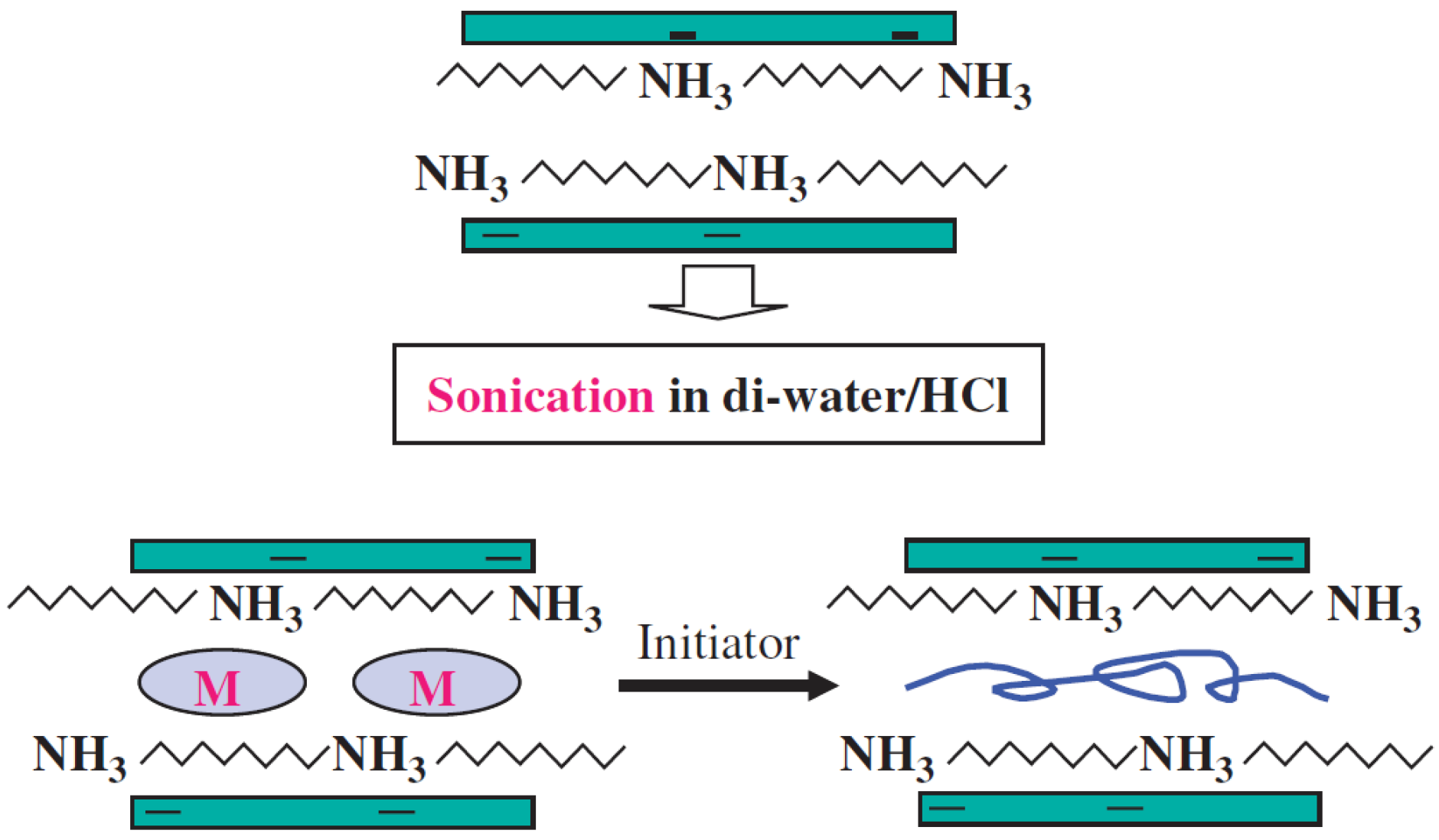
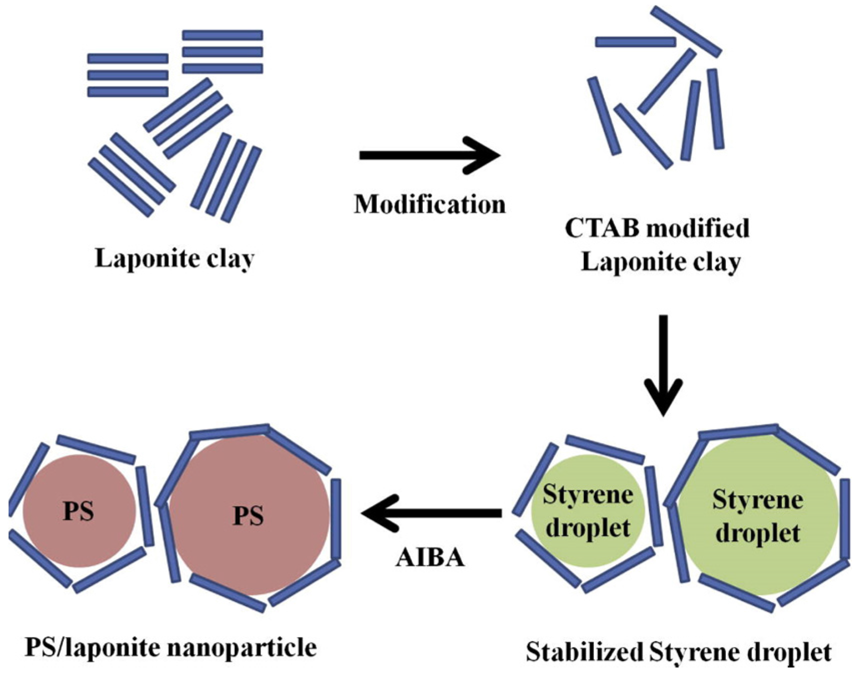
1.1.4. Pickering Emulsion Polymerization
1.2. Melt Processing
2. Characterization of Polymer-Clay Nanocomposites
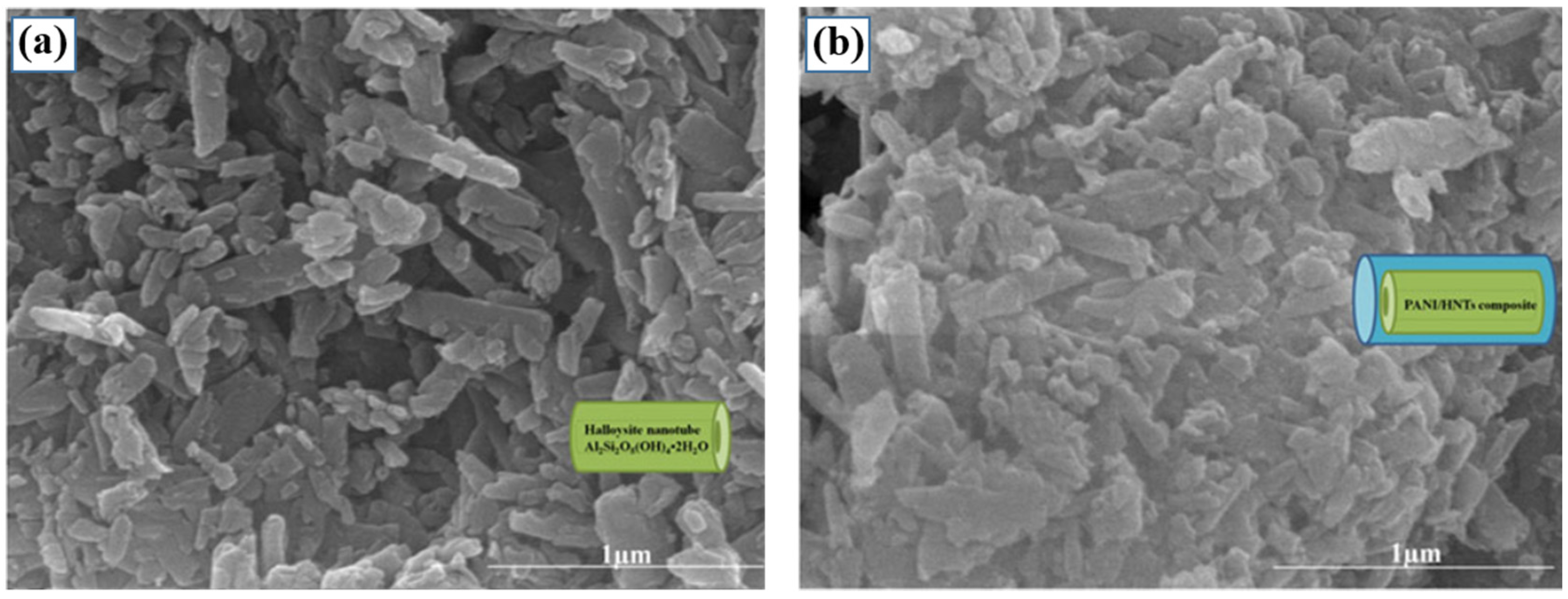
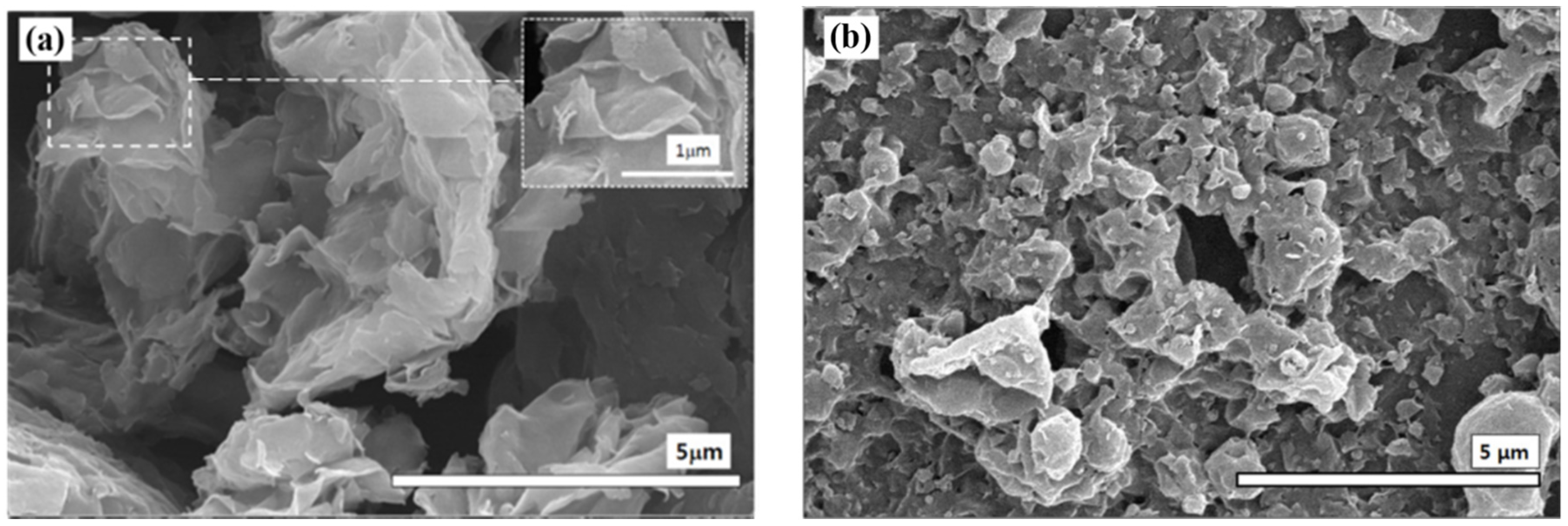
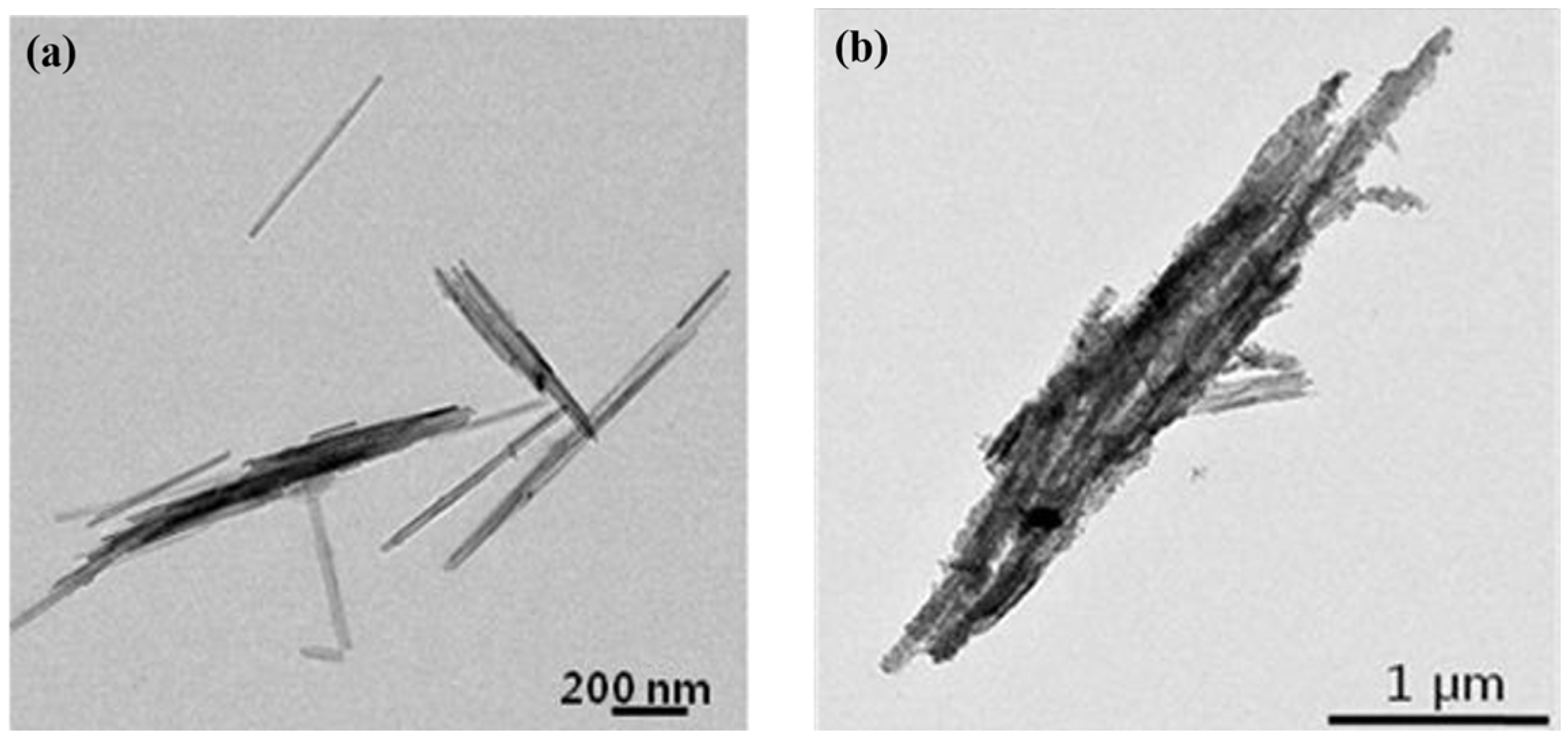
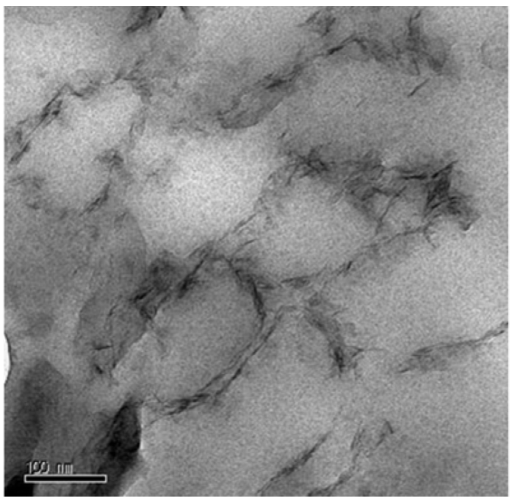
2.1. Morphology


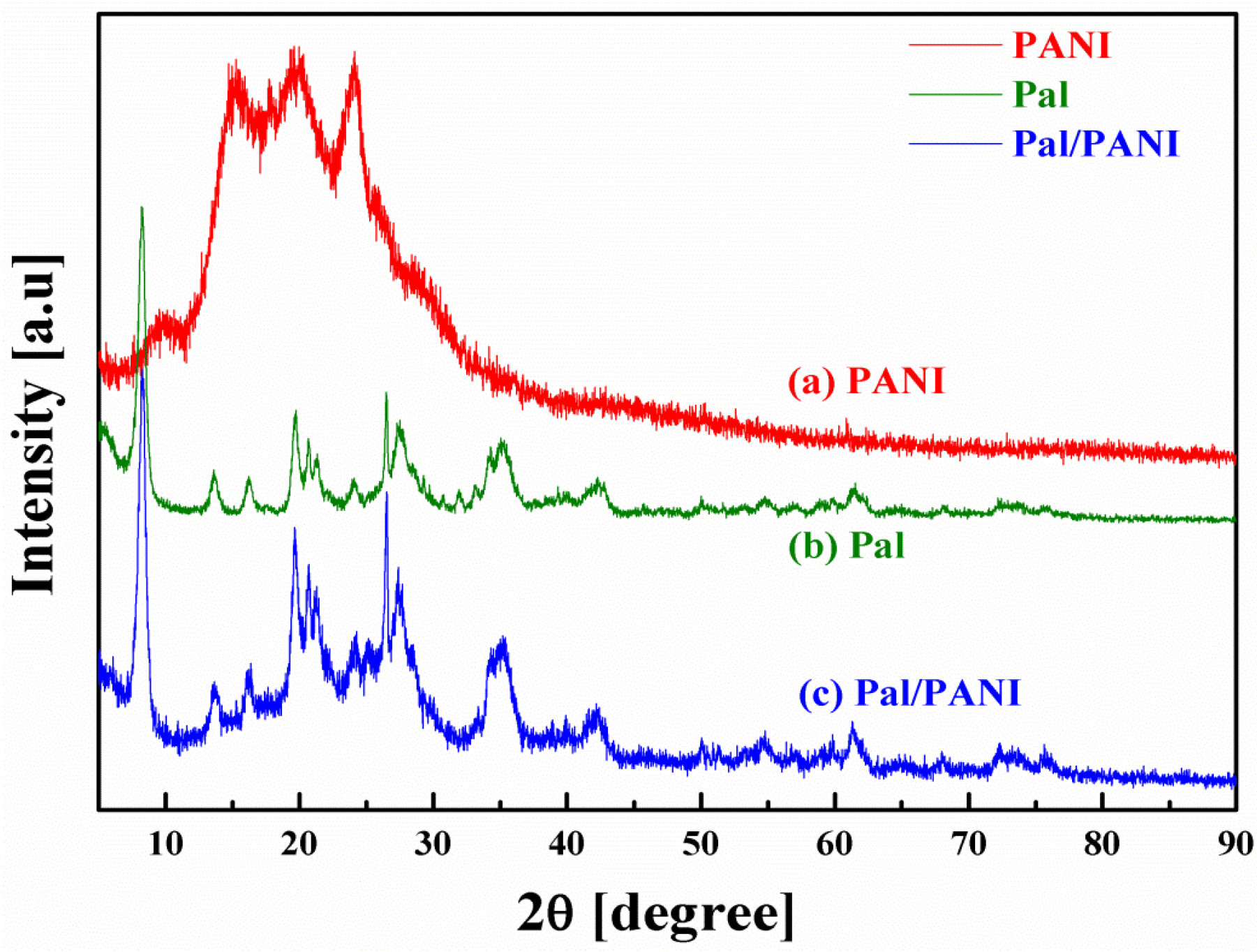
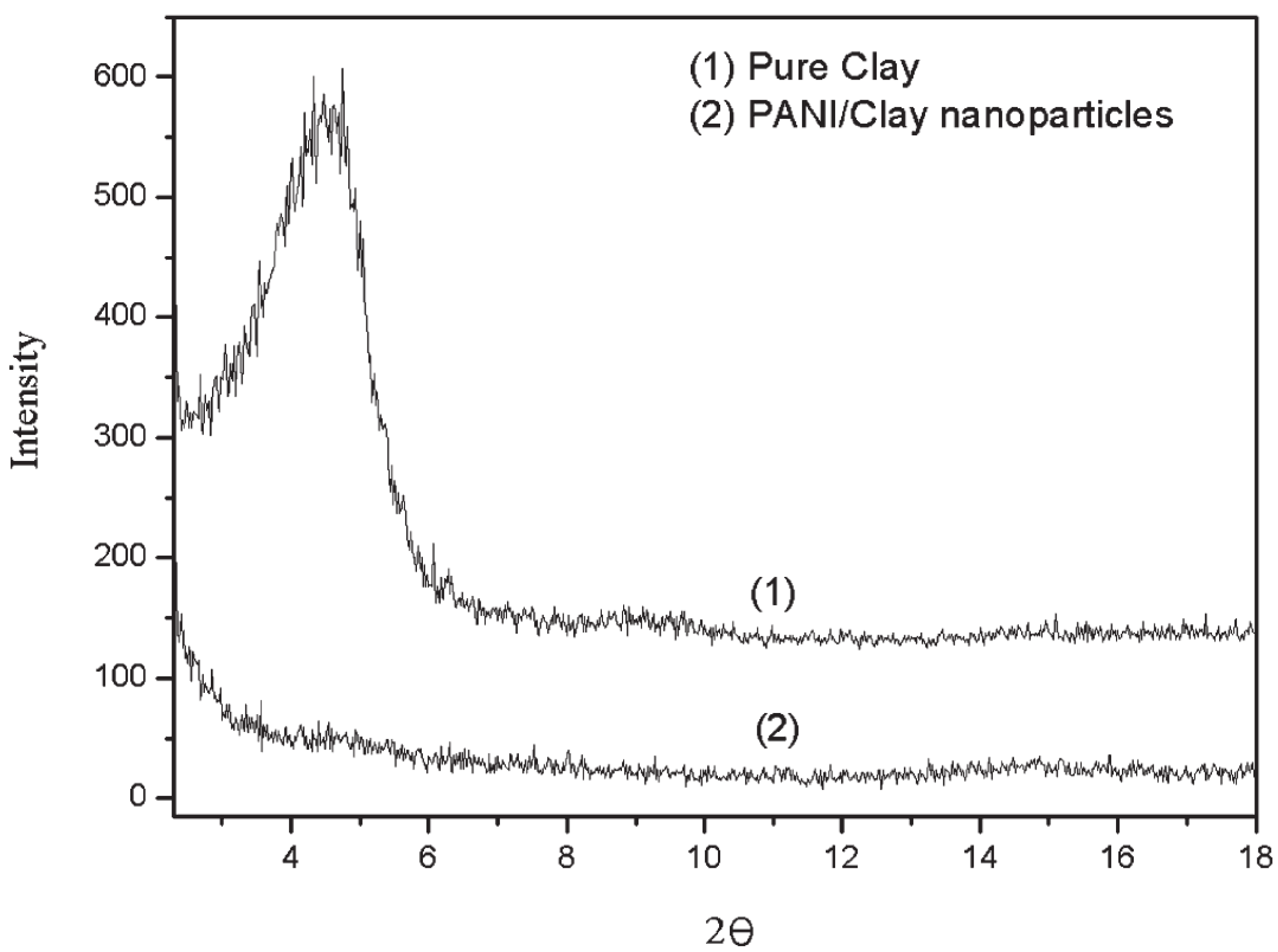
2.2. Crystalline State

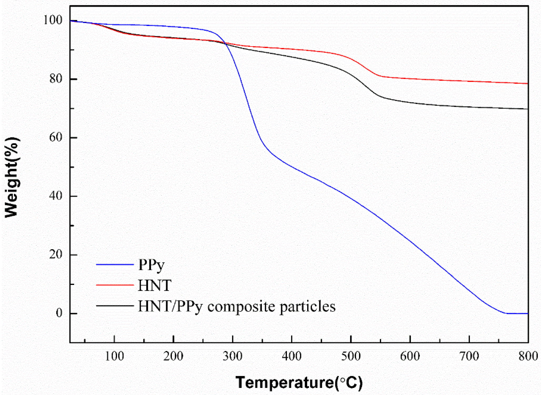
2.3. Thermal Properties
3. Electrorheological (ER) Characteristics


| Polymer/Clay Nanocomposites | Fabrication Method | Clay Content (wt %) | Slope of Dynamic Yield Stress | Reference |
|---|---|---|---|---|
| PANI/MMT | In-situ polymerization | 0.75–3 | - | [41] |
| PEA/MMT | In-situ polymerization | 0.5–5 | - | [42] |
| PUA/MMT | Suspension polymerization | 5 | - | [47] |
| SAN/MMT | Emulsion polymerization | 4.76 | - | [49] |
| PANI/OMMT | Pickering emulsion polymerization | - | 1.5 | [52] |
| PIN/OMMT | In-situ polymerization | 5.5–12.1 | - | [81] |
| PIN/kaolinite | cationic radical polymerization | 15–78 | - | [80] |
| PANI/HNT | In-situ polymerization | - | 2 | [45] |
| PPy/HNT | In-situ polymerization | - | 1.5 | [68] |
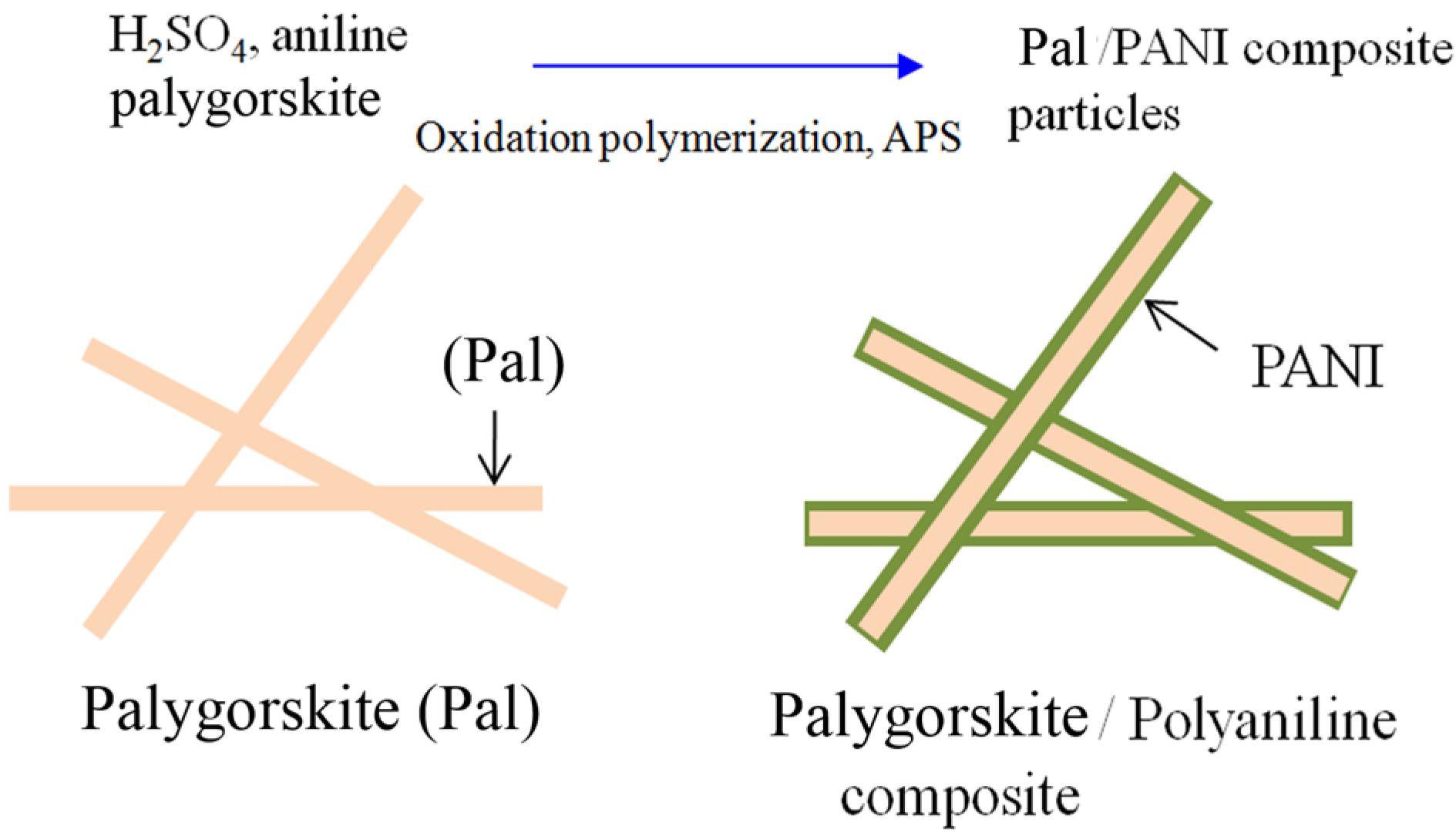
| PANI/PAL | In-situ polymerization | - | 2 | [46] |
| PS/laponite | Pickering emulsion polymerization | 8.85 | 1.2 | [53] |
4. Conclusions
Acknowledgments
Author Contributions
Conflicts of Interest
References
- Abranyi, A.; Szazdi, L.; Pukanszky, B.; Vancso, G.J.; Pukansky, B. Formation and detection of clay network structure in Poly(propylene)/layered silicate nanocomposites. Macromol. Rapid Commun. 2006, 27, 132–165. [Google Scholar] [CrossRef]
- Messersmith, P.B.; Giannelis, E.P. Synthesis and characterization of layered silicate-expoxy nanocomposites. Chem. Mater. 1994, 6, 1719–1725. [Google Scholar] [CrossRef]
- Ray, S.S.; Okamoto, M. Biodegradable polylactide and its nanocomposites: Opening a new dimension for plastics and composites. Macromol. Rapid Commun. 2003, 24, 815–840. [Google Scholar] [CrossRef]
- Kuksenok, O.V.; Ruhwandl, R.W.; Shiyanovskii, S.V.; Terentjev, E.M. Director structure around a colloid particle suspended in a nematic liquid crystal. Phys. Rev. 1996, 54, 5198–5203. [Google Scholar] [CrossRef]
- Chang, Y.M.; Tsai, Y.Y.; Huang, Y.P.; Chen, W.S.; Lee, W. Electrical and electro-optical properties of nematic-liquid-crystal-montmorillonite-clay nanocomposites. Jpn. J. Appl. Phys. 2007, 46, 7368–7370. [Google Scholar] [CrossRef]
- Lim, S.T.; Hyun, Y.H.; Choi, H.J.; Jhon, M.S. Synthetic biodegradable aliphatic polyester/montmorillonite nanocomposites. Chem. Mater. 2002, 14, 1839–1844. [Google Scholar] [CrossRef]
- Alexandre, M.; Beyer, G.; Henrist, C.; Cloots, R.; Rulmant, A.; Jerome, R.; Dubois, P. Preparation and properties of layered silicate nanocomposites based on ethylene vinyl acetate copolymers. Macromol. Rapid Commun. 2001, 22, 643–646. [Google Scholar] [CrossRef]
- Hyun, Y.H.; Lim, S.T.; Choi, H.J.; Jhon, M.S. Rheology of poly(ethylene oxide)/organoclay nanocomposites. Macromolecules 2001, 34, 8084–8093. [Google Scholar] [CrossRef]
- Fong, H.; Vaia, R.A.; Sanders, J.H.; Lincoln, D.; Vreugdenhil, A.J.; Liu, W.D.; Bultman, J.; Chen, C.G. Self-passivation of polymer-layered silicate nanocomposites. Chem. Mater. 2001, 13, 4123–4129. [Google Scholar] [CrossRef]
- Chen, B.Q.; Evans, J.R.G.; Greenwell, H.C.; Boulet, P.; Coveney, P.V.; Bowden, A.A.; Whiting, A. A critical appraisal of polymer-clay nanocomposites. Chem. Soc. Rev. 2008, 37, 568–594. [Google Scholar] [CrossRef] [PubMed]
- Chen, G.M.; Liu, S.H.; Zhang, S.F.; Qi, Z.N. Self-assembly in a polystyrene/montmorillonite nanocomposite. Macromol. Rapid Commun. 2008, 21, 746–749. [Google Scholar] [CrossRef]
- Wang, K.; Liang, S.; Du, R.N.; Zhang, Q.; Fu, Q. The interplay of thermodynamics and shear on the dispersion of polymer nanocomposite. Polymer 2004, 45, 7953–7960. [Google Scholar] [CrossRef]
- Faguy, P.W.; Lucas, R.A.; Ma, W.L. An FT-IR-ATR spectroscopic study of the spontaneous polymerization of pyrrole in iron-exchanged montmorillonite. Colloid. Surf. Sci. A 1995, 105, 105–112. [Google Scholar] [CrossRef]
- Carrado, K.A.; Xu, L.Q. In situ synthesis of polymer-clay nanocomposites from silicate gels. Chem. Mater. 1998, 10, 1440–1445. [Google Scholar] [CrossRef]
- Ballav, N.; Sardar, P.S.; Ghosh, S.; Biswas, M. Polyaniline and polypyrrole modified conductive nanocomposites of polyfuran and polythiophene with montmorillonite clay. J. Ind. Eng. Chem. 2006, 41, 2959–2964. [Google Scholar] [CrossRef]
- Masdarolomoor, F.; Innis, P.C.; Ashraf, S.; Kaner, R.B.; Walace, G.G. Nanocomposites of polyaniline/poly (2-methoxyaniline-5-sulfonic acid). Macromol. Rapid Commun. 2006, 27, 1995–2000. [Google Scholar] [CrossRef]
- Yeh, J.M.; Chin, C.P.; Chang, S. Enhanced corrosion protection coatings prepared from soluble electronically conductive polypyrrole-clay nanocomposite materials. J. Appl. Polym. Sci. 2003, 88, 3264–3272. [Google Scholar] [CrossRef]
- Choi, H.J.; Kim, S.G.; Hyun, Y.H.; Jhon, M.S. Preparation and rheological characteristics of solvent-cast poly(ethylene oxide)-montmorillonite nanocomposites. Macromol. Rapid Commun. 2001, 22, 320–325. [Google Scholar] [CrossRef]
- Ogawa, M.; Ishii, T.; Miyamoto, N.; Kuroda, K. Intercalation of a cationic azobenzene into montmorillonite. Appl. Clay Sci. 2003, 22, 179–185. [Google Scholar] [CrossRef]
- Ray, S.S.; Yamada, K.; Okamoto, M.; Ueda, K. Control of biodegradability of polylactide via nanocomposite technilogy. Macromol. Mater. Eng. 2003, 288, 203–208. [Google Scholar] [CrossRef]
- Tjong, S.C.; Meng, Y.Z.; Hay, A.S. Novel preparation and properties of polypropylene-vermiculite nanocomposites. Chem. Mater. 2002, 14, 44–51. [Google Scholar] [CrossRef]
- Manias, E.; Touny, A.; Wu, L.; Strawhecker, K.; Lu, B.; Chung, T.C. Polypropylene/montmorillonite nanocomposites. Review of the synthetic routes and materials properties. Chem. Mater. 2001, 13, 3516–3523. [Google Scholar] [CrossRef]
- Caseri, W. Nanocomposites of polymers and metals or semiconductors: Historical background and optical properties. Macromol. Rapid Commun. 2000, 21, 705–722. [Google Scholar] [CrossRef]
- Leroux, F.; Besse, J.P. Polymer interleaved layered double hydroxide: A new emerging class of nanocomosites. Chem. Mater. 2001, 13, 3507–3515. [Google Scholar] [CrossRef]
- Fang, F.F.; Choi, H.J.; Joo, J. Conducting polymer/clay nanocomposites and their applications. J. Nanosci. Nanotechnol. 2008, 8, 1559–1581. [Google Scholar] [CrossRef] [PubMed]
- Zhao, X.P.; Yin, J.B. Preparation and electrorheological characteristics of rare-earth-doped TiO2 suspensions. Chem. Mater. 2002, 14, 2258–2263. [Google Scholar] [CrossRef]
- Loudet, J.C.; Poulin, P. Application of an electric field to colloidal particles suspended in a liquid-crystal solvent. Phys. Rev. Lett. 2001, 87, 165503. [Google Scholar] [CrossRef] [PubMed]
- Oz, K.; Yavuz, M.; Yilmaz, H.; Unal, H.I.; Sari, B. Electrorheological properties and creep behavior of polyindole/poly(vinyl acetate) composite suspensions. J. Mater. Sci. 2008, 43, 1451–1459. [Google Scholar] [CrossRef]
- Cheng, Y.C.; Guo, J.J.; Xu, G.J.; Cui, P.; Liu, X.H.; Liu, F.H.; Wu, J.H. Electrorheological property and microstructure of acetamide-modified TiO2 nanoparticles. Colloid Polym. Sci. 2008, 286, 1493–1497. [Google Scholar] [CrossRef]
- Chin, B.D.; Lee, Y.S.; Park, O.O. Dielectric and rheological behaviors of semiconductive polymer suspension as an electrorheological fluid. J. Mod. Phys. B 1999, 13, 1852–1859. [Google Scholar] [CrossRef]
- Kim, S.G.; Kim, J.W.; Jang, W.H.; Choi, H.J.; Jhon, M.S. Electrorheological characteristics of phosphate cellulose-based suspensions. Polymer 2001, 42, 5005–5012. [Google Scholar] [CrossRef]
- Kim, J.W.; Liu, F.; Choi, H.J. Polypyrrole/clay nanocomposite and its electrorheological characteristics. J. Ind. Eng. Chem. 2002, 8, 399–403. [Google Scholar]
- Wen, W.J.; Huang, X.X.; Sheng, P. Electrorheological fluids, structures and mechanisms. Soft Matter 2008, 4, 200–210. [Google Scholar] [CrossRef]
- Lei, X.P.; Liu, Y.S.; Su, Z.X. Synthesis and characterization of organo-attapulgite/polyaniline-dodecylbenzenesulfonic acid based on emulsion polymerization method. Polym. Compos. 2008, 29, 239–244. [Google Scholar] [CrossRef]
- Chin, B.D.; Park, J.H.; Kwon, M.H.; Park, O.O. Rheological properties and dispersion stability of magnetorheological (MR) suspensions. Rheol. Acta 2001, 40, 211–219. [Google Scholar] [CrossRef]
- Park, J.H.; Chin, B.D.; Park, O.O. Rheological properties and stabilization of magnetorheological fluids in a water-in-oil emulsion. J. Colloid Interf. Sci. 2001, 240, 349–354. [Google Scholar] [CrossRef] [PubMed]
- Lim, S.T.; Cho, M.S.; Jang, I.B.; Choi, H.J. Magnetorheological characterization of carbonyl iron based suspension stabilized by fumed silica. J. Magn. Magn. Mater. 2004, 282, 170–173. [Google Scholar] [CrossRef]
- Bossis, G.; Abbo, C.; Cutillas, S.; Lacis, S.; Métayer, C. Electroactive and electrostructured elastomers. Int. J. Mod. Phys. B 2001, 15, 564–573. [Google Scholar] [CrossRef]
- Kim, J.W.; Kim, C.A.; Choi, H.J.; Choi, S.B. Role of surfactant on damping performance of polyaniline based electrorheological suspension. Korea Aust. Rheol. J. 2006, 18, 25–30. [Google Scholar]
- Ruiz-Hitzky, E.; Aranda, P.; Casal, B.; Galván, J.C. Nanocomposite materials with controlled ion mobility. Adv. Mater. 1995, 7, 180–184. [Google Scholar] [CrossRef]
- Yeh, J.M.; Liou, S.J.; Lai, C.Y.; Wu, P.C. Enhancement of corrosion protection effect in polyaniline via the formation of polyaniline-clay nanocomposite materials. Chem. Mater. 2001, 13, 1131–1136. [Google Scholar] [CrossRef]
- Yeh, J.M.; Chen, C.L.; Chen, Y.C.; Ma, C.Y.; Lee, K.R.; Wei, Y.; Li, S.X. Enhancement of corrosion protection effect of poly(o-ethoxyaniline) via the formation of poly (o-ethoxyaniline)-clay nanocomposite materials. Polymer 2002, 43, 2729–2736. [Google Scholar] [CrossRef]
- Zhou, C.; Du, X.; Liu, Z.; Mai, Y.W.; Ringer, S.P. Multi-holed clay nanotubes and their modification with a polyaniline nanolayer. J. Mater. Sci. 2011, 46, 446–450. [Google Scholar] [CrossRef]
- Zhang, L.; Wang, T.; Liu, P. Polyaniline-coated halloysite nanotubes via in-situ chemical polymerization. Appl. Surf. Sci. 2008, 255, 2091–2097. [Google Scholar] [CrossRef]
- Zhang, W.L.; Choi, H.J. Fabrication of semiconducting polyaniline-wrapped halloysite nanotube composite and its electrorheology. Colloid Polym. Sci. 2012, 290, 1743–1748. [Google Scholar] [CrossRef]
- Chae, H.S.; Zhang, W.L.; Piao, S.H.; Choi, H.J. Synthesized palygorskite/polyaniline nanocomposite particles by oxidative polymerization and their electrorheology. Appl. Clay Sci. 2015, 107, 165–172. [Google Scholar] [CrossRef]
- Jun, J.B.; Suh, K.D. Preparation and electrorheological characterization of suspensions of poly(urethane acrylate)/clay nanocomposite particles. J. Appl. Polym. Sci. 2003, 90, 458–464. [Google Scholar] [CrossRef]
- Tong, X.; Zhao, H.; Tang, T.; Feng, Z.; Huang, B. Preparation and characterization of poly(ethyl acrylate)/bentonite nanocomposites by in situ emulsion polymerization. J. Polym. Sci. A Polym. Chem. 2002, 40, 1706–1711. [Google Scholar] [CrossRef]
- Kim, J.W.; Jang, L.W.; Choi, H.J.; Jhon, M.S. Physical and electroresponsive characteristics of the intercalated styrene-acrylonitrile copolymer/clay nanocomposite under applied electric fields. J. Appl. Polym. Sci. 2003, 89, 821–827. [Google Scholar] [CrossRef]
- Tang, J.; Quinlan, P.J.; Tam, K.C. Stimuli-responsive Pickering emulsions: Recent advances and potential applications. Soft Matter 2015, 11, 3512–3529. [Google Scholar] [CrossRef] [PubMed]
- Piao, S.H.; Kwon, S.H.; Zhang, W.L.; Choi, H.J. Celebrating soft matter’s 10th anniversary: Stimuli-responsive Pickering emulsion polymerized smart fluids. Soft Matter 2015, 11, 646–654. [Google Scholar] [CrossRef] [PubMed]
- Fang, F.F.; Liu, Y.D.; Choi, H.J. Synthesis and electrorheological characteristics of polyaniline/organoclay nanoparticles via Pickering emulsion polymerization. Smart Mater. Struct. 2010, 19, 124002. [Google Scholar] [CrossRef]
- Kim, Y.J.; Liu, Y.D.; Choi, H.J.; Park, S.J. Facile fabrication of Pickering emulsion polymerized polystyrene/laponite composite nanoparticles and their electrorheology. J. Colloid Interf. Sci. 2013, 394, 108–114. [Google Scholar] [CrossRef] [PubMed]
- Park, J.U.; Choi, Y.S.; Cho, K.S.; Kim, D.H.; Ahn, K.H.; Lee, S.J. Time–electric field superposition in electrically activated polypropylene/layered silicate nanocomposites. Polymer 2006, 47, 5145–5153. [Google Scholar] [CrossRef]
- Kim, D.H.; Park, J.U.; Cho, K.S.; Ahn, K.H.; Lee, S.J. A novel fabrication method for poly(propylene)/clay nanocomposites by continuous processing. Macromol. Mater. Eng. 2006, 291, 1127–1135. [Google Scholar] [CrossRef]
- Strounina, E.V.; Shepherd, R.; Kane-Maguire, L.A.P.; Wallace, G.G. Conformational changes in sulfonated polyaniline caused by metal salts and OH−. Synth. Met. 2003, 135/136, 289–290. [Google Scholar] [CrossRef]
- Bon, S.A.F.; Chen, T. Pickering stabilization as a tool in the fabrication of complex nanopatterned silica microcapsules. Langmuir 2007, 23, 9527–9530. [Google Scholar] [CrossRef] [PubMed]
- Bon, S.A.F.; Chen, T. Pickering miniemulsion polymerization using laponite clay as a stabilizer. Langmuir 2007, 23, 8316–8322. [Google Scholar] [CrossRef] [PubMed]
- Negrete-Herrera, N.; Putaux, J.L.; David, L.; Bourgeat-Lami, E. Polymer/laponite composite colloids through emulsion polymerization: Influence of the clay modification level on particle morphology. Macromolecules 2006, 39, 9177–9184. [Google Scholar] [CrossRef]
- Fang, F.F.; Kim, J.H.; Choi, H.J.; Kim, C.A. Synthesis and electrorheological response of nano-sized laponite stabilized poly(methyl methacrylate) spheres. Colloid Polym. Sci. 2009, 287, 745–749. [Google Scholar] [CrossRef]
- Fang, F.F.; Choi, H.J.; Seo, Y.S. Novel fabrication of polyaniline particles wrapped by exfoliated clay sheets and their electrorheology. J. Nanosci. Nanotechnol. 2009, 9, 1–5. [Google Scholar] [CrossRef]
- Vaia, R.A.; Giannelis, E.P. Polymer melt intercalation in organically-modified layered silicates: Model predictions and experiment. Macromolecules 1997, 30, 8000–8009. [Google Scholar] [CrossRef]
- Lee, D.K.; Lee, S.H.; Char, K.; Kim, J. Expansion distribution of basal spacing of the silicate layers in polyaniline/Na-montmorillonite nanocomposites monitored with X-ray diffraction. Macromol. Rapid Commun. 2000, 21, 1136–1139. [Google Scholar] [CrossRef]
- Jin, E.; Lu, X.F.; Bian, X.J.; Kong, L.R.; Zhang, W.J.; Wang, C. Unique tetragonal starlike polyanilinemicrostructure and its application in electrochemical biosensing. J. Mater. Chem. 2010, 20, 3079–3083. [Google Scholar] [CrossRef]
- Wang, J.H.; Han, X.J.; Ma, H.R.; Ji, Y.F.; Bi, L.J. Adsorptive removal of humic acid from aqueous solution on polyaniline/attapulgite composite. Chem. Eng. J. 2011, 173, 171–177. [Google Scholar] [CrossRef]
- Agag, T.; Koga, T.; Takeichi, T. Thermal and mechanical properties of polyimide-clay nanocomposites. Polymer 2001, 42, 3399–3408. [Google Scholar] [CrossRef]
- Jang, B.Z. Control of interfacial adhesion in continuous carbon and Kevlar fiber reinforced polymer composites. Compos. Sci. Technol. 1992, 44, 333–349. [Google Scholar] [CrossRef]
- Jang, D.S.; Zhang, W.L.; Choi, H.J. Polypyrrole-wrapped halloysite nanocomposite and its rheological response under electric fields. J. Mater. Sci. 2014, 49, 7309–7316. [Google Scholar] [CrossRef]
- Jang, J.S.; Yoon, H.S. Novel fabrication of size-tunable silica nanotubes using a reverse-microemulsion-mediated sol–gel method. Adv. Mater. 2004, 16, 799–802. [Google Scholar] [CrossRef]
- Nicolini, K.P.; Fukamachi, C.R.B.; Wypych, F.; Mangrich, A.S. Dehydrated halloysite intercalated mechanochemically with urea: Thermal behavior and structural aspects. J. Colloid Interface Sci. 2009, 338, 474–479. [Google Scholar] [CrossRef] [PubMed]
- Park, D.P.; Lim, S.T.; Lim, J.Y.; Choi, H.J.; Choi, S.B. Electrorheological characteristics of solvent-cast polypyrrole/clay nanocomposite. J. Appl. Polym. Sci. 2009, 112, 1365–1371. [Google Scholar] [CrossRef]
- Parthasarathy, M.; Klingenberg, D.J. Electrorheology: Mechanisms and models. Mater. Sci. Eng. 1996, 17, 57–103. [Google Scholar] [CrossRef]
- Davis, L.C. Polarization forces and conductivity effects in electrorheological fluids. J. Appl. Phys. 1992, 72, 1334–1340. [Google Scholar] [CrossRef]
- Hao, T.; Kawai, A.; Ikazaki, F. Mechanism of the electrorheological effect—Evidence from the conductive, dielectric, and surface characteristics of water-free electrorheological fluids. Langmuir 1998, 14, 1256–1262. [Google Scholar] [CrossRef]
- Cho, M.S.; Cho, Y.H.; Choi, H.J.; Jhon, M.S. Synthesis and electrorheological characteristics of polyaniline-coated poly(methyl methacrylate) microsphere: Size effect. Langmuir 2003, 19, 5875–5881. [Google Scholar] [CrossRef]
- Cho, M.S.; Choi, H.J.; Jhon, M.S. Shear stress analysis of a semiconducting polymer based electrorheological fluid system. Polymer 2005, 46, 11484–11488. [Google Scholar] [CrossRef]
- Choi, H.J.; Park, S.H.; Yoon, J.S.; Lee, H.S.; Choi, S.J. Rheological study on poly-D(-)(3-hydroxybutyrate) and its blends with poly(ethylene oxide). Polym. Eng. Sci. 1995, 35, 1636–1642. [Google Scholar] [CrossRef]
- Fang, F.F.; Liu, Y.D.; Lee, I.S.; Choi, H.J. Well controlled core/shell type polymeric microspheres coated with conducting polyaniline: Fabrication and electrorheology. RSC Adv. 2011, 1, 1026–1032. [Google Scholar] [CrossRef]
- Erol, O.; Karakisla, M.; Unal, H.I.; Sacak, M. Electrorheological properties of polyaniline/K-feldspar conducting composite. J. Compos. Mater. 2012, 46, 1295–1304. [Google Scholar] [CrossRef]
- Eristi, C.; Yavus, M.; Yilmaz, H.; Sari, B.; Unal, H.I. Synthesis, characterization and electrorheological properties of polyindene/kaolinite composites. J. Macromol. Sci. A Pure Appl. Chem. 2007, 44, 759–767. [Google Scholar] [CrossRef]
- Guzel, S.; Erol, O.; Unal, H.I. Polyindene/Organo-montmorillonite conducting nanocomposites. II. Electrorheological properties. J. Appl. Polym. Sci. 2012, 124, 4935–4944. [Google Scholar] [CrossRef]
- Lu, J.; Zhao, X.P. Electrorheological properties of suspensions based on polyaniline-montmorillonite clay nanocomposite. J. Mater. Res. 2002, 17, 1513–1519. [Google Scholar] [CrossRef]
- Erol, O.; Unal, H.I.; Sari, B. Synthesis, electrorheology, and creep behaviors of in situ intercalated polyindole/organo-montmorillonite conducting nanocomposite. Polym. Compos. 2010, 31, 471–481. [Google Scholar]
- Yin, J.B.; Xia, X.; Zhao, X.P. The electrorheological effect and dielectric properties of suspensions containing polyaniline@tutania nanocable-like particles. Soft Matter 2011, 7, 10978–10986. [Google Scholar] [CrossRef]
- Liu, C.; Li, C.; Chen, P.; He, J.; Fan, Q. Influence of long-chain branching on linear viscoelastic flow properties and dielectric relaxation of polycarbonates. Polymer 2004, 45, 2803–2812. [Google Scholar] [CrossRef]
- Pluta, M.; Jeszka, J.K.; Boiteux, G. Polylactide/montmorillonite nanocomposites: Structure, dielectric, viscoelastic and thermal properties. Eur. Polym. J. 2007, 43, 2819–2835. [Google Scholar] [CrossRef]
- Xu, J.; Wong, C.P. Characterization and properties of an organic-inorganic dielectric nanocomposite for embedded decoupling capacitor applications. Compos. A 2007, 38, 13–19. [Google Scholar] [CrossRef]
- Liu, Y.D.; Fang, F.F.; Choi, H.J. Silica nanoparticle decorated polyaniline nanofiber and its electrorheological response. Soft Matter 2011, 7, 2782–2789. [Google Scholar] [CrossRef]
- Schwarzl, F.L. Numerical calculation of stress relaxation modulus from dynamic data for linear viscoelastic materials. Rheol. Acta 1975, 14, 581–590. [Google Scholar] [CrossRef]
© 2016 by the authors; licensee MDPI, Basel, Switzerland. This article is an open access article distributed under the terms and conditions of the Creative Commons by Attribution (CC-BY) license (http://creativecommons.org/licenses/by/4.0/).
Share and Cite
Piao, S.H.; Kwon, S.H.; Choi, H.J. Stimuli-Responsive Polymer-Clay Nanocomposites under Electric Fields. Materials 2016, 9, 52. https://doi.org/10.3390/ma9010052
Piao SH, Kwon SH, Choi HJ. Stimuli-Responsive Polymer-Clay Nanocomposites under Electric Fields. Materials. 2016; 9(1):52. https://doi.org/10.3390/ma9010052
Chicago/Turabian StylePiao, Shang Hao, Seung Hyuk Kwon, and Hyoung Jin Choi. 2016. "Stimuli-Responsive Polymer-Clay Nanocomposites under Electric Fields" Materials 9, no. 1: 52. https://doi.org/10.3390/ma9010052