
Electrochemical Behavior of Al-B4C Metal Matrix Composites in NaCl Solution

Department of Applied Sciences, Université du Québec à Chicoutimi, 555 boul. de l’Université, Saguenay, QC G7H 2B1, Canada
*
Author to whom correspondence should be addressed.
Materials 2015, 8(9), 6455-6470; https://doi.org/10.3390/ma8095314
Submission received: 21 August 2015
/
Revised: 13 September 2015
/
Accepted: 15 September 2015
/
Published: 21 September 2015
(This article belongs to the Section Advanced Composites)
Abstract
:Aluminum based metal matrix composites (MMCs) have received considerable attention in the automotive, aerospace and nuclear industries. One of the main challenges using Al-based MMCs is the influence of the reinforcement particles on the corrosion resistance. In the present study, the corrosion behavior of Al-B4C MMCs in a 3.5 wt.% NaCl solution were investigated using potentiodynamic polarization (PDP) and electrochemical impedance spectroscopy (EIS) techniques. Results indicated that the corrosion resistance of the composites decreased when increasing the B4C volume fraction. Al-B4C composite was susceptible to pitting corrosion and two types of pits were observed on the composite surface. The corrosion mechanism of the composite in the NaCl solution was primarily controlled by oxygen diffusion in the solution. In addition, the galvanic couples that formed between Al matrix and B4C particles could also be responsible for the lower corrosion resistance of the composites.
1. Introduction
Aluminum based metal matrix composites (MMCs) have received considerable attention in the automotive, aerospace and nuclear industries due to their light weight, as well as their superior thermal conductivity, high stiffness and hardness [1,2,3]. The common reinforcements added to commercial MMCs are silicon carbide (SiC), alumina (Al2O3) and boron carbide (B4C). Compared to traditional SiC and Al2O3 reinforcements, B4C possesses numerous advantages, specifically a density (2.51 g·cm−3) [4] that is significantly lower than that of SiC or Al2O3, an extremely high hardness (HV = 30 GPa) and wear resistance, a remarkable chemical inertness [4,5,6,7] and a special neutron absorption capacity [8]. These features make B4C an excellent reinforcement for high performance MMCs. Its applications include hard disc substrates, brakes with a high wear resistance and armor plates with a high ballistic performance [9,10]. In recent years, due to the special capturing neutron ability of isotope B10, Al-B4C MMCs have been increasingly used as neutron shielding materials when fabricating storage containers for spent nuclear fuels in the nuclear industry [11,12,13,14].
One of the main challenges using Al-based MMCs is the influence of the reinforcement particles on the corrosion resistance [15,16,17,18,19]. Because adding reinforcement particles interrupts the continuity of the aluminum matrix and its protective surface oxide films, the number of sites where corrosion could be initiated increases, making the composite more susceptible to corrosion [20,21]. Singh et al. [22] studied the influence of SiC particles addition on the corrosion behavior of 2014 Al-Cu alloy in 3.5 wt.% NaCl solution. They found that addition of 25 wt.% SiCp to base alloy decreases corrosion resistances considerably. Zhu and Hihara [23] investigated the influence of alumina fiber on the corrosion initiation and propagation of the Al-2 wt.% Cu-T6 metal matrix composite. Results show that the MMC exhibited inferior corrosion resistance as compared to its monolithic matrix alloy. Bhat et al. [24] investigated the corrosion behavior of the 6061 Al-SiCp composite and its base alloy in seawater using the potentiodynamic polarization technique. It was found that the composite corroded faster than its base alloy and that composite corrosion was mainly confined to the interface as opposed to the uniform corrosion observed for the base alloy. Sun et al. [25] also studied the corrosion behavior of 6061 Al-SiCp MMCs in a NaCl solution. With the observation that the pitting degree rose with an increasing SiC content, it is presumed that the pitting corrosion depends on the local SiC distribution and the surface film integrity. Roepstorff et al. [26] reported that the corrosion resistance of metal matrix composites can be affected by three processes: (1) galvanic coupling of the metal and reinforcement; (2) crevice attack at the metal/reinforcement interface; and (3) preferred localized attack on the possible reaction products between the metal and the ceramic.
In contrast to the many research works dedicated to the corrosion behavior of Al-SiC composites, few studies have focused on the corrosion of Al-B4C composites. Ding and Hihara [27] investigated the effect of B4C particles on the corrosion behavior of 6092-T6 Al MMCs with 20 vol.% B4C in a 0.5 M Na2SO4 solution at room temperature. Corrosion initiation and propagation are related to the formation of microcrevices, the localized acidification and alkalization of the solution, and to aluminum containing amphoteric oxides. Katkar et al. [28] evaluated the effect of the reinforced B4C particle content in AA6061 on the formation of a passive film in sea water. They reported that the passive film formed on B4C particle-reinforced AA6061 alloy because there was a shift in the corrosion potential toward the positive direction compared to the base alloy. In our previous study [29], the Al-B4C composite was less corrosion resistant than the base alloy in the NaCl, K2SO4 and H3BO3 solutions. In another study [30], the B4C particles exhibited a cathodic character relative to the aluminum alloy in the K2SO4 solution, meaning that the B4C particles could form galvanic couples with the peripheral aluminum matrix in the composite.
To have a deep understanding of the corrosion behavior and corrosion mechanism of AA1100-B4C metal matrix composites in a 3.5 wt.% NaCl solution, the present study was carried out in open-to-air and deoxygenated conditions. Electrochemical techniques, including potentiodynamic polarization (PDP), electrochemical impedance spectroscopy (EIS) and zero resistance ammetry (ZRA) were used. Besides, the effect of the B4C particle volume fraction on the corrosion behavior of Al-B4C composites was investigated, and the surface morphology of the composite before and after corrosion was characterized using an optical stereoscope and a scanning electron microscope (SEM).
2. Experimental Procedures
2.1. Preparation of Samples and Electrolytes
The investigated composites were AA1100-16 vol.% B4C and AA1100-30 vol.%. Both composites were supplied by Rio Tinto Alcan (Saguenay, QC, Canada) via an ingot metallurgy route [3,9]. The average particle size of boron carbide in the composites is 17 μm and the matrix is a standard AA1100 aluminum alloy except the Ti content. Approximately 1.0–2.5 wt.% titanium was added to both Al-B4C composites during the composite fabrication process to reduce the interfacial reactions between the B4C and the liquid aluminum [31]. The DC cast ingots were preheated and hot-rolled with multi-passes of cross-rolling to the final 4.3 mm thick sheets. To study the effect of B4C particles on the corrosion behavior of the composite, an AA1100 alloy without B4C was used as the base alloy. The chemical composition of the AA1100 base alloy is listed in Table 1.

| Elements | Fe | Si | Cu | Mn | Mg | Zn | Al |
|---|---|---|---|---|---|---|---|
| Composition (wt.%) | 0.15 | 0.10 | 0.05 | 0.02 | 0.001 | 0.01 | Bal. |
Samples were cut into small pieces (20 mm by 20 mm) and unless otherwise stated, sanded with a 3M Scotch-Brite™ (3M, Saint Paul, MN, USA) MMM69412 surface conditioning disc (5 inches in diameter, extra-fine surface finish) before being degreased with acetone and rinsed with nanopure water (15.2 MΩ·cm). Finally, all specimens were dried with clean compressed air. Analytical reagent grade NaCl was used to obtain the 3.5 wt.% NaCl electrolyte.
2.2. Electrochemical Measurements
The potentiostat employed in the present study was a Reference 600 instrument (Gamry Instruments, Warminster, PA, USA). The electrochemical investigations were performed using a 300 cm3-EG&G PAR flat cell (London Scientific, London, ON, Canada) with an Ag/AgCl electrode (4M KCl as filled solution) as the reference electrode and a platinum mesh as the counter electrode (CE). All potentials given in this article are referred to the Ag/AgCl electrode. The corrosion cell had a 1-cm2 orifice as the working surface. Magnetic stirring was employed at the bottom of the cell to increase the mass transfer at the electrode surface.
The potentiodynamic polarization tests were performed in open-to-air and deoxygenated conditions. The deoxygenation process began 1 h before the measurements by purging argon into the solution and continued until the end of the experiment. A potential scan was taken from −250 mV below the Eocp to the potential at which a 1 mA·cm−2 current density was recorded at a scan rate of 1 mV·s−1. The EIS curves were obtained by applying a sinusoidal perturbation voltage of 10 mV rms around the Eocp in the 100 kHz to 10 mHz frequency range. The detailed polarization and impedance measurements were described in a previous study [15]. Prior to the polarization and impedance tests, all samples were immersed in the 3.5 wt.% NaCl solution for one hour to ensure a steady open circuit potential (Eocp). During the galvanic corrosion test, the variations in the galvanic current and potential of the B4C wafer and the AA1100 base alloy were recorded continuously for 24 h. In all cases, the tests were duplicated to ensure the reproducibility of the results.
2.3. Metallographic Examination
The composite surface morphology was characterized with an optical stereoscope and a scanning electron microscope (SEM, Hitachi SU-70, Hitachi Instruments, Schaumburg, IL, USA) equipped with an energy dispersive spectrometer (EDS). To understand the surface morphology of the composite before and after corrosion, the samples used for the metallographic analysis were polished to a 0.05 μm fine finish.
3. Results and Discussion
3.1. Microstructure of Al-B4C Composites
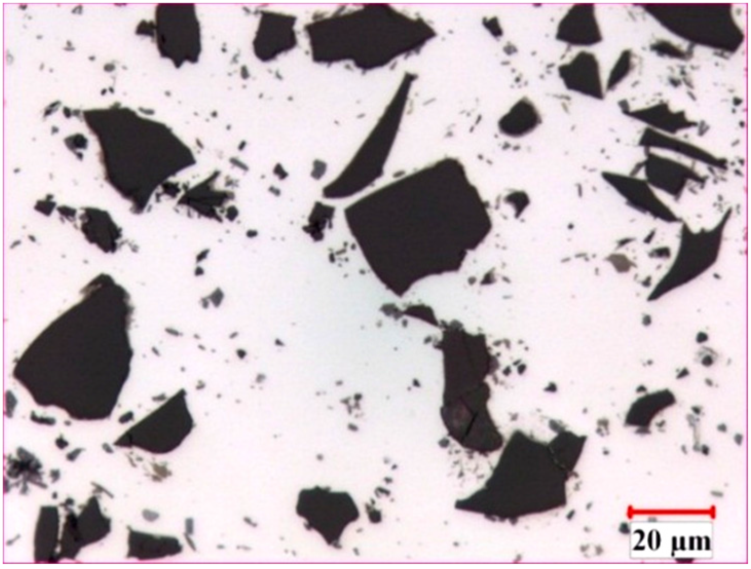
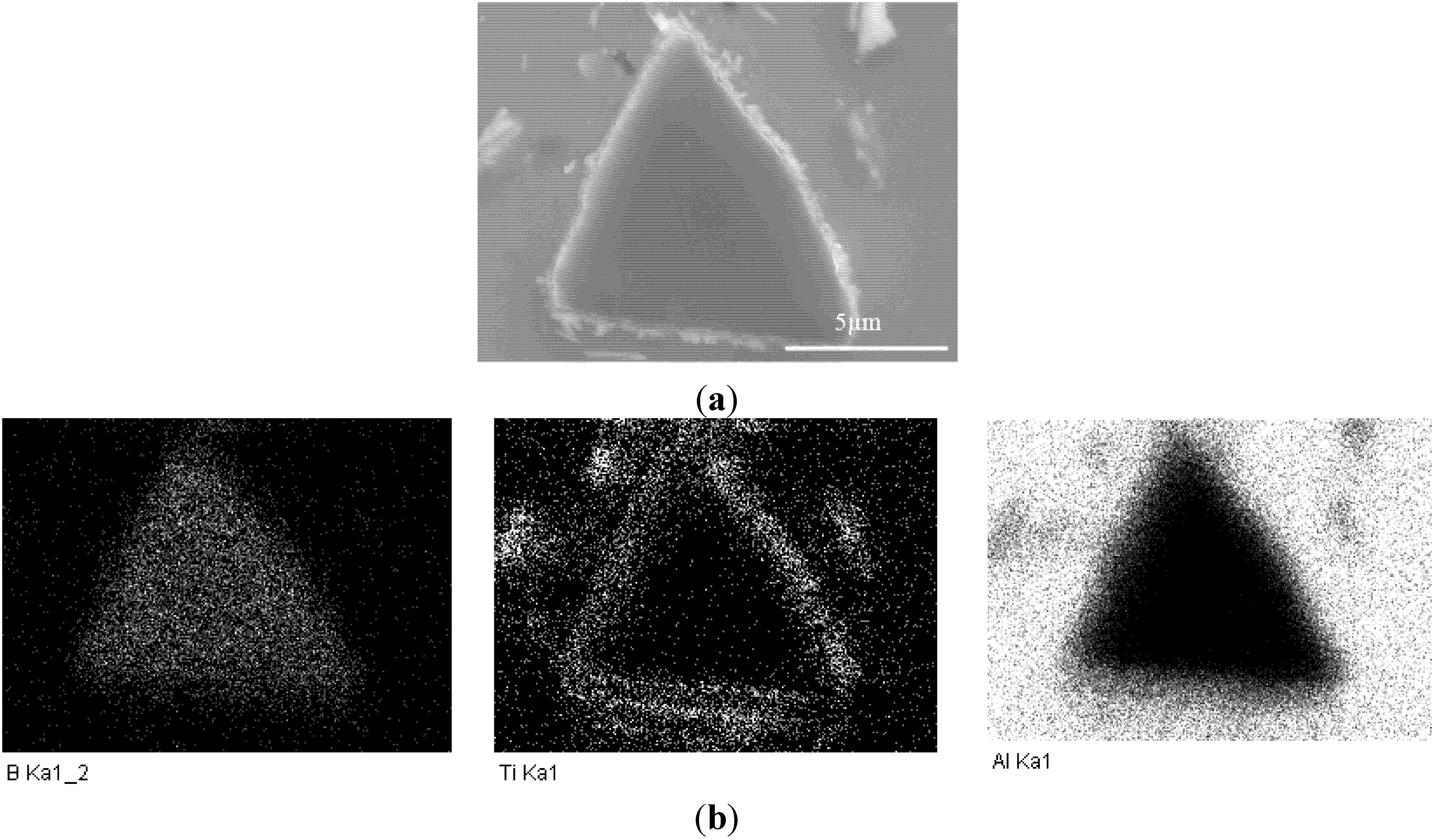
The microstructure of the AA1100-16 vol.% B4C composite is illustrated in Figure 1. In general, the B4C particles were distributed uniformly in the Al matrix, and two common reaction-induced intermetallic phases were observed in the composite and randomly dispersed in the Al matrix: AlB2 (brown, block-like phase) and Al3BC (grey phase) [32]. When fabricating the Al-B4C composites, the liquid aluminum reacted with B4C particles and produced AlB2 and Al3BC intermetallic particles [3,9]. To limit the reaction between the B4C particles and the liquid aluminum, 1.0~2.5 wt.% Ti was added to the composites. Afterward, a thin but dense TiB2 layer (a third reaction product) was formed in situ at the Al/B4C interfaces, isolating the B4C particles from the liquid aluminum [9,12]. Consequently, all B4C surfaces were surrounded with a TiB2 layer, as observed from the SEM micrographs and the X-ray elemental map in Figure 2. The microstructure of the AA1100-30 vol.% B4C composite was very similar to the AA1100-16 vol.% B4C composite, except for the increased B4C amount.
Figure 1.
Optical micrograph of hot-rolled AA1100-16 vol.% B4C composites.

Figure 2.
(a) SEM image of one B4C particle and (b) X-ray elemental mapping of (a) showing that B4C particles are protected by an in-situ TiB2 layer.
Figure 2.
(a) SEM image of one B4C particle and (b) X-ray elemental mapping of (a) showing that B4C particles are protected by an in-situ TiB2 layer.

3.2. Corrosion Behavior of Al-B4C Composites
3.2.1. Potentiodynamic Polarization
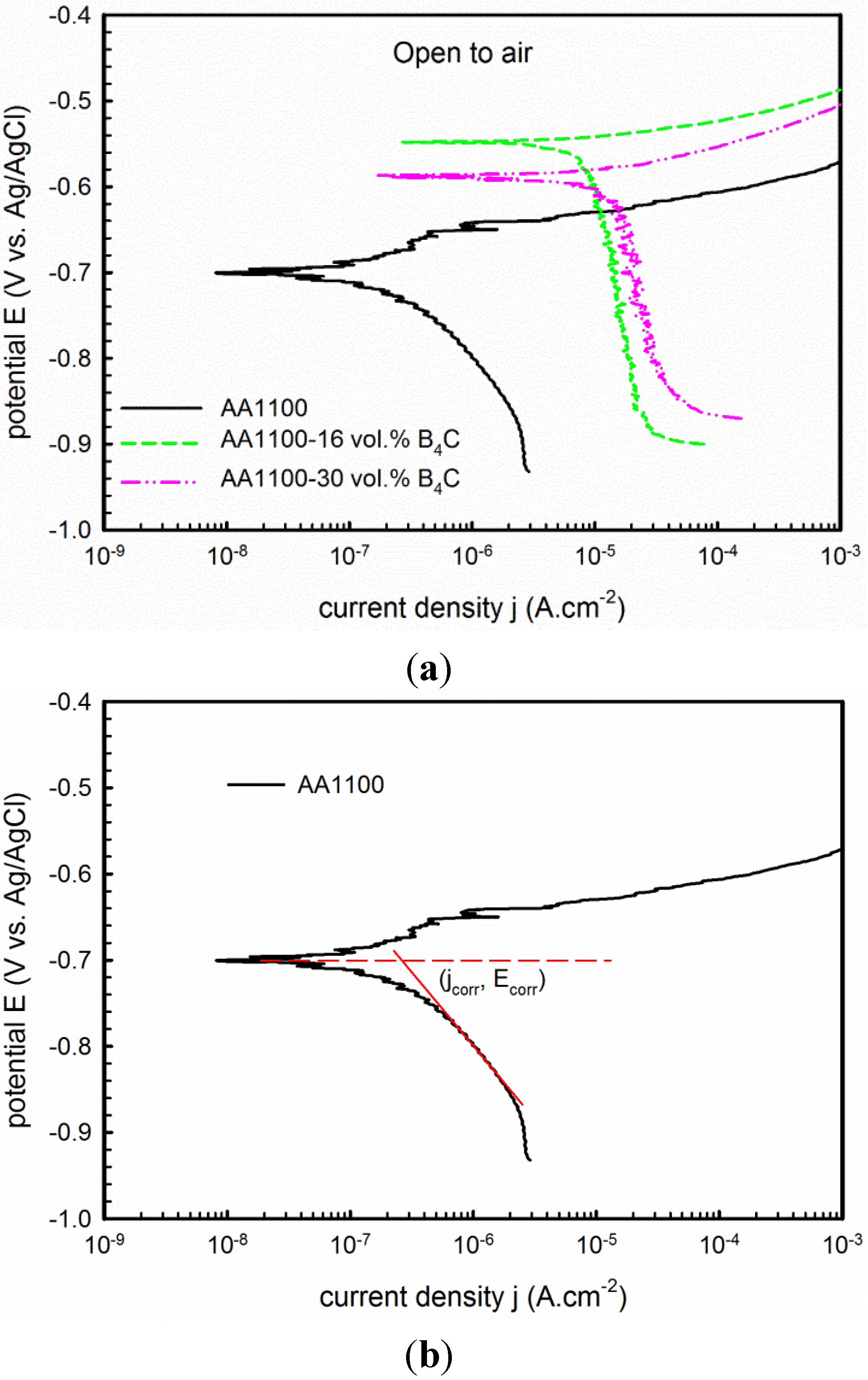
The electrochemical behavior of Al-B4C composite and effect of B4C particle content on corrosion were investigated using potentiodynamic polarization and electrochemical impedance spectroscopy (EIS). Figure 3a displays polarization curves of the composite with different B4C contents. The corrosion current density (jcorr) and corrosion potential (Ecorr) are obtained at the intersection point of extrapolation of the cathodic polarization branch and the Ecorr horizontal line, which is shown in the Figure 3b. As you will notice from Figure 3a, it is difficult to find a linear region near Ecorr on the anodic polarization branch of the AA1100 base alloy. Besides, the cathodic branch shows a long and defined linear behavior for over 100 mV; therefore, in this case, as suggested by McCafferty [33], the extrapolation of the cathodic branch method was used. All fittings were done at the liner part of cathodic branch for over 50 mV. The corrosion current density, corrosion potential and cathodic Tafel slopes values are summarized in Table 2.
It shows that the jcorr increases from 0.35 to 11.21 μA·cm−2 when B4C volume fraction increases from 0 to 30 vol.%, suggesting that the corrosion resistance of the composites decreases significantly when increasing the B4C volume fraction. The corrosion potential shifts in the positive direction, but the shift does not continue when increasing the B4C content. According to the mixed potential theory [28], the potential of the composite is expected to shift in the noble direction when increasing the B4C level in the composite. However, increasing the B4C volume fraction in the composite increases the discontinuity of the protective surface oxide films, making the Al-30 vol.% B4C composite more vulnerable to the chloride ions and generating a less noble potential.
Figure 3.
(a) Potentiodynamic polarization curve recorded on AA1100, AA1100-16 vol.% B4C and AA1100-30 vol.% B4C in 3.5 wt.% NaCl in open to air condition; (b) Plot showing the jcorr was obtained at the intersection point of extrapolation of the cathodic polarization branch and the Ecorr horizontal line.
| Materials | Open to Air | Argon Deaerated | ||||
|---|---|---|---|---|---|---|
| Ecorr (VAg/AgCl) | jcorr (μA·cm−2) | βc (V/decade) | Ecorr (VAg/AgCl) | jcorr (μA·cm−2) | bc (V/decade) | |
| AA1100 | −0.70 | 0.35 | 0.18 | −0.93 | 0.33 | 0.16 |
| AA1100-16 vol.% B4C | −0.55 | 8.39 | 0.71 | −0.94 | 0.99 | 0.14 |
| AA1100-30 vol.% B4C | −0.59 | 11.21 | 0.51 | −0.93 | 2.00 | 0.12 |
The anodic part of the polarization curve of the base alloy AA1100 reveals an oscillation region beyond which the current density increases quickly, indicating the onset of pitting corrosion. However, for the composite, jcorr increases steeply even under low overpotential, implying that pitting is more easily provoked in composites than in the base alloy.
3.2.2. Electrochemical Impedance Spectroscopy (EIS)
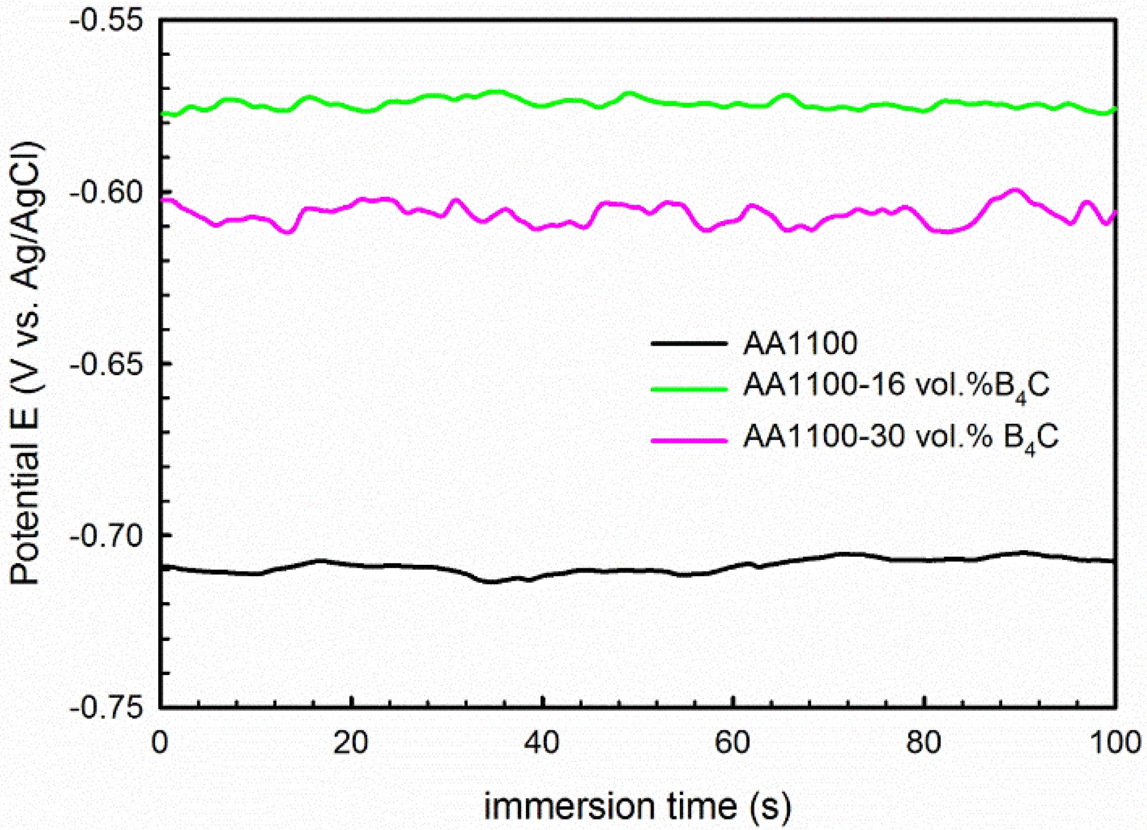
To further confirm the polarization results, EIS measurements were carried out for the composites and base alloy in 3.5 wt.% NaCl solution. Prior to the EIS measurement, the variation of Eocp as a function of time was measured and the graph is shown in Figure 4. It is observed that the Eocp is stabled at −710 ± 5 mV, −575 ± 3 mV and −607 ± 5 mV for AA1100, AA1100-16 vol.% B4C and AA1100-30 vol.% B4C, respectively.
Figure 4.
Eocp as a function of time measured 100 seconds before EIS tests, showing the Eocp of AA1100, AA1100-16 vol.% B4C and AA1100-30 vol.% B4C is stable before EIS tests.
Figure 4.
Eocp as a function of time measured 100 seconds before EIS tests, showing the Eocp of AA1100, AA1100-16 vol.% B4C and AA1100-30 vol.% B4C is stable before EIS tests.
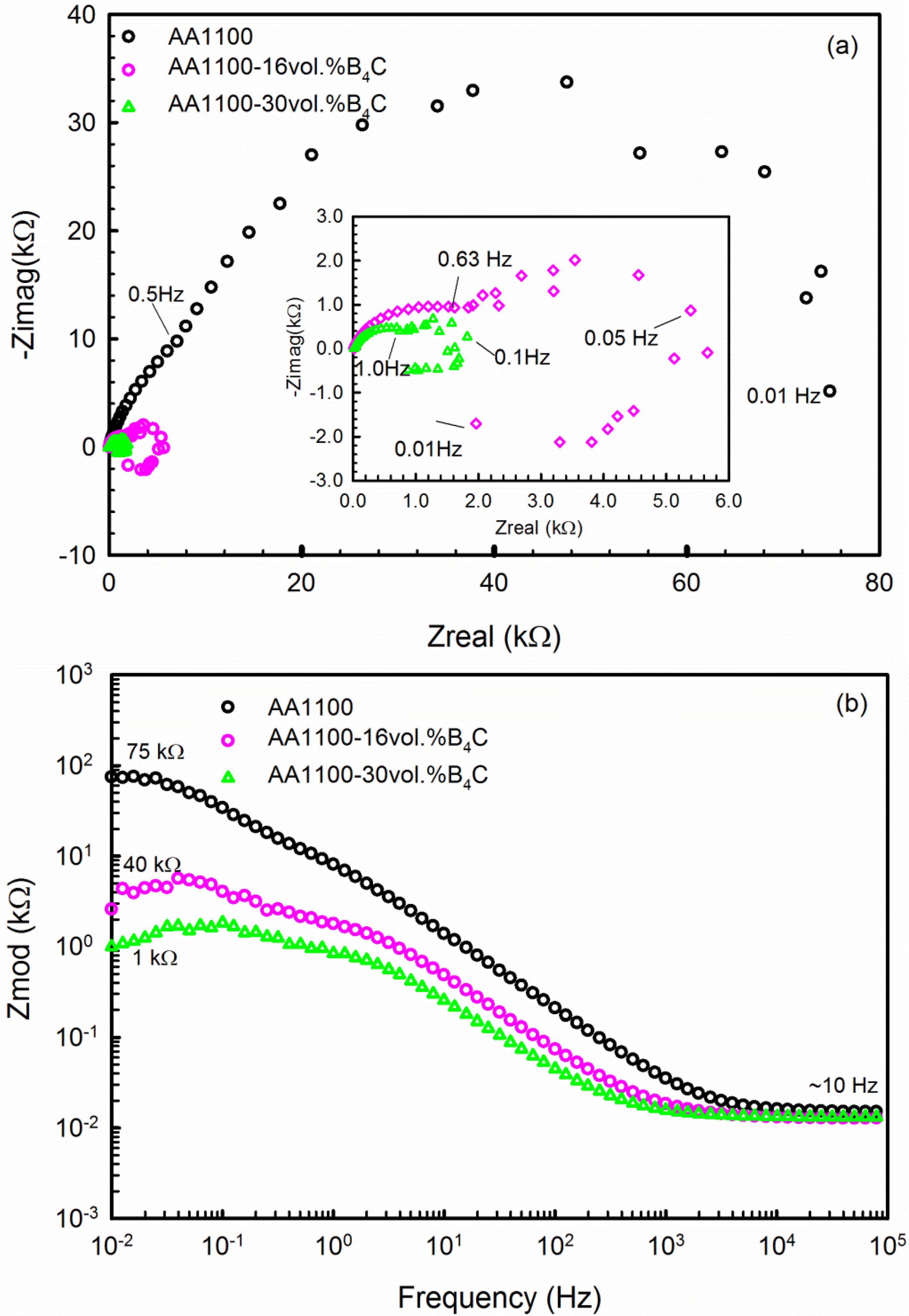
The impedance spectra obtained in complex impedance (Nyquist plot) and Bode impedance magnitude are displayed in Figure 5. The EIS spectra show a common characteristic: capacitive semicircles in the high and medium frequency range that are related to the aluminum oxide layer and the electrolyte [28]. The biggest HF semicircle is observed for the base alloy, and the diameter of semicircle decreases when increasing the B4C volume fraction in the composite. This observation confirms that incorporating B4C particles into AA6061 breaks the continuity of the oxide layer, decreasing its corrosion resistance. The base alloy also has an additional capacitive semicircle in the low frequency range that may be associated with the charge transfer across the alloy–electrolyte interface [34,35]. However, the Al-B4C composites show an inductive loop with a reduced charge transfer resistance at the low frequency range, revealing the occurrence of pitting on the composite surface.
The Bode impedance magnitude plot is displayed in Figure 5b. The impedance of the composite at the low frequency range decreases when increasing the B4C content. Because the material shows resistive behavior at low frequencies (0.01~0.1 Hz), the impedance at low frequencies could be considered as the resistance. The corrosion resistance of the composite decreases when increasing the B4C content, which validates the previous polarization results.
Similar EIS spectra were obtained for the B4C-reinforced AA6061 alloy in sea water; these data were interpreted using the equivalent circuits shown in Figure 6 [28]. In the first equivalent, Rs is the solution resistance, Rox is the aluminum oxide layer resistance and Rct is the charge-transfer resistance of the alloy. CPE1 is the capacitance between the electrolyte and the alloy, and CPE2 is the capacitance at the interface of the alloy and oxide layer. The equivalent circuit shown in Figure 7b is used to interpret the EIS spectra of the composites. In this equivalent circuit, there are two independent circuits. The first circuit corresponds to the HF capacitive loop that is described with CPE1 (double layer capacitance of the oxide layer–electrolyte interface) and Rox (charge-transfer resistance of the oxide layer). The second circuit represents the LF inductive loop; this circuit is described by RL (inductance resistance), L (inductance) and CPE2 (capacitance of pit–electrolyte interface).
Figure 5.
(a) Nyquist and (b) Bode plot of AA1100, AA1100-16 vol.% B4C and AA1100-30 vol.% B4C obtained after 1 h immersion in 3.5 wt.% NaCl solution.
Figure 5.
(a) Nyquist and (b) Bode plot of AA1100, AA1100-16 vol.% B4C and AA1100-30 vol.% B4C obtained after 1 h immersion in 3.5 wt.% NaCl solution.

Figure 6.
Equivalent circuits proposed for fitting EIS spectra obtained from (a) AA 1100 and (b) AA1100-16 vol.% B4C and AA1100-30 vol.% B4C in 3.5% NaCl solution.
Figure 6.
Equivalent circuits proposed for fitting EIS spectra obtained from (a) AA 1100 and (b) AA1100-16 vol.% B4C and AA1100-30 vol.% B4C in 3.5% NaCl solution.
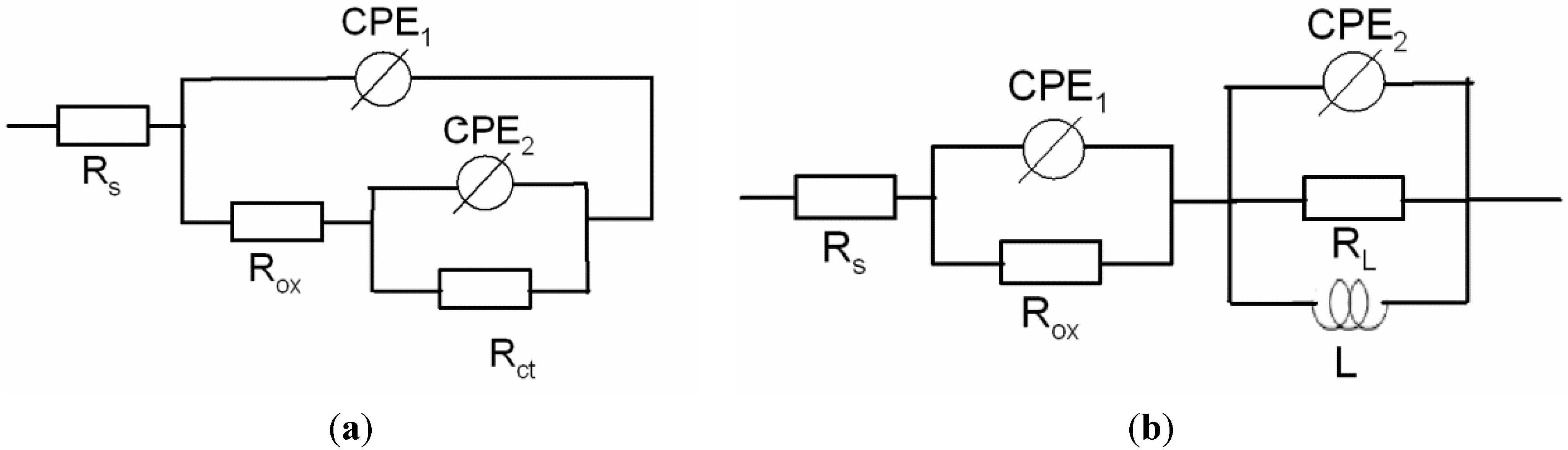
Figure 7.
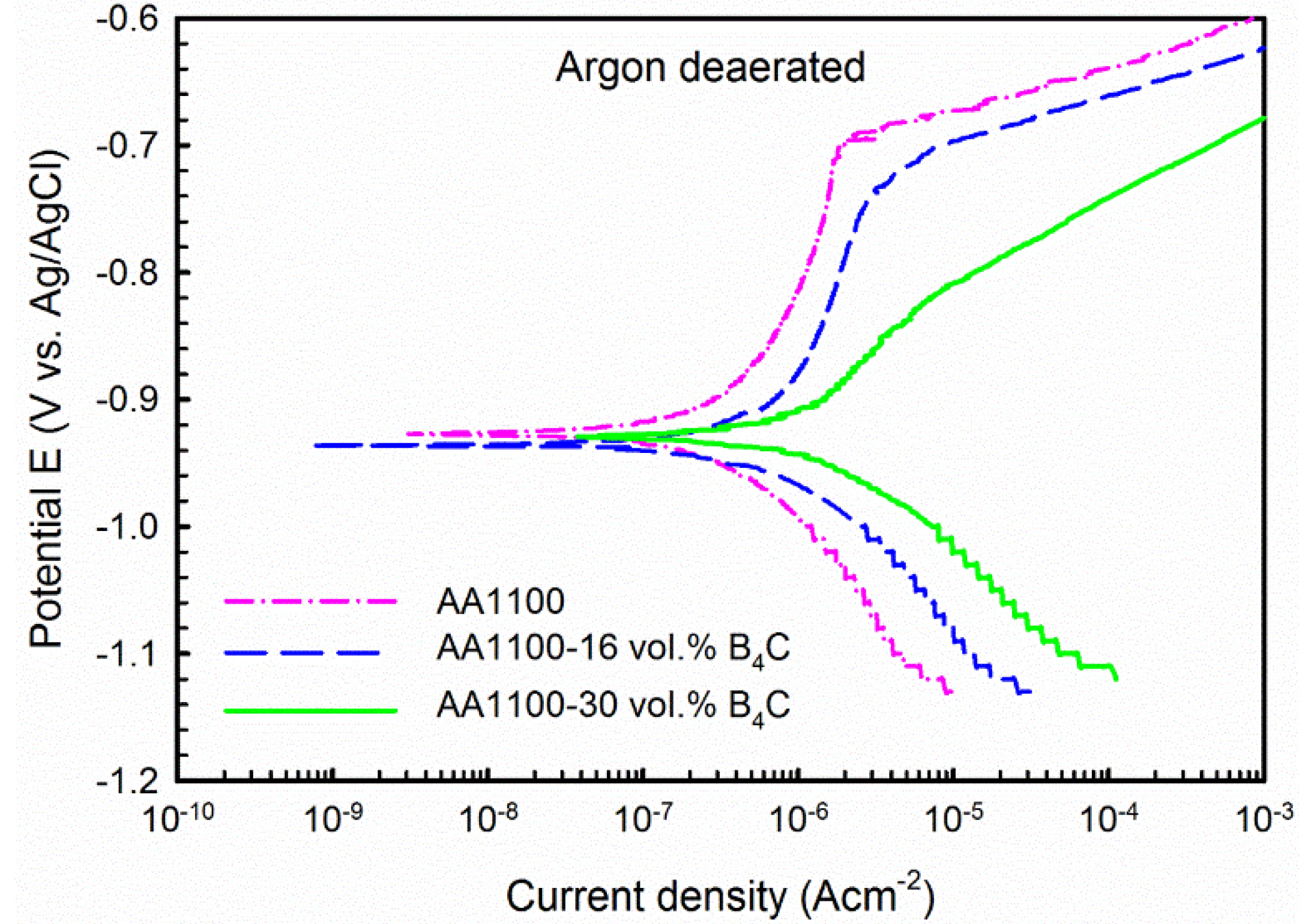
Potentiodynamic polarization curve recorded on AA1100, AA1100-16 vol.% B4C and AA1100-30 vol.% B4C in 3.5 wt.% NaCl in argon deaerated condition.
Figure 7.
Potentiodynamic polarization curve recorded on AA1100, AA1100-16 vol.% B4C and AA1100-30 vol.% B4C in 3.5 wt.% NaCl in argon deaerated condition.
Because the working electrode deviated from the ideal capacitive behavior due to its surface roughness, heterogeneities, anion adsorption, non-uniform potential, current profile, etc. [36], the constant phase element (CPE) was employed to substitute pure capacitances in the equivalent circuits employed.
All parameters derived from the equivalent circuits are summarized in Table 3. The oxide layer resistance Rox decreases from 23.74 to 0.89 kΩ·cm2, and the Rct or RL value decreases from 54.26 to 0.96 kΩ·cm2 when the B4C content increases from 0 to 30 vol.%. These results confirm the polarization results that the corrosion resistance of the composite decreases when increasing the B4C content.
Table 3.
Electrochemical parameters derived from the equivalent circuits in Figure 6.
| Materials | Rs (Ω cm2) | CPE1 (μF cm−2) | α1 | Rox (kΩ cm2) | CPE2 (μF cm−2) | α2 | Rct or RL (kΩ cm2) | L (H) |
|---|---|---|---|---|---|---|---|---|
| AA1100 | 14.79 | 20.83 | 0.85 | 23.74 | 30.93 | 0.96 | 54.26 | - |
| Al-16 vol.% B4C | 12.1 | 1.0 | 0.90 | 1.850 | 13.0 | 0.89 | 4.001 | 2200 |
| Al-30 vol.% B4C | 11.0 | 7.6 | 0.87 | 0.898 | 65.0 | 0.96 | 0.960 | 3200 |
3.3. Corrosion Mechanism Investigation
To study the corrosion mechanism of the composite, polarization tests were conducted in deaerated conditions. The polarization curves are shown in Figure 7 and derived parameters are listed in Table 2. Compared with polarization curves obtained in open-to-air condition, a passive region followed by a well-defined pitting potential at the current density approximately 1 μA·cm−2 is observed in the anodic branch for both the base alloy and the composites.
Besides, it is found that three materials have almost the same Ecorr, which means it does not vary with the B4C content as observed in open-to-air condition. However, it is more negative than that obtained in open-to-air condition for each material. As seen from Table 2, Ecorr decreased from −0.70 to −0.93 VAg/AgCl for the base alloy, from −0.55 to −0.92 VAg/AgCl for the composite with 16 vol.% B4C and from −0.59 to −0.93 VAg/AgCl for the composite with 30 vol.% B4C, respectively. More importantly, the corrosion current density jcorr is considerably lower than that obtained in open-to-air condition, i.e., jcorr is 0.99 μA·cm−2 for the composite with 16 vol.% B4C, and 2.00 μA·cm−2 for the composite with 30 vol.% B4C. This significant difference in current density shows that the corrosion kinetics of the base alloy (AA1100) and the Al-B4C composite in the NaCl solution are limited by the oxygen reduction reaction [33].
In addition, the difference on cathodic part of polarization curves was also observed. As seen from Figure 3, the current density remains constant or exhibits very small increases despite the potential increase of the cathodic branch in open-to-air condition. However, this observation was not found in deaerated condition. Similar behavior was observed by Singh et al. [30] for 2014-SiCp composites and by Dikici et al. [31] for SiO2 and Fe/TiO2 coated A380-SiC composites in aerated 3.5 wt.% NaCl solution. They believed that this electrochemical behavior is an indicator of the corrosion mechanism, which is controlled by oxygen diffusion.
3.4. Galvanic Current Measurement
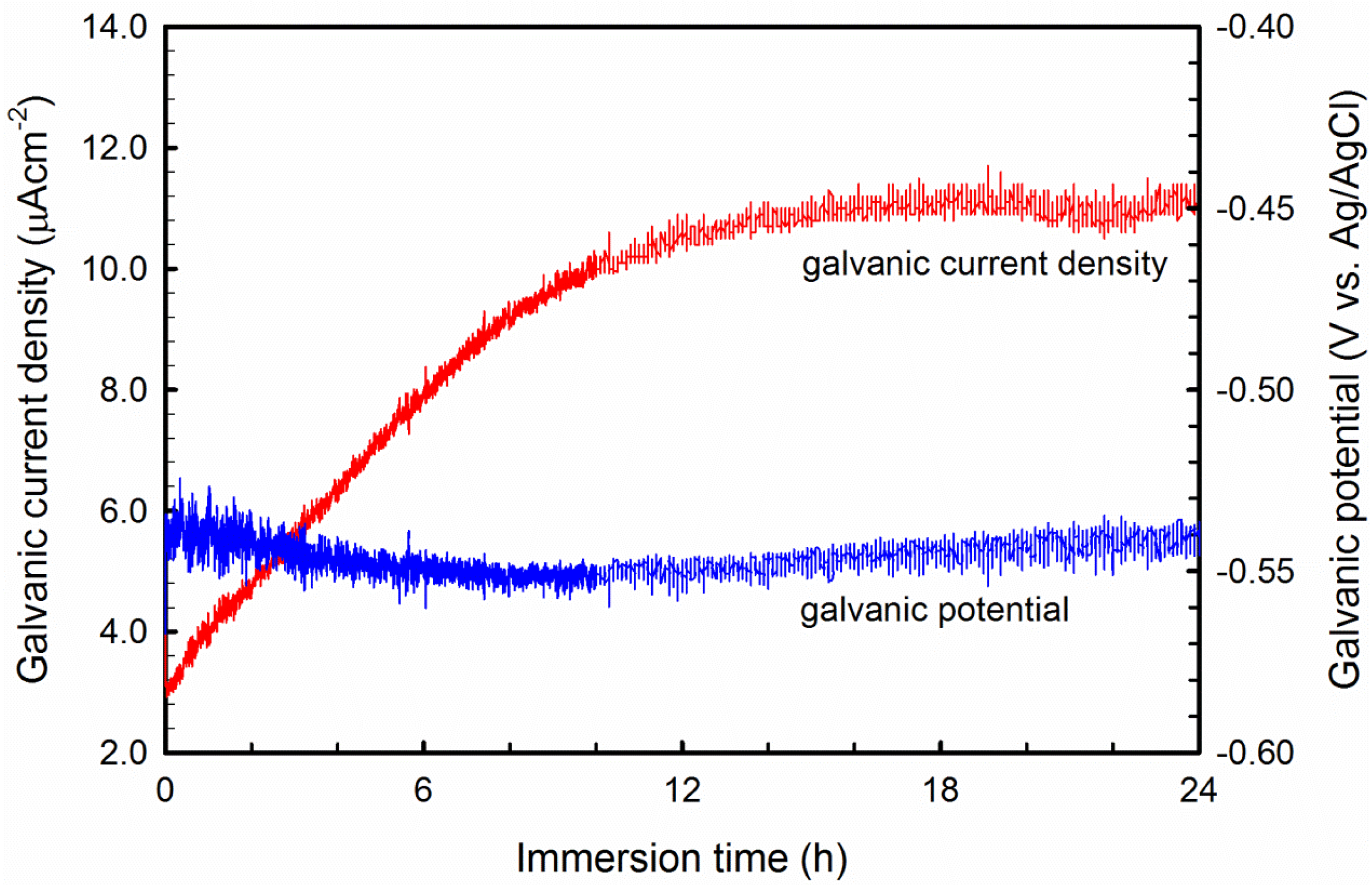
Because Al-B4C composites have junctions of two electrochemically dissimilar materials, galvanic corrosion between the Al alloy (matrix) and the reinforcing B4C particles may occur, degrading the corrosion resistance. As it is technically difficult to conduct a galvanic coupling test using small B4C particles, a hot-pressed 99.5% purity B4C wafer produced by Ceradyne, Inc. was used. During the galvanic corrosion test, the base alloy AA1100 was used as working electrode #1 (W1) and the B4C wafer was working electrode #2 (W2). A positive galvanic current means that working electrode #1 acts as an anode; otherwise, it acts as a cathode. The measured galvanic current and galvanic potential are shown in Figure 8. The galvanic current during the test is always positive, and the stable galvanic current is approximately 11.2 μA. This result suggests that the Al matrix and B4C particles in the composite can form galvanic couples in NaCl solution, and the Al matrix acts as an anode and dissolves. A similar result was obtained by Schneider et al. [37], when they studied the galvanic corrosion between pure Nickel and sintered SiC in 3.5 wt.% NaCl solution, i.e., SiC ceramic particles are cathodic sites of the coupling. Abenojar et al. [16] also found that the incorporated amorphous Fe/B particles act as cathode and form a strong galvanic couple with the aluminum matrix.
Figure 8.
Galvanic current and galvanic potential measured between AA1100 and B4C wafer in 3.5 wt.% NaCl solution.
Figure 8.
Galvanic current and galvanic potential measured between AA1100 and B4C wafer in 3.5 wt.% NaCl solution.
3.5. Pitting Morphology
To identify the initiation sites for the pitting, the AA1100-16 vol.% B4C composite sample was polished to 0.05 μm and polarized to 1 mA·cm−2. Figure 9 shows that pitting initiated at two sites: (1) the Al–B4C interfaces and (2) the sites away from the B4C particles in Al matrix where intermetallic phases appeared. Pits at the Al–B4C interfaces have an irregular shape, whereas pits in the Al matrix are generally large and hemispherical. Similar types of hemispherical pits were observed on AA5083 in aerated chloride solutions by Abelle et al. [38] and Katkar et al. [28]. They believed that these pits formed due to the simple detachment of the cathodic precipitates due to gravity. As mentioned in Section 3.1, many small intermetallic particles (AlB2 and Al3BC) were dispersed in the Al-B4C microstructure. Those intermetallic particles might be cathodic relative to the surrounding Al matrix. Due to the galvanic effect, the Al matrix around those intermetallic phases dissolves, detaching the particles.
Figure 9.
SEM images showing the pitting morphology and initiation places of the AA1100-16 vol.% B4C after being polarized to 1 mA·cm−2 in 3.5 wt.% NaCl solution: (a) at Al–B4C interfaces and (b) the Al matrix, where intermetallic phases appear.
Figure 9.
SEM images showing the pitting morphology and initiation places of the AA1100-16 vol.% B4C after being polarized to 1 mA·cm−2 in 3.5 wt.% NaCl solution: (a) at Al–B4C interfaces and (b) the Al matrix, where intermetallic phases appear.
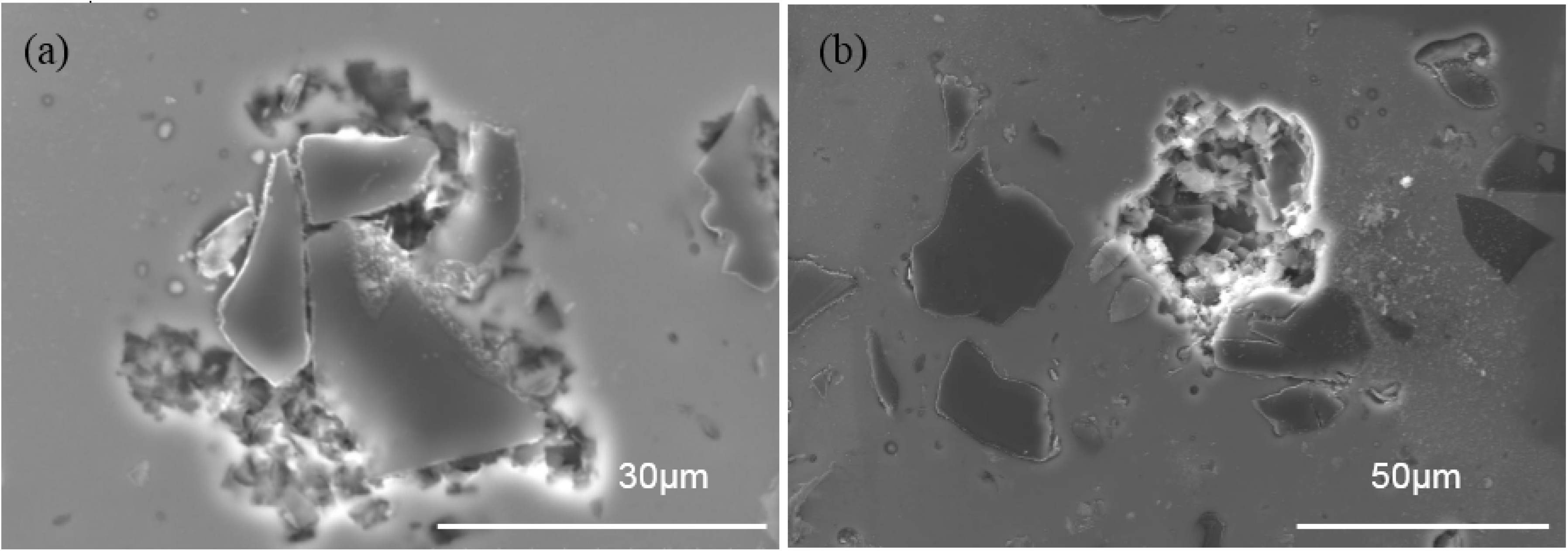
The formation of pits at the Al–B4C interfaces may occur for three reasons: (1) defects existing at the interface between aluminum and B4C where Cl− can easily penetrate and attack the Al matrix; (2) the protective TiB2 layer at Al/B4C interfaces that could be preferentially attacked by chloride ions [39]; (3) the galvanic coupling effect between the Al matrix and the B4C particles. Consequently, the Al matrix at the interfaces dissolves, and pits form around B4C particles. Once a pit is formed, the local chemical environment is substantially more aggressive than the bulk solution, and therefore the matrix is more severely corroded. Additionally, with increased B4C particles in the composite, the cathodic and anodic area ratio (AC/AA) increases due to the cathodic character of the B4C particles; a large AC/AA value is detrimental to the Al matrix. Hamdy et al. [40] confirmed the occurrence of galvanic and pitting attacks when they studied the corrosion resistance of ALCOA peak-aged AA6092-SiC17.5p composite in 3.5 wt.% NaCl.
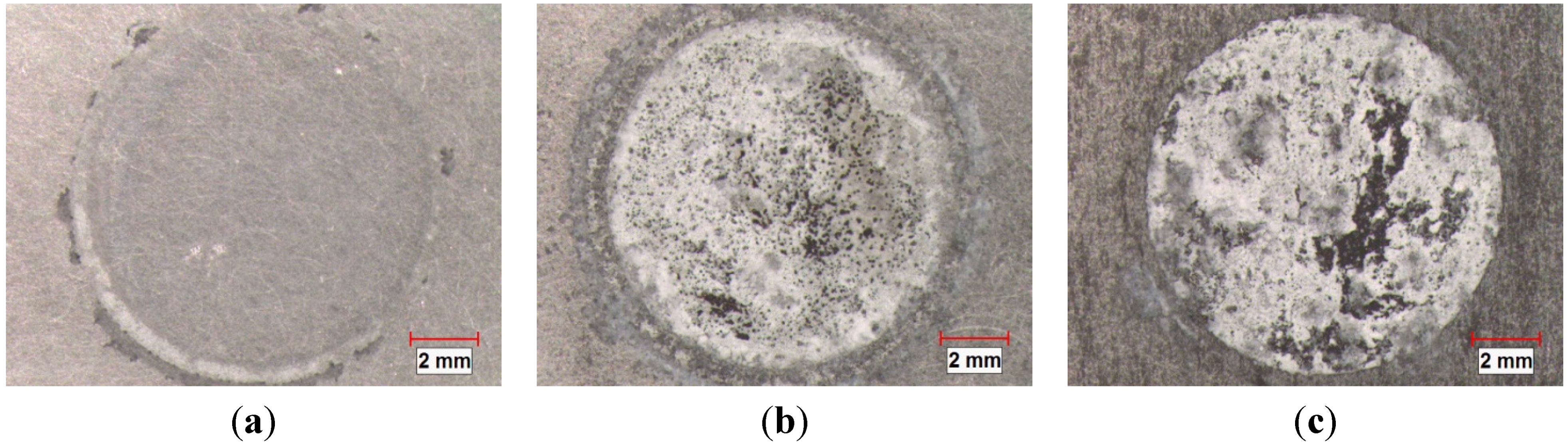
Figure 10 shows the surface appearance of the three materials (the base alloy, AA1100-16 vol.% B4C and AA1100-30 vol.% B4C) after immersion in 3.5 wt.% NaCl solution for 10 days. The corrosion degree of the test area increases when increasing the B4C volume fraction. To evaluate the corrosion of the materials with different B4C levels, cross sections from three samples are examined and displayed in Figure 11.
Figure 10.
Stereoscope graphs showing the corroded surface morphology of (a) AA1100; (b) AA1100-16 vol.% B4C and (c) AA1100-30 vol.% B4C immersed in 3.5 wt.% NaCl solution for 10 days.
Figure 10.
Stereoscope graphs showing the corroded surface morphology of (a) AA1100; (b) AA1100-16 vol.% B4C and (c) AA1100-30 vol.% B4C immersed in 3.5 wt.% NaCl solution for 10 days.
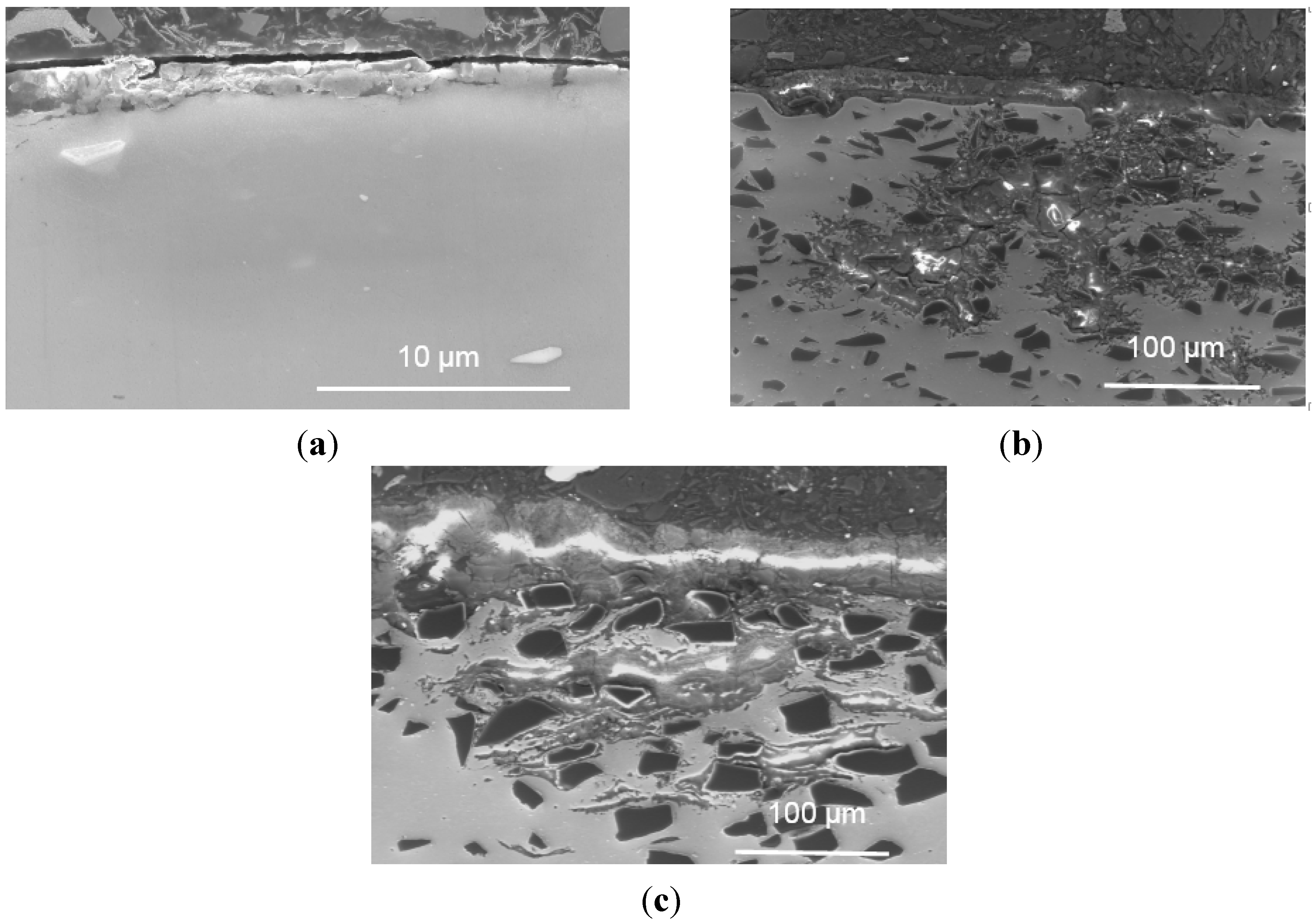
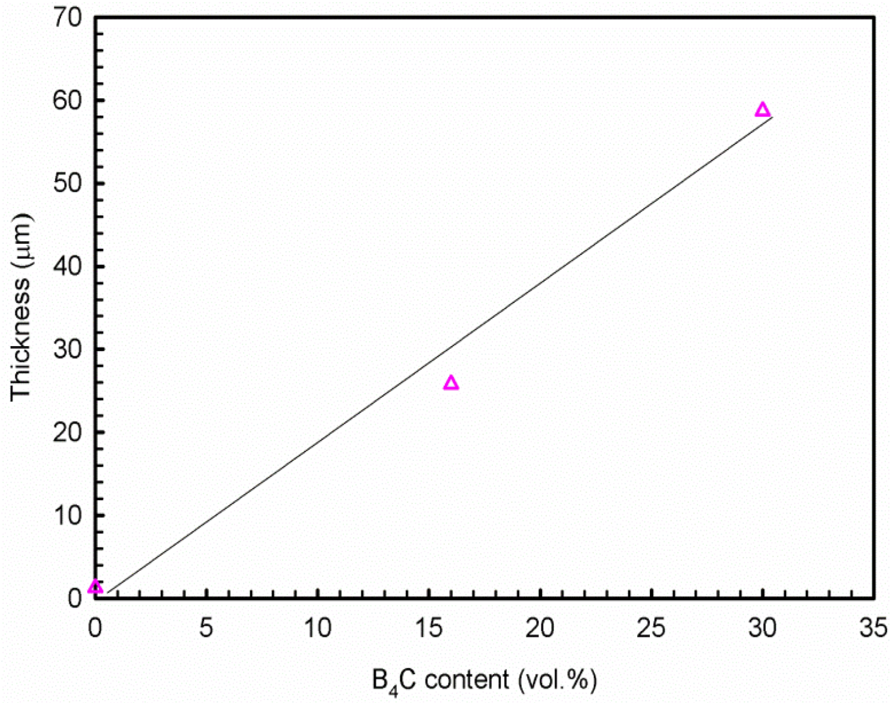
Uneven layers of corrosion products formed on the outermost surface of the base alloy and composites. The X-ray elemental maps revealed that these layers consist of aluminum oxide and/or hydroxides. The average corrosion product thickness (the corrosion products in the pits were not included in the calculation of the corroded layer thickness above) is obtained using 20 measurements collected from the SEM images and is presented in Figure 12. It is found that the thickness of the corroded layers increases linearly with the B4C content. The thickness of the corroded layer is approximately 1.3 μm in the base alloy and 25.8 μm in the AA1100-16 vol.% B4C composite, which is nearly 20 times that of the base alloy. When increasing the B4C content to 30 vol.%, the thickness reaches 58.7 μm, which is more than 40 times that of the base alloy. These observations indicate that adding B4C particles to the Al alloy can reduce the corrosion resistance in NaCl solution, which accords with the polarization and impedance measurements. Moreover, Figure 11 shows that only the composites suffer severe pitting, which confirms that the Al-B4C composite is more sensitive toward pitting than the base alloy in the NaCl solution.
Figure 11.
Cross-sectional morphology of (a) AA1100; (b) AA1100-16 vol.% B4C and (c) AA1100-30 vol.% B4C specimen immersed in 3.5 wt.% NaCl solution for 10 days.
Figure 11.
Cross-sectional morphology of (a) AA1100; (b) AA1100-16 vol.% B4C and (c) AA1100-30 vol.% B4C specimen immersed in 3.5 wt.% NaCl solution for 10 days.

Figure 12.
Relationship of corrosion product thickness and B4C volume fraction after 10 days exposure in 3.5 wt.% NaCl solution.
Figure 12.
Relationship of corrosion product thickness and B4C volume fraction after 10 days exposure in 3.5 wt.% NaCl solution.

4. Conclusions
- (1)
- The polarization and impedance results show that the Al-B4C composites are less corrosion-resistant than the base Al alloy and that the corrosion resistance of the composites decreases when increasing the B4C particle volume fraction. The cross-sectional images demonstrate that the thickness of corrosion products increases linearly with the B4C volume fraction.
- (2)
- Al-B4C composites are susceptible to pitting corrosion in the NaCl solution. Two types of pits are observed on the composite surface after polarization in the NaCl solution: (1) pits with an irregular shape that are preferentially initiated at Al/B4C interfaces and (2) hemispheric pits that initiate in the Al matrix where the intermetallic particles appeared.
- (3)
- The corrosion of Al-B4C composites in 3.5 wt.% NaCl solution is mainly controlled by oxygen reduction in the solution. Moreover, the galvanic couples formed between B4C particles and Al matrix is also responsible for the low corrosion resistance.
Acknowledgments
The authors are grateful for the financial support from the Natural Sciences and Engineering Research Council of Canada (NSERC), from Rio Tinto Alcan and from the NRC-Aluminium Technology Centre through the NSERC Industrial Research Chair in Metallurgy of Aluminium Transformation at the University of Quebec in Chicoutimi. The authors also wish to thank D. Gallant for his kind guidance, as well as H. Grégoire, A. Ruest, G. Simard and M. Côté of the NRC-Aluminium Technology Centre for their technical assistance.
Author Contributions
Yu-Mei Han designed and conducted the whole experiment, interpreted all data and prepared the manuscript, X.-Grant Chen supervised the research work.
Conflicts of Interest
The authors declare no conflict of interest.
References
- Pardo, A.; Merino, M.C.; Merino, S.; Viejo, F.; Carboneras, M.; Arrabal, R. Influence of reinforcement proportion and matrix composition on pitting corrosion behaviour of cast aluminium matrix composites (A3xx.x/SiCp). Corros. Sci. 2005, 47, 1750–1764. [Google Scholar] [CrossRef]
- Miracle, D.B. Metal matrix composites—From science to technological significance. Compos. Sci. Technol. 2005, 65, 2526–2540. [Google Scholar] [CrossRef]
- Chen, X.-G. Application of Al-B4C Metal Matrix Composites in the Nuclear Industry for Neutron Absorber Materials. In Proceedings of the Symposium on Solidification Processing of Metal Matrix Composites, San Antonio, TX, USA, 12–26 March 2006.
- Mohanty, R.M.; Balasubramanian, K.; Seshadri, S.K. Boron carbide-reinforced alumnium 1100 matrix composites: Fabrication and properties. Mater. Sci. Eng. A 2008, 498, 42–52. [Google Scholar] [CrossRef]
- Hemanth, J. Tribological behavior of cryogenically treated B4Cp/Al-12% Si composites. Wear 2005, 258, 1732–1744. [Google Scholar] [CrossRef]
- Thévenot, F. Boron carbide—A comprehensive review. J. Eur. Ceram. Soc. 1990, 6, 205–225. [Google Scholar] [CrossRef]
- Lillo, T.M. Enhancing ductility of AL6061 + 10 wt.% B4C through equal-channel angular extrusion processing. Mater. Sci. Eng. A 2005, 410–411, 443–446. [Google Scholar]
- Abenojar, J.; Velasco, F.; Martínez, M.A. Optimization of processing parameters for the Al + 10% B4C system obtained by mechanical alloying. J. Mater. Process. Technol. 2007, 184, 441–446. [Google Scholar] [CrossRef]
- Kennedy, A.R. The microstructure and mechanical properties of Al-Si-B4C metal matrix composites. J. Mater. Sci. 2002, 37, 317–323. [Google Scholar] [CrossRef]
- Canakci, A.; Arslan, F.; Varol, T. Effect of volume fraction and size of B4C particles on production and microstructure properties of B4C reinforced aluminium alloy composites. Mater. Sci. Technol. 2013, 29, 954–960. [Google Scholar] [CrossRef]
- Abenojar, J.; Martinez, M.A.; Velasco, F. Effect of the boron content in the aluminium/boron composite. J. Alloys Compd. 2006, 422, 67–72. [Google Scholar] [CrossRef]
- Chen, X.-G.; Hark, R. Development of Al-30%B4C Metal Matrix Composites for Neutron Absorber Material. In Proceedings of the Aluminium Alloys: Fabrication, Characerization and Applications, New Orleans, LA, USA, 13–19 March 2008.
- Bonnet, G.; Rohr, V.; Chen, X.G.; Bernier, J.L.; Chiocca, R.; Issard, H. Use of alcan’s Al-B4C metal matrix composites as neutron absorber material in TN international’s transportation and storage casks. Packag. Transp. Storage Secur. Radioact. Mater. 2009, 20, 98–102. [Google Scholar] [CrossRef]
- Han, Y.-M.; Gallant, D.; Chen, X.G. Galvanic corrosion associated with Al-B4C composites/SS304 and Al-B4C composites/AA6061 couples in NaCl and H3BO3 solutions. Electrochim. Acta 2013, 94, 134–142. [Google Scholar] [CrossRef]
- Han, Y.-M.; Gallant, D.; Chen, X.G. Corrosion inhibition of Al-B4C metal matrix composites in a NaCl solution by benzotriazole. Mater. Chem. Phys. 2013, 139, 187–195. [Google Scholar] [CrossRef]
- Abenojar, J.; Bautista, A.; Guzmán, S.; Velasco, F. Microstructural influence on corrosion properties of aluminium composites reinforced with amorphous iron borides. Mater. Corros. 2014, 65, 678–684. [Google Scholar] [CrossRef]
- Abenojar, J.; Bautista, A.; Guzmán, S.; Velasco, F.; Martinez, M.A. Study through potentiodynamic techniques of the corrosion resistance of different aluminium base MMC’s with boron additions. Mater. Sci. Forum 2010, 660–661, 203–208. [Google Scholar] [CrossRef]
- Reena Kumari, P.D.; Nayak, J.; Shetty, A.N. Corrosion behavior of 6061/Al-15 vol. pct. SiC (p) composite and the base alloy in sodium hydroxide solution. Arabian J. Chem. 2011. [Google Scholar] [CrossRef]
- Zakaria, H.M. Microstructural and corrosion behavior of Al/SiC metal matrix composites. Ain Shams Eng. J. 2014, 5, 831–838. [Google Scholar] [CrossRef]
- Trowsdale, A.J.; Noble, B.; Harris, S.J.; Gibbins, I.S.R.; Thompson, G.E.; Wood, G.C. The influence of silicon carbide reinforcement on the pitting behaviour of aluminium. Corros. Sci. 1996, 38, 177–191. [Google Scholar] [CrossRef]
- Aziz, I.; Qi, Z.; Min, X. Corrosion inhibition of SiCp/5A06 aluminum metal matrix composite by cerium conversion treatment. Chin. J. Aeronaut. 2009, 22, 670–676. [Google Scholar] [CrossRef]
- Singh, I.B.; Mandal, D.P.; Singh, M.; Das, S. Influence of SiC particles addition on the corrosion behavior of 2014 Al-Cu alloy in 3.5% NaCl solution. Corros. Sci. 2009, 51, 234–241. [Google Scholar] [CrossRef]
- Zhu, J.; Hihara, L.H. Corrosion of continuous alumina-fibre reinforced Al-2 wt.% Cu-T6 metal-matrix composite in 3.15 wt.% NaCl solution. Corros. Sci. 2010, 52, 406–415. [Google Scholar] [CrossRef]
- Bhat, M.S.N.; Surappa, M.K.; Nayak, H.V.S. Corrosion behaviour of silicon carbide particle reinforced 6061/Al alloy composites. J. Mater. Sci. 1991, 26, 4991–4996. [Google Scholar] [CrossRef]
- Sun, H.; Koo, E.Y.; Wheat, H.G. Corrosion behavior of SiCp/6061 Al metal matrix composites. Corrosion 1991, 47, 741–753. [Google Scholar] [CrossRef]
- Roepstorff, S.; Maahn, E. Corrosion Resistance of Aluminum-Silicon Carbide Composite Materials. In Proceeding of the 12th Scandinavian Corrosion Congress and Eurocorr’92, Espoo, Finland, 31 May–4 June 1992.
- Ding, H.; Hihara, L. Localized corrosion currents and pH profile over B4C, SiC, and Al2O3 reinforced 6092 aluminum composites: I. in 0.5 M Na2SO4 solution. J. Electrochem. Soc. 2005, 152, B161–B167. [Google Scholar] [CrossRef]
- Katkar, V.A.; Gunasekaran, G.; Rao, A.G.; Koli, P.M. Effect of the reinforced boron carbide particulate content of AA6061 alloy on formation of the passive film in seawater. Corros. Sci. 2011, 53, 2700–2712. [Google Scholar] [CrossRef]
- Han, Y.; Gallant, D.; Chen, X.-G. Corrosion Behavior of Al-B4C Metal Matrix Composites in H3BO3, K2SO4 and NaCl Solutions. In Light Metal; MetSoc: Montreal, QC, Canada, 2011. [Google Scholar]
- Han, Y.; Gallant, D.; Chen, X.-G. Investigation on corrosion behavior of the Al-B4C metal matrix composite in a mildly oxidizing aqueous environment. Corrosion 2011, 67. [Google Scholar] [CrossRef]
- Zhang, Z.; Fortin, K.; Charette, A. Effect of titanium on microstructure and fluidity of Al-B4C composites. J. Mater. Sci. 2011, 46, 3176–3185. [Google Scholar] [CrossRef]
- Viala, J.C.; Bouix, J.; Gonzalez, G.; Esnouf, C. Chemical reactivity of aluminium with boron carbide. J. Mater. Sci. 1997, 32, 4559–4573. [Google Scholar] [CrossRef]
- McCafferty, E. Validation of corrosion rates measured by the Tafel extrapolation method. Corros. Sci. 2005, 47, 3202–3215. [Google Scholar] [CrossRef]
- Gamry Instrument. Basics of Electrochemical Impedance Spectroscopy; Gamry Instrument: Warminster, PA, USA, 2007. [Google Scholar]
- Mansfeld, F. An Introduction to Electrochemical Impedance Measurement. In Technique Report; Solartron Ltd.: Shildon, UK, 1999. [Google Scholar]
- Jorcin, J.-B.; Orazem, M.E.; Pébère, N.; Tribollet, B. CPE analysis by local electrochemical impedance spectroscopy. Electrochim. Acta 2006, 51, 1473–1479. [Google Scholar] [CrossRef] [Green Version]
- Schneider, M.; Kremmer, K.; Lämmel, C.; Sempf, K.; Herrmann, M. Galvanic corrosion of metal/ceramic coupling. Corros. Sci. 2014, 80, 191–196. [Google Scholar] [CrossRef]
- Aballe, A.; Bethencourt, M.; Botana, F.J.; Cano, M.J.; Marcos, M. Influence of the cathodic intermetallics distribution on the reproducibility of the electrochemical measurements on AA5083 alloy in NaCl solutions. Corros. Sci. 2003, 45, 161–180. [Google Scholar]
- Monticelli, C.; Frignani, A.; Bellosi, A.; Brunoro, G.; Trabanelli, G. The corrosion behaviour of titanium diboride in neutral chloride solution. Corros. Sci. 2001, 43, 979–992. [Google Scholar] [CrossRef]
- Hamdy, A.S.; Alfosail, F.; Gasem, Z. Electrochemical behavior of a discontinuously A6092/SiC/17.5p metal matrix composite in chloride containing solution. Electrochim. Acta 2013, 88, 129–134. [Google Scholar]
© 2015 by the authors; licensee MDPI, Basel, Switzerland. This article is an open access article distributed under the terms and conditions of the Creative Commons Attribution license (http://creativecommons.org/licenses/by/4.0/).
Share and Cite
MDPI and ACS Style
Han, Y.-M.; Chen, X.-G. Electrochemical Behavior of Al-B4C Metal Matrix Composites in NaCl Solution. Materials 2015, 8, 6455-6470. https://doi.org/10.3390/ma8095314
AMA Style
Han Y-M, Chen X-G. Electrochemical Behavior of Al-B4C Metal Matrix Composites in NaCl Solution. Materials. 2015; 8(9):6455-6470. https://doi.org/10.3390/ma8095314
Chicago/Turabian StyleHan, Yu-Mei, and X.-Grant Chen. 2015. "Electrochemical Behavior of Al-B4C Metal Matrix Composites in NaCl Solution" Materials 8, no. 9: 6455-6470. https://doi.org/10.3390/ma8095314