
Physical Characteristics of Medical Textile Prostheses Designed for Hernia Repair: A Comprehensive Analysis of Select Commercial Devices

Abstract
:
1. Introduction
2. Results
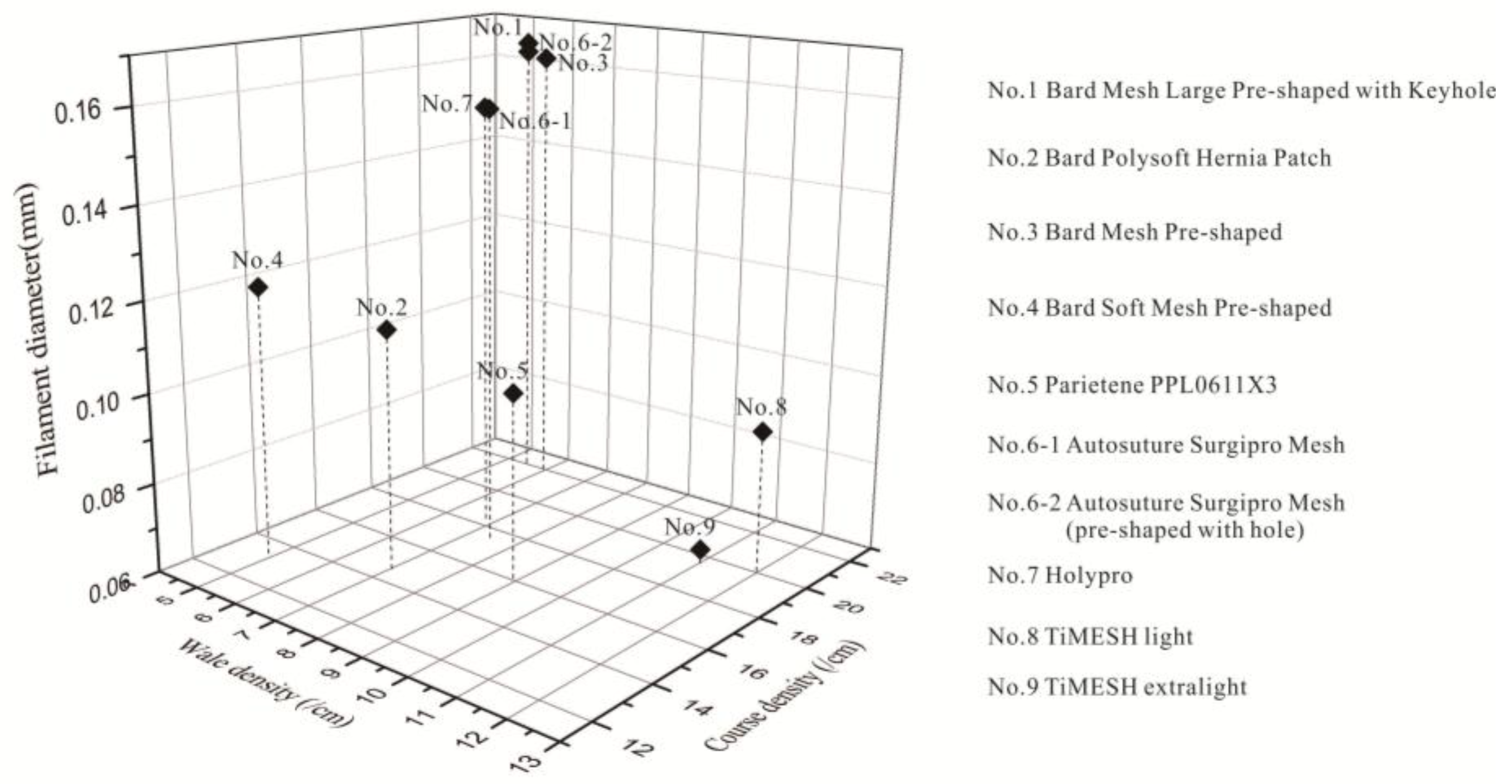
2.1. Textile Structure Characteristics

| Device No. | Filament Diameter (mm) | Filament Linear Density (Tex) | Stitch Density(cm) | Thickness (mm) | Weight (g/m2) | Porosity (%) Area Method | Porosity (%) Weight Method | |
|---|---|---|---|---|---|---|---|---|
| Wales | Courses | |||||||
| 1 | 0.165 ± 0.005 | 19.25 | 5.5 ± 0.0 | 22.0 ± 0.3 | 0.71 ± 0.01 | 97.0 ± 0.0 | 41.6 ± 1.1 | 84.7 ± 0.0 |
| 2 | 0.114 ± 0.004 | 9.19 | 7.1 ± 0.1 | 14.5 ± 0.2 | 0.36 ± 0.01 | – | 62.4 ± 1.3 | – |
| 3 | 0.162 ± 0.002 | 18.55 | 6.0 ± 0.0 | 21.9 ± 0.2 | 0.66 ± 0.01 | 99.8 ± 2.0 | 40.1 ± 1.0 | 83.2 ± 0.3 |
| 4 | 0.121 ± 0.013 | 10.35 | 5.0 ± 0.0 | 13.2 ± 0.0 | 0.43 ± 0.03 | 40.1 ± 0.1 | 64.8 ± 0.8 | 89.6 ± 0.0 |
| 5 | 0.102 ± 0.001 | 7.36 | 9.0 ± 0.0 | 15.9 ± 0.1 | 0.35 ± 0.01 | 35.9 ± 0.0 | 57.7 ± 0.6 | 88.7 ± 0.0 |
| 6-1 | 0.157 ± 0.006 | 17.52 | 7.5 ± 0.1 | 17.4 ± 0.1 | 0.60 ± 0.01 | 90.3 ± 0.1 | 44.8 ± 1.1 | 83.3 ± 0.0 |
| 6-2 | 0.163 ± 0.005 | 18.73 | 5.5 ± 0.0 | 22.0 ± 0.2 | 0.68 ± 0.01 | 90.9 ± 0.1 | 41.5 ± 0.5 | 85.2 ± 0.0 |
| 7 | 0.156 ± 0.002 | 17.20 | 7.0 ± 0.1 | 18.0 ± 0.3 | 0.57 ± 0.02 | 97.2 ± 4.6 | 37.3 ± 1.1 | 81.1 ± 1.0 |
| 8 | 0.092 ± 0.005 | 5.98 | 12.0 ± 0.0 | 20.0 ± 0.1 | 0.29 ± 0.00 | 35.0 * | 60.4 ± 0.7 | – |
| 9 | 0.065 ± 0.001 | 2.95 | 11.2 ± 0.1 | 19.2 ± 0.1 | 0.22 ± 0.00 | 16.0 * | 69.7 ± 0.6 | – |
2.1.1. Filament Diameter
2.1.2. Linear Density
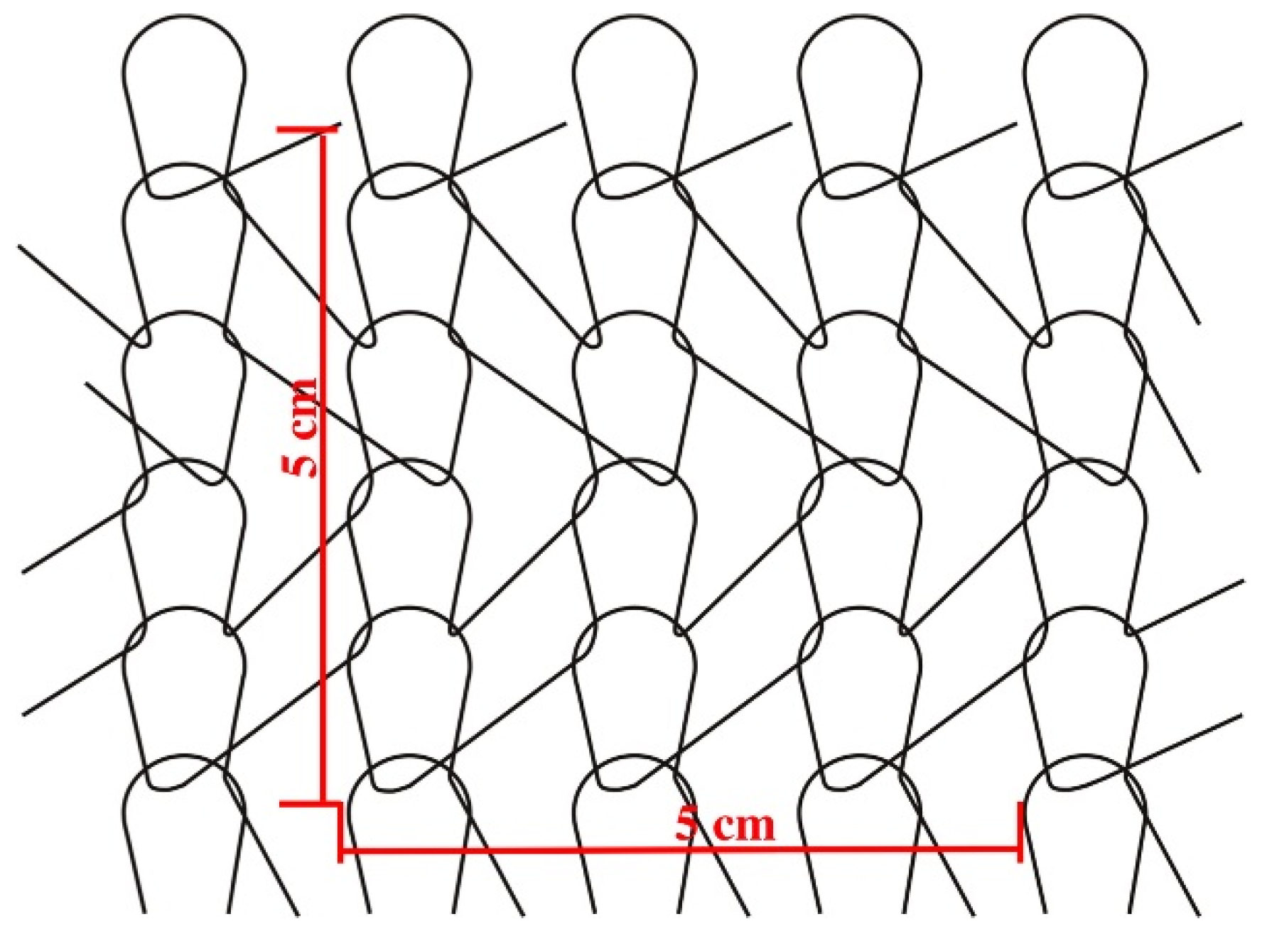
2.1.3. Stitch Density
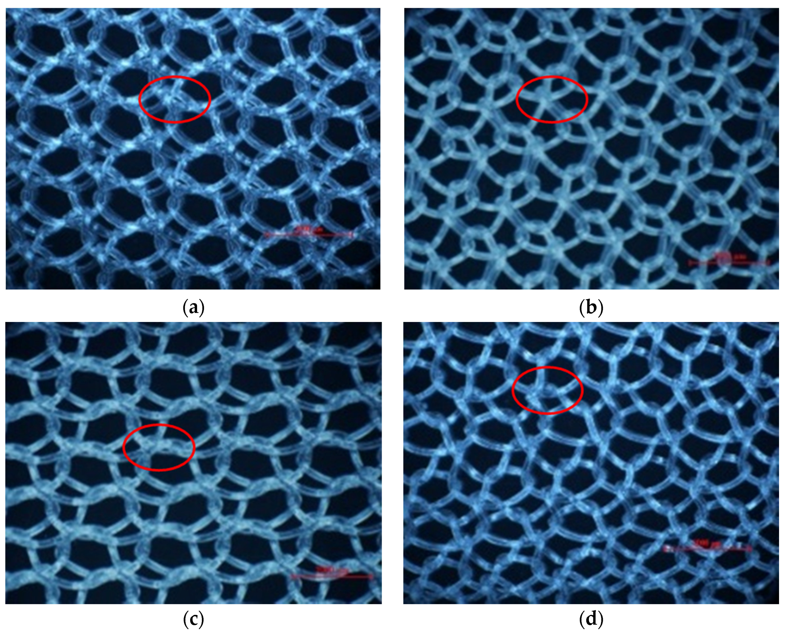
2.1.4. Loop Structures and Knitting-Lapping Diagrams
| Device No. | Structure | Light Microscopy (20×) | Knitting-Lapping Diagram | Chain Notation |
|---|---|---|---|---|
| 1 | single-guide bar; open-lap three-needle atlas | 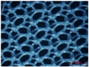 |  | 1-0/1-2/2-3/2-1// |
| 2 | single-guide bar; closed-lap three-needle atlas | 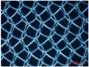 |  | 1-0/2-1/2-3/1-2// |
| 3 | single-guide bar; open-lap three-needle atlas | 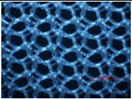 | | 1-0/1-2/2-3/2-1// |
| 4 | two-guide bars; modified tricot | 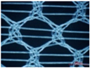 | 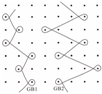 | GB1:2-3/2-1/2-3/1-0/1-2/1-0// GB2:2-1/4-3/2-1/3-4/1-0/2-1// |
| 5 | two-guide bars; combined atlas and tricot lapping | 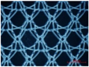 |  | GB1:3-4/5-4/4-3/2-1/0-1/1-2// GB2:2-1/0-1/1-2/3-4/5-4/4-3// |
| 6-1 | single-guide bar; open-lap three-needle atlas | 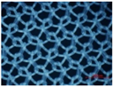 | | 1-0/1-2/2-3/2-1// |
| 6-2 | single-guide bar; open-lap three-needle atlas |  | | 1-0/1-2/2-3/2-1// |
| 7 | single guide bar; open-lap three-needle atlas | 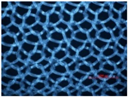 | | 1-0/1-2/2-3/2-1// |
| 8 | two-guide bars; open-lap three-needle atlas |  |  | GB1:1-0/1-2/2-3/2-1// GB2:2-3/2-1/1-0/1-2// |
| 9 | two-guide bars; open-lap three-needle atlas | 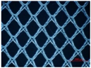 | | GB1:1-0/1-2/2-3/2-1// GB2:2-3/2-1/1-0/1-2// |


2.2. General Physical Properties
2.2.1. Thickness
2.2.2. Density
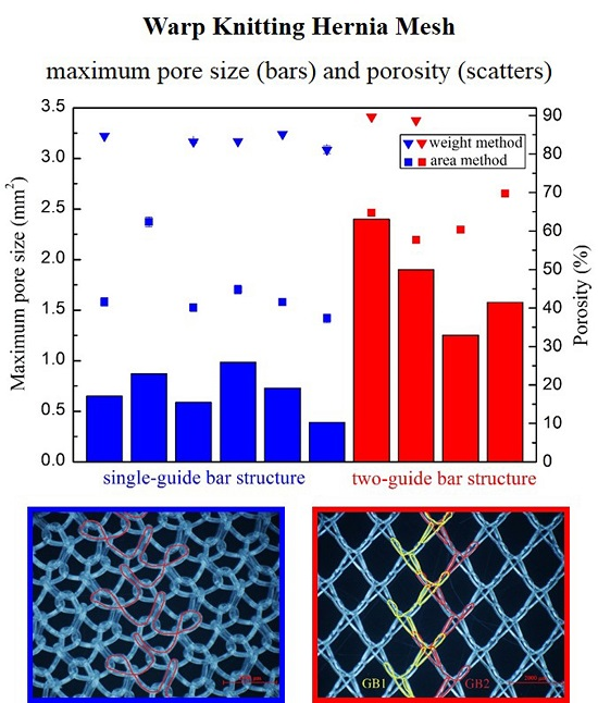
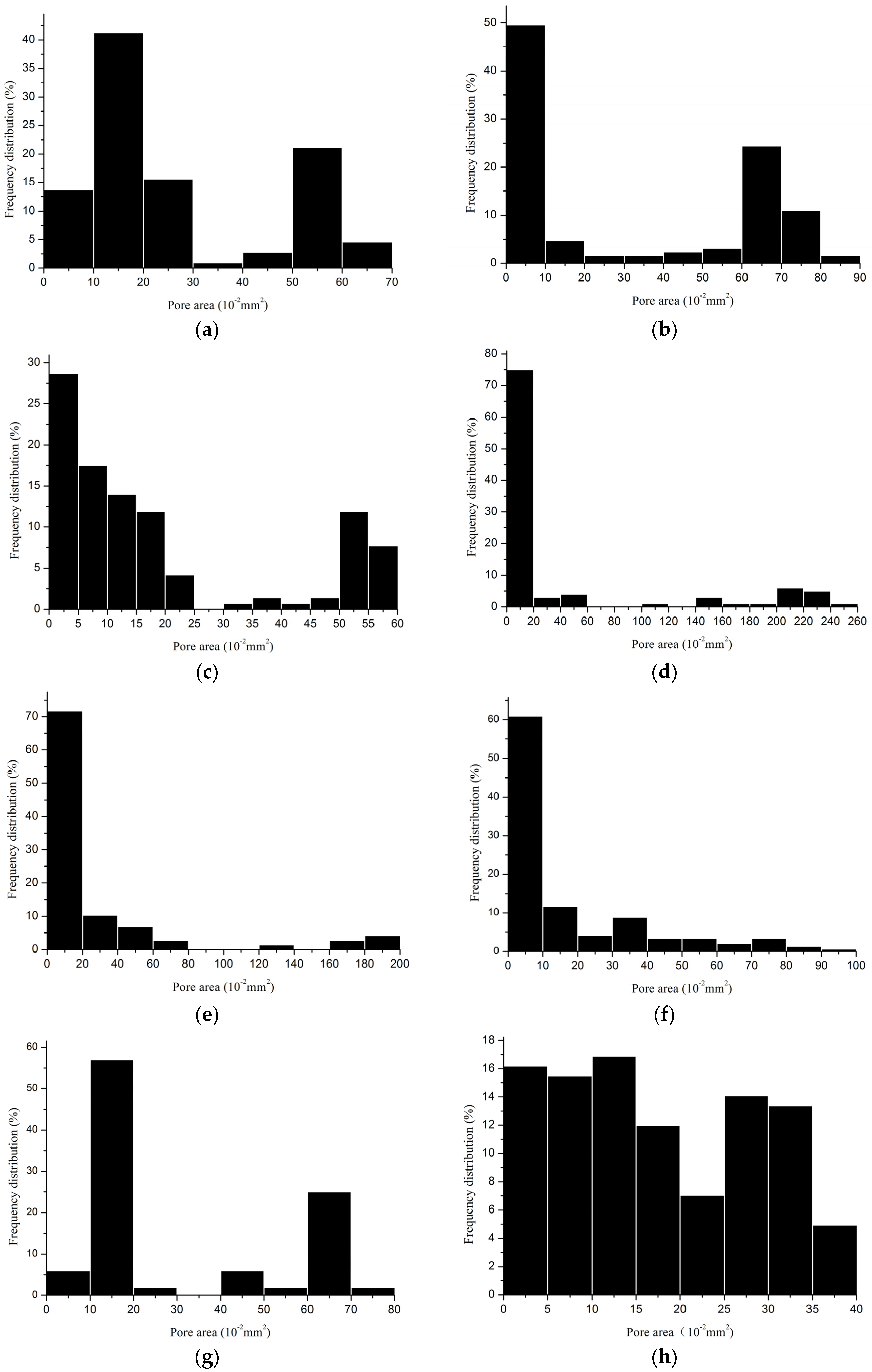
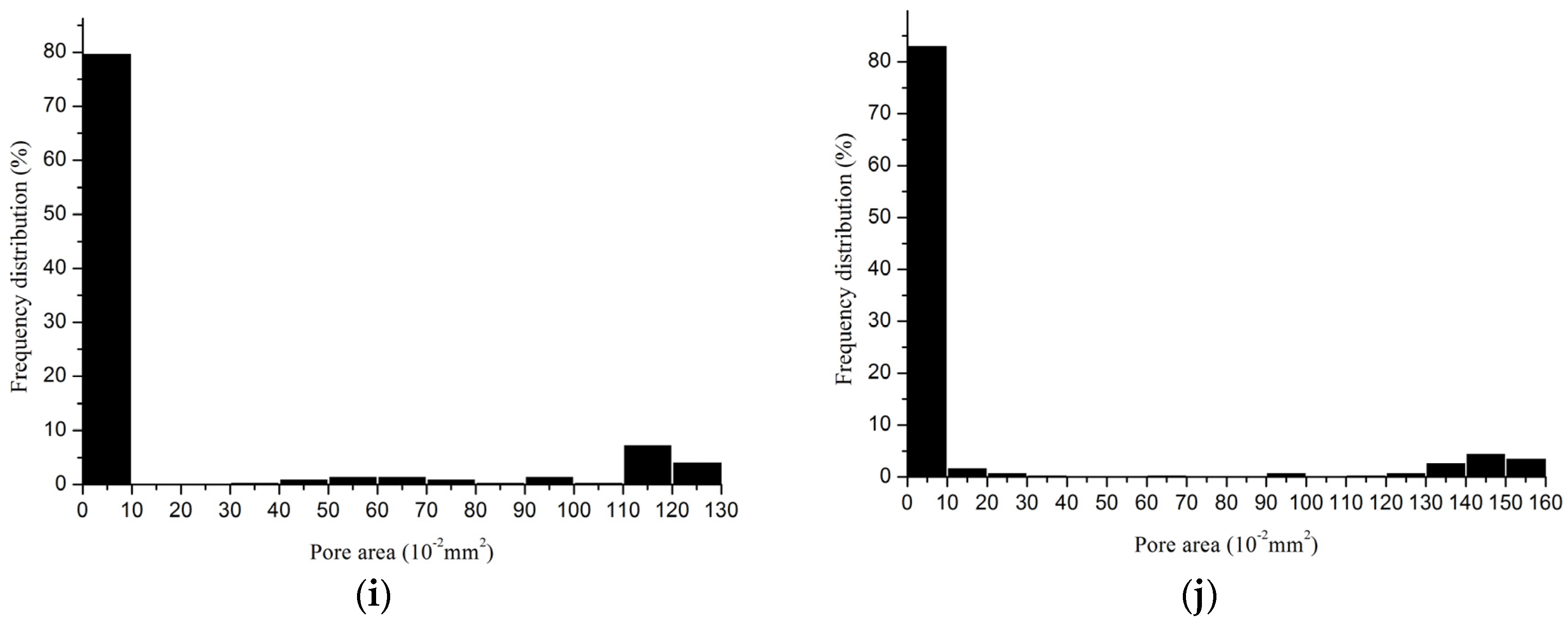
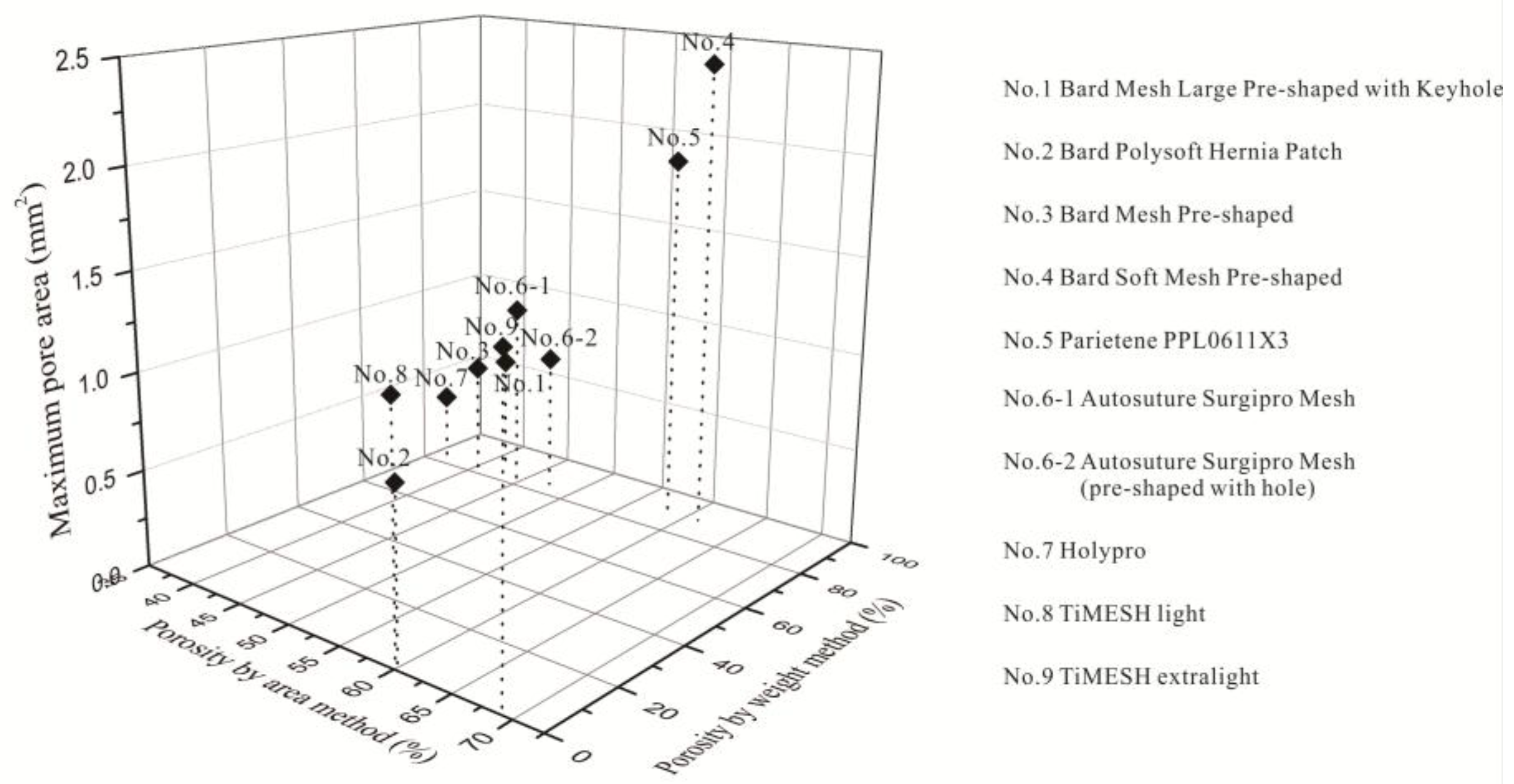
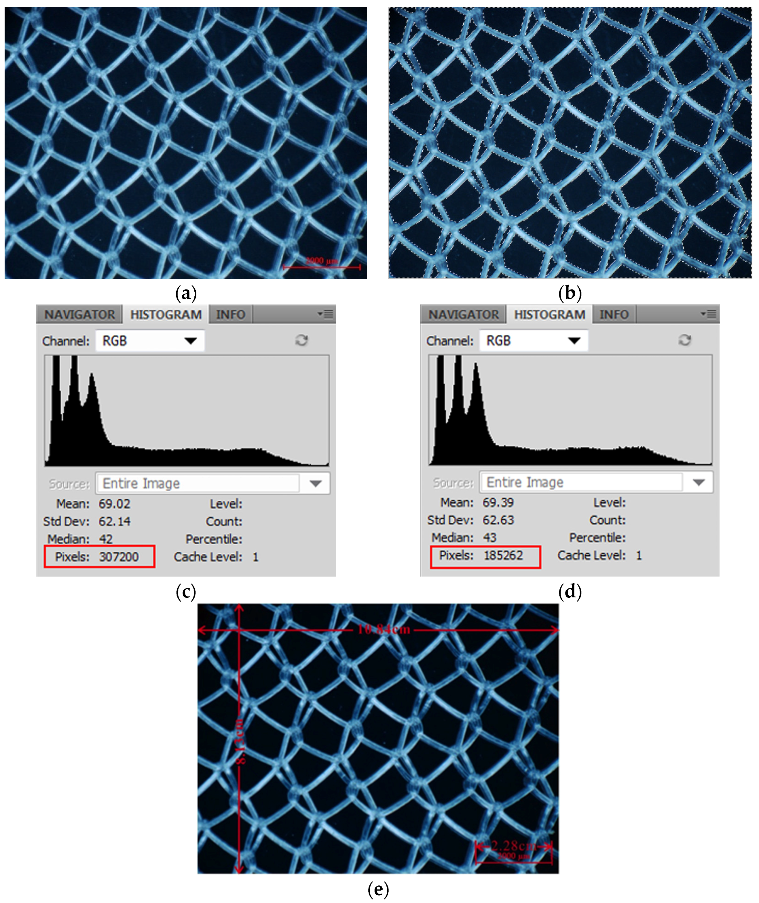
2.2.3. Porosity


| Device | Minimum Pore Size (mm2) | Maximum Pore Size (mm2) | Porosity (%) | Porosity I * (%) |
|---|---|---|---|---|
| 1 | 0.0007 | 0.6500 | 42.6 | 0 |
| 2 | 0.0018 | 0.8700 | 61.7 | 5.9 |
| 3 | 0.0040 | 0.5899 | 40.5 | 0 |
| 6-1 | 0.0065 | 0.9827 | 44.4 | 5.1 |
| 6-2 | 0.0096 | 0.7300 | 42.1 | 0 |
| 7 | 0.0012 | 0.3916 | 37.3 | 0 |
| Device | Minimum Pore Size (mm2) | Maximum Pore Size (mm2) | Porosity (%) | Porosity I * (%) |
|---|---|---|---|---|
| 4 | 0.0042 | 2.400 | 64.2 | 54.7 |
| 5 | 0.0044 | 1.900 | 58.2 | 30.8 |
| 8 | 0.0052 | 1.2517 | 60.1 | 46.2 |
| 9 | 0.0013 | 1.5776 | 69.2 | 60.1 |
2.3. Relationship between Different Properties of the Devices

3. Discussion
3.1. Physical Characteristics of Hernia Meshes
3.2. Pore Characteristics
3.3. Why Can the Same Lapping Structure Lead to Different Pore Characteristics?
3.4. Which Method Could Be Most Effective in Characterizing the Pore Size of Hernia Prostheses?
4. Materials and Methods
4.1. Selection of Devices
| Device | Company | Product Name | Gross Observation | Type of Materials | Filament Type |
|---|---|---|---|---|---|
| 1 | Bard | Bard Mesh Large Pre-shaped with Keyhole |  | Polypropylene | Monofilament |
| 2 | Bard | Bard Polysoft Hernia Patch | 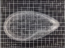 | Polypropylene | Monofilament |
| 3 | Bard | Bard Mesh Pre-shaped | 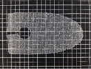 | Polypropylene | Monofilament |
| 4 | Bard | Bard Soft Mesh Pre-shaped | 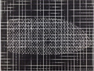 | Polypropylene | Monofilament |
| 5 | Sofradim Production | Parietene PPL0611X3 |  | Polypropylene | Monofilament |
| 6-1 | Covidien/Medtronic | Autosuture Surgipro Mesh | 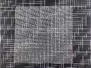 | Polypropylene | Monofilament |
| 6-2 | Covidien/Medtronic | Autosuture Surgipro Mesh | 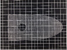 | Polypropylene | Monofilament |
| 7 | Holycon Medical Instrument Co., Ltd. | Holypro | 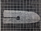 | Polypropylene | Monofilament |
| 8 | GfE Medizintechnik | TiMESH light | 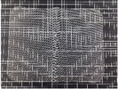 | Titanized polypropylene | Monofilament |
| 9 | GfE Medizintechnik | TiMESH extralight | 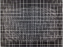 | Titanized polypropylene | Monofilament |
4.2. Methods
4.2.1. Surface Morphology
4.2.2. Textile Structure Characteristics
4.2.3. Physical Characteristics
4.3. Relationship between Prostheses Properties
5. Conclusions
Acknowledgments
Author Contributions
Conflicts of Interest
References
- Wahba, M. Evaluation of lightweight polypropylene mesh in Stoppa pre-peritoneal repair of bilateral inguinal hernias. J. Am. Sci. 2014, 10, 116–124. [Google Scholar]
- Molonby, G.; Gill, W.; Barclay, R. Operations for hernia technique of nylon darn. Lancet 1948, 252, 45–48. [Google Scholar] [CrossRef]
- Coda, A.; Lamberti, R.; Martorana, S. Classification of prosthetics used in hernia repair based on weight and biomaterial. Hernia 2012, 16, 9–20. [Google Scholar] [CrossRef] [PubMed]
- Lichtenstein, I.L.; Shulman, A.G.; Amid, P.K.; Montllor, M.M. The tension-free hernioplasty. Am. J. Surg. 1989, 157, 188–193. [Google Scholar] [CrossRef]
- Ger, R. The management of certain abdominal herniae by intra-abdominal closure of the neck of the sac. Ann. R. Coll. Surg. Engl. 1982, 64, 342–344. [Google Scholar] [PubMed]
- Schumpelick, V.; Treutner, K.; Arlt, G. Inguinal hernia repair in adults. Lancet 1994, 344, 375–379. [Google Scholar] [CrossRef]
- LeBlanc, K.A. Prostheses and products for hernioplasty. In Management of Abdominal Hernias, 4th ed.; Kingsnorth, A.K., LeBlanc, K.A., Eds.; Springer: London, UK, 2013; pp. 103–150. [Google Scholar]
- Miao, L.L.; Wang, F.; Wang, L.; Guidoin, R. Textile material used in hernia repair prostheses and its characteristics. J. Donghua Univ. 2014, 40, 758–766. [Google Scholar]
- Levy, A.H.; Wren, R.S.; Friedman, M.N. Complications and recurrences following inguinal hernia repair. Ann. Surg. 1951, 133, 533–539. [Google Scholar] [CrossRef] [PubMed]
- Lowham, A.S.; Filipi, C.J.; Fitzgibbons, R.J., Jr.; Stoppa, R.; Wantz, G.E.; Felix, E.L.; Crafton, W.B. Mechanisms of hernia recurrence after preperitoneal mesh repair. Traditional and laparoscopic. Ann. Surg. 1997, 225, 422–431. [Google Scholar] [CrossRef] [PubMed]
- Kukleta, J.F. Causes of recurrence in laparoscopic inguinal hernia repair. J. Minim. Access Surg. 2006, 2, 187–191. [Google Scholar] [CrossRef] [PubMed]
- Overview of Device Regulation. Available online: http://www.fda.gov/medicaldevices/deviceregulationandguidance/Overview/default.htm (accessed on 14 August 2015).
- Patel, H.; Ostergard, D.R.; Sternschuss, G. Polypropylene mesh and the host response. Int. Urogynecol. J. 2012, 23, 669–679. [Google Scholar] [CrossRef] [PubMed]
- Bilsel, Y.; Abci, I. The search for ideal hernia repair; mesh materials and types. Int. J. Surg. 2012, 10, 317–321. [Google Scholar] [CrossRef] [PubMed]
- Cobb, W.S.; Burns, J.M.; Kercher, K.W.; Matthews, B.D.; Norton, H.J.; Heniford, B.T. Normal intraabdominal pressure in healthy adults. J. Surg. Res. 2005, 129, 231–235. [Google Scholar] [CrossRef] [PubMed]
- Konerding, M.A.; Bohn, M.; Wolloscheck, T.; Batke, B.; Holste, J.-L.; Wohlert, S.; Trzewik, J.; Förstemann, T.; Hartung, C. Maximum forces acting on the abdominal wall: Experimental validation of a theoretical modeling in a human cadaver study. Med. Eng. Phys. 2011, 33, 789–792. [Google Scholar] [CrossRef] [PubMed]
- Junge, K.; Klinge, U.; Prescher, A.; Giboni, P.; Niewiera, M.; Schumpelick, V. Elasticity of the anterior abdominal wall and impact for reparation of incisional hernias using mesh implants. Hernia 2001, 5, 113–118. [Google Scholar] [PubMed]
- Förstemann, T.; Trzewik, J.; Holste, J.; Batke, B.; Konerding, M.; Wolloscheck, T.; Hartung, C. Forces and deformations of the abdominal wall—A mechanical and geometrical approach to the linea alba. J. Biomech. 2011, 44, 600–606. [Google Scholar] [CrossRef] [PubMed]
- Deeken, C.R.; Abdo, M.S.; Frisella, M.M.; Matthews, B.D. Physicomechanical evaluation of polypropylene, polyester, and polytetrafluoroethylene meshes for inguinal hernia repair. J. Am. Coll. Surg. 2011, 212, 68–79. [Google Scholar] [CrossRef] [PubMed]
- Maurer, M.; Röhrnbauer, B.; Feola, A.; Deprest, J.; Mazza, E. Mechanical biocompatibility of prosthetic meshes: A comprehensive protocol for mechanical characterization. J. Mech. Behav. Biomed. Mater. 2014, 40, 42–58. [Google Scholar] [CrossRef] [PubMed]
- Pott, P.P.; Schwarz, M.L.; Gundling, R.; Nowak, K.; Hohenberger, P.; Roessner, E.D. Mechanical properties of mesh materials used for hernia repair and soft tissue augmentation. PLoS ONE 2012, 7, 1–10. [Google Scholar] [CrossRef] [PubMed]
- Deeken, C.R.; Thompson, D.M.; Castile, R.M.; Lake, S.P. Biaxial analysis of synthetic scaffolds for hernia repair demonstrates variability in mechanical anisotropy, non-linearity and hysteresis. J. Mech. Behav. Biomed. Mater. 2014, 38, 6–16. [Google Scholar] [CrossRef] [PubMed]
- Li, X.; Kruger, J.A.; Jor, J.W.; Wong, V.; Dietz, H.P.; Nash, M.P.; Nielsen, P.M. Characterizing the ex vivo mechanical properties of synthetic polypropylene surgical mesh. J. Mech. Behav. Biomed. Mater. 2014, 37, 48–55. [Google Scholar] [CrossRef] [PubMed]
- Saberski, E.; Orenstein, S.; Novitsky, Y. Anisotropic evaluation of synthetic surgical meshes. Hernia 2011, 15, 47–52. [Google Scholar] [CrossRef] [PubMed]
- Anurov, M.; Titkova, S.; Oettinger, A. Biomechanical compatibility of surgical mesh and fascia being reinforced: Dependence of experimental hernia defect repair results on anisotropic surgical mesh positioning. Hernia 2012, 16, 199–210. [Google Scholar] [CrossRef] [PubMed]
- Choi, M.-S.; Ashdown, S.P. Effect of changes in knit structure and density on the mechanical and hand properties of weft-knitted fabrics for outerwear. Textile Res. J. 2000, 70, 1033–1045. [Google Scholar] [CrossRef]
- Cuden, A.P.; Hladnik, A.; Sluga, F. Impact of material, structure and relaxation process parameters of elasticized single-knitted fabrics on loop length. Textile Res. J. 2012. [Google Scholar] [CrossRef]
- Cobb, W.S.; Peindl, R.M.; Zerey, M.; Carbonell, A.M.; Heniford, B.T. Mesh terminology 101. Hernia 2009, 13, 1–6. [Google Scholar] [CrossRef] [PubMed]
- Klinge, U.; Klosterhalfen, B. Modified classification of surgical meshes for hernia repair based on the analyses of 1,000 explanted meshes. Hernia 2012, 16, 251–258. [Google Scholar] [CrossRef] [PubMed]
- Schmidbauer, S.; Ladurner, R.; Hallfeldt, K.; Mussack, T. Heavy-weight versus low-weight polypropylene meshes for open sublay mesh repair of incisional hernia. Eur. J. Med. Res. 2005, 10, 247–253. [Google Scholar] [PubMed]
- Bellón, J.; Rodríguez, M.; García-Honduvilla, N.; Gómez-Gil, V.; Pascual, G.; Buján, J. Comparing the behavior of different polypropylene meshes (heavy and lightweight) in an experimental model of ventral hernia repair. J. Biomed. Mater. Res. Part B. Appl. Biomater. 2009, 89, 448–455. [Google Scholar] [CrossRef] [PubMed]
- Śmietański, M.; Bury, K.; Śmietańska, I.; Owczuk, R.; Paradowski, T.; Group, P.H.S. Five-year results of a randomised controlled multi-centre study comparing heavy-weight knitted versus low-weight, non-woven polypropylene implants in lichtenstein hernioplasty. Hernia 2011, 15, 495–501. [Google Scholar] [CrossRef] [PubMed]
- Klinge, U.; Klosterhalfen, B.; Birkenhauer, V.; Junge, K.; Conze, J.; Schumpelick, V. Impact of polymer pore size on the interface scar formation in a rat model. J. Surg. Res. 2002, 103, 208–214. [Google Scholar] [CrossRef] [PubMed]
- Cobb, W.S.; Kercher, K.W.; Heniford, B.T. The argument for lightweight polypropylene mesh in hernia repair. Surg. Innov. 2005, 12, 63–69. [Google Scholar] [CrossRef] [PubMed]
- O’dwyer, P.J.; Kingsnorth, A.; Molloy, R.; Small, P.; Lammers, B.; Horeyseck, G. Randomized clinical trial assessing impact of a lightweight or heavyweight mesh on chronic pain after inguinal hernia repair. Brit. J. Surg. 2005, 92, 166–170. [Google Scholar] [CrossRef] [PubMed]
- Greca, F.; Paula, J.; Biondo-Simões, M.; Costa, F.; Silva, A.; Time, S.; Mansur, A. The influence of differing pore sizes on the biocompatibility of two polypropylene meshes in the repair of abdominal defects. Hernia 2001, 5, 59–64. [Google Scholar] [PubMed]
- Mühl, T.; Binnebösel, M.; Klinge, U.; Goedderz, T. New objective measurement to characterize the porosity of textile implants. J. Biomed. Mater. Res. B Appl. Biomater. 2008, 84, 176–183. [Google Scholar] [CrossRef] [PubMed]
- McDermott, M.; Isayeva, I.; Thomas, T.; Lee, A.; Lucas, A.; Witkowski, C.; Hutter, J. Characterization of the structure and properties of authentic and counterfeit polypropylene surgical meshes. Hernia 2006, 10, 131–142. [Google Scholar] [CrossRef] [PubMed]
- Pourdeyhimi, B. Porosity of surgical mesh fabrics: New technology. J. Biomed. Mater. Res. 1989, 23, 145–152. [Google Scholar] [CrossRef] [PubMed]
- Kirilova, M.; Stoytchev, S.; Pashkouleva, D.; Kavardzhikov, V. Experimental study of the mechanical properties of human abdominal fascia. Med. Eng. Phys. 2011, 33, 1–6. [Google Scholar] [CrossRef] [PubMed]
- Hollinsky, C.; Sandberg, S. Measurement of the tensile strength of the ventral abdominal wall in comparison with scar tissue. Clin. Biomech. 2007, 22, 88–92. [Google Scholar] [CrossRef] [PubMed]
- Gräβel, D.; Prescher, A.; Fitzek, S.; Keyserlingk, D.G.V.; Axer, H. Anisotropy of human linea alba: A biomechanical study. J. Surg. Res. 2005, 124, 118–125. [Google Scholar] [CrossRef] [PubMed]
- O’Brien, J.P.; Aneja, A.P. Fibres for the next millennium. Rev. Prog. Coloration 1999, 29, 1–7. [Google Scholar] [CrossRef]
- Acquaviva, D.; Bourret, P. Cure des éventrations par plaques de nylon. Press. Med. 1948, 56, 892. [Google Scholar]
- Wolstenholme, J.T. Use of commerical dacron fabric in the repair of inguinal hernias and abdominal wall defects. AMA Arch. Surg. 1956, 73, 1004–1008. [Google Scholar] [CrossRef] [PubMed]
- Usher, F.; Gannon, J. Marlex mesh, a new plastic mesh for replacing tissue defects. J. Occup. Environ. Med. 1959, 78, 138–145. [Google Scholar]
- Sternschuss, G.; Ostergard, D.R.; Patel, H. Post-implantation alterations of polypropylene in the human. J. Urol. 2012, 188, 27–32. [Google Scholar] [CrossRef] [PubMed]
- Iakovlev, V.V.; Guelcher, S.A.; Bendavid, R. Degradation of polypropylene in vivo: A microscopic analysis of meshes explanted from patients. J. Biomed. Mater. Res. B. 2015. [Google Scholar] [CrossRef] [PubMed]
- Berger, D.; Bientzle, M. Polyvinylidene fluoride: A suitable mesh material for laparoscopic incisional and parastomal hernia repair! Hernia 2009, 13, 167–172. [Google Scholar] [CrossRef] [PubMed]
- Mary, C.; Marois, Y.; King, M.W.; Laroche, G.; Douville, Y.; Martin, L.; Guidoin, R. Comparison of the in vivo behavior of polyvinylidene fluoride and polypropylene sutures used in vascular surgery. ASAIO J. 1998, 44, 199–206. [Google Scholar] [CrossRef] [PubMed]
- Hazebroek, E.J.; Ng, A.; Yong, D.H.; Berry, H.; Leibman, S.; Smith, G.S. Evaluation of lightweight titanium-coated polypropylene mesh (timesh) for laparoscopic repair of large hiatal hernias. Surg. Endosc. 2008, 22, 2428–2432. [Google Scholar] [CrossRef] [PubMed]
- Earle, D.B.; Mark, L.A. Prosthetic material in inguinal hernia repair: How do I choose? Surg. Clin. N. Am. 2008, 88, 179–201. [Google Scholar] [CrossRef] [PubMed]
- Bruckschen, B.; Seitz, H.; Buzug, T.; Tille, C.; Leukers, B.; Irsen, S. Comparing different porosity measurement methods for characterisation of 3D printed bone replacement scaffolds. Biomed. Tech. 2005, 50, 1609–1610. [Google Scholar]
- Karageorgiou, V.; Kaplan, D. Porosity of 3D biomaterial scaffolds and osteogenesis. Biomaterials 2005, 26, 5474–5491. [Google Scholar] [CrossRef] [PubMed]
- Baldwin, C.A.; Sederman, A.J.; Mantle, M.D.; Alexander, P.; Gladden, L.F. Determination and characterization of the structure of a pore space from 3D volume images. J. Colloid Interface Sci. 1996, 181, 79–92. [Google Scholar] [CrossRef]
- McKenzie, D.; McFall, W.; Sainty, W.; Yin, Y.; Durandet, A.; Boswell, R. New technology for PACVD. Surf. Coat. Tech. 1996, 82, 326–333. [Google Scholar] [CrossRef]
- Mathur, S.; Kuhn, P. CVD of titanium oxide coatings: Comparative evaluation of thermal and plasma assisted processes. Surf. Coat. Tech. 2006, 201, 807–814. [Google Scholar] [CrossRef]
- ISO 7198: 1998 Cardiovascular Implant-Tubular Vascular Prostheses; International Organization for Standardization (ISO): Geneva, Switzerland, 1998.
© 2015 by the authors; licensee MDPI, Basel, Switzerland. This article is an open access article distributed under the terms and conditions of the Creative Commons by Attribution (CC-BY) license (http://creativecommons.org/licenses/by/4.0/).
Share and Cite
Miao, L.; Wang, F.; Wang, L.; Zou, T.; Brochu, G.; Guidoin, R. Physical Characteristics of Medical Textile Prostheses Designed for Hernia Repair: A Comprehensive Analysis of Select Commercial Devices. Materials 2015, 8, 8148-8168. https://doi.org/10.3390/ma8125453
Miao L, Wang F, Wang L, Zou T, Brochu G, Guidoin R. Physical Characteristics of Medical Textile Prostheses Designed for Hernia Repair: A Comprehensive Analysis of Select Commercial Devices. Materials. 2015; 8(12):8148-8168. https://doi.org/10.3390/ma8125453
Chicago/Turabian StyleMiao, Linli, Fang Wang, Lu Wang, Ting Zou, Gaétan Brochu, and Robert Guidoin. 2015. "Physical Characteristics of Medical Textile Prostheses Designed for Hernia Repair: A Comprehensive Analysis of Select Commercial Devices" Materials 8, no. 12: 8148-8168. https://doi.org/10.3390/ma8125453