
Experimental Characterization of the Properties of Double-Lap Needled and Hybrid Joints of Carbon/Epoxy Composites


Abstract
:1. Introduction
2. Materials and Experimental Technique

| Young’s Modulus, E11, GPa | Poisson’s Ratio ν21 | Poisson’s Ratio ν31 | Ultimate Tensile Strength σ11, MPa |
|---|---|---|---|
| 76.7 ± 0.8 | 0.44 ± 0.03 | 0.042 ± 0.003 | 520 ± 26 |
| Tensile Modulus of Elasticity, GPa | Tensile Yield Point, MPa | Ultimate Elongation, % | Poisson’s Ratio ν | Shear Modulus, GPa |
|---|---|---|---|---|
| 200 | 420 | 18 | 0.31 | 80.0 |

| Tensile Modulus, GPa | Tensile Strength, MPa | Ultimate Strain, % | Poisson’s Ratio ν |
|---|---|---|---|
| 1.93 | 42.0 | 3 | 0.31 |

3. Results and Discussion

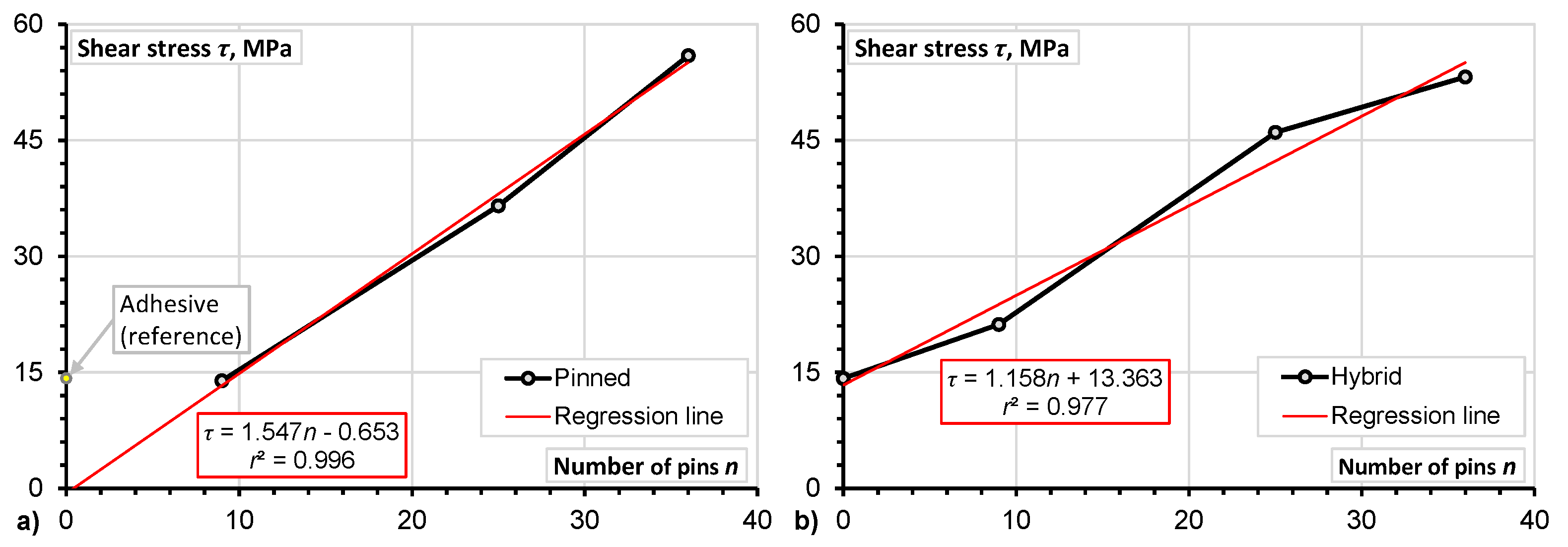
- Improvement of the mechanical properties of DLJ is significantly correlated with the number of pins (the minimum value of the determination coefficient r2 is equal to 0.94).
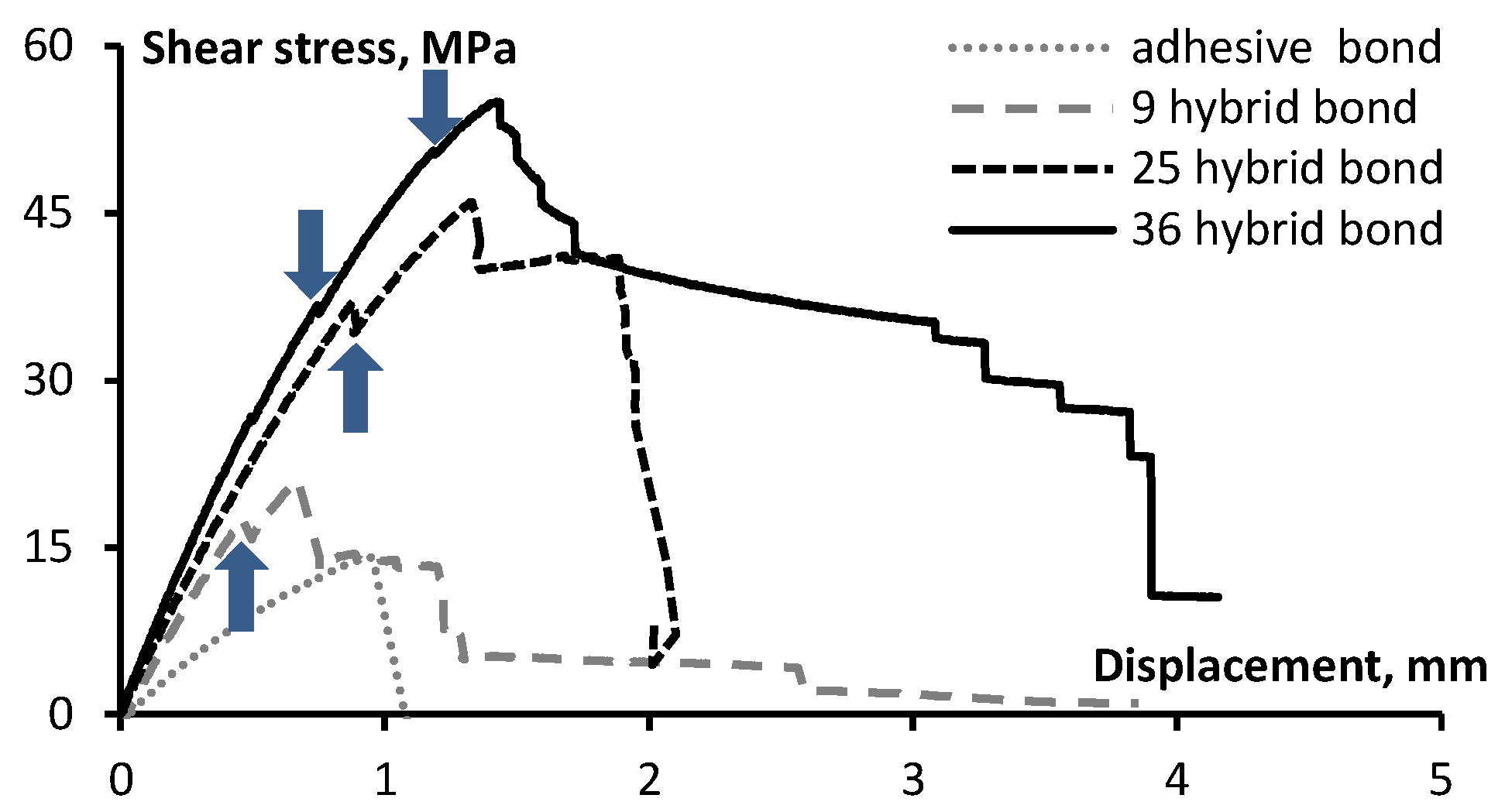
- Application of z-pins improved the mechanical properties of DLJ. As can be observed from Table 4, the strength and the stiffness (calculated in the range from 0% to 10% of the ultimate load) of the pinned-only joints was increased by 300% and 120%, respectively. For the hybrid joints, the increase in both strength and stiffness was the same (i.e., 280%).
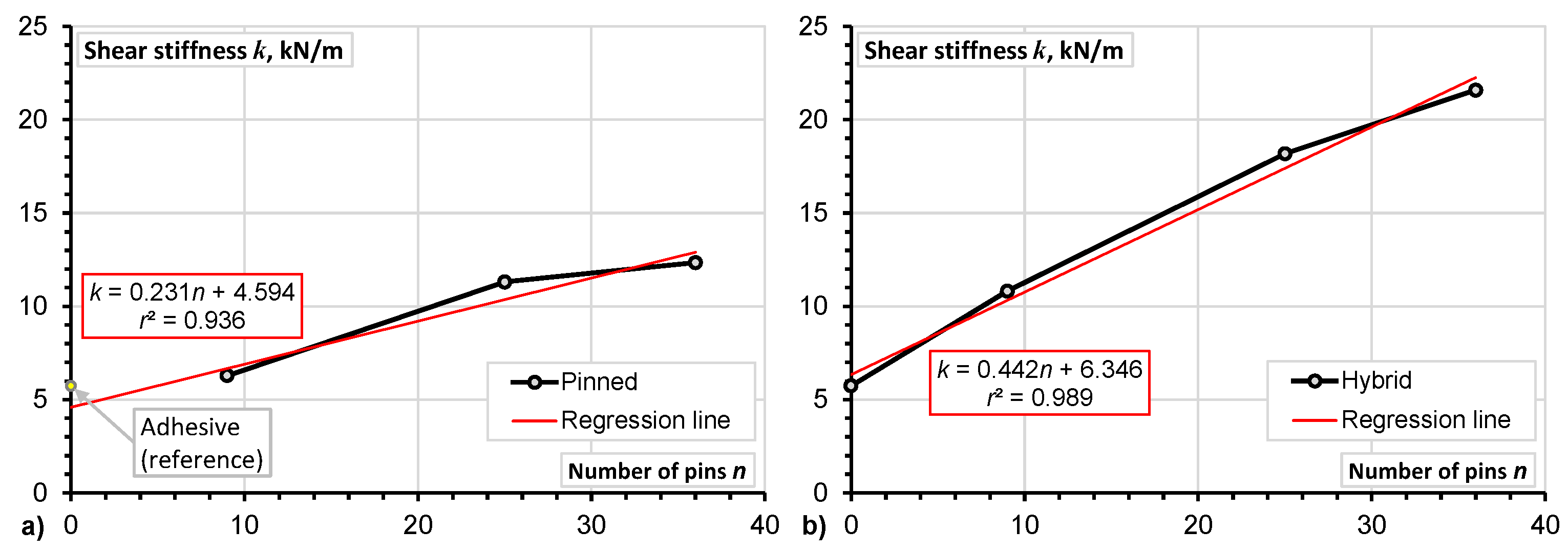
- Increment in the shear strength related to the number of pins is less significant in the hybrid DLJ in comparison with the pinned ones (compare the slope coefficients of the regression line, which are equal to 1.547 and 1.158 for the hybrid and pinned joints, respectively). Considering the shear stiffness, the opposite tendency can be evidenced from Figure 8. For instance, the shear stiffness of the hybrid DLJ with 36 pins is 1.7 times higher than that of a similar pinned joint (Table 4). Most probably, this effect is the consequence of the effective composite action between z-pins and adhesive achieved in the proposed hybrid DLJ.
- The hybrid connection reduces deformability of the joint – the elongation corresponding to the maximum load of the pinned DLJ was twice the hybrid counterpart one (Table 4).


| Joint Type | Number of z-Pins | Ultimate Shear Strength , MPa | Elongation at the Ultimate Load, mm | Shear Stiffness, kN/m |
|---|---|---|---|---|
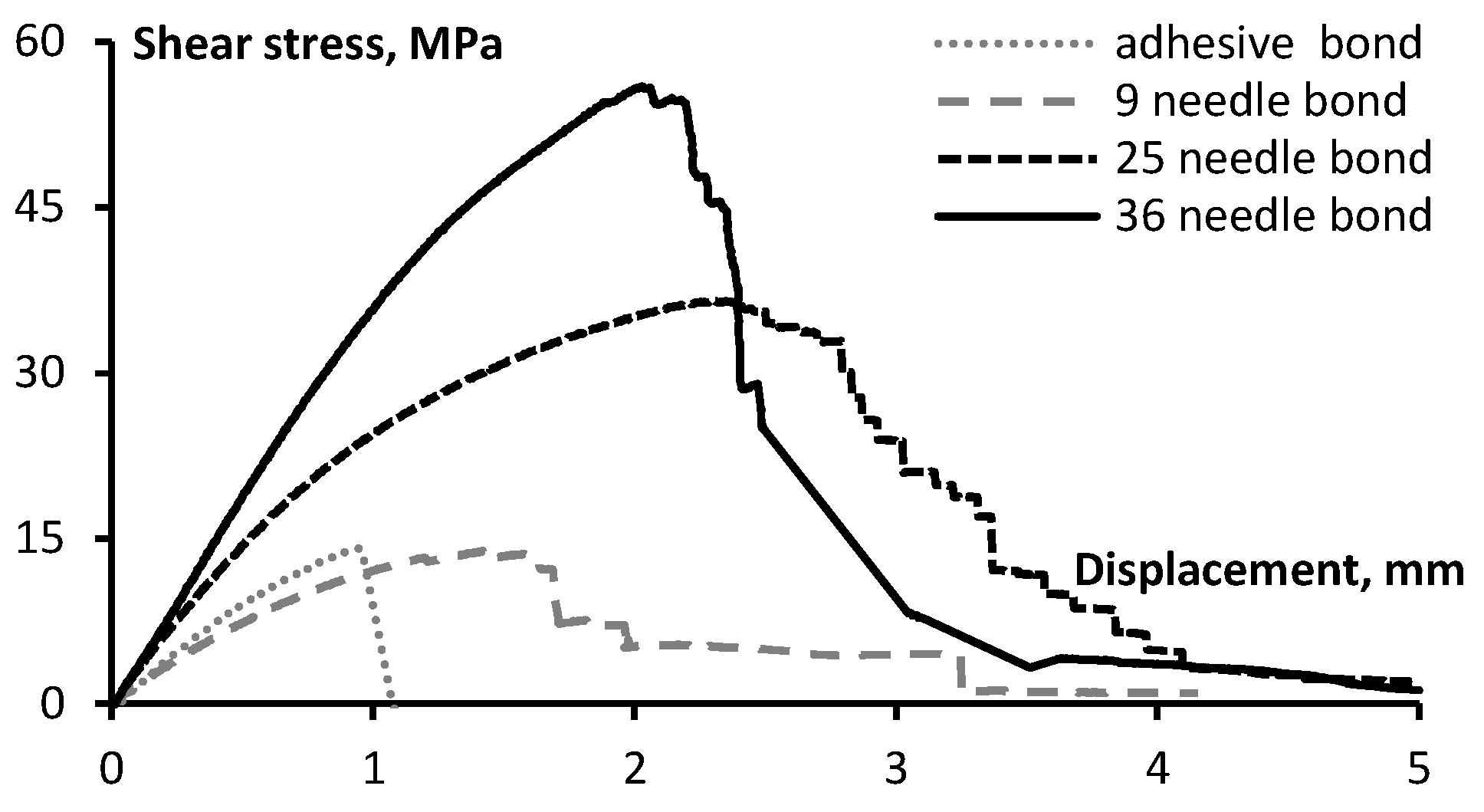
| Adhesive (reference) | 0 | 14.2 ± 2.5 | 0.95 ± 0.09 | 5.7 ± 0.6 |
| Needled bond | 9 | 13.9 ± 3.2 | 1.42 ± 0.25 | 6.3 ± 0.7 |
| Needled bond | 25 | 36.5 ± 5.1 | 2.31 ± 0.28 | 11.3 ± 0.9 |
| Needled bond | 36 | 55.9 ± 6.2 | 2.03 ± 0.29 | 12.3 ± 0.7 |
| Hybrid bond | 9 | 21.2 ± 2.4 | 0.67 ± 0.19 | 10.8 ± 0.6 |
| Hybrid bond | 25 | 46.0 ± 2.9 | 1.34 ± 0.31 | 18.2 ± 0.8 |
| Hybrid bond | 36 | 53.7 ± 3.3 | 1.56 ± 0.31 | 21.6 ± 1.2 |

4. Conclusions
- Improvement of the mechanical properties of DLJ is significantly correlated with the number of z-pins: the strength and stiffness (calculated in the range from 0% to 10% of the ultimate load) of DLJ increased up to 300% and 280%, respectively.
- Increment in the shear strength related to the number of pins is less significant in the hybrid DLJ compared to the pinned ones. However, the opposite tendency was evidenced considering the shear stiffness of the joints. The shear stiffness of the hybrid DLJ with 36 pins was found to be 1.7 times higher than that of a similar pinned joint.
- The hybrid connection reduces deformability of the joint—the elongation corresponding to the maximum load of the pinned DLJ was twice that of the hybrid counterpart.
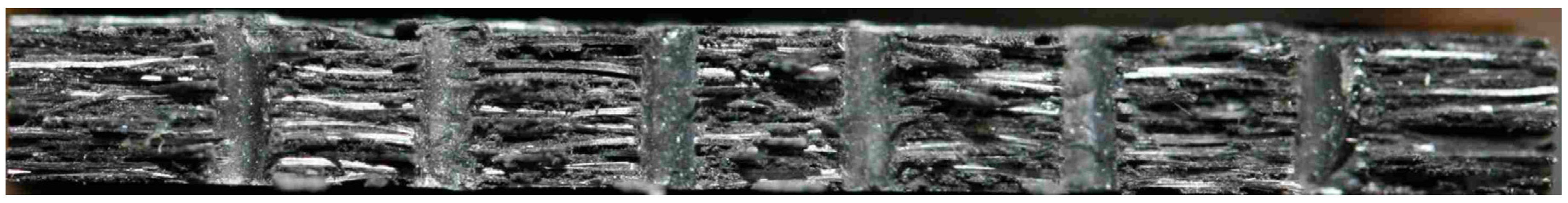
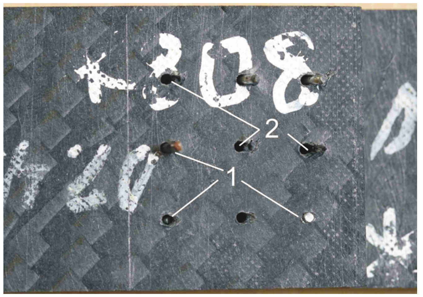
- The observed bridging effect of the z-pins, transferring the shear stresses through the crack, is the general benefit of the pinned DLJ compared with the reference adhesive joints, the failure of which was their brittleness.
Acknowledgments
Author Contributions
Conflicts of Interest
References
- Gillespie, J.W.; Bourban, P.E.; Tieerney, J.J. Joining of Composites. In Comprehensive Composite Materials. Polymer Matrix Composites; Talreja, R., Manson, I.A.E., Eds.; Elsevier: Amsterdam, The Netherlands, 2000. [Google Scholar]
- Whitney, J.M.; Nuismer, R.J. Stress fracture criteria for laminated composites containing stress concentrations. J. Compos. Mater. 1974, 8, 253–265. [Google Scholar] [CrossRef]
- Lekhnitskii, S.G. Anisotropic Plates, 2nd ed.; Tsai, S.W., Cheron, T., Eds.; Gordon and Breach Science Publishers Inc.: New York, NY, USA, 1968. [Google Scholar]
- Callus, P.J. The Effects of Hole-Size and Environment on the Mechanical Behaviour of a Quasi-Isotropic AS4/3501–6 Laminate in Tension, Compression and Bending; Technical Report 6a N DSTO-TR-2077; Defence Science and Technology Organization: Fishermans Bend, Australia, 2007. [Google Scholar]
- Konish, H.J.; Whitney, J.M. Approximate stresses in an orthotropic plate containing a circular hole. J. Compos. Mater. 1975, 9, 157–166. [Google Scholar] [CrossRef]
- Nuismer, R.J.; Whitney, J.M. Uniaxial failure of composite laminates containing stress concentrations. Fract. Mech. Compos. ASTM STP 1975, 593, 1–117. [Google Scholar]
- Lee, C.; Liu, D. Tensile strength of stitching joint in woven glass fabrics. J. Eng. Mater. Technol. 1990, 112, 125–130. [Google Scholar] [CrossRef]
- Sawyer, J.W. Effect of stitching on the strength of bonded composite single lap joints. AIAA J. 1985, 23, 1744–1748. [Google Scholar] [CrossRef]
- Tong, L.; Cleaves, K.; Kruckenburg, T.; Stevens, G.P. Strength of RTM single lap joints with transverse stitching. Key Eng. Mater. 1998, 137, 195–202. [Google Scholar] [CrossRef]
- Aymerich, F. Effect of stitching on the static and fatigue performance of co-cured composite single-lap joints. J. Compos. Mater. 2004, 36, 243–257. [Google Scholar] [CrossRef]
- Chang, P.; Mouritz, A.P.; Cox, B.N. Properties and failure mechanisms of pinned composite lap joints in monotonic and cyclic tension. Compos. Sci. Technol. 2006, 66, 2163–2176. [Google Scholar] [CrossRef]
- Aymerich, F.; Onnis, R.; Priolo, P. Analysis of the fracture of a stitched single-lap joint. Compos. A Appl. Sci. Manuf. 2005, 36, 603–614. [Google Scholar] [CrossRef]
- Tong, L.; Jain, L.K. Analysis of adhesive bonded composite lap joints with transverse stitching. Appl. Compos. Mater. 1995, 2, 343–365. [Google Scholar] [CrossRef]
- Rugg, K.L.; Cox, B.N.; Massabo, R. Mixed mode delamination of polymer composite laminates reinforced through the thickness by Z-fibers. Compos. A Appl. Sci. Manuf. 2002, 33, 177–190. [Google Scholar] [CrossRef]
- Massabo, R.; Mumm, D.R.; Cox, B.N. Characterizing mode II delamination cracks in stitched composites. Int. J. Fract. 1998, 92, 1–38. [Google Scholar] [CrossRef]
- Glaessgen, E.H.; Raju, I.S.; Poe, C.C., Jr. Analytical and experimental studies of the debonding of stitched and unstitched composite joints. J. Compos. Mater. 2002, 36, 2599–2622. [Google Scholar] [CrossRef]
- Byun, J.H.; Gillespie, J.W.; Chou, T.W. Mode I delamination of a three-dimensional fabric composite. J. Compos. Mater. 1990, 24, 497–518. [Google Scholar] [CrossRef]
- Tomashevskii, V.T.; Romanov, D.A.; Shalygin, V.N.; Panfilov, N.A. Radial reinforcement effect on the strength of fiberglas reinforced plastic shells under external pressure. Mekh. Kompoz. Mater. 1980, 2, 205–210. [Google Scholar]
- Freitas, G.; Magee, C.; Dardzinski, P.; Fusco, T. Fiber insertion process for improved damage tolerance in aircraft laminates. J. Adv. Mater. 1994, 25, 36–43. [Google Scholar]
- Huang, S.L.; Richey, R.J.; Deska, E.W. Cross Reinforcement in a GR/EP Laminate. In Proceedings of the ASME, Winter Annual Meeting, San Francisco, CA, USA, 10–15 December 1978.
- Mouritz, A.P. Review of z-pinned composite laminates. Compos. A Appl. Sci. Manuf. 2007, 38, 2383–2397. [Google Scholar] [CrossRef]
- Sika Corporation. Sikadur® 52. Product Data Sheet; Sika Corporation: Lyndhurst, NJ, USA, 2014. [Google Scholar]
© 2015 by the authors; licensee MDPI, Basel, Switzerland. This article is an open access article distributed under the terms and conditions of the Creative Commons by Attribution (CC-BY) license (http://creativecommons.org/licenses/by/4.0/).
Share and Cite
Arnautov, A.; Nasibullins, A.; Gribniak, V.; Blumbergs, I.; Hauka, M. Experimental Characterization of the Properties of Double-Lap Needled and Hybrid Joints of Carbon/Epoxy Composites. Materials 2015, 8, 7578-7586. https://doi.org/10.3390/ma8115410
Arnautov A, Nasibullins A, Gribniak V, Blumbergs I, Hauka M. Experimental Characterization of the Properties of Double-Lap Needled and Hybrid Joints of Carbon/Epoxy Composites. Materials. 2015; 8(11):7578-7586. https://doi.org/10.3390/ma8115410
Chicago/Turabian StyleArnautov, A., A. Nasibullins, V. Gribniak, I. Blumbergs, and M. Hauka. 2015. "Experimental Characterization of the Properties of Double-Lap Needled and Hybrid Joints of Carbon/Epoxy Composites" Materials 8, no. 11: 7578-7586. https://doi.org/10.3390/ma8115410