Laser Peening Process and Its Impact on Materials Properties in Comparison with Shot Peening and Ultrasonic Impact Peening

Abstract
:1. Introduction
2. Laser Shock Peening
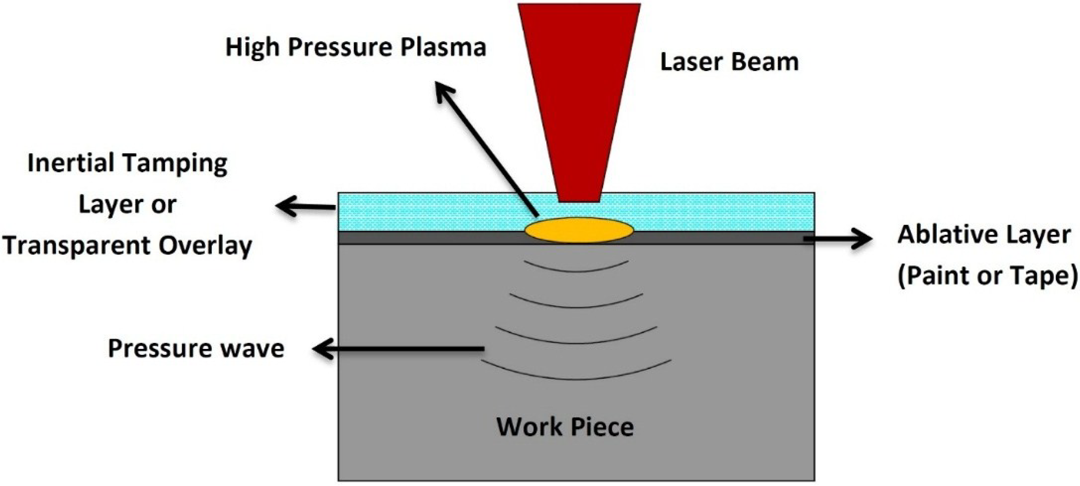
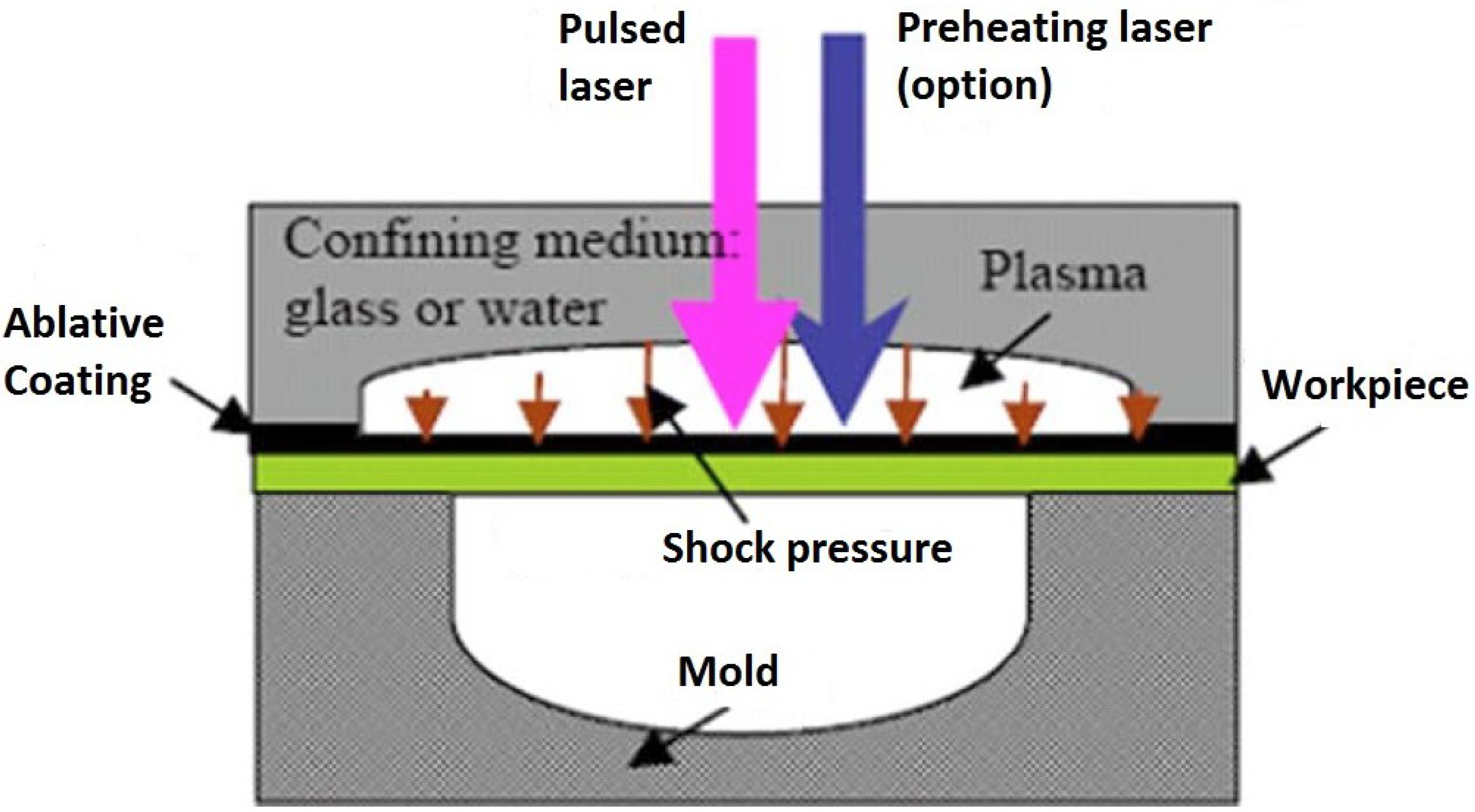
2.1. Generation of Laser Shock Waves

2.2. Process Parameters for Laser Shock Peening

| Target material | Z1 × 106 (g/cm2s) (Reference) | Confining medium | Z2 × 106 (g/cm2s) (Reference) |
|---|---|---|---|
| Ti-6Al-4V | 2.75 [65] | Water | 0.17 [65] |
| AA7050-T7451 | 1.50 [77] | Perpex | 0.32 [64] |
| SS304 | 3.61 [68] | Silicon rubber | 0.47 [64] |
| Mg-Ca | 0.88 [79] | K9 Glass | 1.14 [64], 1.5 [68] |
| AISI 4140 | 3.96 [69] | Quartz Glass | 1.31 [64] |
| Cu | 0.16 [80] | Pb Glass | 1.54 [64] |
| SS321 | 4.00 [81] | BK Glass | 1.44 [69] |
2.3. Laser Peened Materials
| Material (Reference) | Power density (GW/cm2) | Pulse duration (ns) | Absorbent coating | Transparent overlay | Remarks |
|---|---|---|---|---|---|
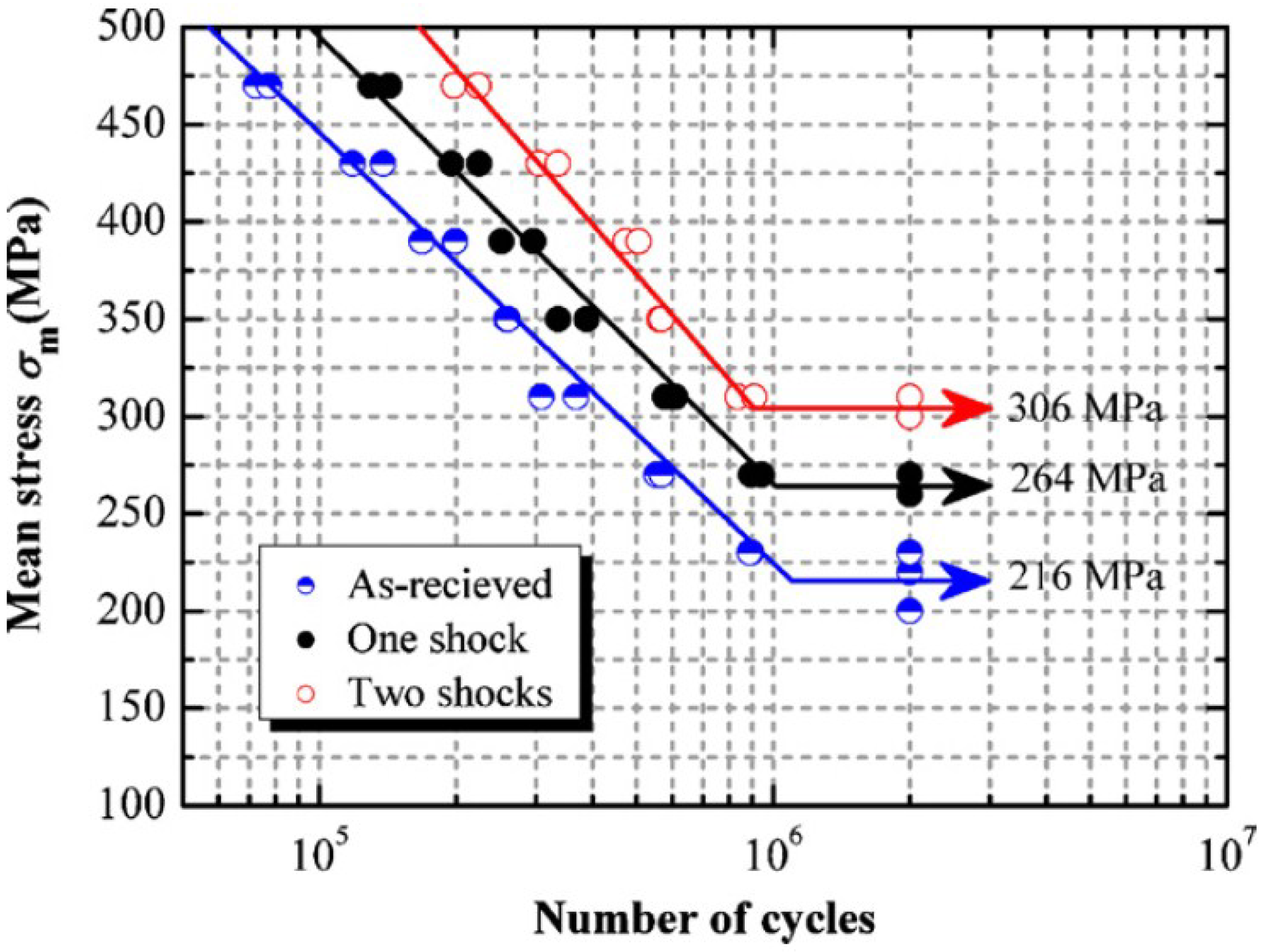
| Ti-6Al-4V [53] | 5 | 10 | Al Foil | Water | The fatigue life was improved by 22.2% and 41.7% for one and two successive laser shocks respectively as compared to as-received sample. |
| Ti-17 [82] | 3, 6, 9 | 9, 27 | Al | Water | It was found that all LSP parameters had influence on the residual stress profile. LSP had no influence on roughness, little effect on work hardening and large effect on hardness due to the compressive stresses induced. |
| AA2195 [60] | 5 | 18 | Al | Water | The fatigue crack growth rate of stir welded joint was reduced using LSP as compared to SP. Furthermore, the reduced crack growth rate was comparable with unwelded material. |
| Al2024 T3 [83] | 5 | 18 | Black paint | Water | LSP specimen showed resistance to fatigue crack growth for various notch geometries as compared to unpeened specimen. |
| 4140 Steel [84] | 3 | 5 | Al | BK7 Glass | WLSP and DSA showed improved fatigue life due to enhanced cyclic stability of compressive RS. The stability and reliability were attributed to the enhanced dislocation pinning effect associated with the WLSP and DSA process. |
| 316 L SS [85] | 2.5 | 10 | No coating | Water | The potentiodynamic polarization investigation showed improvement in corrosion potential (Ecorr) and corrosion current density (Icorr) with increase in laser pulse density. LPwC specimen showed 30%–40% increase in microhardness than unpeened specimen. |
| 2204 Duplex SS [86] | 900, 1600, 2500 pul/cm2 | 8 | No | Water | Greater RS were observed with higher pulse density. LSP showed improved crack growth rate resistance and fracture toughness as compared to untreated specimen. |
| Cu 15 µm foil [87] | 6 | 10 | Black paint | Water | The microscale laser dynamic forming (µLDF) showed that, materials are strengthened due to refined grains and large dislocation density which were dominant in the microstructure. |
| Alloy 22 [88] | 10 | 25 | Al | Water | Slitting method was used to establish a relationship between LSP parameters and RS on flat coupons. While contour method measured the spatial RS on critical geometrical features. |
| Inconel 600 [89] | 10 J/cm2 | 12 | - | Water Jacket | Tilted column microstructure was observed due to overlapping of laser spots during scanning. Spherical nanoparticles with 60 nm diameter were seen due to laser ablation. |
| Fe-3%Si [4] | 0.1–1 | 25–200 | Pb | Quartz | Laser shocking showed that quartz plus lead overlay gave the most deformation for a given power density. The deformation occurred by slip and twining mechanism. Most of the samples showed surface melting for 200 ns pulses. |
| Mg-Ca [79] | 78 | 5 to 7 | Black paint | Water | Sequential peening showed an increase in the tensile pile up region up to 50% which was considered applicable for orthopaedic applications. |
| AZ31B Mg [90] | 5 | 23 | Al7075 | Water | Sub-grain sizes of 5.8 µm were obtained after four laser impacts. The RS near the surface increased with number of impacts. LSP showed retardation to SCC crack initiation and propagation. |
| Brass H62 [91] | 1000, 2000, 3000 Pulses/cm2 | 10 | - | Water | LSP showed that, the higher the pulse density the higher the microhardness, roughness and wear resistance. No observable features in the microstructure after LSP. |
| CMSX, AM1, Astroloy [92] | 12–150, 90, 25 | 25, 33, 40 | Black paint | Water, Glass | The deformation microstructure and macroscopic mechanical phenomenon studies were envisioned to provide optimum process parameters applied to fatigue and fretting fatigue specimens. |
2.4. Characterization of Laser Shock Peened Materials
3. Effect of Laser Shock Peening
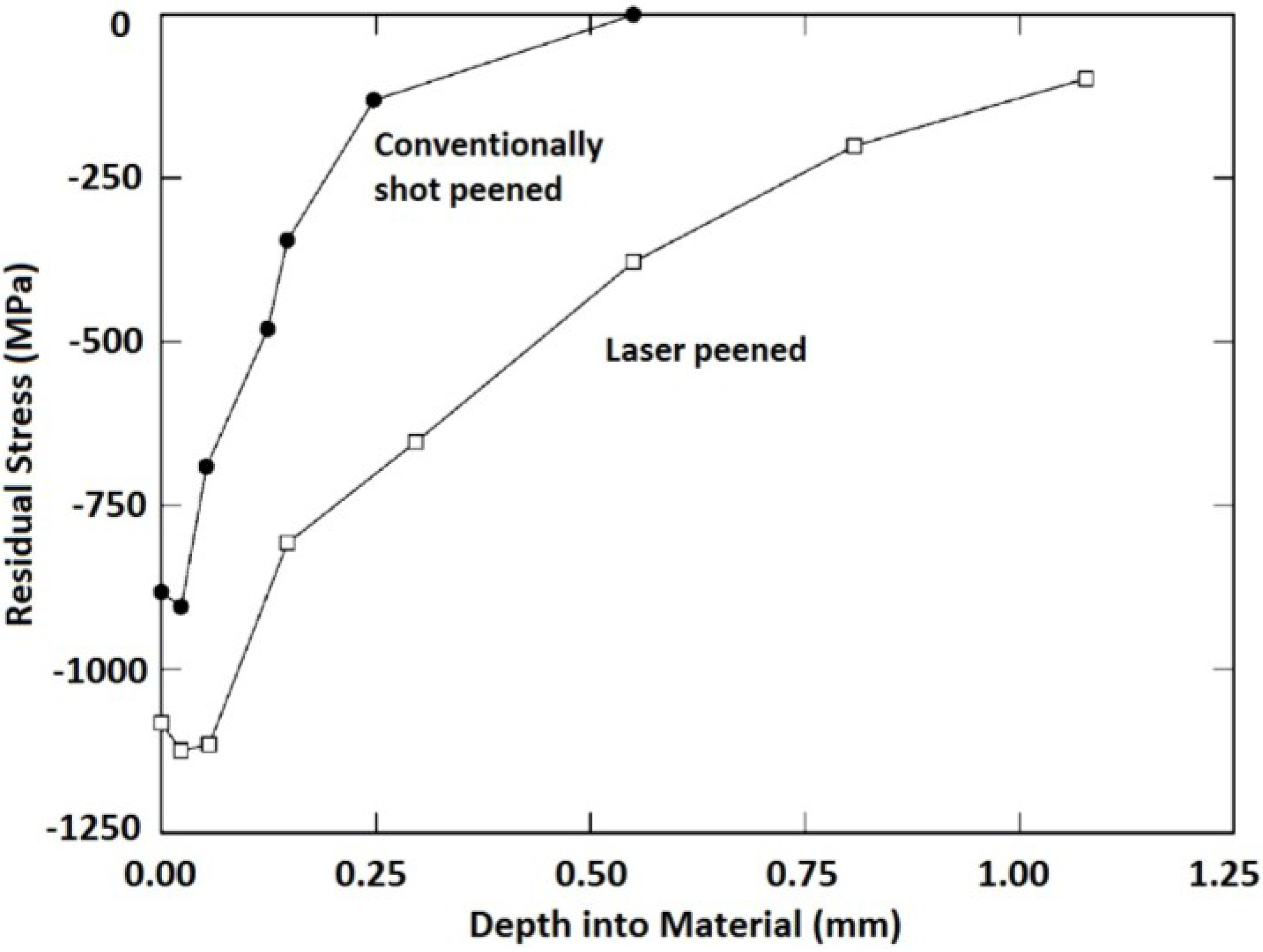
3.1. Residual Stress

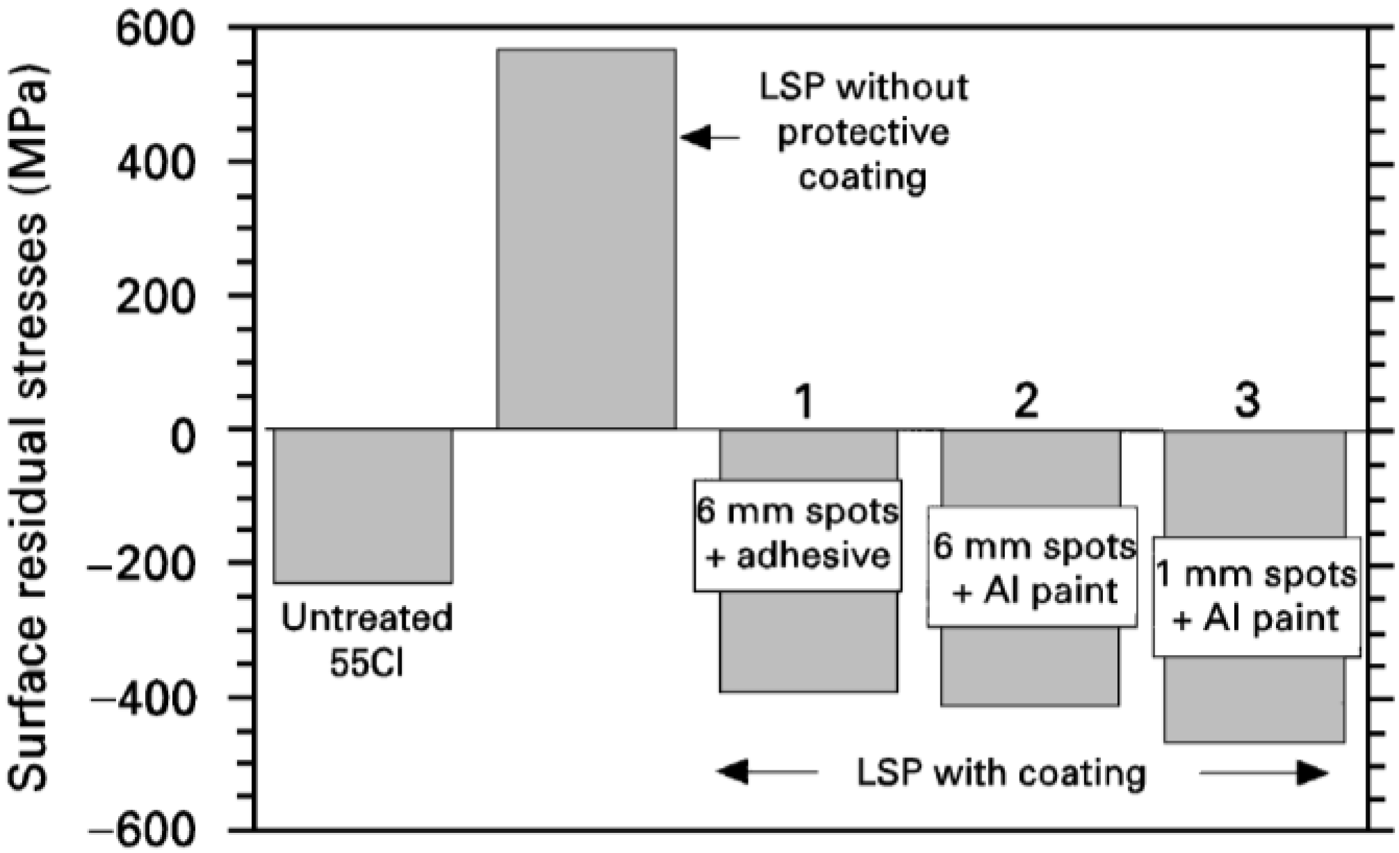
3.1.1. Residual Stress and Ablative Layer (Coating)
3.1.2. Residual Stress and Confining Medium
3.1.3. Residual Stress and Laser Spot Size and Shape
| Specimen | Spot size (mm) | δmin (MPa) | δmax (MPa) |
|---|---|---|---|
| 1 | - | 22 ± 17 | 45 ± 22 |
| 2 | 1.5 | −362 ± 31 | −199 ± 27 |
| 3 | 2.0 | −347 ± 28 | −142 ± 23 |
| 4 | 2.5 | −258 ± 24 | −138 ± 22 |
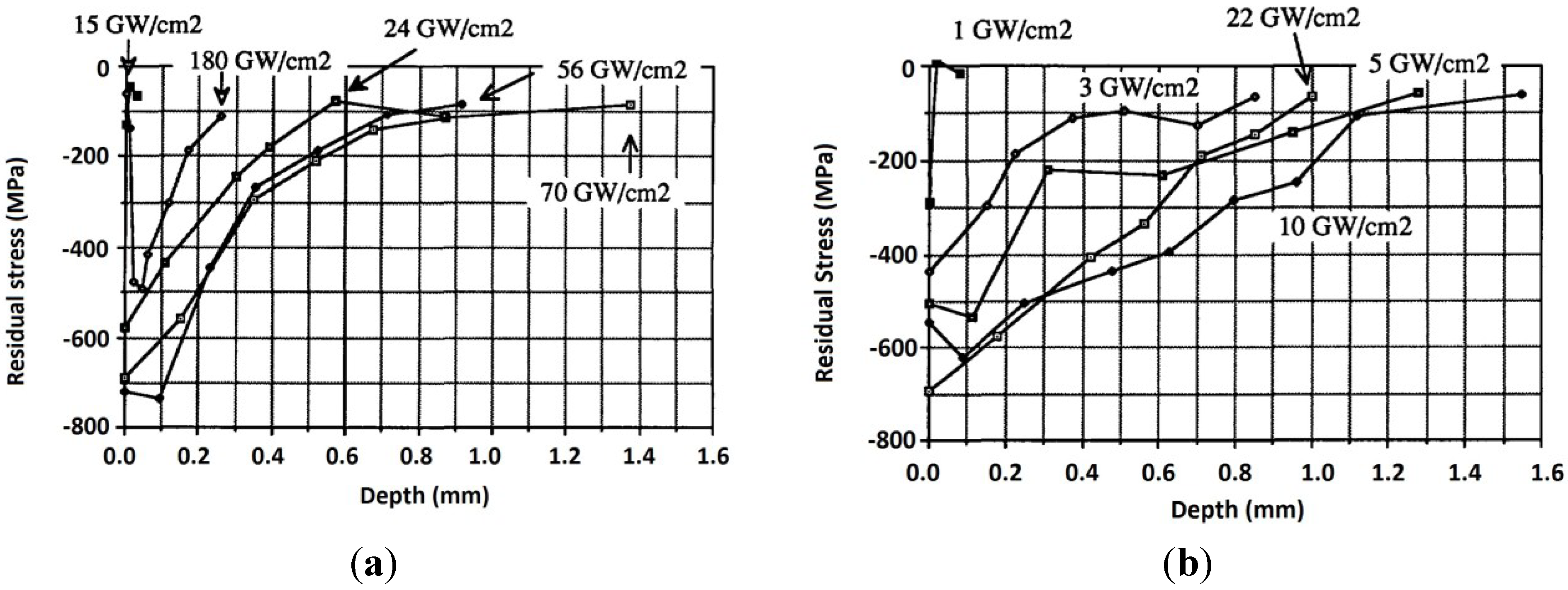
3.1.4. Residual Stress and Laser Power Density
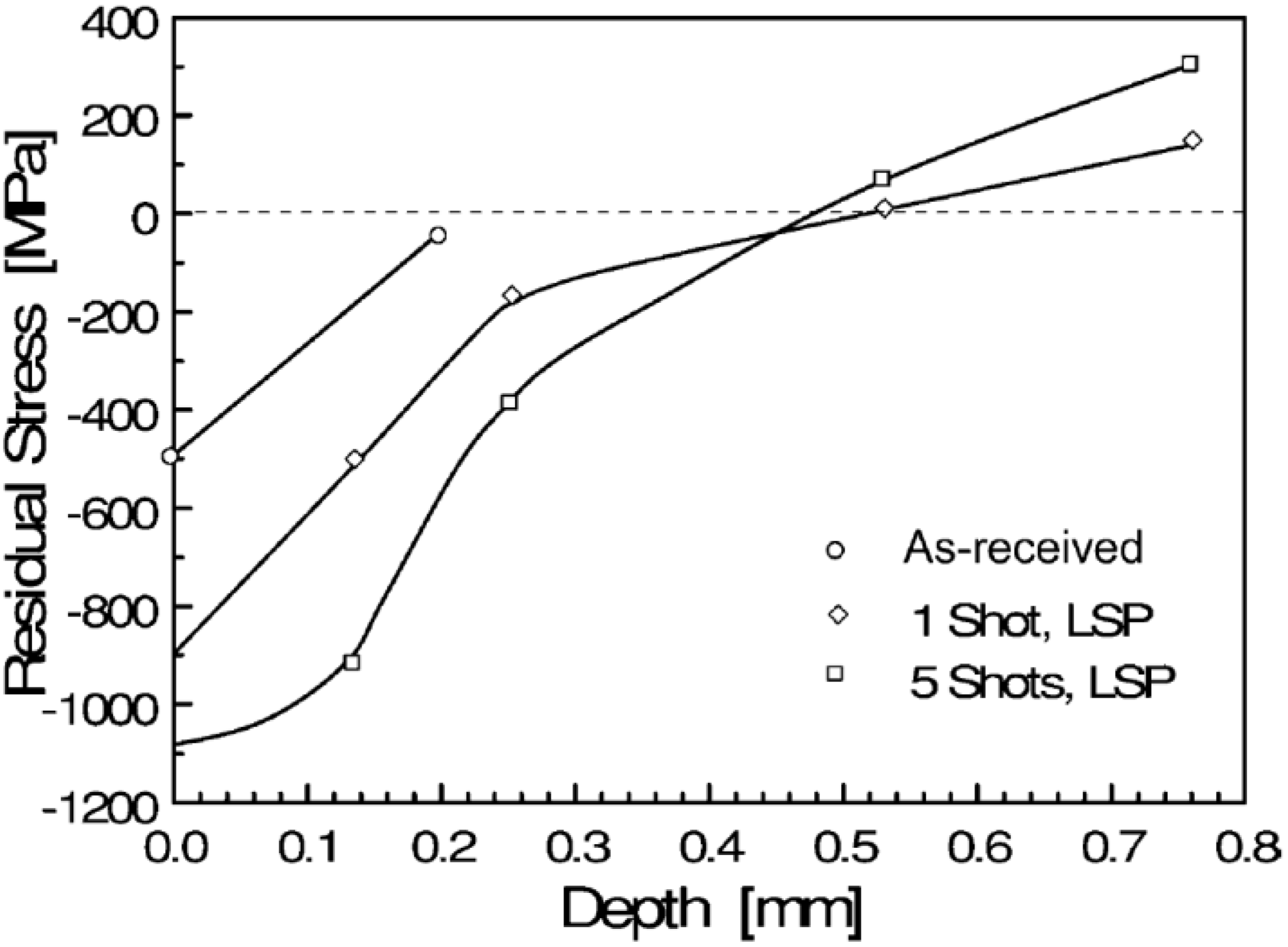
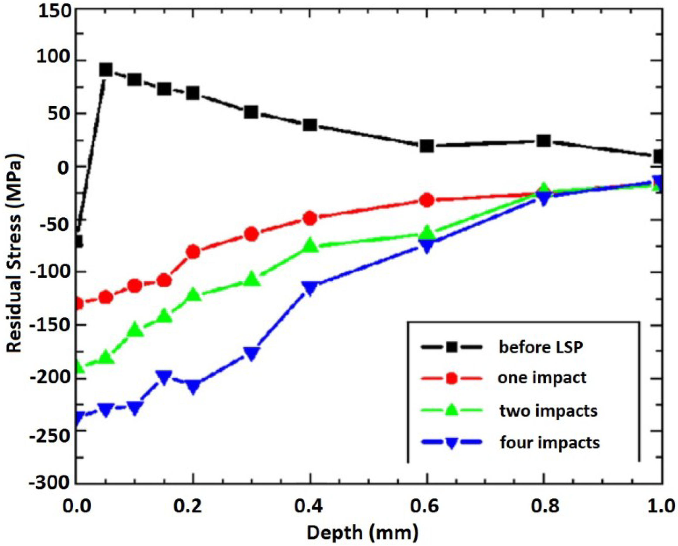
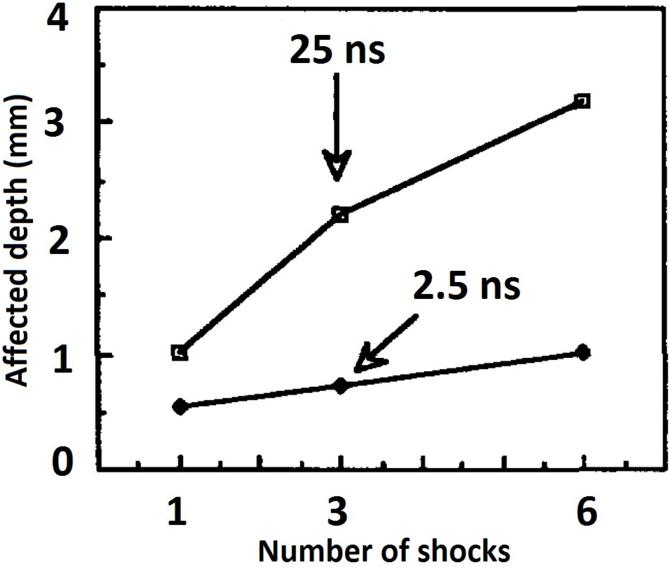
3.1.5. Residual Stress and Multiple Laser Shocks and Overlaps


3.1.6. Residual Stress and Specimen Thickness


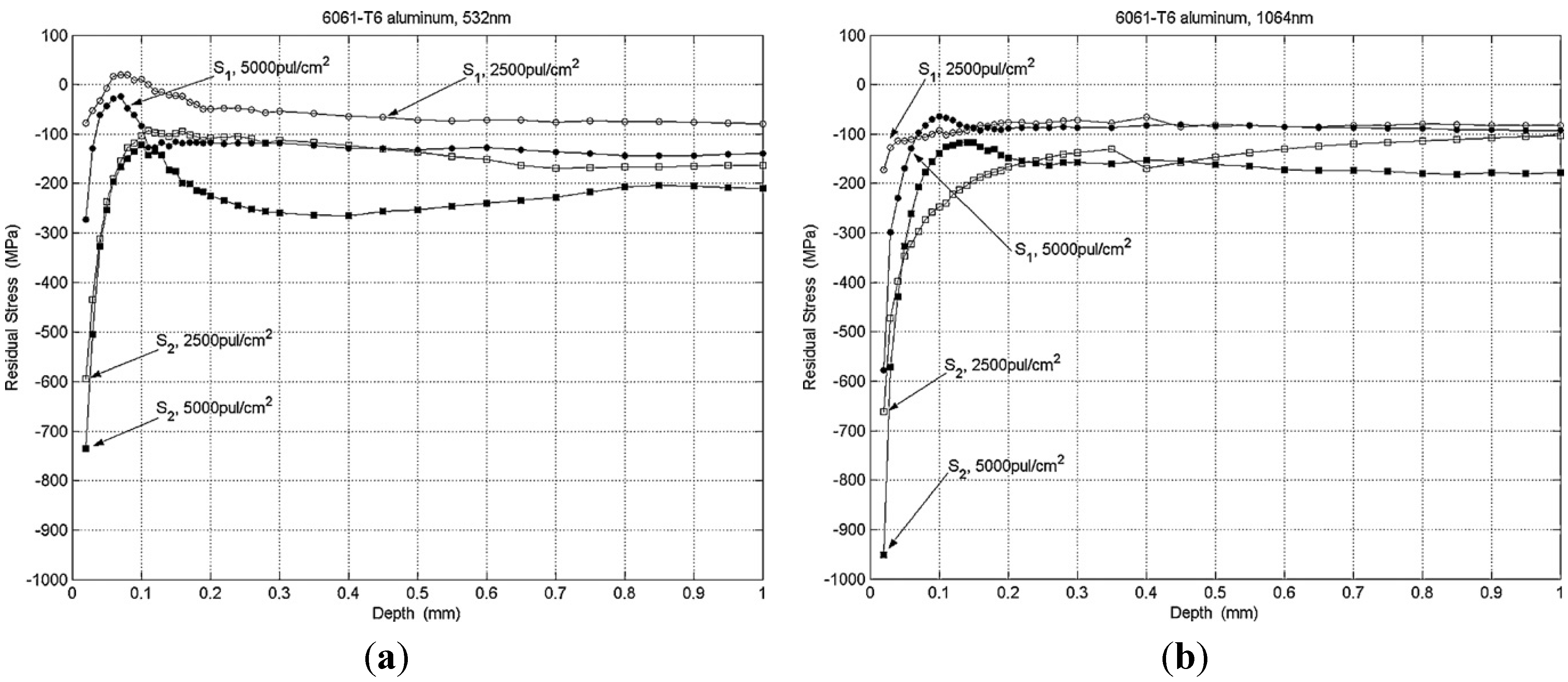
3.1.7. Residual Stress and Wavelength
3.1.8. Residual Stress and Pulse Duration

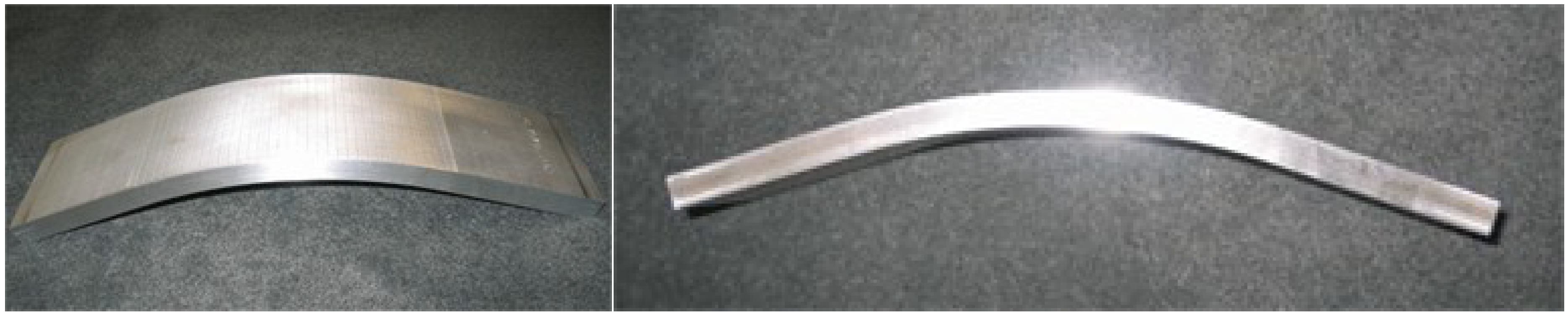
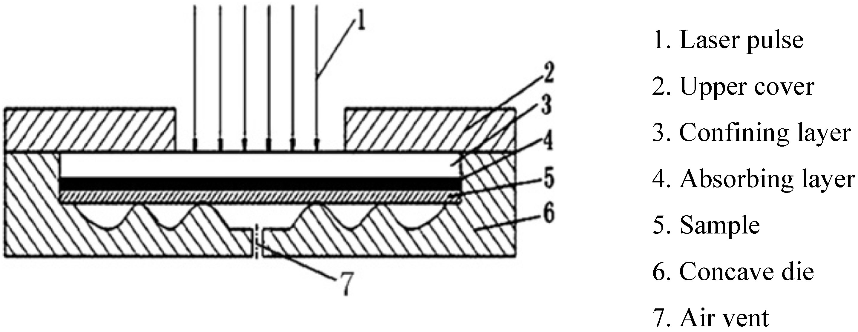
3.1.9. Residual Stress and Geometry

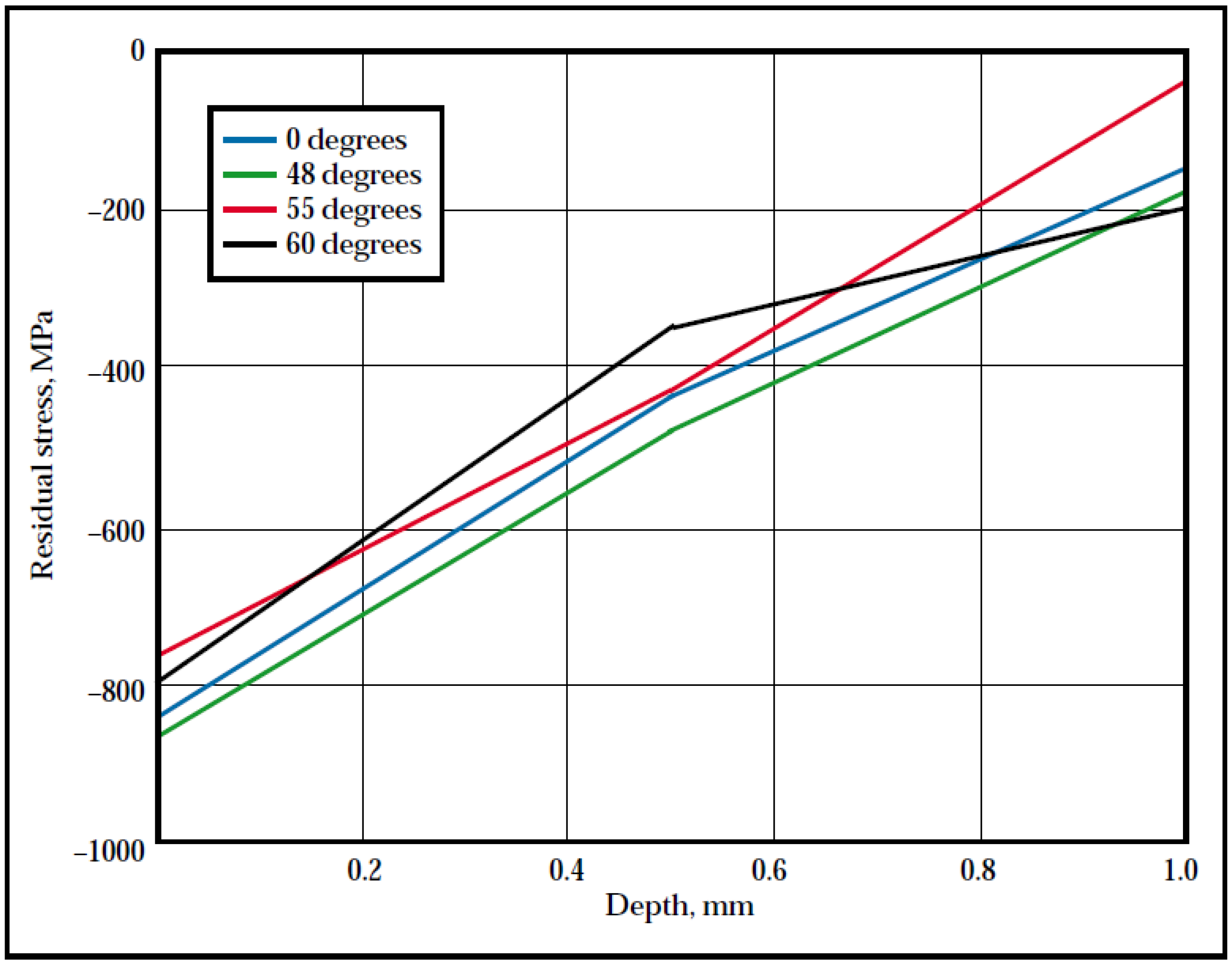
3.1.10. Residual Stress and Laser Incidence Angle
3.2. Surface Roughness
| Material | Ra (µm) arithmetic mean values | |||
|---|---|---|---|---|
| Baseline | LSP | SP | Reference | |
| A356 | 0.70 | 1.10 | 5.80 | Peyre et al. [76] |
| AA7075 | 0.60 | 1.30 | 5.70 | Peyre et al. [76] |
| 316L SS | 0.05 | 1.15 | 1.40 | Peyre et al. [8] |
| Ti-6Al-4V | 0.04 | 0.20 | 1.40 | Liu and Hill [96] |
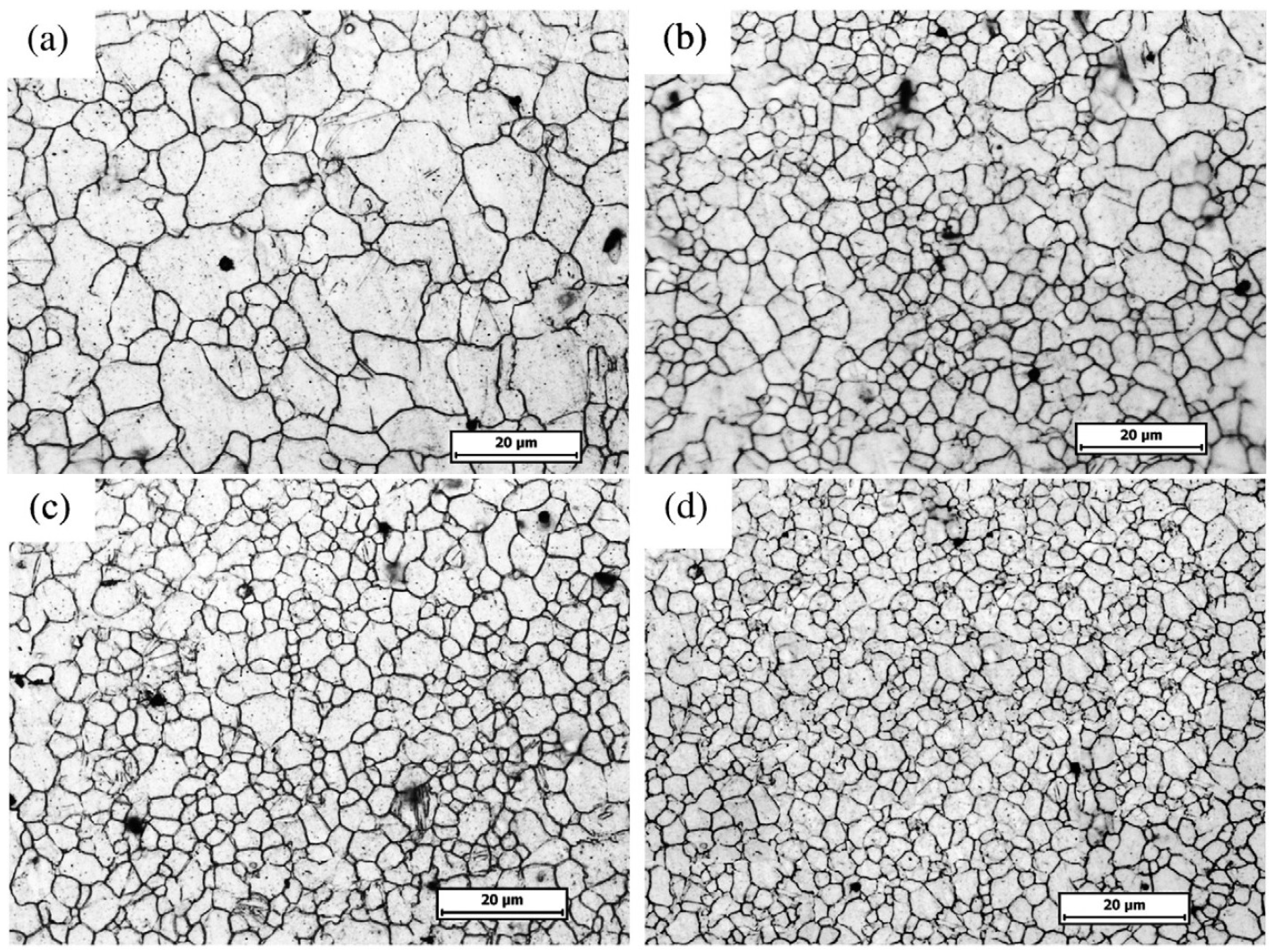
3.3. Microstructure

3.4. Mechanical Properties
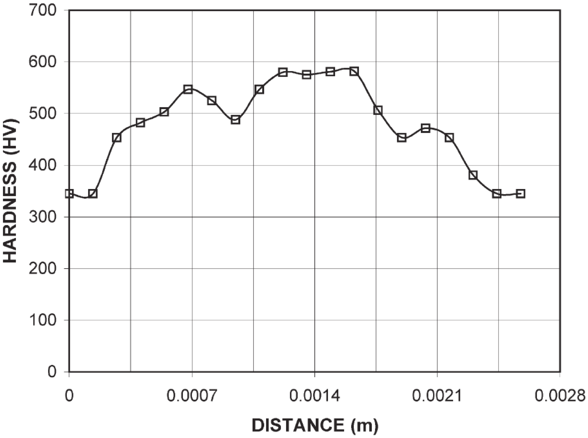
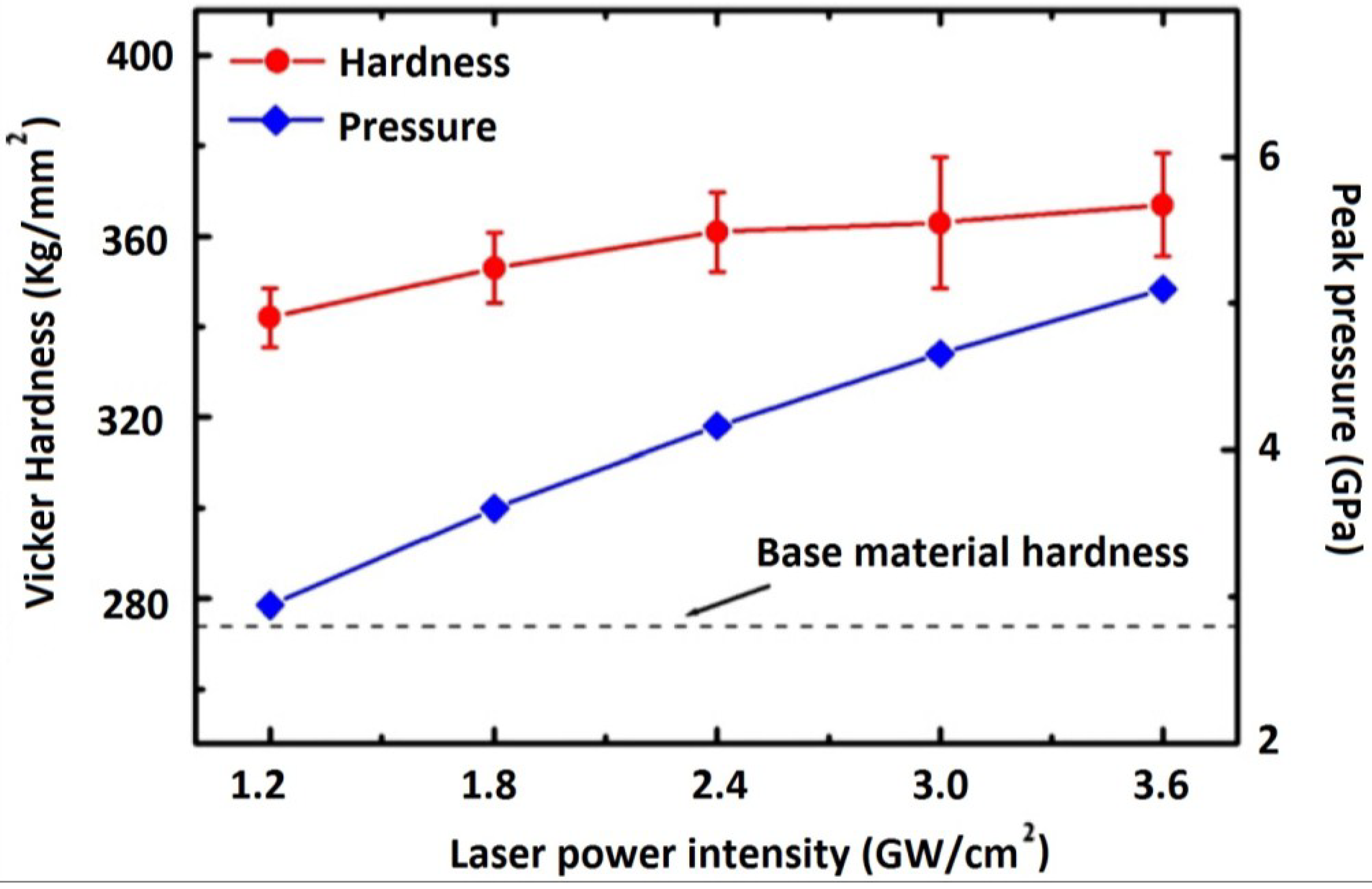
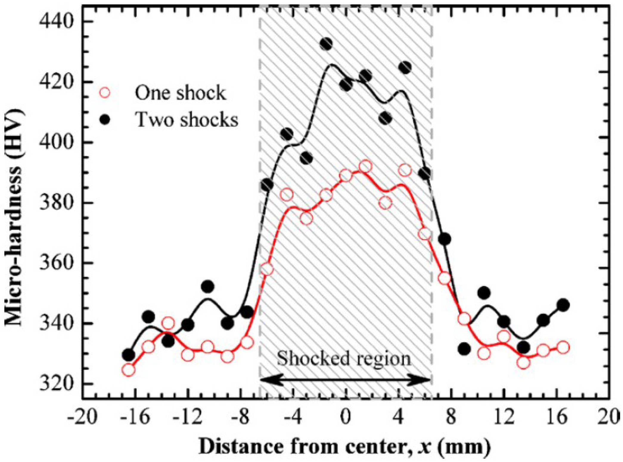
3.4.1. Hardness, Elastic Modulus and Yield Strength

| Figure (Reference) | HV for one shock | HV for two shocks | ||||
|---|---|---|---|---|---|---|
| Minimum | Maximum | ΔHV | Minimum | Maximum | ΔHV | |
| Figure 15 [93] | 350 | 580 | 230 | - | - | - |
| Figure 14 [53] | 360 | 395 | 35 | 385 | 425 | 40 |

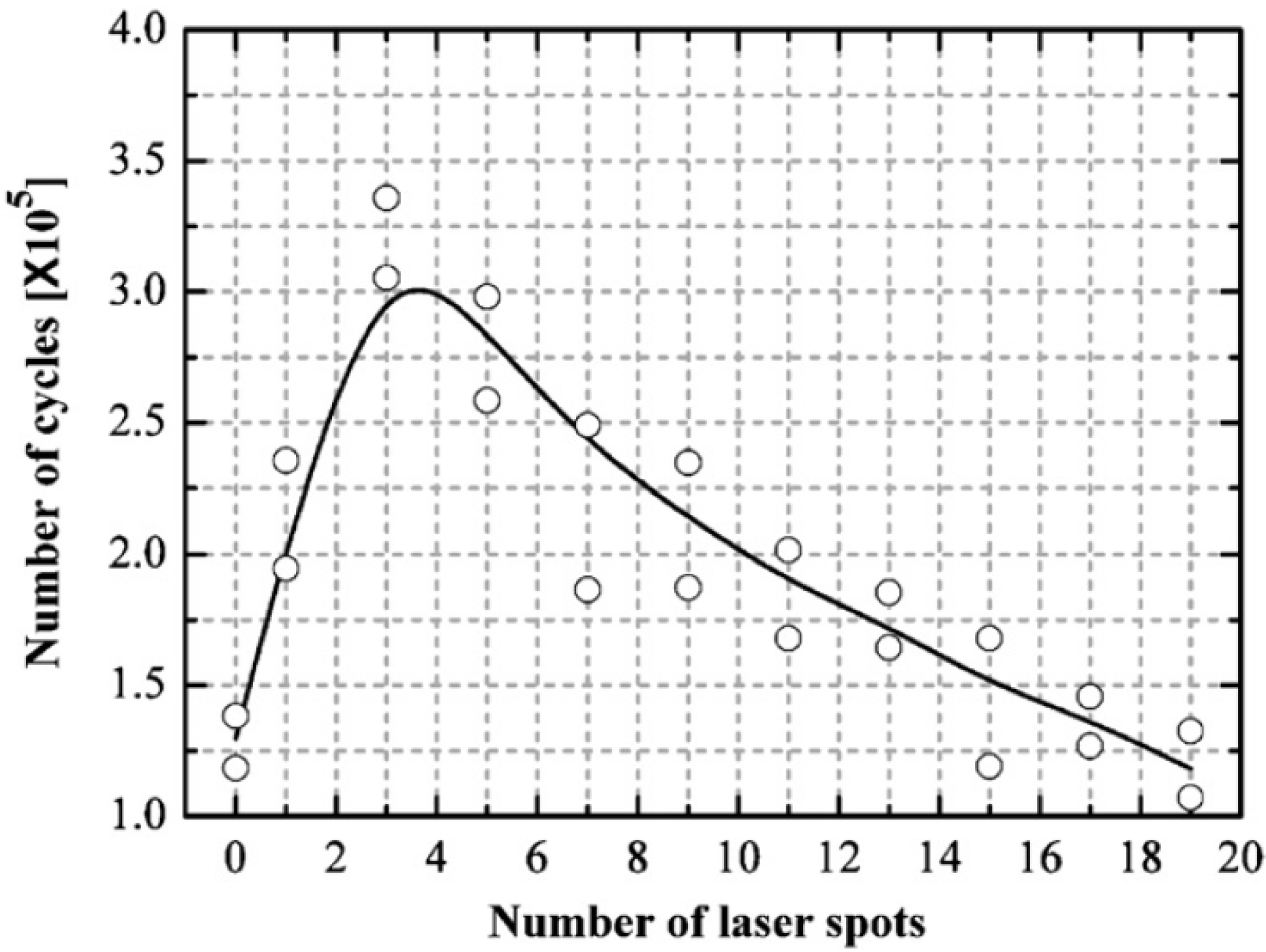
3.4.2. Fatigue Life


3.4.3. Fretting Fatigue Life
3.5. Corrosion and Stress Corrosion Cracking (SCC) Behavior
3.5.1. Corrosion Resistance Behavior
3.5.2. Stress Corrosion Cracking (SCC)

3.6. Residual Stress Relaxation and Stability

4. Applications of Laser Shock Peening: Present and Future Status


5. Challenges for the LSP Process
6. Summary
Acknowledgments
Author Contributions
Conflicts of Interest
References
- Fairand, B.P.; Clauer, A.H. Laser generation of high-amplitude stress waves in materials. J. Appl. Phys. 1979, 50, 1497–1502. [Google Scholar] [CrossRef]
- Fairand, B.P.; Wilcox, B.A.; Gallagher, W.J.; Williams, D.N. Laser shock-induced microstructural and mechanical property changes in 7075 aluminum. J. Appl. Phys. 1972, 43, 3893–3895. [Google Scholar] [CrossRef]
- Clauer, A.H.; Fairand, B.P.; Wilcox, B.A. Laser shock hardening of weld zones in aluminum alloys. Metall. Trans. A 1977, 8, 1871–1876. [Google Scholar] [CrossRef]
- Clauer, A.H.; Fairand, B.P.; Wilcox, B.A. Pulsed laser induced deformation in an Fe-3%wt Si alloy. Metall. Trans. A 1977, 8, 119–125. [Google Scholar] [CrossRef]
- Fairand, A.H.; Clauer, B.P. Interaction of laser-induced stress waves with metals. In Proceedings of the ASM Conference Applications of Lasers in Materials Processing, Washington, DC, USA, 18–20 April 1979; ASM International: Materials Park, OH, USA, 1979. [Google Scholar]
- Montross, C.; Wei, T.; Ye, L.; Clark, G.; Mai, Y. Laser shock processing and its effects on microstructure and properties of metal alloys: A review. Int. J. Fatigue 2006, 24, 1021–1036. [Google Scholar] [CrossRef]
- Peyre, P.; Fabbaro, R. Laser shock processing: A review of the physics and applications. Opt. Quant. Electron. 1995, 27, 1213–1229. [Google Scholar]
- Peyre, P.; Scherpereel, X.; Berthe, L.; Carboni, C.; Fabbro, R.; Béranger, G.; Lemaitre, C. Surface modifications induced in 316 L steel by laser peening and shot-peening. Influence on pitting corrosion resistance. Mater. Sci. Eng. A 2000, 280, 294–302. [Google Scholar] [CrossRef]
- Peyre, R.; Scherpereel, P.; Berthe, X.; Fabbro, L. Current trends in laser shock processing. Surf. Eng. 1998, 14, 377–380. [Google Scholar] [CrossRef]
- Clauer, A. A historical perspective on laser shock peening. Met. Finish. News 2009, 10, 5–6. [Google Scholar]
- Ruschau, J.; John, R.; Thompson, S.R.; Nicholas, T. Fatigue crack nucleation and growth rate behavior of laser shock peened titanium. Int. J. Fatigue 1999, 21, 199–209. [Google Scholar] [CrossRef]
- Martinez, S.A.; Sathish, S.; Blodgett, M.P.; Shepard, M.J. Residual stress distribution on surface-treated Ti-6AI-4V by X-ray diffraction. Exp. Mech. 2003, 43, 141–147. [Google Scholar] [CrossRef]
- Cao, Z.; Xu, H.; Zou, S.; Che, Z. Investigation of surface integrity on TC17 titanium alloy treated by square-spot laser shock peening. Chin. J. Aeronaut. 2012, 25, 650–656. [Google Scholar] [CrossRef]
- Vaccari, J. Laser shocking extends fatigue life. Am. Mach. 1992, 6, 21–23. [Google Scholar]
- Mannava, S. On the Fly Laser Shock Peening-General Electric Company. U.S. Patent 5,756,965, 26 May 1998. [Google Scholar]
- Mordyuk, B.N.; Prokopenko, G.I. Fatigue life improvement of α-titanium by novel ultrasonically assisted technique. Mater. Sci. Eng. A 2006, 437, 396–405. [Google Scholar] [CrossRef]
- Hou, L.; Wang, D.; Zhang, Y. Investigation of the fatigue behaviour of the welded joints treated by TIG dressing and ultrasonic peening under variable-amplitude load. Int. J. Fatigue 2005, 27, 95–101. [Google Scholar] [CrossRef]
- Xing, Y.M.; Lu, J. An experimental study of residual stress induced by ultrasonic shot peening. J. Mater. Process. Technol. 2004, 152, 56–61. [Google Scholar] [CrossRef]
- Abdullah, A.; Malaki, M.; Eskandari, A. Strength enhancement of the welded structures by ultrasonic peening. Mater. Des. 2012, 38, 7–18. [Google Scholar] [CrossRef]
- Mordyuk, B.N.; Iefimov, M.O.; Prokopenko, G.I.; Golub, T.V.; Danylenko, M.I. Structure, microhardness and damping characteristics of Al matrix composite reinforced with AlCuFe or Ti using ultrasonic impact peening. Surf. Coat. Technol. 2010, 204, 1590–1598. [Google Scholar] [CrossRef]
- Abramov, V.O.; Abramov, O.V.; Sommer, F.; Gradov, O.M.; Smirnov, O.M. Surface hardening of metals by ultrasonically accelerated small metal balls. Ultrasonics 1998, 36, 1013–1019. [Google Scholar] [CrossRef]
- Liu, G.; Lu, J.; Lu, K. Surface nanocrystallization of 316 L stainless steel induced by ultrasonic shot peening. Mater. Sci. Eng. A 2000, 286, 91–95. [Google Scholar] [CrossRef]
- Sandá, A.; García Navas, V.; Gonzalo, O. Surface state of Inconel 718 ultrasonic shot peened: Effect of processing time, material and quantity of shot balls and distance from radiating surface to sample. Mater. Des. 2011, 32, 2213–2220. [Google Scholar] [CrossRef]
- Tao, N.; Sui, M.; Lu, J.; Lua, K. Surface nanocrystallization of iron induced by ultrasonic shot peening. Nanostruct. Mater. 1999, 11, 433–440. [Google Scholar] [CrossRef]
- Yin, D.; Wang, D.; Jing, H.; Huo, L. The effects of ultrasonic peening treatment on the ultra-long life fatigue behavior of welded joints. Mater. Des. 2010, 31, 3299–3307. [Google Scholar] [CrossRef]
- Mordyuk, B.N.; Prokopenko, G.I. Ultrasonic impact peening for the surface properties’ managemen. J. Sound Vib. 2007, 308, 855–866. [Google Scholar] [CrossRef]
- Liao, M.; Chen, W.R.; Bellinger, N.C. Effects of ultrasonic impact treatment on fatigue behavior of naturally exfoliated aluminum alloys. Int. J. Fatigue 2008, 30, 717–726. [Google Scholar] [CrossRef]
- Roy, S.; Fisher, J. Enhancing fatigue strength by ultrasonic impact treatment. Steel Struct. 2005, 5, 241–252. [Google Scholar]
- Vilhauer, B.; Bennett, C.R.; Matamoros, A.B.; Rolfe, S.T. Fatigue behavior of welded coverplates treated with Ultrasonic Impact Treatment and bolting. Eng. Struct. 2012, 34, 163–172. [Google Scholar] [CrossRef]
- Roy, S. Fatigue resistance of welded details enhanced by ultrasonic impact treatment (UIT). Int. J. Fatigue 2003, 25, 1239–1247. [Google Scholar] [CrossRef]
- Berg-Pollack, A.; Voellmecke, F.J.; Sonsino, C.M. Fatigue strength improvement by ultrasonic impact treatment of highly stressed spokes of cast aluminium wheels. Int. J. Fatigue 2011, 33, 513–518. [Google Scholar] [CrossRef]
- Lihavainen, V.M.; Marquis, G.; Statnikov, E.S. Fatigue strength of a longitudinal attachment improved by ultrasonic impact treatment. Weld. World 2004, 48, 67–73. [Google Scholar] [CrossRef]
- Yang, X.; Ling, X.; Zhou, J. Optimization of the fatigue resistance of AISI304 stainless steel by ultrasonic impact treatment. Int. J. Fatigue 2014, 61, 28–38. [Google Scholar] [CrossRef]
- Statnikov, E.S.; Korolkov, O.V.; Vityazev, V.N. Physics and mechanism of ultrasonic impact. Ultrasonics 2006, 44, 533–538. [Google Scholar] [CrossRef]
- Statnikov, E. Physics and mechanism of ultrasonic impact treatment. Int. Inst. Weld. 2004, 13, 1–30. [Google Scholar]
- An, X.; Rodopoulos, C.A.; Statnikov, E.S.; Vitazev, V.N.; Korolkov, O.V. Study of the surface nanocrystallization induced by the esonix ultrasonic impact treatment on the near-surface of 2024-T351 aluminum alloy. J. Mater. Eng. Perform. 2006, 15, 355–364. [Google Scholar] [CrossRef]
- Yang, X.; Zhou, J.; Ling, X. Study on plastic damage of AISI 304 stainless steel induced by ultrasonic impact treatment. Mater. Des. 2012, 36, 477–481. [Google Scholar] [CrossRef]
- Fan, Z.; Xu, H.; Li, D.; Zhang, L.; Liao, L. Surface nanocrystallization of 35# type carbon steel induced by ultrasonic impact treatment (UIT). Procedia Eng. 2012, 27, 1718–1722. [Google Scholar] [CrossRef]
- Galtier, A.; Statnikov, E.S. The influence of ultrasonic impact treatment on fatigue behaviour of welded joints in high-strength steel. Weld. World 2004, 48, 61–66. [Google Scholar] [CrossRef]
- Günther, H.; Kuhlmann, U.; Durr, A. Rehabilitation of welded joints by ultrasonic impact treatment (UIT). In Proceedings of the IABSE Symposium Report, Lisbon, Portugal, 14–17 September 2005; International Association for Bridge and Structural Engineering: Lisbon, Portugal, 2005; pp. 1–7. [Google Scholar]
- LSP Technologies. Surface enhancement technologies. Available online: http://www.lsptechnologies.com (accessed on 5 May 2014).
- Mannava, S.; Cowie, W.D. Technique to Prevent or Divert Cracks-General Electric Company. U.S. Patent 5,569,018, 29 October 1996. [Google Scholar]
- Luo, K.Y.; Wang, C.Y.; Li, Y.M.; Luo, M.; Huang, S.; Hua, X.J.; Lu, J.Z. Effects of laser shock peening and groove spacing on the wear behavior of non-smooth surface fabricated by laser surface texturing. Appl. Surf. Sci. 2014, 313, 600–606. [Google Scholar] [CrossRef]
- Dane, C.; Hackel, L.; Daly, J.; Harirson, J. Laser peening of metals enabling laser technology. Adv. Mater. Process. 1997, 13–27. [Google Scholar]
- Mannava, S.; Ferrigno, S. Laser Shock Peening for Gas Turbine Engine Vane Repair-General Electric Company. U.S. Patent 5,675,892, 14 October 1997. [Google Scholar]
- Mannava, S.; Ferrigno, S.; Cowie, W.D. Laser Shock Peening for Gas Turbine Engine Weld Repair-General Electric Company. U.S. Patent 5,846,057, 8 December 1998. [Google Scholar]
- Metal Improvement Company: Shot peening. Available online: http://www.metalimprovement.com/ (accessed on 21 October 2013).
- Dane, C.B.; Harris, F.; Lao, E.; Rankin, J.; Hurd, R. Advanced beam delivery for mobile laser peening. In Proceedings of the 2nd International Conference on Laser Peening, San Francisco, CA, USA, 19 April 2010; Metal Improvement Company: Paramus, NJ, USA, 2010. [Google Scholar]
- Clauer, A.H.; Holbrook, J.H.; Fairand, B.P. Effects of laser induced shock waves on metals. In Shock Waves and High Strain Rate Phenomena in Metals; Plenum Publishing Corporation: New York, NY, USA, 1981; pp. 675–703. [Google Scholar]
- Clauer, A.H. Laser shock of peening for fatigue resistance. In Surface Performance of Titanium; The Minerals, Metals and Materials Society (TMS): Warrendale, PA, USA, 1996; pp. 217–230. [Google Scholar]
- Fabbro, R.; Peyre, P.; Berthe, L.; Scherpereel, X. Physics and applications of laser-shock processing. J. Laser Appl. 1998, 10, 265–279. [Google Scholar] [CrossRef]
- Kruusing, A. Underwater and water-assisted laser processing: Part 1-general features, steam cleaning and shock processing. Opt. Lasers Eng. 2004, 41, 307–327. [Google Scholar] [CrossRef]
- Zhang, X.C.; Zhang, Y.K.; Lu, J.Z.; Xuan, F.Z.; Wang, Z.D.; Tu, S.T. Improvement of fatigue life of Ti-6Al-4V alloy by laser shock peening. Mater. Sci. Eng. A 2010, 527, 3411–3415. [Google Scholar] [CrossRef]
- Guo, Y.; Caslaru, R. Fabrication and characterization of micro dent arrays produced by laser shock peening on titanium Ti-6Al-4V surfaces. J. Mater. Process. Technol. 2011, 211, 729–736. [Google Scholar] [CrossRef]
- Brar, N.S.; Hopkins, A.; Laber, M.W. Laser shock peening of titanium 6–4 alloy. AIP Conf. Proc. 2000, 505, 435–438. [Google Scholar]
- Tani, G.; Orazi, L.; Fortunato, A.; Ascari, A.; Campana, G. Warm laser shock peening—New developments and process optimization. CIRP Ann. Manuf. Tech. 2011, 60, 219–222. [Google Scholar] [CrossRef]
- Rubio-González, C.; Gomez-Rosas, G.; Ocaña, J.; Molpeceres, C.; Banderas, A.; Porro, J.; Morales, M. Effect of an absorbent overlay on the residual stress field induced by laser shock processing on aluminum samples. Appl. Surf. Sci. 2006, 252, 6201–6205. [Google Scholar] [CrossRef]
- Golden, J.; Hutson, A.; Sundaram, V.; Arps, J. Effect of surface treatments on fretting fatigue of Ti-6Al-4V. Int. J. Fatigue 2007, 29, 1302–1310. [Google Scholar] [CrossRef]
- Chen, H.; Claudet, A.; Zaleski, T.; Dane, C.; Lane, L.; Hackel, L.; Harris, F.; Halpin, J. Laser process form thick, curved metal parts. Sci. Technol. Rev. 2003, 10, 16–17. [Google Scholar]
- Hatamleh, O. A comprehensive investigation on the effects of laser and shot peening on fatigue crack growth in friction stir welded AA 2195 joints. Int. J. Fatigue 2009, 31, 974–988. [Google Scholar] [CrossRef]
- Hatamleh, O.; DeWald, A. An investigation of the peening effects on the residual stresses in friction stir welded 2195 and 7075 aluminum alloy joints. J. Mater. Process. Technol. 2009, 209, 4822–4829. [Google Scholar] [CrossRef]
- Montross, C.; Florea, V.; Swain, M. The influence of coatings on subsurface mechanical properties of laser peened 2011-T3 aluminum. J. Mater. Sci. 2011, 36, 1801–1807. [Google Scholar] [CrossRef]
- Cheng, G.J.; Shehadeh, M.A. Dislocation behavior in silicon crystal induced by laser shock peening-A multiscale simulation approach. Scripta Mater. 2005, 53, 1013–1018. [Google Scholar] [CrossRef]
- Hong, X.; Wang, S.; Guo, D.; Wu, H.; Wang, J.; Dai, Y.; Xia, X.; Xie, Y. Confining medium and absorptive overlay: Their effects on a laser-induced shock wave. Opt. Lasers Eng. 1998, 29, 447–455. [Google Scholar] [CrossRef]
- Zhou, Z.; Bhamare, S.; Ramakrishnan, G.; Mannava, S.R.; Langer, K.; Wen, Y.; Qian, D.; Vasudevan, V.K. Thermal relaxation of residual stress in laser shock peened Ti-6Al-4V alloy. Surf. Coat. Technol. 2012, 206, 4619–4627. [Google Scholar] [CrossRef]
- Cao, Y.; Shin, Y.; Wu, B. Parametric study on single shot and overlapping laser shock peening on various metals via modeling and experiments. J. Manuf. Sci. Eng. 2010, 132, 061010–061017. [Google Scholar] [CrossRef]
- Thareja, R.; Shukla, S. Synthesis and characterization of zinc oxide nanoparticles by laser ablation of zinc in liquid. Appl. Surf. Sci. 2007, 253, 8889–8895. [Google Scholar] [CrossRef]
- Ling, X.; Peng, W.; Ma, G. Influence of laser peening parameters on residual stress field of 304 stainless steel. J. Press. Vessel Technol. 2008, 130, 021201. [Google Scholar] [CrossRef]
- Ye, C.; Suslov, S.; Kim, B.J.; Stach, E.A.; Cheng, G.J. Fatigue performance improvement in AISI 4140 steel by dynamic strain aging and dynamic precipitation during warm laser shock peening. Acta Mater. 2011, 59, 1014–1025. [Google Scholar] [CrossRef]
- Jiang, Y.; Huang, Y.; Jin, H.; Gu, Y.; Ren, A.; Huang, L.; Qian, X. Research on precision control of sheet metal forming by laser shock waves with semi-die. Opt. Lasers Eng. 2013, 45, 598–604. [Google Scholar] [CrossRef]
- Srinivasan, S.; Garcia, D.B.; Gean, M.C.; Murthy, H.; Farris, T.N. Fretting fatigue of laser shock peened Ti-6Al-4V. Tribol. Int. 2009, 42, 1324–1329. [Google Scholar] [CrossRef]
- Cao, Z.; Che, Z.; Zou, S.; Fei, Q. Numerical simulation of residual stress field induced by laser shock processing with square spot. J. Shanghai Univ. 2011, 15, 553–556. [Google Scholar] [CrossRef]
- Kim, J.H.; Kim, Y.J.; Kim, J.S. Effects of laser source geometry on laser shock peening residual stress. Korean Soc. Mech. Eng. 2012, 36, 609–615. [Google Scholar] [CrossRef]
- Rhode, R.; Johnson, J. Dynamic deformation twinning in shock loaded iron. J. Appl. Phys. 1971, 42, 4171–4182. [Google Scholar] [CrossRef]
- Hong, Z.; Chengye, Y. Laser shock processing of 2024-T62 aluminum alloy. Mater. Sci. Eng. A 1998, 257, 322–327. [Google Scholar] [CrossRef]
- Peyre, P.; Fabbro, R.; Merrien, P.; Lieurade, H. Laser shock processing of aluminium alloys. Application to high cycle fatigue behaviour. Mater. Sci. Eng. A 1996, 210, 102–113. [Google Scholar] [CrossRef]
- Yang, C.; Hodgson, P.D.; Liu, Q.; Ye, L. Geometrical effects on residual stresses in 7050-T7451 aluminum alloy rods subject to laser shock peening. J. Mater. Process. Technol. 2008, 201, 303–309. [Google Scholar] [CrossRef]
- Laser Research Center, Lidaris Ltd, Vilnius University. Available online: http://lidaris.com/glossary-2/fluence/ (accessed on 10 October 2013).
- Sealy, M.P.; Guo, Y.B. Surface integrity and process mechanics of laser shock peening of novel biodegradable magnesium-calcium (Mg-Ca) alloy. J. Mech. Behav. Biomed. Mater. 2010, 3, 488–496. [Google Scholar] [CrossRef] [PubMed]
- Bolis, C.; Berthe, L.; Boustie, M.; Arrigoni, M.; Barradas, S.; Jeandin, M. Physical approach to adhesion testing using laser-driven shock waves. J. Phys. D Appl. Phys. 2007, 40, 3155–3163. [Google Scholar] [CrossRef]
- Mordyuk, B.N.; Milman, Y.V.; Iefimov, M.O.; Prokopenko, G.I.; Silberschmidt, V.V.; Danylenko, M.I.; Kotko, A.V. Characterization of ultrasonically peened and laser shock peened surface layers of AISI 321 stainless steel. Surf. Coat. Technol. 2008, 202, 4875–4883. [Google Scholar] [CrossRef]
- Cellard, C.; Retraint, D.; François, M.; Rouhaud, E.; le Saunier, D. Laser shock peening of Ti-17 titanium alloy: Influence of process parameters. Mater. Sci. Eng. A 2012, 532, 362–372. [Google Scholar] [CrossRef]
- Tan, Y.; Wu, G.; Yang, J.; Pan, T. Laser shock peening on fatigue crack growth behaviour. Fatigue Fract. Eng. Mater. Struct. 2004, 27, 649–656. [Google Scholar] [CrossRef]
- Liao, Y.; Suslov, S.; Ye, C.; Cheng, G. The mechanisms of thermal engineered laser shock peening for enhanced fatigue performance. Acta Mater. 2012, 60, 4997–5009. [Google Scholar] [CrossRef]
- Kalainathan, S.; Sathyajith, S.; Swaroop, S. Effect of laser shot peening without coating on the surface properties and corrosion behavior of 316 L steel. Opt. Lasers Eng. 2012, 50, 1740–1745. [Google Scholar] [CrossRef]
- Rubio-González, C.; Felix-Martinez, C.; Gomez-Rosas, G.; Ocaña, J.L.; Morales, M.; Porro, J.A. Effect of laser shock processing on fatigue crack growth of duplex stainless steel. Mater. Sci. Eng. A 2011, 528, 914–919. [Google Scholar] [CrossRef]
- Cheng, G.J.; Pirzada, D.; Ming, Z. Microstructure and mechanical property characterizations of metal foil after microscale laser dynamic forming. J. Appl. Phys. 2007, 101, 063108:1–063108:7. [Google Scholar]
- Hill, M.R.; Dewald, A.T.; Rankin, J.E.; Lee, M.J. Measurement of laser peening residual stresses. J. Mater. Sci. Technol. 2005, 21, 3–9. [Google Scholar] [CrossRef]
- Bugayev, A.A.; Gupta, M.C.; Payne, R. Laser processing of inconel 600 and surface structure. Opt. Lasers Eng. 2006, 44, 102–111. [Google Scholar] [CrossRef]
- Zhang, Y.; You, J.; Lu, J.; Cui, C.; Jiang, Y.; Ren, X. Effects of laser shock processing on stress corrosion cracking susceptibility of AZ31B magnesium alloy. Surf. Coat. Technol. 2010, 204, 3947–3953. [Google Scholar] [CrossRef]
- Wang, F.; Yao, Z.; Deng, Q. Experimental study on laser shock processing of brass. J. Univ. Sci. Technol. Beijing Miner. Metall. Mater. 2007, 14, 529–532. [Google Scholar]
- Forget, P.; Strudel, J.L.; Jeandin, M.; Lu, J.; Castex, L. Laser shock surface treatment of Ni-based superalloys. Mater. Manuf. Process. 1990, 5, 501–528. [Google Scholar] [CrossRef]
- Yilbas, B.S.; Gondal, M.A.; Arif, A.M.; Shuja, S.Z. Laser shock processing of Ti-6Al-4V alloy. Proc. Instn. Mech. Eng. 2004, 218, 473–483. [Google Scholar] [CrossRef]
- Zabeen, S.; Preuss, M.; Withers, P.J. Residual stresses caused by head-on and 45° foreign object damage for a laser shock peened Ti-6Al-4V alloy aerofoil. Mater. Sci. Eng. A 2013, 560, 518–527. [Google Scholar] [CrossRef]
- Rozmus-Górnikowska, M. Surface modifications of a Ti-6Al-4V alloy by a laser shock processing. Acta Phys. Pol. A 2010, 117, 808–811. [Google Scholar]
- Liu, K.K.; Hill, M.R. The effects of laser peening and shot peening on fretting fatigue in Ti-6Al-4V coupons. Tribol. Int. 2009, 42, 1250–1262. [Google Scholar] [CrossRef]
- Altenberger, I.; Nalla, R.K.; Sano, Y.; Wagner, L.; Ritchie, R.O. On the effect of deep-rolling and laser-peening on the stress-controlled low- and high-cycle fatigue behavior of Ti-6Al-4V at elevated temperatures up to 550 °C. Int. J. Fatigue 2012, 44, 292–302. [Google Scholar] [CrossRef]
- Brockman, R.A.; Braisted, W.R.; Olson, S.E.; Tenaglia, R.D.; Clauer, A.H.; Langer, K.; Shepard, M.J. Prediction and characterization of residual stresses from laser shock peening. Int. J. Fatigue 2012, 36, 96–108. [Google Scholar] [CrossRef]
- Dane, C.; Hackel, L.; Daly, J. Shot peening with laser. Adv. Mater. Process. 1998, 153, 37–48. [Google Scholar]
- Wagner, L.; Mhaede, M.; Wollmann, M.; Altenberger, I.; Sano, Y. Surface layer properties and fatigue behavior in Al 7075-T73 and Ti-6Al-4V: Comparing results after laser peening, shot peening and ball-burnishing. Int. J. Struct. Integr. 2011, 2, 185–199. [Google Scholar] [CrossRef]
- Ye, C.; Liao, Y.; Cheng, G.J. Warm laser shock peening driven nanostructures and their effects on fatigue performance in aluminium alloy 6160. Adv. Eng. Mater. 2010, 12, 291–297. [Google Scholar]
- Trdan, U.; Grum, J. Evaluation of corrosion resistance of AA6082-T651 aluminium alloy after laser shock peening by means of cyclic polarisation and ElS methods. Corros. Sci. 2012, 59, 324–333. [Google Scholar] [CrossRef]
- Ocaña, J.L.; Molpeceres, C.; Porro, J.A.; Gómez, G.; Morales, M. Experimental assessment of the influence of irradiation parameters on surface deformation and residual stresses in laser shock processed metallic alloys. Appl. Surf. Sci. 2004, 238, 501–505. [Google Scholar] [CrossRef]
- Hatamleh, O. Effects of peening on mechanical properties in friction stir welded 2195 aluminum alloy joints. Mater. Sci. Eng. A 2008, 492, 168–176. [Google Scholar] [CrossRef]
- Trdan, U.; Porro, J.A.; Ocaña, J.L.; Grum, J. Laser shock peening without absorbent coating (LSPwC) effect on 3D surface topography and mechanical properties of 6082-T651 Al alloy. Surf. Coat. Technol. 2012, 208, 109–116. [Google Scholar] [CrossRef]
- Luo, K.; Lu, J.; Zhang, L.; Zhong, J.; Guan, H.; Qian, X. The microstructural mechanism for mechanical property of LY2 aluminum alloy after laser shock processing. Mater. Des. 2010, 31, 2599–2603. [Google Scholar] [CrossRef]
- Li, K.; Hu, Y.; Yao, Z. Experimental study of micro dimple fabrication based on laser shock processing. Opt. Laser Technol. 2013, 48, 216–225. [Google Scholar] [CrossRef]
- Amar, H.; Vignal, V.; Krawiec, H.; Josse, C.; Peyre, P.; da Silva, S.N.; Dick, L.F. Influence of the microstructure and laser shock processing (LSP) on the corrosion behaviour of the AA2050-T8 aluminium alloy. Corros. Sci. 2011, 53, 3215–3221. [Google Scholar] [CrossRef]
- Zhang, Y.K.; Ren, X.D.; Zhou, J.Z.; Lu, J.Z.; Zhou, L.C. Investigation of the stress intensity factor changing on the hole crack subject to laser shock processing. Mater. Des. 2009, 30, 2769–2773. [Google Scholar] [CrossRef]
- Vukelić, S.; Kysar, J.W.; Yao, Y.L. Grain boundary response of aluminum bicrystal under micro scale laser shock peening. Int. J. Solids Struct. 2009, 46, 3323–3335. [Google Scholar] [CrossRef]
- Gomez-Rosas, G.; Rubio-Gonzalez, C.; Ocaña, J.L.; Molpeceres, C.; Porro, J.A.; Morales, M.; Casillas, F.J. Laser shock processing of 6061-T6 Al alloy with 1064 nm and 532 nm wavelengths. Appl. Surf. Sci. 2010, 256, 5828–5831. [Google Scholar] [CrossRef]
- Yang, J.M.; Her, Y.C.; Han, N.; Clauer, A. Laser shock peening on fatigue behavior of 2024-T3 Al alloy with fastener holes and stopholes. Mater. Sci. Eng. A 2001, 298, 296–299. [Google Scholar] [CrossRef]
- Liu, Q.; Ding, K.; Ye, L.; Rey, C.; Barter, S.A.; Sharp, P.K.; Clark, G. Spallation-like phenomenon induced by laser shock peening surface treatment on 7050 aluminum alloy. In Proceedings of the Structural Integrity and Fracture International Conference (SIF'04), Brisbane, Australia, 26–29 September 2004; The University of Queensland: Brisbane, Australia, 2004; pp. 235–240. [Google Scholar]
- Peyre, P.; Berthe, L.; Scherpereel, X.; Fabbro, R. Laser-shock processing of aluminium-coated 55C1 steel in water-confinement regime, characterization and application to high-cycle fatigue behaviour. J. Mater. Sci. 1998, 3, 1421–1429. [Google Scholar] [CrossRef]
- Lu, J.; Yang, C.; Zhang, L.; Feng, A.; Jiang, Y. Mechanical properties and microstructure of bionic non-smooth stainless steel surface by laser multiple processing. J. Bionic Eng. 2009, 6, 180–185. [Google Scholar] [CrossRef]
- Yilbas, B.S.; Shuja, S.Z.; Arif, A.; Gondal, M.A. Laser-shock processing of steel. J. Mater. Process. Technol. 2003, 135, 6–17. [Google Scholar] [CrossRef]
- Luo, K.Y.; Lu, J.Z.; Zhang, Y.K.; Zhou, J.Z.; Zhang, L.F.; Dai, F.Z.; Zhang, L.; Zhong, J.W.; Cui, C.Y. Effects of laser shock processing on mechanical properties and micro-structure of ANSI 304 austenitic stainless steel. Mater. Sci. Eng. A 2011, 528, 4783–4788. [Google Scholar] [CrossRef]
- Ren, X.D.; Jiang, D.W.; Zhang, Y.K.; Zhang, T.; Guan, H.B.; Qian, X.M. Effects of laser shock processing on 00Cr12 mechanical properties in the temperature range from 25 to 600 °C. Appl. Surf. Sci. 2010, 257, 1712–1715. [Google Scholar] [CrossRef]
- Sudha, C.; Parameswaran, P.; Krishnan, R.; Dash, S.; Vijayalakshmi, M. Effect of laser shock processing on the microstructure of 304(L) austenitic stainless steel. Mater. Manuf. Process. 2010, 25, 956–964. [Google Scholar] [CrossRef]
- Hu, Y.; Gong, C.; Yao, Z.; Hu, J. Investigation on the non-homogeneity of residual stress field induced by laser shock peening. Surf. Coat. Technol. 2009, 203, 3503–3508. [Google Scholar] [CrossRef]
- Sano, Y.; Obata, M.; Yamamoto, T. Residual stress improvement of weldment by laser peening. Weld. Int. 2006, 20, 598–601. [Google Scholar] [CrossRef]
- Sano, Y.; Akita, K.; Masaki, K.; Ochi, Y.; Altenberger, I.; Scholtes, B. Laser peening without coating as a surface enhancement technology. J. Laser Micro/Nano Eng. 2006, 1, 161–166. [Google Scholar] [CrossRef]
- Yakimets, I.; Richard, C.; Béranger, G.; Peyre, P. Laser peening processing effect on mechanical and tribological properties of rolling steel 100Cr6. Wear 2004, 256, 311–320. [Google Scholar] [CrossRef]
- Berthe, L.; Fabbro, R.; Peyre, P.; Braham, C.; Le, J. Corrosion reactivity of laser-peened steel surfaces. J. Mater. Eng. Perform. 2000, 9, 656–662. [Google Scholar] [CrossRef]
- Chu, J.P.; Rigsbee, J.M.; Banas, G.; Elsayed-Ali, H.E. Laser-shock processing effects on surface microstructure and mechanical properties of low carbon steel. Mater. Sci. Eng. A 1999, 260, 260–268. [Google Scholar] [CrossRef]
- Sano, Y.; Mukai, N.; Okazaki, K.; Obata, M. Residual stress improvement in metal surface by underwater laser irradiation. Nucl. Instrum. Methods Phys. Res. B 1997, 121, 432–436. [Google Scholar] [CrossRef]
- Fouinier, J.; Ballard, P.; Merien, P.; Barralis, J.; Castex, L.; Fabbro, R. Mechanical effects induced by shock waves generated by high energy laser pulses. J. Phys. 1991, 1, 1467–1480. [Google Scholar]
- Yoshihiro, S.; Yuji, S.; Rie, S.; Youchul, K. Fatigue life enhancement of fillet and butt welded joints after laser peening. Trans. Join. Weld. Res. Inst. (JWRI) 2012, 41, 71–76. [Google Scholar]
- Chu, J.; Rigsbee, J.; Banas, G.; Lawrence, F.; Elsayed-Ali, H. Effects of laser-shock processing on the microstructure and surface mechanical properties of Hadfield manganese steel. Metall. Mater. Trans. A 1995, 26, 1507–1517. [Google Scholar] [CrossRef]
- Gagliardi, M.A.; Sencer, B.H.; Hunt, A.W.; Maloy, S.A.; Gray, G.T. Relative defect density measurements of laser shock peened 316 L stainless steel using positron annihilation spectroscopy. J. Nondestruct. Eval. 2011, 30, 221–224. [Google Scholar] [CrossRef]
- Gerland, M.; Hallouin, M. Effect of pressure on the microstructure of an austenitic stainless steel shock loaded by very short laser pulses. J. Mater. Sci. 1994, 29, 345–351. [Google Scholar] [CrossRef]
- Zhang, W.; Yao, Y.L.; Noyan, I.C. Microscale laser shock peening of thin films, part 2: High spatial resolution material characterization. J. Manuf. Sci. Eng. 2004, 126, 18–24. [Google Scholar] [CrossRef]
- Wang, Y.; Fan, Y.; Vukelic, S.; Yao, Y.L. Energy-level effects on the deformation mechanism in microscale laser peen forming. J. Manuf. Process. 2007, 9, 1–12. [Google Scholar] [CrossRef]
- DeWald, A.T.; Rankin, J.E.; Hill, M.R.; Lee, M.J.; Chen, H.L. Assessment of tensile residual stress mitigation in alloy 22 welds due to laser peening. J. Eng. Mater. Technol. 2004, 126, 465–473. [Google Scholar] [CrossRef]
- Gill, A.S.; Zhou, Z.; Lienert, U.; Almer, J.; Lahrman, D.F.; Mannava, S.R.; Qian, D.; Vasudevan, V.K. High spatial resolution, high energy synchrotron X-ray diffraction characterization of residual strains and stresses in laser shock peened Inconel 718SPF alloy. J. Appl. Phys. 2012, 111, 084904:1–084904:12. [Google Scholar]
- Fu, J.; Zhu, Y.; Zheng, C.; Liu, R.; Ji, Z. Effect of laser shock peening on mechanical properties of Zr-based bulk metallic glass. Appl. Surf. Sci. 2014, 313, 692–697. [Google Scholar] [CrossRef]
- Lu, J.Z.; Zhang, L.; Feng, A.X.; Jiang, Y.F.; Cheng, G.G. Effects of laser shock processing on mechanical properties of Fe–Ni alloy. Mater. Des. 2009, 30, 3673–3678. [Google Scholar] [CrossRef]
- Lejia, L.; Zhong, J.; Zhenfeng, R.; Chao, Z.; Ren, L. Laser shock forming of thin film Fe78Si9B13 metallic. Chin. Sci. Pap. 1986, 1–7. [Google Scholar]
- Grevey, D.; Maiffredy, L.; Vannes, A. Laser shock on a TRIP alloy: Mechanical and metallurgical consequences. J. Mater. Sci. 1992, 27, 2110–2116. [Google Scholar] [CrossRef]
- Maawad, E.; Sano, Y.; Wagner, L.; Brokmeier, H.G.; Genzel, C. Investigation of laser shock peening effects on residual stress state and fatigue performance of titanium alloys. Mater. Sci. Eng. A 2012, 536, 82–91. [Google Scholar] [CrossRef]
- Chen, X.; Wang, J.; Fang, Y.; Madigan, B.; Xu, G.; Zhou, J. Investigation of microstructures and residual stresses in laser peened Incoloy 800 H weldments. Opt. Lasers Technol. 2014, 57, 159–164. [Google Scholar] [CrossRef]
- Cheng, G.J.; Cai, M.; Pirzada, D.; Guinel, M.J.F.; Norton, M.G. Plastic Deformation in silicon crystal induced by heat-assisted laser shock peening. J. Manuf. Sci. Eng. 2008, 130, 011008:1–011008:5. [Google Scholar]
- Nalla, R.; Altenberger, I.; Noster, U.; Liu, G.; Scholtes, B.; Ritchie, R. On the influence of mechanical surface treatments-deep rolling and laser shock peening on the fatigue behavior of Ti-6Al-4V at ambient and elevated temperatures. Mater. Sci. Eng. A 2003, 355, 216–230. [Google Scholar] [CrossRef]
- Lavender, C.A.; Hong, S.T.; Smith, M.T.; Johnson, R.T.; Lahrman, D. The effect of laser shock peening on the life and failure mode of a cold pilger die. J. Mater. Process. Technol. 2008, 204, 486–491. [Google Scholar] [CrossRef]
- Prevéy, P.S. X-ray diffraction residual stress techniques. In Metals Handbook, No. 513; American Society for Metals: Metals Park, OH, USA, 1986; pp. 380–392. [Google Scholar]
- Prevéy, P.S. Problems with Non-Destructive surface X-Ray diffraction residual stress measurement. Pract. Appl. Residual Stress Technol. 1991, 513, 47–54. [Google Scholar]
- Prevéy, P.S. The use of pearson VII distribution functions in X-Ray diffraction residual stress measurement. Pract. Appl. Residual Stress Technol. 1986, 29, 103–111. [Google Scholar]
- Peyre, P.; Sollier, A.; Chaieb, I.; Berthe, L.; Bartnicki, E.; Braham, C.; Fabbro, R. FEM simulation of residual stresses induced by laser peening. Eur. Phys. J. Appl. Phys. 2003, 88, 83–88. [Google Scholar] [CrossRef]
- Luong, H.; Hill, M.R. The effects of laser peening on high-cycle fatigue in 7085-T7651 aluminum alloy. Mater. Sci. Eng. A 2008, 477, 208–216. [Google Scholar] [CrossRef]
- Gao, Y.K. Improvement of fatigue property in 7050-T7451 aluminum alloy by laser peening and shot peening. Mater. Sci. Eng. A 2011, 528, 3823–3828. [Google Scholar] [CrossRef]
- Sánchez-Santana, U.; Rubio-González, C.; Gomez-Rosas, G.; Ocaña, J.L.; Molpeceres, C.; Porro, J.; Morales, M. Wear and friction of 6061-T6 aluminum alloy treated by laser shock processing. Wear 2006, 260, 847–854. [Google Scholar] [CrossRef]
- Sano, Y.; Obata, M.; Kubo, T.; Mukai, N.; Yoda, M.; Masaki, K.; Ochi, Y. Retardation of crack initiation and growth in austenitic stainless steels by laser peening without protective coating. Mater. Sci. Eng. A 2006, 417, 334–340. [Google Scholar] [CrossRef]
- Zhao, Y. Effects of Laser Shock Peening on Residual Stress, Texture and Deformation Microstructure of Ti-6Al-4V Alloy. Ph.D. Thesis, University of Cincinnati, Cincinnati, OH, USA, 2012. [Google Scholar]
- Kalainathan, S.; Sathyajith, S.; Swaroop, S. Effect of laser shot peening on precipitation hardened aluminum alloy 6061-T6 using low energy laser. Opt. Lasers Eng. 2012, 50, 345–348. [Google Scholar] [CrossRef]
- Ganesh, P.; Sundar, R.; Kumar, H.; Kaul, R.; Ranganathan, K.; Hedaoo, P.; Tiwari, P.; Kukreja, L.M.; Oak, S.M.; Dasari, S.; et al. Studies on laser peening of spring steel for automotive applications. Opt. Lasers Eng. 2012, 50, 678–686. [Google Scholar] [CrossRef]
- Dorman, M.; Toparli, M.B.; Smyth, N.; Cini, A.; Fitzpatrick, M.E.; Irving, P.E. Effect of laser shock peening on residual stress and fatigue life of clad 2024 aluminium sheet containing scribe defects. Mater. Sci. Eng. A 2012, 548, 142–151. [Google Scholar] [CrossRef]
- Ocatia, L.; Morales, M.; Molpeceres, C.; Porro, J.A.; Abascal, J.G.; Zupaneic, M. Laser shock processing as a method for surface properties modlficatlon of metallic materials. In Proceedings of the 9th International Conference on Shot Peening, Paris, France, 2005; The Shot Peening-Blast Cleaning Library: Mishawaka, IN, USA, 2005; pp. 466–471. [Google Scholar]
- Hu, Y.; Yao, Z.; Hu, J. 3-D FEM simulation of laser shock processing. Surf. Coat. Technol. 2006, 201, 1426–1435. [Google Scholar] [CrossRef]
- Clauer, J.R.; Koucky, A.H. Laser shock processing increases the fatigue life of metal parts. J. Mater. Process. 1991, 6, 3–5. [Google Scholar]
- Hammersley, G.; Hackel, L.; Harris, F. Surface prestressing to improve fatigue strength of components by laser shot peening. Opt. Lasers Eng. 2000, 34, 327–337. [Google Scholar] [CrossRef]
- Masse, G.; Barreau, J. Surface modification by laser induced shock waves. Surf. Eng. 1995, 11, 131–132. [Google Scholar] [CrossRef]
- Chen, H.; Kysar, J.W.; Yao, Y.L. Characterization of plastic deformation induced by microscale laser shock peening. J. Appl. Mech. 2004, 71, 713–723. [Google Scholar] [CrossRef]
- Berthe, B.; Fabbro, R.; Peyre, P. Wavelength dependent of laser shock-wave generation in the water-confinement regime. J. Appl. Phys. 1999, 85, 7552–7555. [Google Scholar] [CrossRef]
- Hill, M.; DeWald, A.; Demma, A.; Hackel, L.; Chen, H.; Dane, C.; Specht, R.; Harris, F. Laser peening technology. ASM Int. 2003, 161, 2–4. [Google Scholar]
- Hatamleh, O.; Smith, J.; Cohen, D.; Bradley, R. Surface roughness and friction coefficient in peened friction stir welded 2195 aluminum alloy. Appl. Surf. Sci. 2009, 255, 7414–7426. [Google Scholar] [CrossRef]
- Chandrasekaran, K. On the roughness dependence of wear of steels: A new approach. J. Mater. Sci. Lett. 1993, 12, 952–954. [Google Scholar] [CrossRef]
- Rouleau, B.; Peyre, P.; Breuils, J.; Pelletier, H.; Baudin, T.; Brisset, F. Characterization at a local scale of a laser-shock peened aluminum alloy surface. Appl. Surf. Sci. 2011, 257, 7195–7203. [Google Scholar] [CrossRef]
- Gomez-Rosas, G.; Rubio-Gonzalez, C.; Ocaña, J.; Molpeceres, C.; Porro, J.A.; Chi-Moreno, W.; Morales, M. High level compressive residual stresses produced in aluminum alloys by laser shock processing. Appl. Surf. Sci. 2005, 252, 883–887. [Google Scholar] [CrossRef]
- Chahardehi, A.; Brennan, F.P.; Steuwer, A. The effect of residual stresses arising from laser shock peening on fatigue crack growth. Eng. Fract. Mech. 2010, 77, 2033–2039. [Google Scholar] [CrossRef] [Green Version]
- Heckenberger, U.C.; Hombergsmeier, E.; Holzinger, V.; von Bestenbostel, W. Laser shock peening to improve the fatigue resistance of AA7050 components. Int. J. Struct. Integr. 2011, 2, 22–33. [Google Scholar] [CrossRef]
- Ganesh, P.; Sundar, R.; Kumar, H.; Kaul, R.; Ranganathan, K.; Hedaoo, P.; Raghavendra, G.; Anand Kumar, S.; Tiwari, P.; Nagpure, D.C.; et al. Studies on fatigue life enhancement of pre-fatigued spring steel specimens using laser shock peening. Mater. Des. 2014, 54, 734–741. [Google Scholar] [CrossRef]
- Banas, G.; Lawrence, F.V. Shot peening vs. laser shock peening. ICSP4 1990, 1990071, 95–104. [Google Scholar]
- Shepard, M.J.; Prevéy, P.S.; Jayaraman, N. Effects of surface treatment on fretting fatigue performance of Ti-6Al-4V. In Proceedings of the 8th National Turbine Engine High Cycle Fatigue (HCF) Conference, Monterey, CA, USA, 14–16 April 2003; Lambda Technologies: Cincinnati, OH, USA, 2003; Volume 513, pp. 4–11. [Google Scholar]
- Zhang, X.; Liu, D. Effect of TiN/Ti multilayer on fretting fatigue resistance of Ti-811 alloy at elevated temperature. Trans. Nonferrous Met. Soc. China 2009, 19, 557–562. [Google Scholar] [CrossRef]
- King, A.; Steuwer, A.; Woodward, C.; Withers, P.J. Effects of fatigue and fretting on residual stresses introduced by laser shock peening. Mater. Sci. Eng. A 2006, 435, 12–18. [Google Scholar] [CrossRef]
- Scherpereel, N.; Peyre, P.; Fabbro, R.; Lederer, G.; Celati, N. Modifications of mechanical and electrochemical properties of stainless steel surfaces by laser shock processing. Proc. SPIE 1997, 3097, 546–557. [Google Scholar]
- Yoda, M.; Newton, B. Underwater Laser Peening. In Proceedings of the Welding and Repair Technology for Power Plants Eighth International EPRI Conference, Fort Myers, FL, USA, 18–20 June 2008; Electric Power Research Institute: Palo Alto, CA, USA, 2008; pp. 1–10. [Google Scholar]
- Hatamleh, O.; Singh, P.M.; Garmestani, H. Stress corrosion cracking behavior of peened friction stir welded 2195 aluminum alloy joints. J. Mater. Eng. Perform. 2008, 18, 406–413. [Google Scholar] [CrossRef]
- Hackel, L.; Rankin, J.; Dane, C.B.; Harris, F. Mitigation of Stress corrosion cracking and cavitation erosion in ship structures and systems by laser peening. In Curtiss Wright Surface Technologies; Metal Improvement Company: Paramus, NJ, USA, 2012; pp. 1–4. [Google Scholar]
- Prevéy, P.; Hornbach, D.; Mason, P. Thermal residual stress relaxation and distortion in surface enhanced gas turbine engine components. In Proceedings of the 17th Heat Treating Society Conference and Exposition and the 1st International Induction Heat Treating Symposium; ASM International: Materials Park, OH, USA, 1998; pp. 3–12. [Google Scholar]
- Nikitin, I.; Scholtes, B.; Maier, H.; Altenberger, I. High temperature fatigue behavior and residual stress stability of laser-shock peened and deep rolled austenitic steel AISI 304. Scr. Mater. 2004, 50, 1345–1350. [Google Scholar] [CrossRef]
- Ye, C.; Liao, Y.; Suslov, S.; Lin, D.; Cheng, G.J. Ultrahigh dense and gradient nano-precipitates generated by warm laser shock peening for combination of high strength and ductility. Mater. Sci. Eng. A 2014, 609, 195–203. [Google Scholar] [CrossRef]
- Lin, D.; Ye, C.; Liao, Y.; Suslov, S.; Liu, R.; Cheng, G.J. Mechanism of fatigue performance enhancement in a laser sintered superhard nanoparticles reinforced nanocomposite followed by laser shock peening. J. Appl. Phys. 2013, 113, 133509:1–133509:10. [Google Scholar]
- Clauer, A. Laser shock processing: Past, present and future. In Proceedings of the 4th International Conference on Laser Peening, Madrid, Spain, 6 May 2013; Universidad Politécnica de Madrid: Madrid, Spain, 2013. [Google Scholar]
- Kamkarrad, H.; Narayanswamy, S.; Tao, X.S. Feasibility study of high-repetition rate laser shock peening of biodegradable magnesium alloys. Int. Adv. Manuf. Technol. 2014, 6051–6059. [Google Scholar]
- Braisted, W.; Brockman, R. Finite element simulation of laser shock peening. Int. J. Fatigue 1999, 21, 719–724. [Google Scholar] [CrossRef]
- Tsuji, N.; Tanaka, S.; Takasugi, T. Effects of combined plasma-carburizing and shot-peening on fatigue and wear properties of Ti-6Al-4V alloy. Surf. Coat. Technol. 2009, 203, 1400–1405. [Google Scholar] [CrossRef]
- Achintha, M.; Nowell, D.; Shapiro, K.; Withers, P.J. Eigenstrain modelling of residual stress generated by arrays of laser shock peening shots and determination of the complete stress field using limited strain measurements. Surf. Coat. Technol. 2013, 216, 68–77. [Google Scholar] [CrossRef]
- Voothaluru, R.; Liu, C.R.; Cheng, G.J. Finite element analysis of the variation in residual stress Distribution in laser shock peening of steels. J. Manuf. Sci. Eng. 2012, 134, 061010:1–061010:8. [Google Scholar] [CrossRef]
- Zhang, W.; Yao, Y.L.; Noyan, I.C. Microscale laser shock peening of thin films, part 1: Experiment, modeling and simulation. J. Manuf. Sci. Eng. 2004, 126, 10–17. [Google Scholar] [CrossRef]
- Ding, K.; Ye, L. Simulation of multiple laser shock peening of a 35CD4 steel alloy. J. Mater. Process. Technol. 2006, 178, 162–169. [Google Scholar] [CrossRef]
- Morales, M.; Correa, C.; Porro, J.A.; Molpeceres, C.; Ocaña, J.L. Thermomechanical modelling of stress fields in metallic targets subject to laser shock processing. Int. J. Struct. Integr. 2011, 2, 51–61. [Google Scholar] [CrossRef]
- Korsunsky, A.M. Residual elastic strain due to laser shock peening: Modelling by eigenstrain distribution. J. Strain Anal. Eng. Des. 2006, 41, 195–204. [Google Scholar] [CrossRef]
- Wang, Y.; Kysar, J.W.; Yao, Y.L. Analytical solution of anisotropic plastic deformation induced by micro-scale laser shock peening. Mech. Mat. 2008, 40, 100–114. [Google Scholar] [CrossRef]
- Wu, B.; Shin, Y.C. A one-dimensional hydrodynamic model for pressures induced near the coating-water interface during laser shock peening. J. Appl. Phys. 2007, 101, 023510:1–023510:5. [Google Scholar]
- Vukelić, S.; Wang, Y.; Kysar, J.W.; Yao, Y.L. Dynamic material response of aluminum single crystal under microscale laser shock peening. J. Manuf Sci. Eng. 2009, 131, 031015:1–031015:10. [Google Scholar] [CrossRef]
- Ren, N.F.; Yang, H.M.; Yuan, S.Q.; Wang, Y.; Tang, S.X.; Zheng, L.M.; Ren, X.D.; Dai, F.Z. High temperature mechanical properties and surface fatigue behavior improving of steel alloy via laser shock peening. Mater. Des. 2014, 53, 452–456. [Google Scholar] [CrossRef]
- Ye, C.; Suslov, S.; Lin, D.; Liao, Y.; Cheng, G.J. Cryogenic ultrahigh strain rate deformation induced hybrid nanotwinned microstructure for high strength and high ductility. J. Appl. Phys. 2014, 115, 213519:1–213519:6. [Google Scholar]
- Yu, C.; Gao, H.; Yu, H.; Jiang, H.; Cheng, G.J. Laser dynamic forming of functional materials laminated composites on patterned three-dimensional surfaces with applications on flexible microelectromechanical systems. Appl. Phys. Lett. 2009, 95, 091108:1–091108:3. [Google Scholar]
- Bossi, R.; Housen, K.; Walters, C. Laser bond inspection device for composites. NTIAC (Nondestruct. Test. Inform. Anal. Center) Newsl. 2005, 30, 2–6. [Google Scholar]
- Budinski, K.G.; Budinski, M.K. Engineering Materials-Properties and Selection, 9th ed.; Prentice Hall: Upper Saddle River, NJ, USA, 2010. [Google Scholar]
- Robinson, J.I.; Reed, R.C. Water droplet erosion of laser surface treated Ti-6A1-4V. Wear 1995, 187, 360–367. [Google Scholar] [CrossRef]
- Rockstroh, T.J.; Bailey, M.S.; Ash, C.A.; Ulanski, W. Laser Shock Processing of Aircraft Engine Components; General Electric Infrastructure-Avaition: Cincinnati, OH, USA, 2008. [Google Scholar]
- Fan, Y.; Wang, Y.; Vukelic, S.; Yao, Y.L. Numerical investigation of opposing dual sided microscale laser shock peening. J. Manuf. Sci. Eng. 2007, 129, 256–264. [Google Scholar] [CrossRef]
- Lin, B.; Lupton, C.; Spanrad, S.; Schofield, J.; Tong, J. Fatigue crack growth in laser shock peened Ti-6Al-4V aerofoil specimens due to foreign object damage. Int. J. Fatigue 2014, 59, 23–33. [Google Scholar] [CrossRef]
- Shepard, M.J.; Smith, P.R.; Amer, M.S. Introduction of compressive residual stresses in Ti-6Al-4V simulated airfoils via laser shock processing. J. Mater. Eng. Perform. 2001, 10, 670–678. [Google Scholar] [CrossRef]
- Spanrad, S.; Tong, J. Characterisation of foreign object damage (FOD) and early fatigue crack growth in laser shock peened Ti-6Al-4V aerofoil specimens. Mater. Sci. Eng. A 2011, 528, 2128–2136. [Google Scholar] [CrossRef]
- Amarchinta, H.K.; Grandhi, R.V.; Langer, K.; Stargel, D.S. Material model validation for laser shock peening process simulation. Modell. Simul. Mater. Sci. Eng. 2009, 17, 015010–015016. [Google Scholar] [CrossRef]
© 2014 by the authors; licensee MDPI, Basel, Switzerland. This article is an open access article distributed under the terms and conditions of the Creative Commons Attribution license (http://creativecommons.org/licenses/by/4.0/).
Share and Cite
Gujba, A.K.; Medraj, M. Laser Peening Process and Its Impact on Materials Properties in Comparison with Shot Peening and Ultrasonic Impact Peening. Materials 2014, 7, 7925-7974. https://doi.org/10.3390/ma7127925
Gujba AK, Medraj M. Laser Peening Process and Its Impact on Materials Properties in Comparison with Shot Peening and Ultrasonic Impact Peening. Materials. 2014; 7(12):7925-7974. https://doi.org/10.3390/ma7127925
Chicago/Turabian StyleGujba, Abdullahi K., and Mamoun Medraj. 2014. "Laser Peening Process and Its Impact on Materials Properties in Comparison with Shot Peening and Ultrasonic Impact Peening" Materials 7, no. 12: 7925-7974. https://doi.org/10.3390/ma7127925