Influence of Material Microstructures in Micromilling of Ti6Al4V Alloy


Abstract
:1. Introduction
2. Experimental Procedure
2.1. Material Microstructures Preparation
2.2. Microstructures Characterization

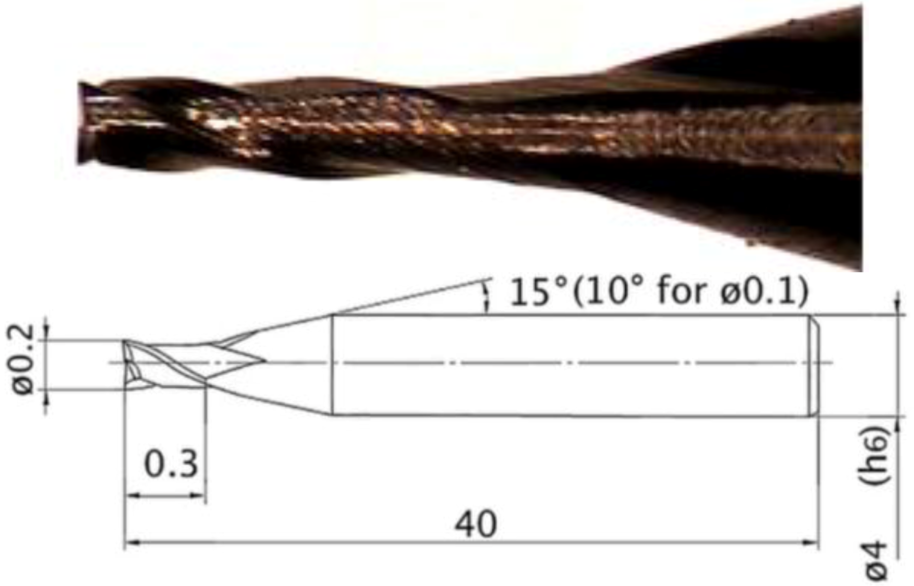
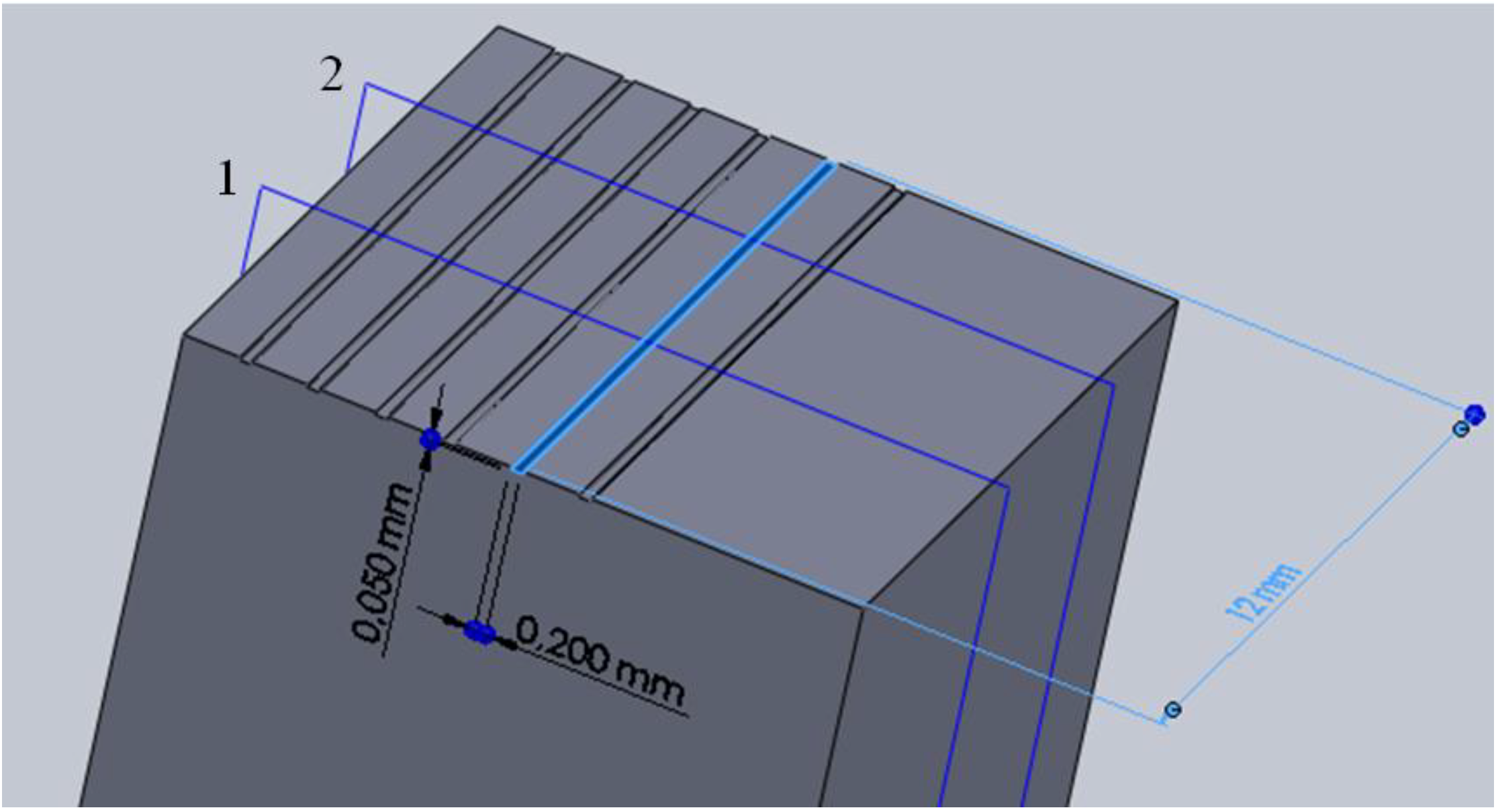
2.3. Micromilling Tests

3. Results and Discussions
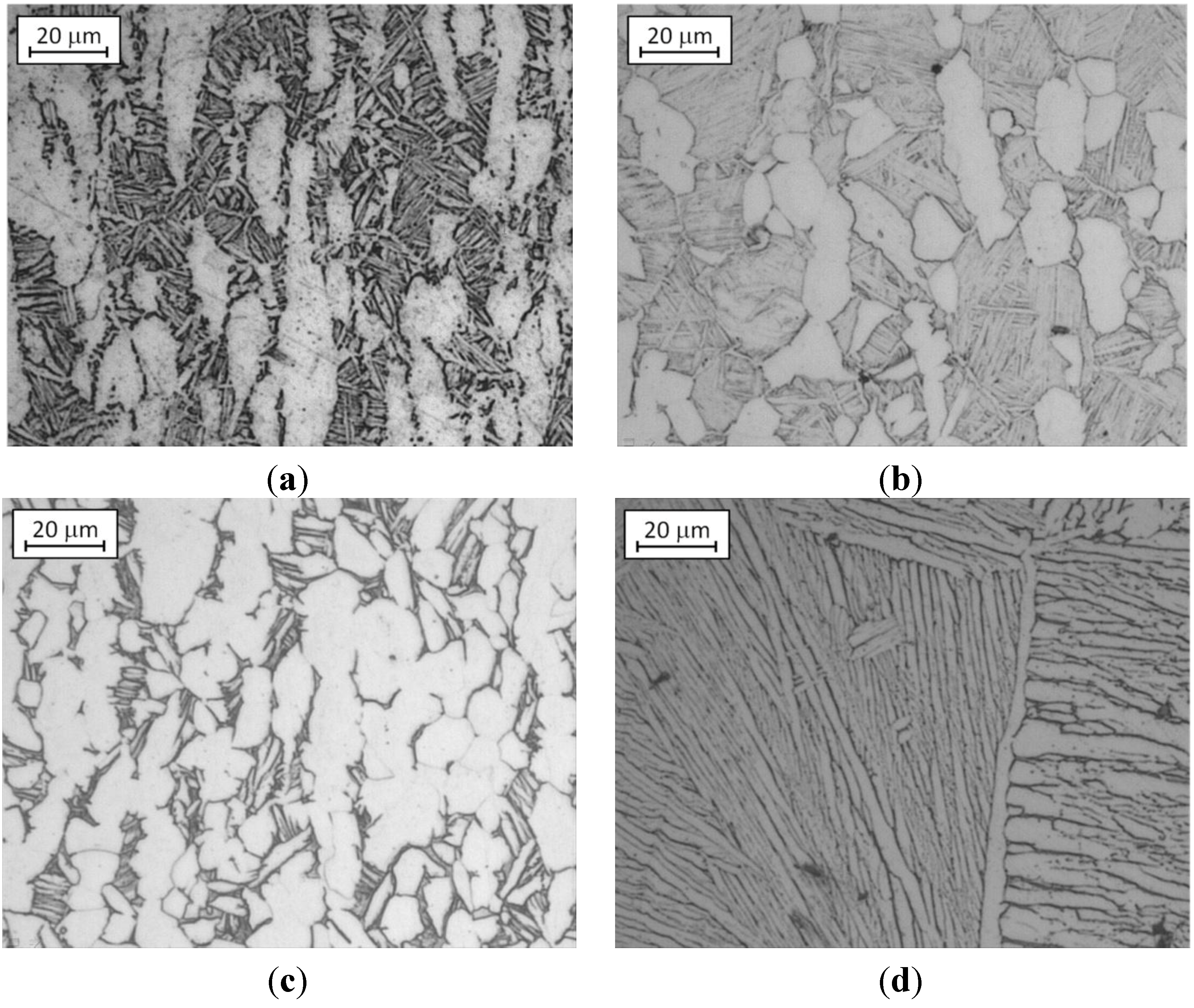
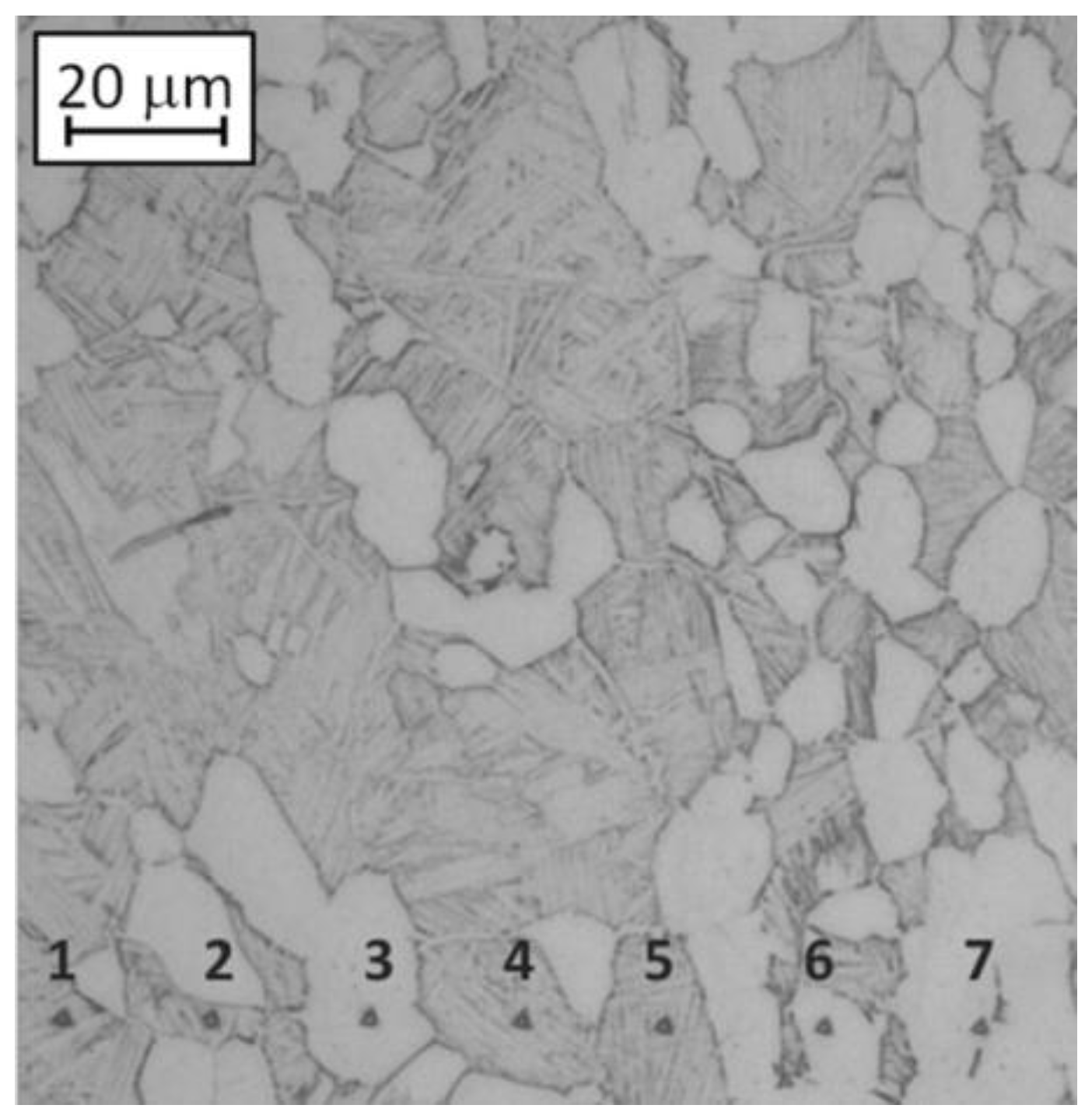
3.1. Microstructures Characterization

| microHV | Mill annealed | Bimodal | Fully equiaxed | Fully lamellar |
|---|---|---|---|---|
| Avg. | 386 | 411 | 397 | 356 |
| Std.dev. | 18 | 15 | 24 | 45 |
| Grain type | Mill annealed | Bimodal | Fully equiaxed | |||
|---|---|---|---|---|---|---|
| % | Hardness | % | Hardness | % | Hardness | |
| Equiaxed α grain | 43 | 499 ± 61 | 37 | 543 ± 46 | 87 | 481 ± 61 |
| Lamellar (α + β) grain | 57 | 397 ± 51 | 63 | 413 ± 30 | 13 | 417 ± 48 |
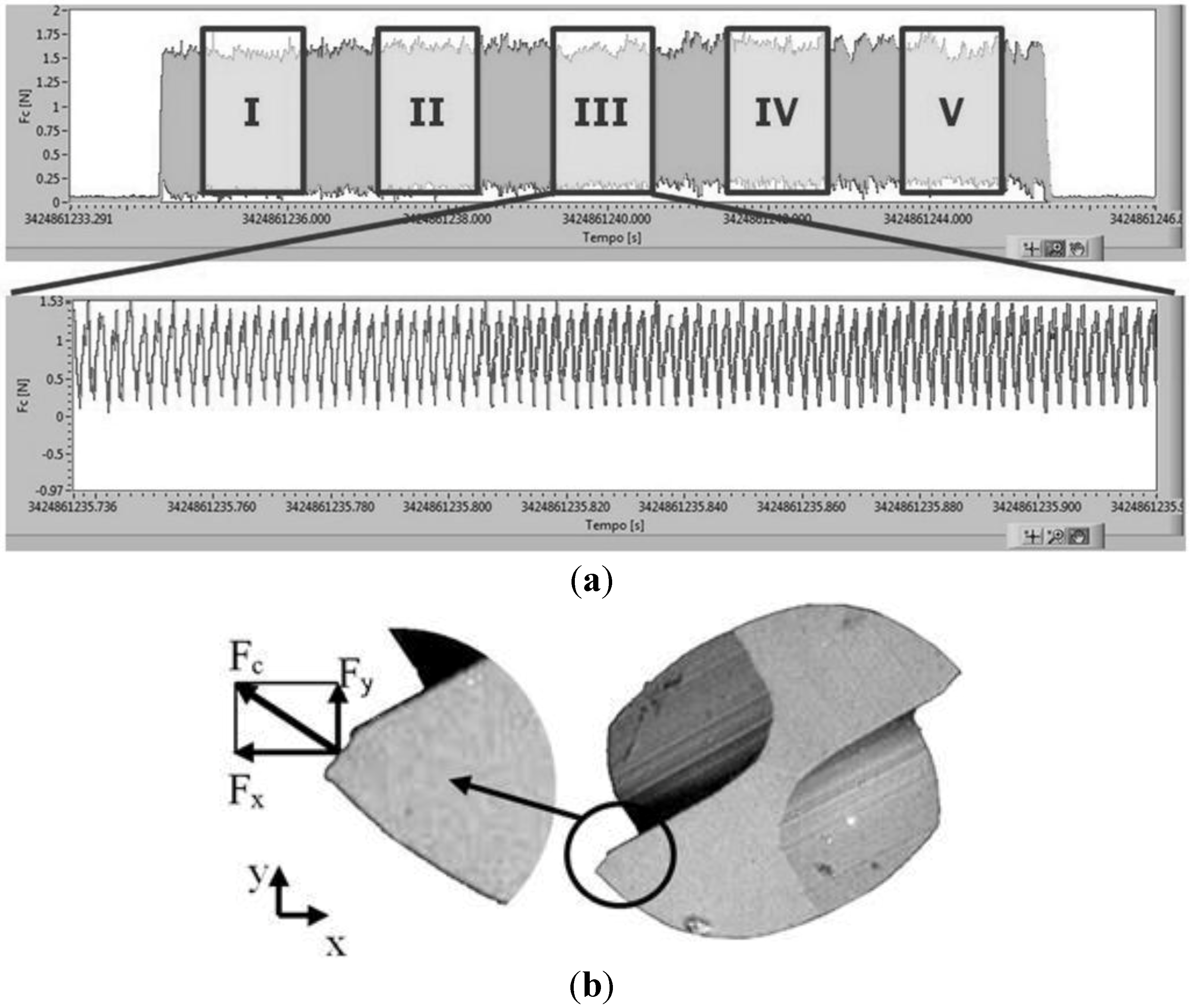
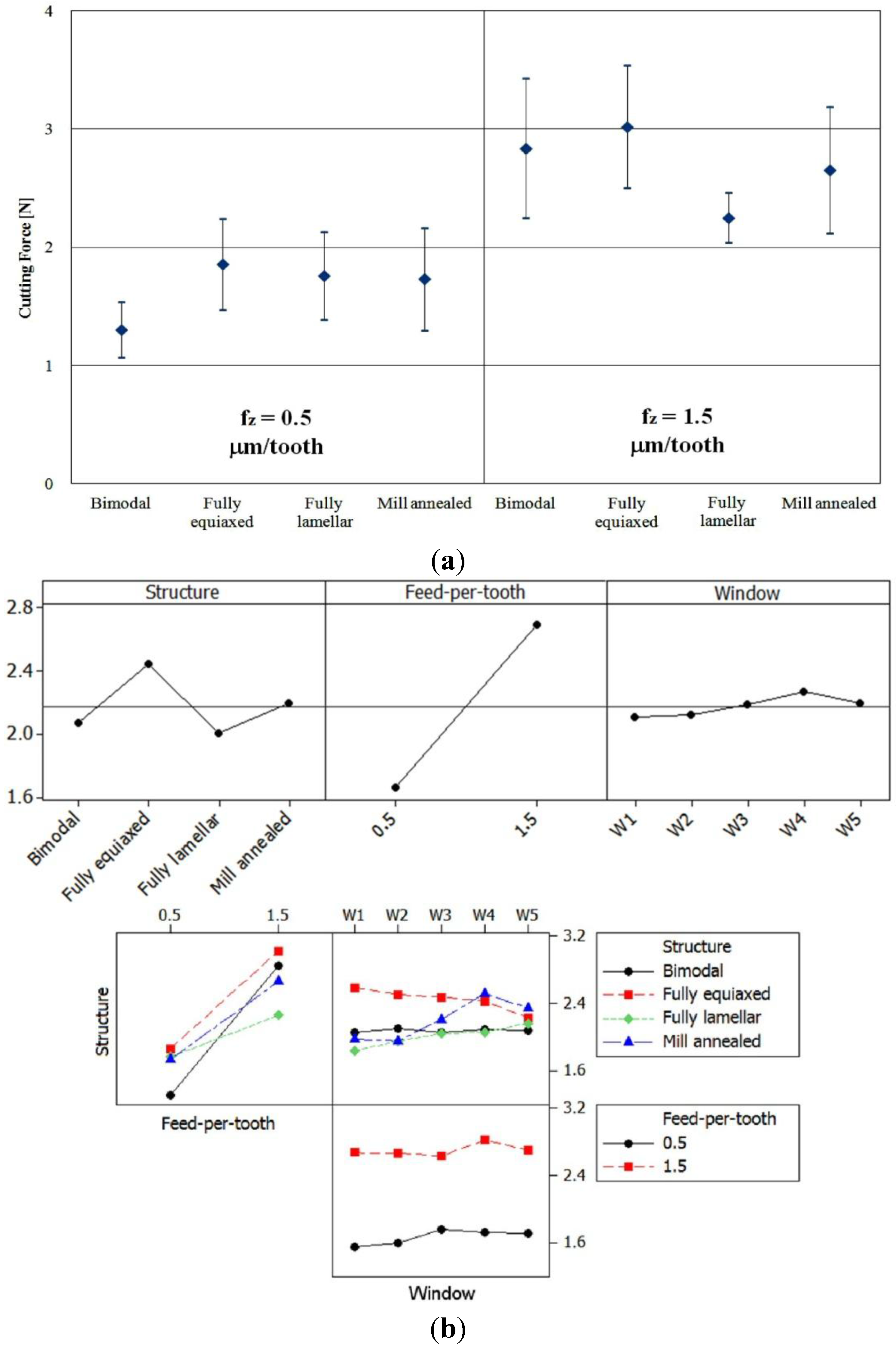
3.2. Cutting Forces


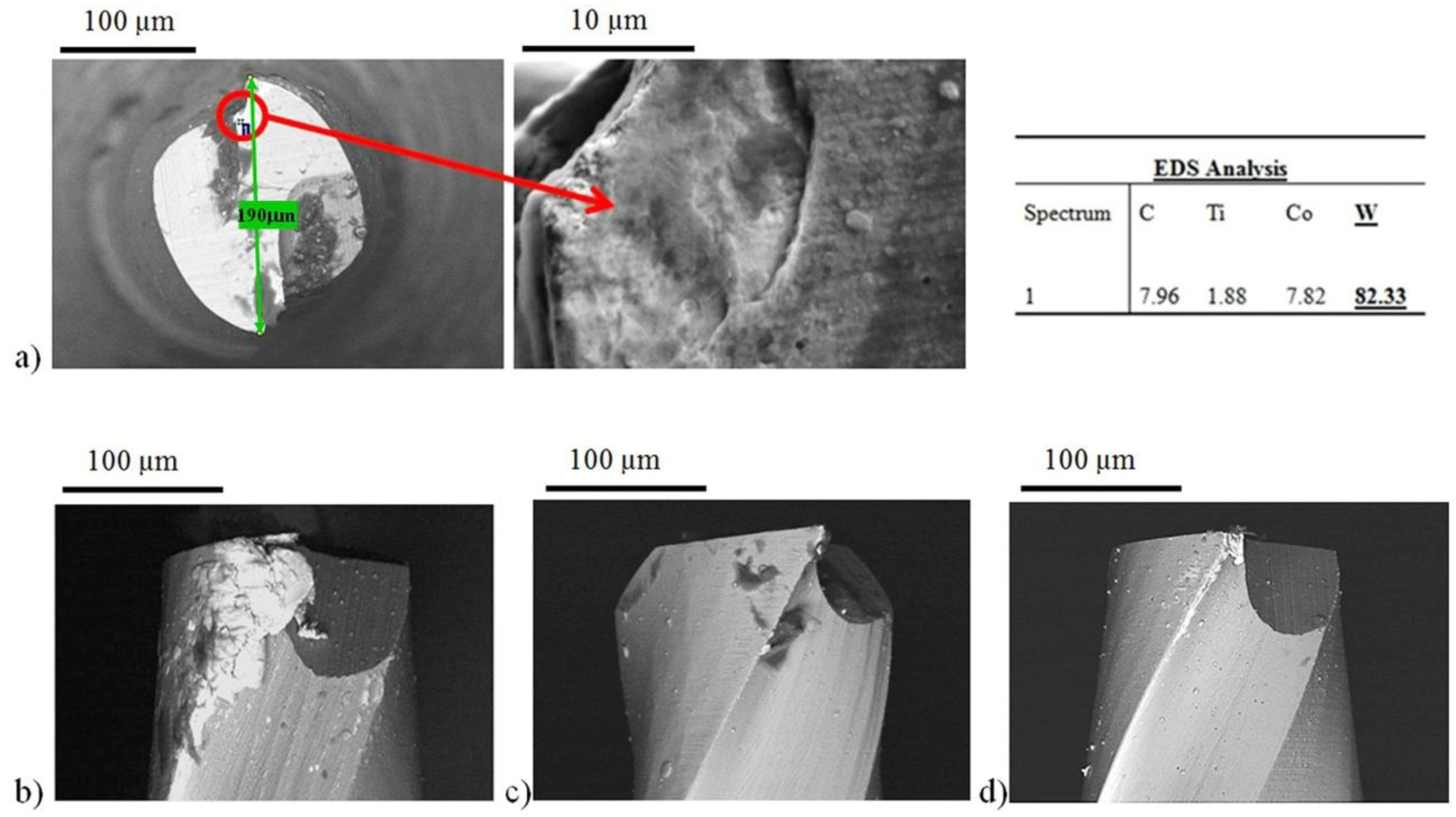
3.3. Tool Condition

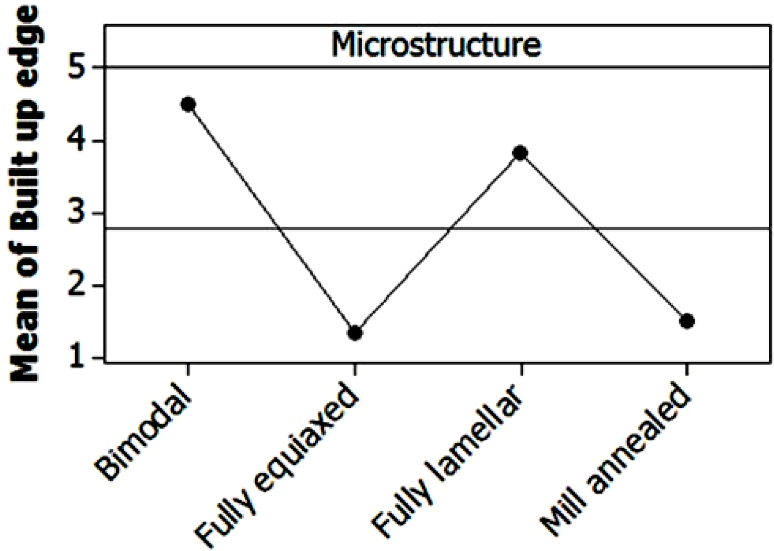
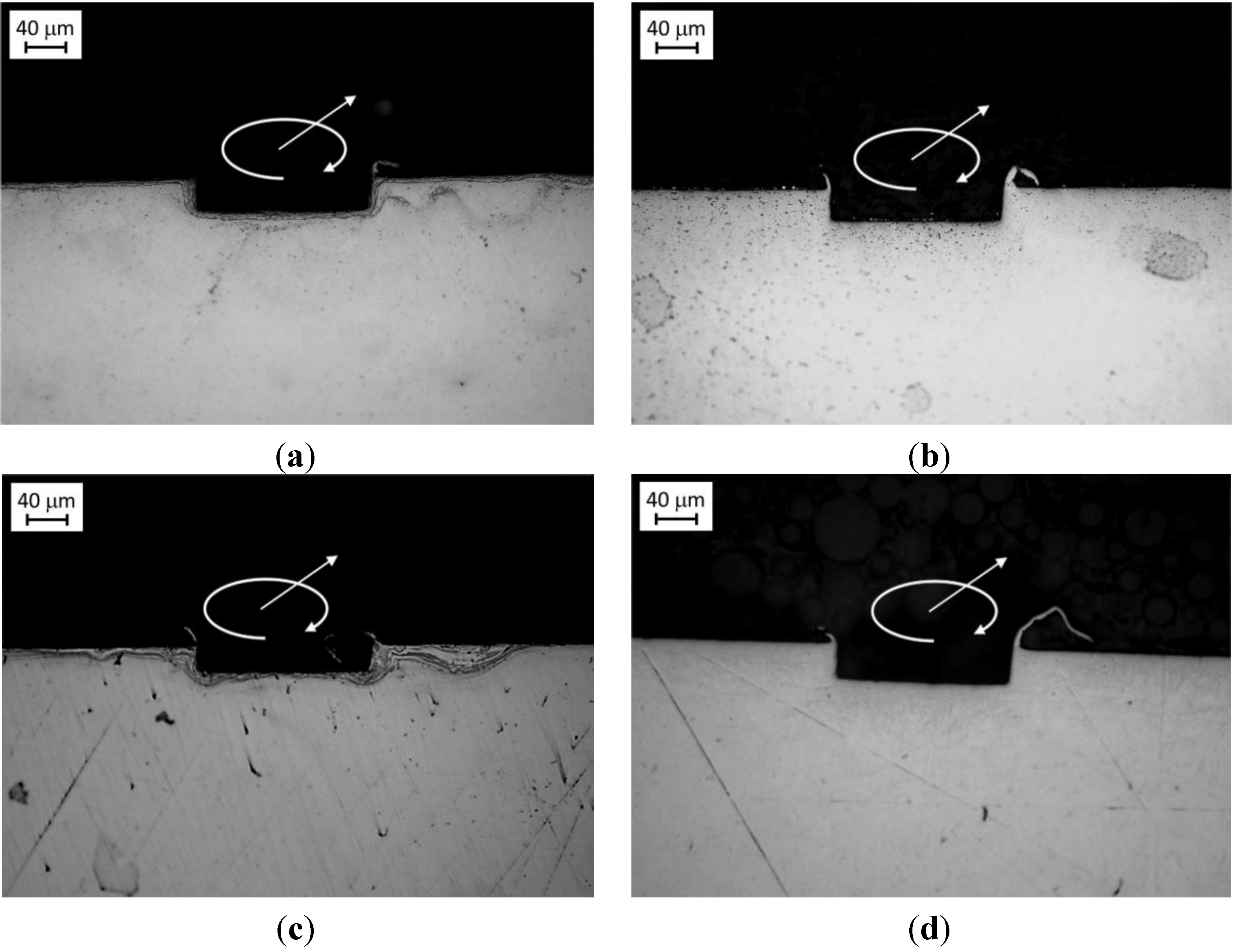
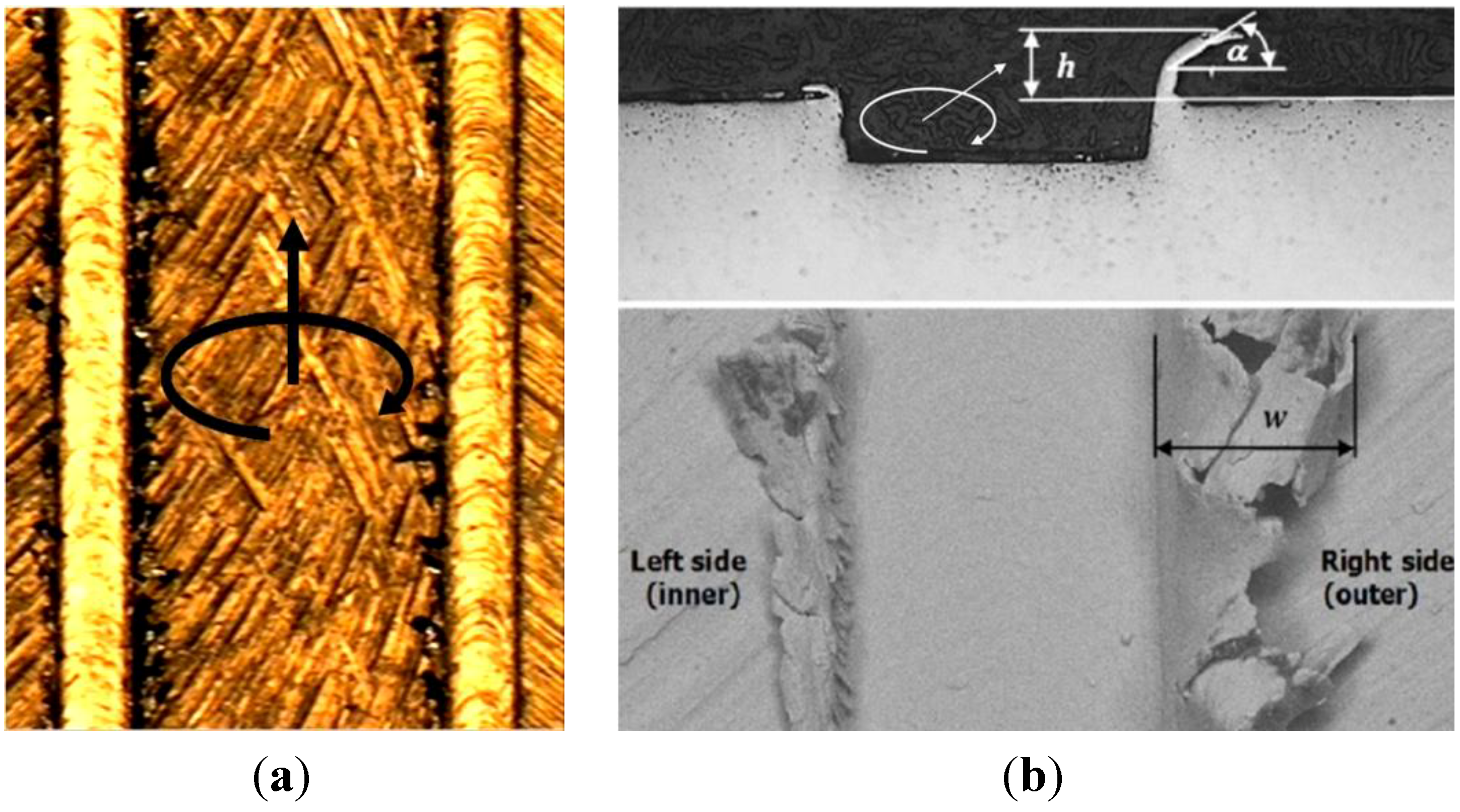
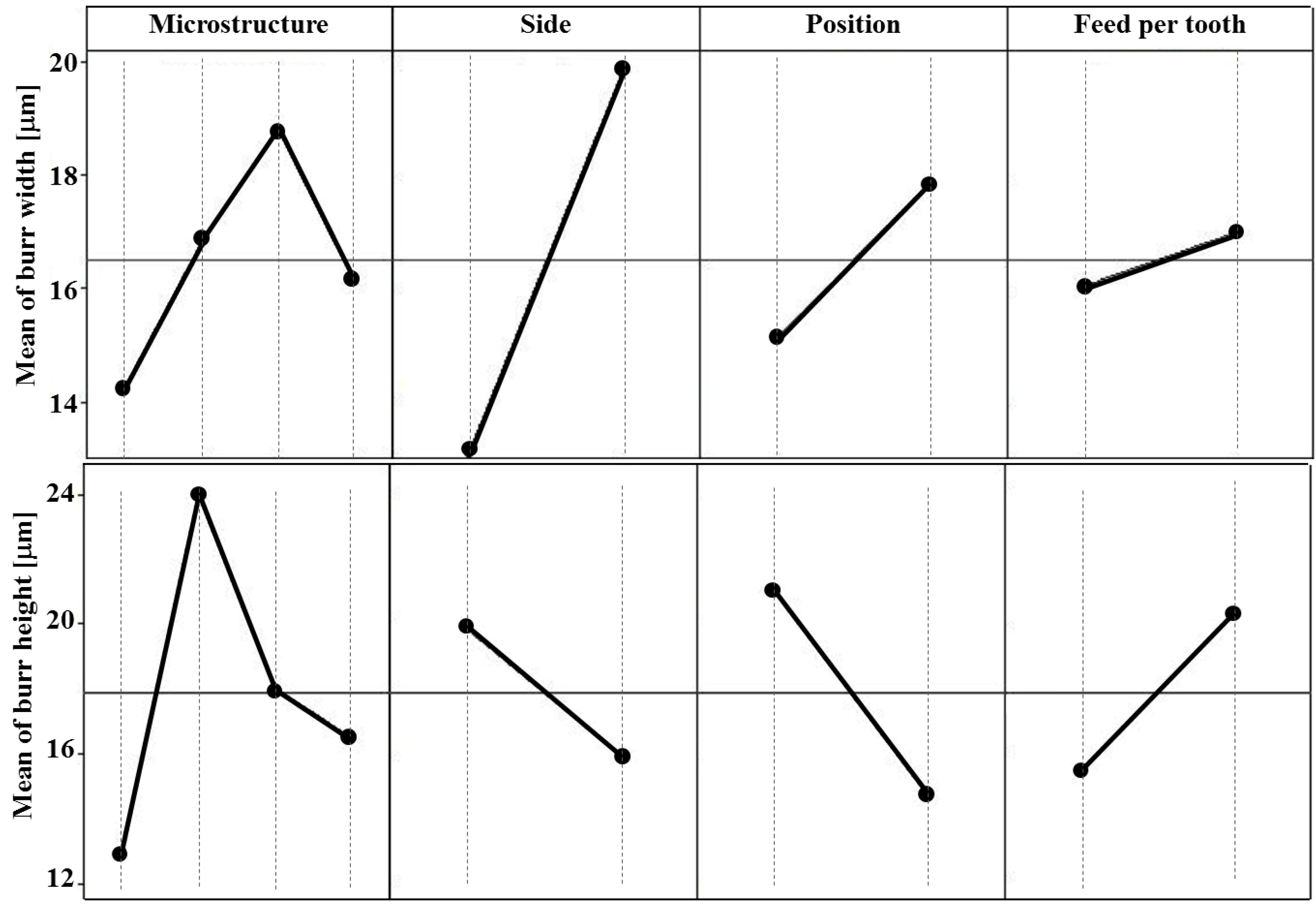
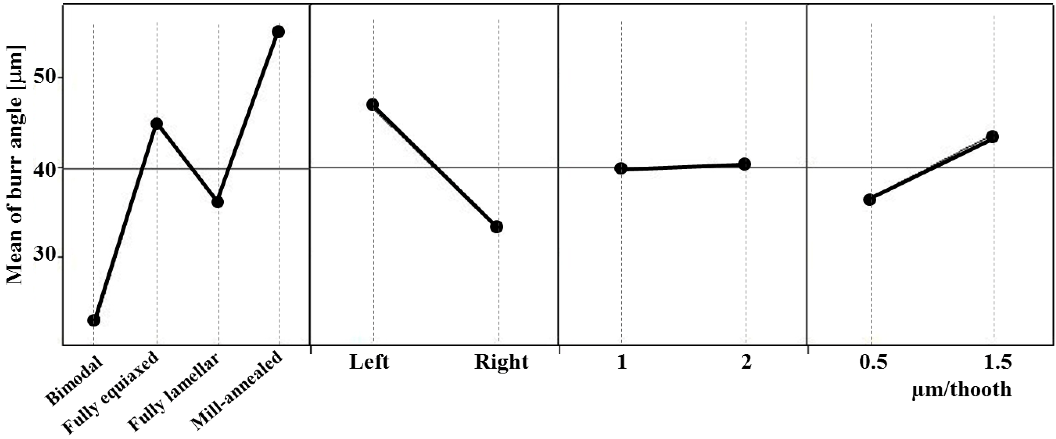
3.4. Channel Geometry and Burr Analysis


4. Conclusions
Acknowledgments
Conflicts of Interest
References
- Taniguchi, N. Current status in, and future trends of ultraprecision machining and ultrafine materials processing. CIRP Ann. Manuf. Technol. 1983, 32, 573–582. [Google Scholar] [CrossRef]
- Masuzawa, T. State of the art of micromachining. CIRP Ann. Manuf. Technol. 2000, 49, 473–488. [Google Scholar] [CrossRef]
- Alting, L.; Kimura, F.; Hansen, H.N.; Bissacco, G. Micro engineering. CIRP Ann. Manuf. Technol. 2003, 52, 635–657. [Google Scholar] [CrossRef]
- Meijer, J.; Du, K.; Gillner, A.; Hoffmann, D.; Kovalenko, V.S.; Masuzawa, T.; Ostendorf, A.; Poprawe, R.; Schulz, W. Laser machining by short and ultrashort pulses, state of the art and new opportunities in the age of the photons. CIRP Ann. Manuf. Technol. 2002, 51, 531–550. [Google Scholar] [CrossRef]
- Fleischer, J.; Buchholz, C.; Weule, H. Automation of the powder-injection-moulding process for micro-mechanical parts. CIRP Ann. Manuf. Technol. 2003, 52, 419–422. [Google Scholar] [CrossRef]
- Kim, S.G.; Traina, Z.; Lee, H.W. Folding assembly of micro-actuators. CIRP Ann. Manuf. Technol. 2008, 57, 29–32. [Google Scholar] [CrossRef]
- Okasha, M.M.; Mativenga, P.T.; Driver, N.; Li, L. Sequential laser and mechanical micro-drilling of Ni superalloy for aerospace application. CIRP Ann. Manuf. Technol. 2010, 59, 199–202. [Google Scholar] [CrossRef]
- Bartolo, P.; Kruth, J.-P.; Silva, J.; Levy, G.; Malshe, A.; Rajurkar, K.; Mitsuishi, M.; Ciurana, J.; Leu, M. Biomedical production of implants by additive electro-chemical and physical processes. CIRP Ann. Manuf. Technol. 2012, 61, 635–655. [Google Scholar] [CrossRef]
- Dornfeld, D.; Min, S.; Takeuchi, Y. Recent advances in mechanical micromachining. CIRP Ann. Manuf. Technol. 2006, 55, 745–768. [Google Scholar] [CrossRef]
- Bissacco, G.; Hansen, H.N.; de Chiffre, L. Size effects on surface generation in micro milling of hardened tool steel. CIRP Ann. Manuf. Technol. 2006, 55, 593–596. [Google Scholar] [CrossRef]
- Altintas, Y.; Jin, X. Mechanics of micro-milling with round edge tools. CIRP Ann. Manuf. Technol. 2011, 60, 77–80. [Google Scholar] [CrossRef]
- Zaman, M.T.; Senthil Kumar, A.; Rahman, M.; Sreeram, S. A three-dimensional analytical cutting force model for micro end milling operation. Int. J. Mach. Tool Manuf. 2006, 46, 353–366. [Google Scholar] [CrossRef]
- Özel, T.; Thepsonthi, T.; Ulutan, D.; Kaftanoğlu, B. Experiments and finite element simulations on micro-milling of Ti–6Al–4V alloy with uncoated and cBN coated micro-tools. CIRP Ann. Manuf. Technol. 2011, 60, 85–88. [Google Scholar] [CrossRef]
- Afazov, S.M.; Ratchev, S.M.; Segal, J. Modelling and simulation of micro-milling cutting forces. J. Mater. Process. Technol. 2010, 210, 2154–2162. [Google Scholar] [CrossRef]
- Jin, X.; Altintas, Y. Prediction of micro-milling forces with finite element method. J. Mater. Process. Techol. 2012, 212, 542–552. [Google Scholar] [CrossRef]
- Uhlmann, E.; Schauer, K. Dynamic load and strain analysis for the optimization of micro end mills. CIRP Ann. Manuf. Technol. 2005, 54, 75–78. [Google Scholar] [CrossRef]
- Aramcharoen, A.; Mativenga, P.T.; Yang, S.; Cooke, K.E.; Teer, D.G. Evaluation and selection of hard coatings for micro milling of hardened tool steel. Int. J. Mach. Tool Manufact. 2008, 48, 1578–1584. [Google Scholar] [CrossRef]
- Giorleo, L.; Ceretti, E.; Giardini, C. ALD coated tools in micro drilling of Ti sheet. CIRP Ann. Manuf. Technol. 2011, 60, 595–598. [Google Scholar] [CrossRef]
- Li, K.-M.; Chou, S.-Y. Experimental evaluation of minimum quantity lubrication in near micro-milling. J. Mater. Process. Technol. 2010, 210, 2163–2170. [Google Scholar] [CrossRef]
- Uhlmann, E.; Piltz, S.; Schauer, K. Micro milling of sintered tungsten—copper composite materials. J. Mater. Process. Technol. 2005, 167, 402–407. [Google Scholar] [CrossRef]
- Lekkala, R.; Bajpai, V.; Singh, R.K.; Joshi, S.S. Characterization and modeling of burr formation in micro-end milling. Precis. Eng. 2011, 35, 625–637. [Google Scholar] [CrossRef]
- Lampman, S. Wrought Titanium and Titanium Alloys. In Properties and Selection: Nonferrous Alloys and Special-Purpose Materials, 10th ed.; ASM International: Russell Township, OH, USA, 1990; Volume 2. [Google Scholar]
- Lütjering, G.; Williams, J.C. Titanium—Engineering Materials and Processes, 2nd ed.; Springer: Berlin, Germany, 2007. [Google Scholar]
- Matthew, J.D. Titanium: A Technical Guide; ASM International: Russell Township, OH, USA, 2000; p. 67. [Google Scholar]
- Monroy-Vázquez, K.P.; Attanasio, A.; Ceretti, E.; Siller, H.R.; Hendrichs-Troeglen, N.J.; Giardini, C. Evaluation of superficial and dimensional quality features in metallic micro-channels manufactured by micro-end-milling. Materials 2013, 6, 1434–1451. [Google Scholar] [CrossRef] [Green Version]
- Iost, A.; Bigot, R. Indentation size effect: Reality or artifact. J. Mater. Sci. 1996, 31, 3573–3577. [Google Scholar]
- Torster, F. Berichte aus der Werkstofftechnik, Shaker Verlag; TU Hamburg-Harburg: Aachen, Germany, 1995. [Google Scholar]
- Yun, H.T.; Heo, S.; Lee, M.K.; Min, B.-K.; Lee, S.J. Ploughing detection in micromilling processes using the cutting force signal. Int. J. Mach. Tools Manuf. 2011, 51, 377–382. [Google Scholar] [CrossRef]
- Lütjering, G.; Albrecht, J.; Ivasishin, O.M. Titanium '95, Science and Technology. In Proceedings of the Eighth World Conference on Titanium, Birmingham, UK, 22–26 October 1995; The University Press: Cambridge, UK, 1996; p. 1163. [Google Scholar]
© 2013 by the authors; licensee MDPI, Basel, Switzerland. This article is an open access article distributed under the terms and conditions of the Creative Commons Attribution license (http://creativecommons.org/licenses/by/3.0/).
Share and Cite
Attanasio, A.; Gelfi, M.; Pola, A.; Ceretti, E.; Giardini, C. Influence of Material Microstructures in Micromilling of Ti6Al4V Alloy. Materials 2013, 6, 4268-4283. https://doi.org/10.3390/ma6094268
Attanasio A, Gelfi M, Pola A, Ceretti E, Giardini C. Influence of Material Microstructures in Micromilling of Ti6Al4V Alloy. Materials. 2013; 6(9):4268-4283. https://doi.org/10.3390/ma6094268
Chicago/Turabian StyleAttanasio, Aldo, Marcello Gelfi, Annalisa Pola, Elisabetta Ceretti, and Claudio Giardini. 2013. "Influence of Material Microstructures in Micromilling of Ti6Al4V Alloy" Materials 6, no. 9: 4268-4283. https://doi.org/10.3390/ma6094268