Nitrogen Doped Carbon Nanotubes from Organometallic Compounds: A Review


Abstract
:1. Overview

2. Nitrogen Doped CNTs (N-CNTs)
2.1. Properties of N-CNTs
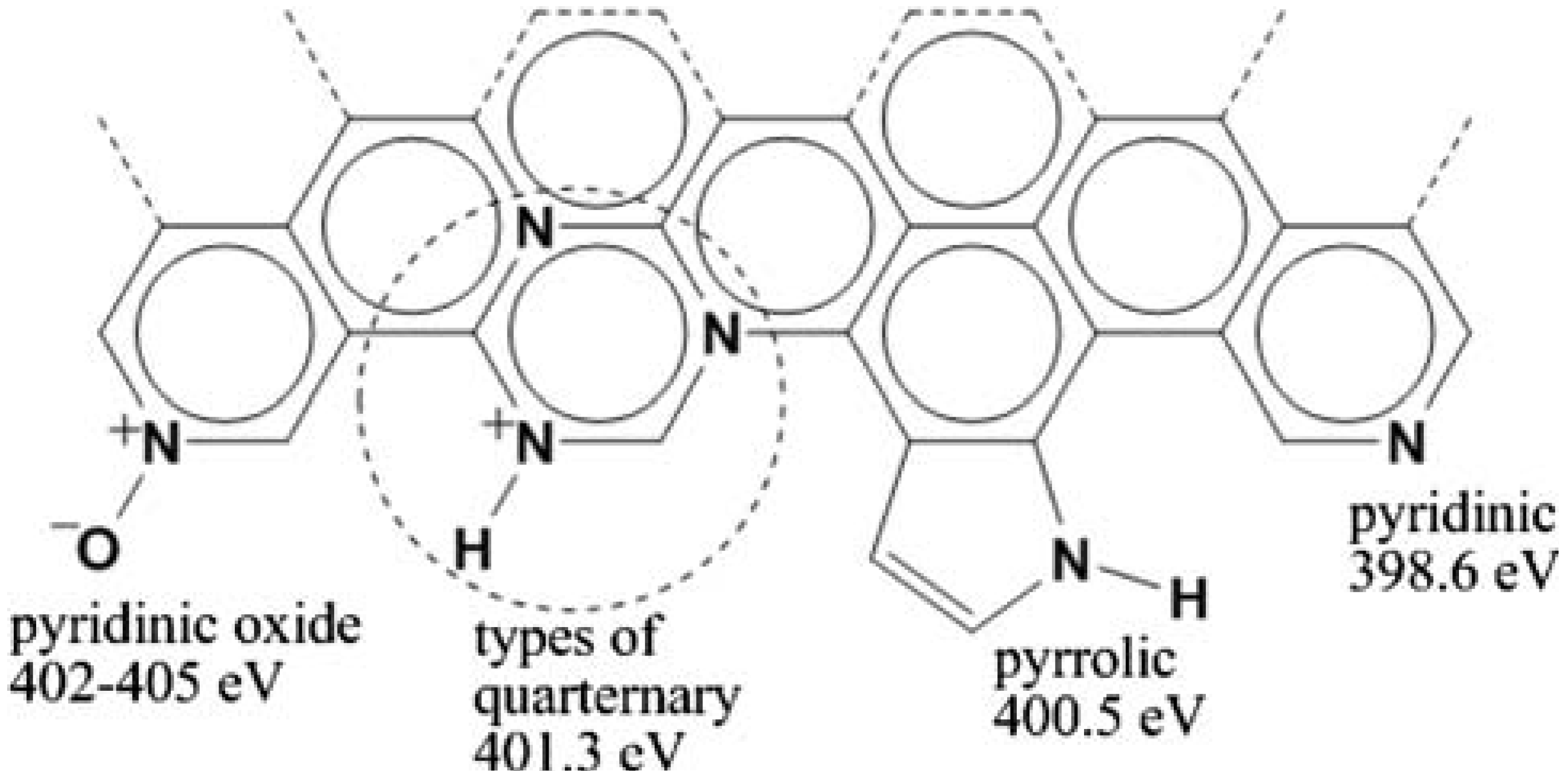
2.1.1. N bonding in CNTs

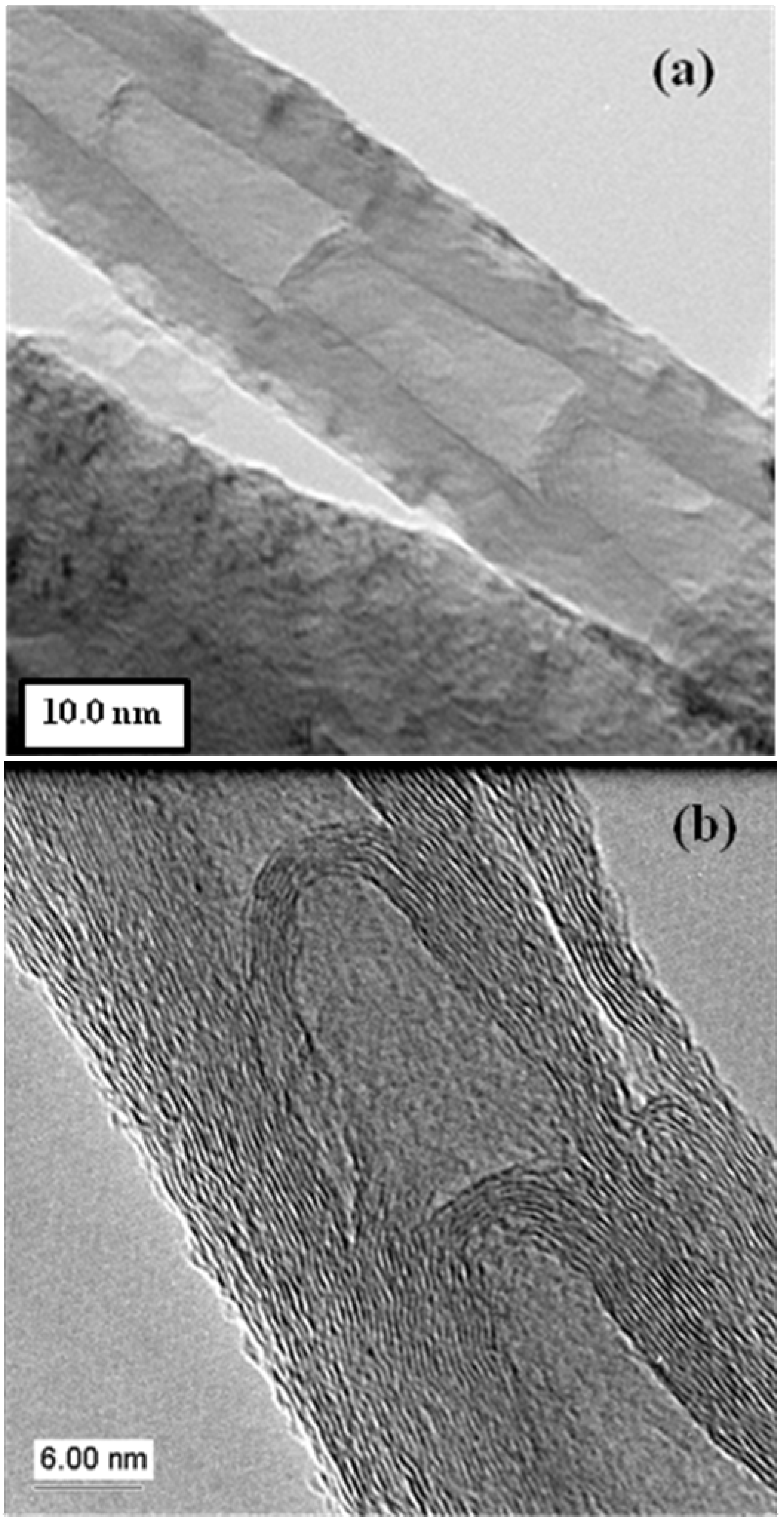
2.1.2. N-CNT bamboo structures

2.1.3. Chemical properties of N-CNTs
2.1.4. Physical properties of N-CNTs
2.2. Characterization techniques
2.3. Applications of N-CNTs
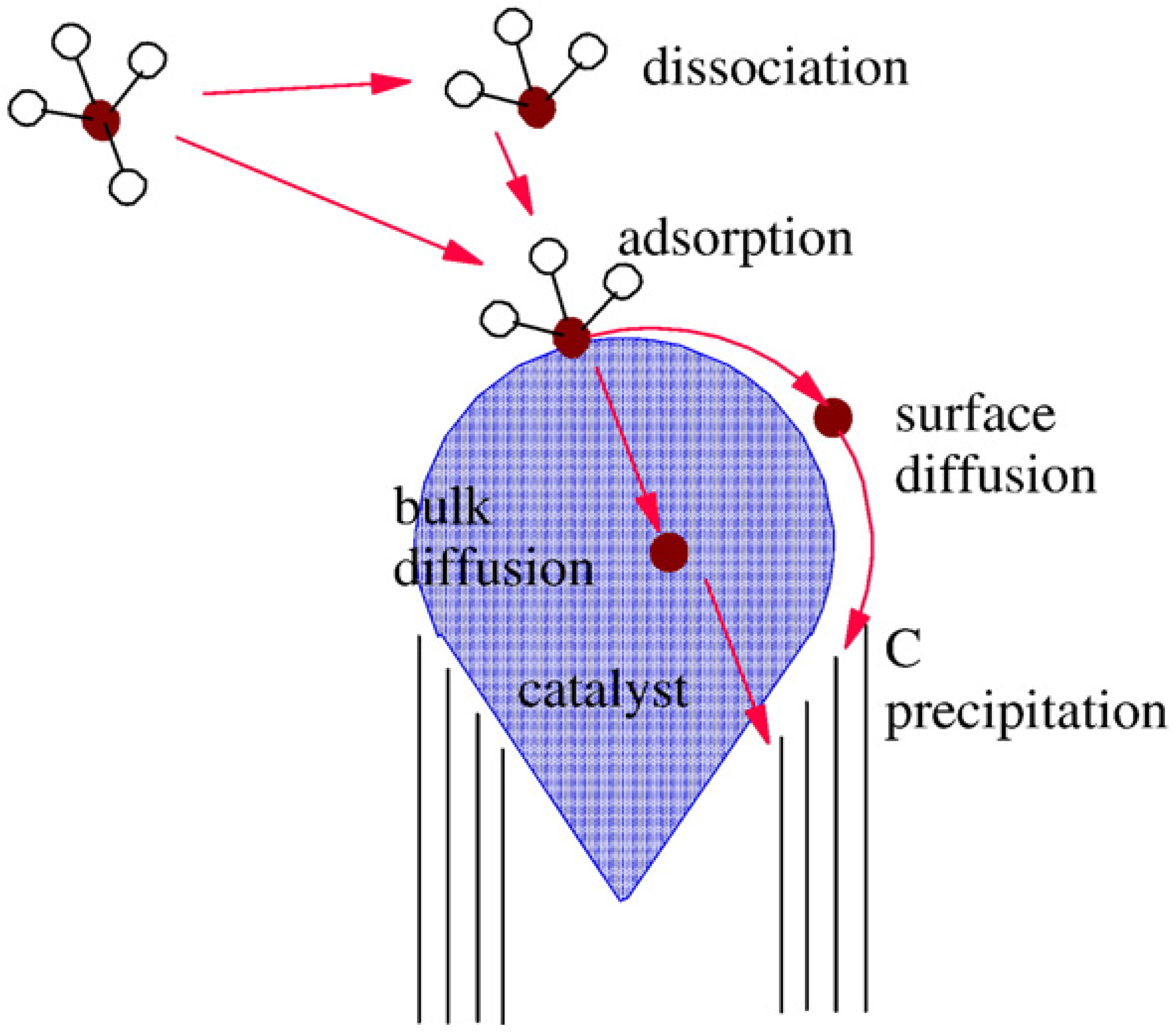
2.4. N-CNT synthesis mechanism

3. N-CNT Synthesis from Organometallic Complexes

| N/C sources | Substrate | Catalyst | T (°C) | N (at %) | Method | Ref |
|---|---|---|---|---|---|---|
| Ethanol/toluene/ethylenediamine | - | FcH | 850–950 | - | CVD injection | 14 |
| Toluene/aniline, ferrocenylaniline | - | FcH, ferrocenyl-aniline | 900 | 1.5 | FC CVD | 15 |
| Triphenylphosphine/benzylamine | - | FcH | 720–840 | - | CVD aerosol | 18 |
| Toluene/hexamethylenediamine, benzylamine, quinoline | - | FcH | 850 | CVD aerosol | 26 | |
| Pyridine | Quartz tube | Fe(CO)5 | 900–1100 | - | CVD | 32 |
| Benzene/CH3CN | Quartz tube | FcH, AgNO3 | 900 | - | CVD aerosol | 35 |
| Ethanol/benzylamine | - | FcH | 950 | < 2 | CVD | 42 |
| Benzylamine | - | FcH | 850 | - | CVD | 50 |
| Xylene/NH3/pyridine | - | FcH | 800 | 0–9.7 | FC CVD | 60 |
| Thiophene/NiPc | - | Nickelocene, NiPc | 900 | - | CVD | 64 |
| Fullerene/NH3 | - | FcH | 1050 | > 0.1 | CVD | 73 |
| Ethylenediamine | - | Co, FcH | 780–1080 | 18.77–24.45 | CVD injection | 82 |
| 4-tert-butylpyridine | Quartz | FcH | 700 | 1.6–2 | CVD aerosol | 85 |
| Toluene/benzylamine | Quartz substrate | FcH | 800–900 | 0 – 2.2 | CVD aerosol | 88 |
| CH3CN/THF | Carbon fiber paper | Fe acetylacetonate | 850 | 0 – 2.2 | CVD aerosol assisted | 99 |
| C2H2/NH3 | - | Fe(CO)5 | 750–950 | 3.1–7.2 | CVD | 139 |
| Monoethanolamine | Si | FcH | 900 | 6.6 | CVD | 146 |
| Monoethanolamine | GaAs | FcH | 950 | 7.8 | CVD | 146 |
| C3H6N6 | - | FcH | 900–1000 | 2.3–11.5 | FC CVD | 147 |
| Ethanol/ethylenediamine | Al2O3 | FcH | 900 | 1.2 | CVD injection | 148 |
| NH3/pyridine | Quartz tube | FcH | 700–1000 | 4.8–8.8 | CVD | 149 |
| FePc/thiophene/NH3 | - | FePc | 900 | < 9.0 | CVD | 156 |
| CoPc/thiophene | - | CoPc | 800–1000 | 1.9–2.9 | CVD | 158 |
| CH3CN/pyridine | - | FcH | 650–900 | - | FC CVD | 165 |
| Pyridine, methylpyrimidine, triazine | - | Fe(CO)5 | 1100 | 2.3 | CVD | 166 |
| Melamine | FcH | 1050 | 2.0–7.0 | 167 | ||
| C18H15P | Quartz tube | FcH | 950 | - | CVD | 168 |
| Pyridine, pyrimidine | - | FcH | 750 | 1.0 – 3.2 | CVD | 169 |
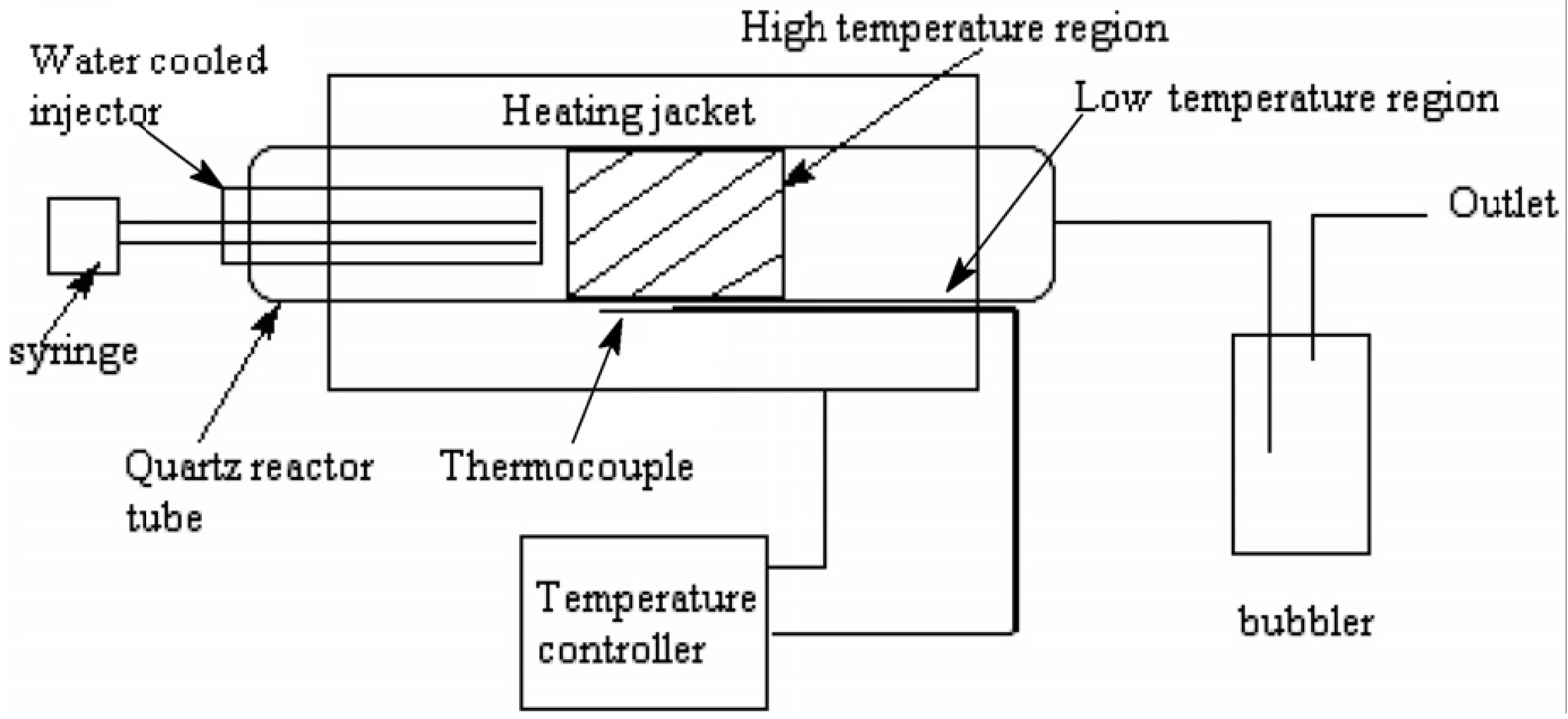
3.1. Flow system
3.2. Closed system
3.3. Non-flow systems
3.4. Alternative synthetic strategies
4. Other N Doped Shaped Carbon Nanomaterials
5. Conclusions
Acknowledgements
References
- Iijima, S. Helical microtubules of graphitic carbon. Nature 1991, 354, 56–58. [Google Scholar] [CrossRef]
- Bethune, D.; Kiang, C-H.; de Vries, M.; Gorman, G.; Savoy, R.; Vazquez, J.; Beyers, R. Cobalt-catalyzed growth of carbon nanotubes with single-atomic-layer walls. Nature 1993, 363, 605–607. [Google Scholar] [CrossRef]
- Nikolaev, P.; Bronikowski, J.; Bradley, R.K.; Rohmund, F.; Colbert, D.T.; Smith, K.A.; Smalley, R.E. Gas-phase catalytic growth of single-walled carbon nanotubes from carbon monoxide. Chem. Phys. Lett. 1999, 313, 91–97. [Google Scholar] [CrossRef]
- Nerushev, O.A.; Sveningsson, M.; Falk, L.K.L.; Rohmund, F.J. Carbon nanotube films obtained by thermal chemical vapour deposition. J. Mat. Chem. 2001, 11, 1122–1132. [Google Scholar] [CrossRef]
- Amelinckx, S.; Zhang, X.B.; Bernaerts, D.; Zhang, X.F.; Ivanov, V.; Nagy, J.B. A formation mechanism for catalytically grown helix-shaped graphite nanotubes. Science 1994, 265, 635–639. [Google Scholar] [CrossRef] [PubMed]
- Dupuis, A.C. The catalyst in the CCVD of carbon nanotubes—A review. Prog. Mater. Sci. 2005, 50, 929–961. [Google Scholar] [CrossRef]
- Park, J.B.; Choi, G.S.; Cho, Y.S.; Hong, S.Y.; Kim, D.; Choi, S.Y.; Lee, J.H.; Cho, K.I. Characterization of Fe-catalyzed carbon nanotubes grown by thermal chemical vapor deposition. Cryst. Growth 2002, 244, 211–217. [Google Scholar] [CrossRef]
- Mohlala, M.S.; Liu, X.Y.; Robinson, J.M.; Coville, N.J. Organometallic precursors for use as catalysts in carbon nanotube synthesis. Organometallics 2005, 24, 972–976. [Google Scholar] [CrossRef]
- Cassell, A.M.; Raymakers, J.A.; Kong, J.; Dai, H. Large scale CVD synthesis of single-walled carbon nanotubes. J. Phys. Chem. B 1999, 103, 6484–6492. [Google Scholar] [CrossRef]
- Li, Q.W.; Yan, H.; Cheng, Y.; Zhang, J.; Liu, Z.F. A scalable CVD synthesis of high-purity single-walled carbon nanotubes with porous MgO as support material. J. Mater. Chem. 2002, 12, 1179–1183. [Google Scholar] [CrossRef]
- Colomer, J.F.; Stephan, C.; Lefrant, S.; Van Tendeloo, G.; Willems, I.; Konya, Z.; Laurent, Ch.; Nagy, J.B. Large-scale synthesis of single-wall carbon nanotubes by catalytic chemical vapor deposition (CCVD) method. Chem. Phys. Lett. 2000, 317, 83–89. [Google Scholar] [CrossRef] [Green Version]
- Maiyalagan, T.; Viswanathan, B. Template synthesis and characterization of well-aligned nitrogen containing carbon nanotubes. Mater. Chem. Phys. 2005, 93, 291–295. [Google Scholar] [CrossRef]
- Stephen, O.; Ajayan, P.M.; Colliex, C.; Redlich, Ph.; Lambert, J.M.; Bernier, P.; Letin, P. Doping graphitic and carbon nanotube structures with boron and nitrogen. Science 1994, 266, 1683–1685. [Google Scholar] [CrossRef] [PubMed]
- Feng, J.; Li, Y.; Hou, F.; Zhong, X. Controlled growth of high quality bamboo carbon nanotube arrays by the double injection chemical vapor deposition process. Mater. Sci. Eng. A 2008, 473, 238–243. [Google Scholar] [CrossRef]
- Nxumalo, E.N.; Nyamori, V.O.; Coville, N.J. CVD synthesis of nitrogen doped carbon nanotubes using ferrocene/aniline mixtures. J. Organomet. Chem. 2008, 693, 2942–2948. [Google Scholar] [CrossRef]
- Tao, X.Y.; Zhang, X.B.; Sun, F.Y.; Cheng, J.P.; Liu, F.; Luo, Z.Q. Large-scale CVD synthesis of nitrogen-doped multi-walled carbon nanotubes with controllable nitrogen content on a CoxMg1−xMoO4 catalyst. Diamond Relat. Mater. 2007, 16, 425–430. [Google Scholar] [CrossRef]
- Lin, F.; Hsu, C.; Tang, T.; Kang, P.; Yang, F. Thermal-heating CVD synthesis of BN nanotubes from trimethyl borate and nitrogen gas. Mater. Chem. Phys. 2008, 107, 115–121. [Google Scholar] [CrossRef]
- Cruz-Silva, E.; Cullen, D.A.; Gu, L.; Romo-Herrera, J.M.; Muñoz-Sandoval, E.; López-Urías, F.; Sumpter, B.G.; Meunier, V.; Charlier, J.-C.; Smith, D.J.; Terrones, H.; Terrones, M. Heterodoped nanotubes: Theory, synthesis, and characterization of phosphorus-nitrogen doped multiwalled carbon nanotubes. ACS Nano 2008, 2, 441–448. [Google Scholar] [CrossRef] [PubMed]
- Mondal, K.; Coville, N.J.; Witcomb, M.J.; Havel, J.; Tejral, G. Boron mediated synthesis of multiwalled carbon nanotubes by chemical vapor deposition. Chem. Phys. Lett. 2007, 43, 787–791. [Google Scholar]
- Ewels, C.P.; Glerup, M. Nitrogen doping in carbon nanotubes. J. Nanosci. Nanotechnol. 2005, 5, 1345–1363. [Google Scholar] [CrossRef] [PubMed]
- Van Dommele, S.; Van de Jong, K.P.; Bitter, J.H. Nitrogen-containing carbon nanotubes as solid base catalysts. Chem. Commun. 2006, 4859–4861. [Google Scholar] [CrossRef]
- Van Dommele, S.; Romero-Izquirdo, A.; Brydson, R.; de Jong, K.P.; Bittera, J.H. Tuning nitrogen functionalities in catalytically grown nitrogen-containing carbon nanotubes. Carbon 2008, 46, 138–148. [Google Scholar] [CrossRef]
- Ayala, P.; Arenal, R.; Rummeli, M.; Rubio, A.; Pichler, T. The doping of carbon nanotubes with nitrogen and their potential applications. Carbon 2010, 48, 575–586. [Google Scholar] [CrossRef]
- Robertson, J.; Davis, C.A. Nitrogen doping of tetrahedral amorphous carbon. Diamond Relat. Mater. 1995, 4, 441–444. [Google Scholar] [CrossRef]
- Biddinger, E.J.; von Deak, D.; Ozkan, U.S. Nitrogen-containing carbon nanostructures as oxygen-reduction catalysts. Top. Catal. 2009, 52, 1566–1574. [Google Scholar] [CrossRef]
- Letsoala, P.J.; Cele, L.M.; Nxumalo, E.N.; Coville, N.J. The influence of nitrogen sources on nitrogen doped multi-walled carbon nanotubes. Unpublished work.
- Ghosh, P.; Zamri, M.; Subramanian, M.; Soga, T.; Jimbo, T.; Katoh, R.; Tanemura1, M. Bamboo-shaped aligned CNx nanotubes synthesized using single feedstock at different temperatures and study of their field electron emission. J. Phys. D: Appl. Phys. 2008, 41, 155405–155412. [Google Scholar] [CrossRef]
- Zhang, X.X.; Li, Z.Q.; Wen, G.H.; Fung, K.K.; Chen, J.; Li, Y. Microstructure and growth of bamboo-shaped carbon nanotubes. Chem. Phys. Lett. 2001, 333, 509–514. [Google Scholar] [CrossRef]
- Wang, Y.Y.; Tang, G.Y.; Koeck, F.A.M.; Brown, B.; Garguilo, J.M.; Nemanich, R.J. Experimental studies of the formation process and morphologies of carbon nanotubes with bamboo mode structures. Diamond Relat. Mater. 2004, 13, 1287–1291. [Google Scholar] [CrossRef]
- Kudashov, A.G.; Okotrub, A.V.; Bulusheva, L.G.; Asanov, I.P.; Shubin, Yu.V.; Yudanov, N.F.; Yudanova, L.I.; Danilovich, V.S.; Abrosimov, O.G. Influence of Ni-Co catalyst composition on nitrogen content in carbon nanotubes. J. Phys. Chem. B 2004, 108, 9048–9053. [Google Scholar] [CrossRef]
- Lin, C.H.; Chang, H.L.; Hsu, C.M.; Lo, A.Y.; Kuo, C.T. The role of nitrogen in carbon nanotube formation. Diamond Relat. Mater. 2003, 12, 1851–1857. [Google Scholar] [CrossRef]
- Bajpai, V.; Dai, L.; Ohashi, T. Large-scale synthesis of perpendicularly aligned helical carbon nanotubes. J. Am. Chem. Soc. 2004, 126, 5070–5071. [Google Scholar] [CrossRef]
- Mamo, M.A.; Freitas, F.S.; de Freitas, J.N.; van Otterlo, W.A.L.; Nogueira, A.F.; Coville, N.J. Application of 3-hexylthiophene functionalized CNTs in photovoltaic devices. Unpublished work.
- Jang, J.W.; Lee, C.E.; Lyu, S.C.; Lee, T.J.; Lee, C.J. Structural study of nitrogen-doping effects in bamboo-shaped multiwalled carbon nanotubes. Appl. Phys. Lett. 2004, 84, 2877–2879. [Google Scholar] [CrossRef]
- Yadav, R.M.; Dobal, P.S.; Shripathi, T.; Katiyar, R.S.; Srivastava, O.N. Effect of growth temperature on bamboo-shaped carbon–nitrogen (C–N) nanotubes synthesized using ferrocene acetonitrile precursor. Nanoscale Res. Lett. 2009, 4, 197–203. [Google Scholar] [CrossRef]
- Yadav, R.M.; Singh, D.P.; Shripathi, T.; Srivastava, O.N. Synthesis of C–N nanotube blocks and Y-junctions in bamboo-like C–N nanotubes. J. Nanopart. Res. 2008, 10, 1349–1354. [Google Scholar] [CrossRef]
- Jiang, J.; Feng, T.; Cheng, X.; Dai, L.; Cao, G.; Jiang, B.; Wang, X.; Liu, X.; Zou, S. Synthesis and growth mechanism of Fe-catalyzed carbon nanotubes by plasma-enhanced chemical vapor deposition. Nucl. Instrum. Meth. B 2006, 244, 327–332. [Google Scholar] [CrossRef]
- Lee, C.J.; Park, J. Growth model of bamboo-shaped carbon nanotubes by thermal chemical vapor deposition. Appl. Phys. Lett. 2000, 77, 3397–3399. [Google Scholar] [CrossRef]
- Trasobares, S.; Stephan, O.; Colliex, C.; Hsu, W.K.; Kroto, H.W.; Walton, D.R.M. Compartmentalized CNx nanotubes: Chemistry, morphology, and growth. J. Chem. Phys. 2002, 116, 8966–8972. [Google Scholar] [CrossRef]
- Sinnot, S.B.; Andrews, R.; Qian, D.; Rao, A.M.; Mao, Z.; Dickey, E.C.; Derbyshire, F. Model of carbon nanotube growth through chemical vapor deposition. Chem. Phys. Lett. 1999, 315, 25–30. [Google Scholar] [CrossRef]
- Glerup, M.; Steinmetz, J.; Samaille, D.; Stephan, O.; Enouz, S.; Loiseau, A.; Roth, S.; Bernier, P. Synthesis of N-doped SWNT using the arc-discharge procedure. Chem. Phys. Lett. 2004, 387, 193–197. [Google Scholar] [CrossRef]
- Villalpando-Paez, F.; Zamudio, A.; Elias, A.L.; Son, H.; Barros, E.B.; Chou, S.G.; Kim, Y.A.; Muramatsu, H.; Hayashi, T.; Kong, J.; Terrones, H.; Dresselhaus, G.; Endo, M.; Terrones, M.; Dresselhaus, M.S. Synthesis and characterization of long strands of nitrogen-doped single-walled carbon nanotubes. Chem. Phys. Lett. 2006, 424, 345–352. [Google Scholar] [CrossRef]
- Lin, H.; Lagoute, J.; Chacon, J.; Arenal, R.; Stephan, O.; Repain, V.; Girard, Y.; Enouz, S.; Bresson, L.; Rousset, S.; Loiseau, A. Combined STM/STS, TEM/EELS investigation of CNx-SWNTs. Phys. Stat. Sol. B 2008, 245, 1986–1989. [Google Scholar] [CrossRef]
- Lin, H.; Arenal, R.; Enouz-Vedrenne, S.; Stephan, O.; Loiseau, A. Nitrogen configuration in individual CNx-SWNTs synthesized by laser vaporization technique. J. Phys. Chem. C 2009, 113, 9509–9511. [Google Scholar] [CrossRef]
- Droppa, R., Jr; Hammer, P.; Carvalho, A.C.M.; dos Santos, M.C.; Alvarez, F. Incorporation of nitrogen in carbon nanotubes. J. Non-Cryst. Solids 2002, 299–302, 874–879. [Google Scholar]
- Stoyanov, S.R.; Titov, A.V.; Král, P. Transition metal and nitrogen doped carbon nanostructures coordination. Chem. Rev. 2009, 253, 2852–2871. [Google Scholar]
- Shao, Y.; Sui, J.; Yin, G.; Gao, Y. Nitrogen-doped carbon nanostructures and their composites as catalytic materials for proton exchange membrane fuel cell. Appl. Catal. B Environ. 2008, 79, 89–99. [Google Scholar] [CrossRef]
- Czerw, R.; Terrones, M.; Charlier, J.C.; Blase, X.; Foley, B.; Kamalakaran, R.; Grobert, N.; Terrones, H.; Tekleab, D.; Ajayan, P.M.; Blau, W.; Ruhle, M.; Carroll, D.L. Identification of electron donor states in N-doped carbon nanotubes. Nano Lett. 2001, 1, 457–460. [Google Scholar] [CrossRef]
- Xiao, K.; Liu, Y.Q.; Hu, P.A.; Yu, G.; Sun, Y.M.; Zhu, D.B. n-Type field-effect transistors made of an individual nitrogen-doped multiwalled carbon nanotube. J. Am. Chem. Soc. 2005, 127, 8614–8617. [Google Scholar] [CrossRef]
- Terrones, M.; Grobert, N.; Terrones, H. Synthetic routes to nanoscale BxCyNz architectures. Carbon 2002, 40, 1665–1684. [Google Scholar] [CrossRef]
- Vela´zquez-Salazar, J.J.; Munoz-Sandoval, E.; Romo-Herrera, J.M.; Lupo, F.; Ruhle, M.; Terrones, H.; Terrones, M. Synthesis and state of art characterization of BN bamboo-like nanotubes: Evidence of a root growth mechanism catalyzed by Fe. Chem. Phys. Lett. 2005, 416, 342–348. [Google Scholar] [CrossRef]
- Lammert, P.E.; Crespi, V.H. Stochastic heterostructures and diodium in B/N-doped carbon nanotubes. Phys. Rev. Lett. 2001, 87, 136402:1–136402:4. [Google Scholar]
- Wei, B.Q.; Spolenak, R.; Redlich, P.K.; Ruhle, M.; Arzt, E. Electrical transport in pure and boron-doped carbon nanotubes. Appl. Phys. Lett. 1999, 74, 3149–3151. [Google Scholar] [CrossRef]
- Carroll, D.L.; Redlich, P.; Blase, X.; Charlier, J.C.; Curran, S.; Ajayan, P.M.; Roth, S.; Ruhle, M. Effects of nanodomain formation on the electronic structure of doped carbon nanotubes. Phys. Rev. Lett. 1998, 81, 2332–2335. [Google Scholar]
- Golberg, D.; Bando, Y.; Tang, C.C.; Zhi, C.Y. Boron nitride nanotubes. Adv. Mater. 2007, 19, 2413–2432. [Google Scholar] [CrossRef]
- Sharma, R.B.; Late, D.J.; Joag, D.S.; Govindaraj, A.; Rao, C.N.R. Field emission properties of boron and nitrogen doped carbon nanotubes. Chem. Phys. Lett. 2006, 428, 102–108. [Google Scholar] [CrossRef]
- Endo, M.; Hayashi, T.; Hong, S.H.; Enoki, T.; Dresselhaus, M.S. Scanning tunneling microscope study of boron-doped highly oriented pyrolytic graphite. J. Appl. Phys. 2001, 90, 5670–5674. [Google Scholar] [CrossRef]
- Glenis, S.; Nelson, A.J.; Labes, M.M. Sulfur doped graphite prepared via arc discharge of carbon rods in the presence of thiophenes. J. Appl. Phys. 1999, 86, 4464–4466. [Google Scholar] [CrossRef]
- Wiggins-Camacho, J.D.; Stevenson, K.J. Effect of nitrogen concentration on capacitance, density of states, electronic conductivity, and morphology of N-doped carbon nanotube electrodes. J. Phys. Chem. C 2009, 113, 19082–19090. [Google Scholar] [CrossRef]
- Maldonado, S.; Morin, S.; Stevenson, K.J. Structure, composition, and chemical reactivity of carbon nanotubes by selective nitrogen doping. Carbon 2006, 44, 1429–1437. [Google Scholar] [CrossRef]
- Robertson, J. Diamond-like amorphous carbon. Mat. Sci. Eng. Rep. 2002, 37, 129–281. [Google Scholar] [CrossRef]
- Wang, B.; Ma, Y.; Wu, Y.; Li, N.; Huang, Y.; Chen, Y. Direct and large scale electric arc discharge synthesis of boron and nitrogen doped single-walled carbon nanotubes and their electronic properties. Carbon 2009, 47, 2112–2115. [Google Scholar] [CrossRef]
- Wei, J.; Hu, H.; Zeng, H.; Zhou, Z.; Yang, W.; Peng, P. Effects of nitrogen substitutional doping on the electronic transport of carbon nanotube. Physica E 2008, 40, 462–466. [Google Scholar] [CrossRef]
- Deepak, F.L.; John, N.S.; Govindaraj, A.; Kulkarni, G.U.; Rao, C.N.R. Nature and electronic properties of Y-junctions in CNTs and N-doped CNTs obtained by the pyrolysis of organometallic precursors. Chem. Phys. Lett. 2005, 411, 468–473. [Google Scholar] [CrossRef]
- Latil, S.; Triozon, F.; Roche, S. Carbon Nanotubes: Electronic transport in carbon nanotubes at the mesoscopic scale. In NATO Science Series II: Mathematics, Physics and Chemistry; Springer: Dordrecht, The Netherlands, 2006; Volume 222, pp. 143–165. [Google Scholar]
- Yang, Q.-H.; Liu, P.-X.; Unno, M.; Yamauchi, S.; Saito, R.; Kyotani, T. Dual Raman features of double coaxial carbon nanotubes with N doped and B doped multiwalls. Nano Lett. 2005, 5, 2465–2469. [Google Scholar] [CrossRef] [PubMed]
- Nxumalo, E.N.; Coville, N.J. Electron spin resonance spectroscopy for nitrogen doped carbon nanotubes. Unpublished work.
- Misra, A.; Tyagi, P.K.; Singh, M.K.; Misra, D.S. FTIR studies of nitrogen doped carbon nanotubes. Diamond Relat. Mater. 2006, 15, 385–388. [Google Scholar] [CrossRef]
- Tang, C.; Bando, Y.; Golberg, D.; Xu, F. Structure and nitrogen incorporation of carbon nanotubes synthesized by catalytic pyrolysis of dimethylformamide. Carbon 2004, 42, 2625–2633. [Google Scholar] [CrossRef]
- Reyes-Reyes, M.; Grobert, N.; Kamalakaran, R.; Seeger, T.; Golberg, D.; Rühle, M.; Bando, Y.; Terrones, H.; Terrones, M. Efficient encapsulation of gaseous nitrogen inside carbon nanotubes with bamboo-like structure using aerosol thermolysis. Chem. Phys. Lett. 2004, 396, 167–173. [Google Scholar] [CrossRef]
- Bongiorno, M.; Blomqvist, P.; Piseri, P.; Milani, C.; Lenardi, C.; Ducati, T.; Caruso, P.; Rudolf, S.; Wachtmeister, S.; Csillag, E.; Coronel, G. Nanostructured CNx (0 < x < 0.2) films grown by supersonic cluster beam deposition. Carbon 2005, 43, 1460–1469. [Google Scholar] [CrossRef]
- Suenaga, K.; Sandre, E.; Colliex, C.; Pickard, C.J.; Kataura, H.; Iijima, S. Electron energy-loss spectroscopy of electron states in isolated carbon nanostructures. Phys. Rev. B 2001, 63, 165404–165408. [Google Scholar]
- Han, W.; Kohler-Redlich, P.; Seeger, T.; Ernst, F.; Ruhle, M.; Grobert, N.; Hsu, W.-K.; Chang, B.-H.; Zhu, Y.-Q.; Kroto, H.W.; Walton, D.R.M.; Terrones, M.; Terrones, H. Aligned CNx nanotubes by pyrolysis of ferrocene/C60 under NH3 atmosphere. Appl. Phys. Lett. 2000, 77, 1807–1809. [Google Scholar] [CrossRef]
- Terrones, M.; Kamalakaran, R.; Seeger, T.; Rühle, M. Novel nanoscale gas containers: Encapsulation of N2 in CN(x) nanotubes. Chem. Commun. 2000, 12, 2335–2336. [Google Scholar] [CrossRef]
- Golberg, D.; Bando, Y.; Mitome, M.; Kurashima, K.; Sato, T.; Grobert, N.; Reyes-Reyes, M.; Terrones, H.; Terrones, M. Preparation of aligned multi-walled BN and B/C/N nanotubular arrays and their characterization using HRTEM, EELS and energy-filtered TEM. Physica B: Condens. Matter. 2002, 323, 60–66. [Google Scholar] [CrossRef]
- Dresselhaus, M.S.; Dresselhaus, F.; Saito, R.; Jorio, A. Raman spectroscopy of carbon nanotubes. Phys. Rep. 2005, 409, 47–99. [Google Scholar] [CrossRef]
- Li, Y.; Zhang, B.; Tao, X.Y.; Xu, J.M.; Huang, W.Z.; Luo, J.H.; Li, T.; Bao, Y.; Geise, H.J. Mass production of high-quality multi-walled carbon nanotube bundles on a Ni/Mo/MgO catalyst. Carbon 2005, 43, 295–301. [Google Scholar] [CrossRef]
- Tan, P.; An, L.; Liu, L.; Guo, Z.; Czerw, R.; Carroll, D.L.; Ajayan, P.M.; Zhang, N.; Guo, H. Probing the phonon dispersion relations of graphite from the double-resonance process of Stokes and anti-Stokes Raman scatterings in multiwalled carbon nanotubes. Phys. Rev. B 2002, 66, 245410–245418. [Google Scholar] [CrossRef]
- Zhao, H.D.; Wagner, Q. Raman spectroscopy of carbon-nanotube-based composites. Phil. Trans. R. Soc. Lond. A 2004, 362, 2407–2424. [Google Scholar] [CrossRef]
- Choi, S.K.H.; Park, S.; Lee, K.H.; Koh, J. Raman spectra of nano-structured carbon films synthesized using ammonia-containing feed gas. Appl. Phys. 2002, 92, 4007–4011. [Google Scholar] [CrossRef]
- Liu, L.; Qin, Y.; Guo, Z.X.; Zhu, D. Reduction of solubilized multi-walled carbon nanotubes. Carbon 2003, 41, 331–335. [Google Scholar] [CrossRef]
- Liang, E.J.; Ding, P.; Zhang, H.R.; Guo, X.Y.; Du, Z.L. Synthesis and correlation study on the morphology and Raman spectra of CNx nanotubes by thermal decomposition of ferrocene/ethylenediamine. Diamond Relat. Mater. 2004, 13, 69–73. [Google Scholar] [CrossRef]
- Bulusheva, L.G.; Okotrub, A.V.; Kinloch, I.A.; Asanov, I.P.; Kurenya, A.G.; Kudashov, A.G.; Chen, X.; Song, H. Effect of nitrogen doping on Raman spectra of multi-walled carbon nanotubes. Phys. Stat. Sol. 2008, 245, 1971–1974. [Google Scholar] [CrossRef]
- Webster, S.; Maultzsch, J.; Thomsen, C.; Liu, J.; Czerw, R.; Terrones, M.; Adar, F.; John, C.; Whitley, A.; Carroll, D.L. Raman characterization of nitrogen doped multiwalled carbon nanotubes. Mater. Res. Symp. Proc. 2003, 772, M7.8.1–M7.8.6. [Google Scholar]
- Ghosh, P.; Soga, T.; Ghosh, K.; Afre, R.A.; Jimbo, T.; Ando, Y. Vertically aligned N-doped carbon nanotubes by spray pyrolysis of turpentine oil and pyridine derivative with dissolved ferrocene. J. Non-Cryst. Solids 2008, 354, 4101–4106. [Google Scholar]
- Kurt, R.; Karimi, A. Influence of nitrogen on the growth mechanism of decorated C:N nanotubes. Chem. Phys. Chem. 2001, 2, 388–392. [Google Scholar] [PubMed]
- Ma, X.; Wang, E.G. CNx/carbon nanotube junctions synthesized by microwave chemical vapor deposition. Appl. Phys. Lett. 2001, 78, 978–980. [Google Scholar] [CrossRef]
- Koo´s, A.A.; Dowling, M.; Jurkschat, K.; Crossley, A.; Grobert, N. Effect of the experimental parameters on the structure of nitrogen-doped carbon nanotubes produced by aerosol chemical vapour deposition. Carbon 2009, 47, 30–37. [Google Scholar] [CrossRef]
- Kurt, R.; Klinke, C.; Bonard, J.M.; Klaus, K.; Karimi, A. Tailoring the diameter of decorated CN nanotubes by temperature variations using HF-CVD. Carbon 2001, 39, 2163–2172. [Google Scholar] [CrossRef]
- Lee, Y.T.; Kim, N.S.; Bae, S.Y.; Park, J.; Yu, S.C.; Ryu, H.; Lee, J.H. Growth of vertically aligned nitrogen-doped carbon nanotubes: Control of the nitrogen content over the temperature range 900–1100 °C. J. Phys. Chem. B 2003, 107, 12958–12963. [Google Scholar] [CrossRef]
- Li, X.K.; Ji, W.J.; Zhao, J.; Wang, S.J.; Au, C.T. Ammonia decomposition over Ru and Ni catalysts supported on fumed SiO2, MCM-41, and SBA-15. J. Catal. 2005, 236, 181–189. [Google Scholar] [CrossRef]
- Choudhary, T.V.; Sivadinarayana, C.; Goodman, D.W. Production of COx-free hydrogen for fuel cells via step-wise hydrocarbon reforming and catalytic dehydrogenation of ammonia. Chem. Eng. J. 2003, 93, 69–80. [Google Scholar] [CrossRef]
- Li, L.; Zhu, Z.H.; Lu, G.Q.; Yan, Z.F.; Qiao, S.Z. Catalytic ammonia decomposition over CMK-3 supported Ru catalysts: effects of surface treatments of supports. Carbon 2007, 45, 11–20. [Google Scholar] [CrossRef]
- Li, L.; Zhu, Z.H.; Yan, Z.F.; Lu, G.Q.; Rintoul, L. Catalytic ammonia decomposition over Ru/carbon catalysts: The importance of the structure of carbon support. Appl. Catal. A 2007, 320, 166–172. [Google Scholar] [CrossRef]
- Yin, S.F.; Xu, B.Q.; Zhou, X.P.; Au, C.T. A mini-review on ammonia decomposition catalysts for on-site generation of hydrogen for fuel cell applications. Appl. Catal. A 2004, 277, 1–9. [Google Scholar] [CrossRef]
- Chen, J.; Zhu, Z.H.; Wang, S.; Ma, Q.; Rudolph, V.; Lu, G.Q. Effects of nitrogen doping on the structure of carbon nanotubes (CNTs) and activity of Ru/CNTs in ammonia decomposition. Chem. Eng. J. 2010, 156, 404–410. [Google Scholar] [CrossRef]
- Yin, S.F.; Xu, B.O.; Ng, C.F.; Au, C.T. Nano Ru/CNTs: A highly active and stable catalyst for the generation of COx-free hydrogen in ammonia decomposition. Appl. Catal. B Environ. 2004, 48, 237–241. [Google Scholar] [CrossRef]
- Villalpando-Paez, F.; Romero, A.; Munoz-Sandoval, E.; Martinez, L.; Terrones, H.; Terrones, M. Fabrication of vapor and gas sensors using films of aligned CNx nanotubes. Chem. Phys. Lett. 2004, 386, 137–143. [Google Scholar] [CrossRef]
- Saha, M.S.; Li, R.; Sun, X.; Ye, S. 3-D composite electrodes for high performance PEM fuel cells composed of Pt supported on nitrogen-doped carbon nanotubes grown on carbon paper. Electrochem. Commun. 2009, 11, 438–441. [Google Scholar] [CrossRef]
- Chetty, R.; Kundu, S.; Xia, W.; Bron, M.; Schuhmann, W.; Chirila, V.; Brandl, W.; Reinecke, T.; Muhler, M. Pt-Ru nanoparticles supported on nitrogen-doped multiwalled carbon nanotubes as catalyst for methanol electrooxidation. Electrochim. Acta 2009, 54, 4208–4215. [Google Scholar]
- Diaz-Flores, P.E.; López-Urı´as, F.; Terrones, M.; Rangel-Mendez, J.R. Simultaneous adsorption of Cd2+ and phenol on modified N-doped carbon nanotubes: Experimental and DFT studies. J. Colloid Interface Sci. 2009, 334, 124–131. [Google Scholar] [CrossRef] [PubMed]
- Du, H.-Y.; Wang, C.-H.; Hsu, H.-C.; Chang, S.-T.; Chen, U.-S.; Yen, S.C.; Chen, L.C.; Shih, H.-C.; Chen, K.H. Controlled platinum nanoparticles uniformly dispersed on nitrogen-doped carbon nanotubes for methanol oxidation. Diamond Relat. Mater. 2008, 17, 5535–5541. [Google Scholar] [CrossRef]
- Amadou, J.; Chizari, K.; Houllé, M.; Janowska, I.; Ersen, O.; Bégin, D.; Pham-Huu, C. N-doped carbon nanotubes for liquid-phase C=C bond hydrogenation. Catal. Today 2008, 138, 62–68. [Google Scholar] [CrossRef]
- Carrero-Sanchez, J.C.; Elias, A.L.; Mancilla, R.; Arrellin, G.; Terrones, H.; Laclette, J.P.; Terrones, M. Biocompatibility and toxicological studies of carbon nanotubes doped with nitrogen. Nano Lett. 2006, 6, 1609–1616. [Google Scholar] [CrossRef]
- Elias, A.L; Carrero-Sanchez, J.C.; Terrones, H.; Endo, M.; Laclette, J.P.; Terrones, M. Viability studies of pure carbon- and nitrogen-doped nanotubes with entamoeba histolytica: From amoebicidal to biocompatible structures. Small 2007, 3, 1723–1729. [Google Scholar]
- Fragneaud, B.; Masenelli-Varlot, K.; Gonzalez-Montiel, A.; Terrones, M.; Cavaille, J. Efficient coating of N-doped carbon nanotubes with polystyrene using atomic transfer radical polymerization. Chem. Phys. Lett. 2006, 419, 567–573. [Google Scholar] [CrossRef]
- Nagaiah, T.C.; Kundu, S.; Bron, M.; Muhler, M.; Schuhmann, W. Nitrogen-doped carbon nanotubes as a cathode catalyst for the oxygen reduction reaction in alkaline medium. Electrochem. Commun. 2010, 12, 338–341. [Google Scholar] [CrossRef]
- Zhou, Z.; Gao, X.; Yan, J.; Song, D.; Morinaga, M. A first-principles study of lithium absorption in boron-or nitrogen-doped single-walled carbon nanotubes. Carbon 2004, 42, 2677–2682. [Google Scholar] [CrossRef]
- Wei, J.; Hu, H.; Zeng, H.; Zhou, Z.; Yang, W.; Peng, P. Effects of nitrogen substitutional doping on the electronic transport of carbon nanotube. Physica E 2008, 40, 462–466. [Google Scholar] [CrossRef]
- Terrones, M.; Ajayan, P.M.; Banhart, F.; Blase, X.; Carroll, D.L.; Charlier, J.C.; Czerw, R.; Foley, B.; Grobert, N.; Kamalakaran, R.; Kohler-Redlich, P.; Rühle, M.; Seeger, T.; Terrones, H. N-doping and coalescence of carbon nanotubes: Synthesis and electronic properties. Appl. Phys. A Mater. 2002, 74, 355–361. [Google Scholar] [CrossRef]
- He, M.S.; Zhou, S.; Zhang, J.; Liu, Z.F.; Robinson, C. CVD growth of N-doped carbon nanotubes on silicon substrates and its mechanism. J. Phys. Chem. B 2005, 109, 9275–9279. [Google Scholar] [CrossRef] [PubMed]
- Krainara, N.; Nokbin, S.; Khongpracha, P.; Bopp, Ph.A.; Limtrakul, J. Density functional calculations of structural and electronic properties of a BN-doped carbon nanotube. Carbon 2010, 48, 176–183. [Google Scholar] [CrossRef]
- Ghosh, K.; Kumar, M.; Maruyama, T.; Ando, Y. Tailoring the field emission property of nitrogen-doped carbon nanotubes by controlling the graphitic/pyridinic substitution. Carbon 2010, 48, 191–200. [Google Scholar]
- Suenaga, K.; Yudasaka, M.; Colliex, C.; Iijima, S. Radially modulated nitrogen in CNx nanotubular structures prepared by CVD using Ni phthalocyanine. Chem. Phys. Lett. 2000, 316, 365–372. [Google Scholar] [CrossRef]
- Dell’Acqua-Bellavitis, L.M.; Ballard, J.D.; Vajtai, R.; Ajayan, P.M.; Siegel, R.W. The role of dislocations at the catalyst-wall interface in carbon nanotube growth. J. Phys. Chem. C 2007, 111, 2623–2630. [Google Scholar] [CrossRef]
- Zhang, X.F.; Zhang, X.B.; Tendelloo, G.V.; Amelinckx, S.; de Beeck, M.O.; Landuyt, J.V. Carbon nano-tubes; their formation process and observation by electron microscopy. J. Cryst. Growth 1993, 130, 368–382. [Google Scholar] [CrossRef]
- Wirth, C.T.; Hofmann, S.; Robertson, J. State of the catalyst during carbon nanotube growth. Diamond Relat. Mater. 2009, 18, 940–945. [Google Scholar] [CrossRef]
- Kuwana, K.; Saito, K. Modelling CVD synthesis of carbon nanotubes: Nanoparticle formation from ferrocene. Carbon 2005, 43, 2088–2095. [Google Scholar] [CrossRef]
- Jung, M.; Eun, K.Y.; Baik, Y.J.; Lee, K.-R.; Shin, J.-K.; Kim, S.-T. Effect of NH3 environmental gas on the growth of aligned carbon nanotube in catalystically pyrolizing C2H2. Thin Solid Films 2001, 398/399, 150–155. [Google Scholar]
- Murakami, H.; Hirakawa, M.; Tanaka, C.; Yamakawa, H. Field emission from well-aligned, patterned, carbon nanotube emitters. Appl. Phys. Lett. 2000, 76, 1776–1778. [Google Scholar] [CrossRef]
- Tsai, S.H.; Chao, C.W.; Lee, C.L.; Shih, H.C. Bias-enhanced nucleation and growth of the aligned carbon nanotubes with open ends under microwave plasma synthesis. Appl. Phys. Lett. 1999, 74, 3462–3464. [Google Scholar] [CrossRef]
- Badzian, A.; Badzian, T.; Breval, E.; Piotrowski, A. Nanostructured, nitrogen-doped carbon materials for hydrogen storage. Thin Solid Films 2001, 398, 170–174. [Google Scholar] [CrossRef]
- Ghosh, P.; Subramanian, M.; Afre, R.A.; Zamri, M.; Soga, T.; Jimbo, T.; Filip, V.; Tanemura, M. Growth of Y-junction bamboo-shaped CNx nanotubes on GaAs substrate using single feedstock. Appl. Surf. Sci. 2009, 255, 4611–4615. [Google Scholar] [CrossRef]
- Bronikowski, M.J.; Willis, P.A.; Colbert, D.T.; Smith, K.A.; Smalley, R.E. Gas-phase production of carbon single-walled nanotubes from carbon monoxide via the HiPco process: A parametric study. J. Vac. Sci. Technol. A 2001, 19, 1800–1805. [Google Scholar] [CrossRef]
- Nyamori, V.O.; Mhlanga, S.D.; Coville, N.J. The use of organometallic transition metal complexes in the synthesis of shaped carbon nanomaterials. J. Organomet. Chem. 2008, 693, 2205–2222. [Google Scholar] [CrossRef]
- Rao, C.N.R.; Govindaraj, A. Carbon nanotubes from organometallic precursors. Acc. Chem. Res. 2002, 35, 998–1007. [Google Scholar] [CrossRef] [PubMed]
- Chopra, N.; Hinds, B. Catalytic size control of multiwalled carbon nanotube diameter in xylene chemical vapor deposition process. Inorg. Chim. Acta 2004, 357, 3920–3926. [Google Scholar] [CrossRef]
- Maghrebi, M.; Khodadadi, A.A.; Mortazavi, Y.; Mhaisalkar, S. Detailed profiling of CNTs arrays along the growth window in a floating catalyst reactor. Appl. Surf. Sci. 2009, 255, 7243–7250. [Google Scholar] [CrossRef]
- Endo, H.; Kuwana, K.; Saito, K.; Qian, D.; Andrews, R.; Grulke, E.A. CFD prediction of carbon nanotube production rate in a CVD reactor. Chem. Phys. Lett. 2004, 387, 307–311. [Google Scholar] [CrossRef]
- Kuwana, K.; Li, T.; Saito, K. Gas-phase reactions during CVD synthesis of carbon nanotubes: Insights via numerical experiments. Chem. Eng. Sci. 2006, 61, 6718–6726. [Google Scholar] [CrossRef]
- Tibbetts, Y.G.; Carlos, A.; Bernardo, D.W.; Gorkiewicz, L.; Robert, A. Role of sulfur in the production of carbon fibers in the vapor phase. Carbon 1994, 32, 569–576. [Google Scholar] [CrossRef]
- Cao, A.; Ci, L.; Wu, G.; Wei, B.; Xu, C.; Liang, J.; Wu, D. An effective way to lower catalyst content in well-aligned carbon nanotube films. Carbon 2001, 39, 152–155. [Google Scholar] [CrossRef]
- Dickey, E.C.; Grimes, C.A.; Jain, M.K.; Ong, K.G.; Qian, D.; Kichambare, P.D.; Andrews, R.; Jacques, D. Visible photoluminescence from ruthenium-doped multiwall carbon nanotubes. Appl. Phys. Lett. 2001, 79, 4022–4024. [Google Scholar] [CrossRef]
- Mayne, M.; Grobert, N.; Terrones, M.; Kamalakaran, R.; Rühle, R.M.; Krato, H.W.; Walton, D.R.M. Pyrolytic production of aligned carbon nanotubes from homogeneously dispersed benzene-based aerosols. Chem. Phys. Lett. 2001, 338, 101–107. [Google Scholar] [CrossRef]
- Singh, C.; Shaffer, M.S.P.; Windle, A.H. Production of controlled architectures of aligned carbon nanotubes by an injection chemical vapour deposition method. Carbon 2003, 41, 359–368. [Google Scholar] [CrossRef]
- Barreiro, A.; Hampel, S.; Rümmeli, M.H.; Kranberger, C.; Grüneis, A.; Biedermann, K.; Leonhardt, A.; Gemming, T.; Buchner, B.; Bachtold, A.; Pichler, T. Thermal decomposition of ferrocene as a method for production of single-walled carbon nanotubes without additional carbon sources. J. Phys. Chem. B 2006, 110, 20973–20977. [Google Scholar] [CrossRef] [PubMed]
- Nyamori, V.O.; Coville, N.J. Effect of ferrocene/carbon ratio on the size and shape of carbon nanotubes and microspheres. Organometallics 2007, 26, 4083–4085. [Google Scholar] [CrossRef]
- Nxumalo, E.N.; Nyamori, V.O.; Coville, N.J. Influence of methylimidazole isomers on ferrocene-catalyzed nitrogen doped carbon nanotube synthesis. J. Organomet. Chem. 2009/2010. [Google Scholar] [CrossRef]
- Lee, C.J.; Lyu, S.C.; Kim, H.-W.; Lee, J.H.; Cho, I.C. Synthesis of bamboo-shaped carbon–nitrogen nanotubes using C2H2–NH3–Fe(CO)5 system. Chem. Phys. Lett. 2002, 359, 115–120. [Google Scholar] [CrossRef]
- Nath, M.; Satishkumar, B.C.; Govindaraj, A.; Vinod, C.P.; Rao, C.N.R. Production of bundles of aligned carbon and carbon-nitrogen nanotubes by the pyrolysis of precursors on silica-supported iron and cobalt catalysts. Chem. Phys. Lett. 2000, 322, 333–340. [Google Scholar] [CrossRef]
- Grobert, N.; Terrones, M.; Trasobares, S.; Kordatos, K.; Terrones, H.; Olivares, J.; Zhang, J.P.; Redlich, Ph.; Hsu, W.K.; Reeves, C.L.; Wallis, D.J.; Zhu, Y.Q.; Hare, J.P.; Pidduck, A.J.; Kroto, H.W.; Walton, D.R.M. Novel route to aligned nanotubes and nanofibres using laser-patterned catalytic substrates. Appl. Phys. A 2000, 70, 175–183. [Google Scholar] [CrossRef]
- Terrones, M.; Grobert, N.; Olivares, J.; Zhang, J.P.; Terrones, H.; Kordatos, K.; Hsu, W.K.; Hare, J.P.; Townsend, P.D.; Prassides, K.; Cheetham, A.K.; Kroto, H.W.; Walton, D.R.M. Controlled production of aligned-nanotube bundles. Nature 1997, 388, 52–55. [Google Scholar] [CrossRef]
- Che, R.; Peng, L.M.; Chen, Q.; Duan, X.F.; Gu, Z.N. Fe2O3 particles encapsulated inside aligned CNx nanotubes. Appl. Phys. Lett. 2003, 82, 3319–3321. [Google Scholar] [CrossRef]
- Deepak, F.L.; Govindaraj, A.; Rao, C.N.R. Synthetic strategies for Y-junction carbon nanotubes. Chem. Phys. Lett. 2001, 345, 5–10. [Google Scholar] [CrossRef]
- Osváth, Z.; Koós, A.A.; Grobert, N.; Vértesy, Z.; Horváth, Z.E.; Biró, L.P. Scanning tunneling microscopy and spectroscopy of nitrogen doped multi-walled carbon nanotubes produced by the pyrolysis of ferrocene and benzylamine. J. Nanosci. Nanotechnol. 2009, 9, 6139–6143. [Google Scholar] [CrossRef] [PubMed]
- Ghosh, P.; Tanemura, M.; Soga, T.; Zamri, M.; Jimbo, T. Field emission property of N-doped aligned carbon nanotubes grown by pyrolysis of monoethanolamine. Solid State Commun. 2008, 147, 15–19. [Google Scholar] [CrossRef]
- Liu, H.; Zhang, Y.; Li, R.; Sun, X.; Désilets, S.; Abou-Rachid, H.; Jaidann, M.; Lussier, L.S. Structural and morphological control of aligned nitrogen-doped carbon nanotubes. Carbon 2010, 48, 1498–1507. [Google Scholar] [CrossRef]
- Li, Y.L.; Hou, F.; Yang, Z.T.; Feng, J.M.; Zhong, X.H.; Li, J.Y. The growth of N-doped carbon nanotube arrays on sintered Al2O3 substrates. Mat. Sci. Eng: B 2009, 158, 69–74. [Google Scholar]
- Liu, J.; Webster, S.; Carroll, D.L. Temperature and flow rate of NH3 effects on nitrogen content and doping environments of carbon nanotubes grown by injection CVD method. J. Phys. Chem. B 2005, 109, 15769–15774. [Google Scholar] [CrossRef]
- Wasel, W.; Kuwana, K.; Reilly, P.T.A.; Saito, K. Experimental characterization of the role of hydrogen in CVD synthesis of MWCNTs. Carbon 2007, 45, 833–838. [Google Scholar] [CrossRef]
- Zhang, G.; Mann, D.; Zhang, L.; Javey, A.; Li, Y.; Yenilmez, E.; Wang, Q.; McVittie, J.P.; Nishi, Y.; Gibbons, J.; Dai, H. Ultra-high-yield growth of vertical single-walled carbon nanotubes: Hidden roles of hydrogen and oxygen. Proc. Natl. Acad. Sci. USA 2005, 102, 16141–16145. [Google Scholar] [CrossRef] [PubMed]
- Hao, Y.; Qingwen, L.; Jin, Z.; Zhongfan, L. The effect of hydrogen on the formation of nitrogen-doped carbon nanotubes via catalytic pyrolysis of acetonitrile. Chem. Phys. Lett. 2003, 380, 347–351. [Google Scholar] [CrossRef]
- Yang, D.J.; Zhang, Q.; Yoon, S.F.; Ahn, J.; Wang, S.G.; Zhou, Q.; Wang, Q.; Li, J.Q. Effects of oxygen and nitrogen on carbon nanotube growth using a microwave plasma chemical vapor deposition technique. Surf. Coat. Technol. 2003, 167, 288–291. [Google Scholar] [CrossRef]
- Chang, S-C.; Li, T.-S.; Lin, T.-C. Significant morphology dependence on nitrogen proportion in growing carbon nanotubes. Mater. Lett. 2008, 62, 1893–1895. [Google Scholar]
- Liu, B.C.; Lee, T.J.; Lee, S.H.; Park, C.Y.; Lee, C.J. Large-scale synthesis of high-purity well-aligned carbon nanotubes using pyrolysis of iron(II) phthalocyanine and acetylene. Chem. Phys. Lett. 2003, 377, 55–59. [Google Scholar] [CrossRef]
- Kim, N.S.; Lee, Y.T.; Park, J.; Han, J.B.; Choi, Y.S.; Choi, S.Y.; Choo, J.; Lee, G.H. Vertically aligned carbon nanotubes grown by pyrolysis of iron, cobalt, and nickel phthalocyanines. J. Phys. Chem. B 2003, 107, 9249–9255. [Google Scholar] [CrossRef]
- Li, J.; Papadopoulos, C.; Xu, J. Nanoelectronics: Growing Y-junction carbon nanotubes. Nature 1999, 402, 253–254. [Google Scholar] [PubMed]
- Wang, X.; Hu, W.; Liu, Y.; Long, C.; Xu, Y.; Zhou, S.; Zhu, D.; Dai, L. Bamboo-like carbon nanotubes produced by pyrolysis of iron(II) phthalocyanine. Carbon 2001, 39, 1533–1536. [Google Scholar] [CrossRef]
- Gago, M.; Yoshimura, S.; Dai, L.; Wallance, G.; Gao, R.; Wang, Z. Aligned coxial nanowires of carbon nanotubes sheated with conducting polymers. Angew. Chem. Int. Ed. 2000, 39, 20–31. [Google Scholar]
- Zhi, L.; Gorelik, T.; Wu, J.; Kolb, U.; Mullen, K. Nanotubes fabricated from Ni-naphthalocyanine by a template method. J. Am. Chem. Soc. 2005, 127, 12792–12793. [Google Scholar] [CrossRef] [PubMed]
- Deshmukh, A.A.; Islam, R.U.; Witcomb, M.J.; van Otterlo, W.A.L.; Coville, N.J. Catalytic activity of metal nanoparticles supported on nitrogen-doped carbon spheres. Chem. Cat. Chem. 2009, 2, 51–54. [Google Scholar]
- Li, W.; Chen, D.; Li, Z.; Shi, Y.; Wan, Y.; Wang, G.; Jiang, Z.; Zhao, D. Nitrogen-containing carbon spheres with very large uniform mesopores: The superior electrode materials for EDLC in organic electrolyte. Carbon 2007, 45, 1757–1763. [Google Scholar] [CrossRef]
- Nieto-Márquez, A.; Toledano, D.; Sánchez, P.; Romero, A.; Valverde, J.L. Impact of nitrogen doping of carbon nanospheres on the nickel-catalyzed hydrogenation of butyronitrile. J. Catal. 2010, 269, 242–251. [Google Scholar] [CrossRef]
- Wu, X.; Tao, Y.; Mao, C.; Wen, L.; Zhu, J. Synthesis of nitrogen-doped horn-shaped carbon nanotubes by reduction of pentachloropyridine with metallic sodium. Carbon 2007, 45, 2253–2259. [Google Scholar] [CrossRef]
- Kunadian, I.; Lipka, S.M.; Swartz, C.R.; Dali, Q.; Adrews, R. Determination of carrier densities of boron- and nitrogen-doped multiwalled carbon nanotubes using mott-schottky plots. J. Electrochem. Soc. 2009, 156, K110–K115. [Google Scholar] [CrossRef]
- Sen, R.; Satishkumar, B.C.; Govindaraj, A.; Harikumar, K.R.; Renganathan, M.K.; Rao, C.N.R. Nitrogen-containing carbon nanotubes. J. Mater. Chem. 1997, 7, 2335–2337. [Google Scholar] [CrossRef]
- Jiang, K.; Eitan, A.; Schadler, L.S.; Ajayan, P.M.; Siegel, R.W.; Grobert, N.; Mayne, M.; Terrones, H.; Terrones, M. Selective attachment of gold nanoparticles to nitrogen-doped carbon nanotubes. Nano Letters 2003, 3, 275–277. [Google Scholar] [CrossRef]
- Maciel, I.O.; Campos-Delgado, J.; Cruz-Silva, E.; Pimenta, M.A.; Sumpter, B.G.; Meunier, V.; Lo´pez-Urı´as, F.; Mun˜oz-Sandoval, E.; Terrones, H.; Terrones, M.; Jorio, A. Synthesis, electronic structure, and Raman scattering of phosphorus-doped single-wall carbon nanotubes. Nano Lett. 2009, 9, 2267–2272. [Google Scholar] [CrossRef] [PubMed]
- Liu, J.; Czerw, R.; Carroll, D.L. Large-scale synthesis of highly aligned nitrogen doped carbon nanotubes by injection chemical vapor deposition methods. J. Mater. Res. 2005, 20, 538–543. [Google Scholar] [CrossRef]
© 2010 by the authors; licensee Molecular Diversity Preservation International, Basel, Switzerland. This article is an open-access article distributed under the terms and conditions of the Creative Commons Attribution license (http://creativecommons.org/licenses/by/3.0/).
Share and Cite
Nxumalo, E.N.; Coville, N.J. Nitrogen Doped Carbon Nanotubes from Organometallic Compounds: A Review. Materials 2010, 3, 2141-2171. https://doi.org/10.3390/ma3032141
Nxumalo EN, Coville NJ. Nitrogen Doped Carbon Nanotubes from Organometallic Compounds: A Review. Materials. 2010; 3(3):2141-2171. https://doi.org/10.3390/ma3032141
Chicago/Turabian StyleNxumalo, Edward N., and Neil J. Coville. 2010. "Nitrogen Doped Carbon Nanotubes from Organometallic Compounds: A Review" Materials 3, no. 3: 2141-2171. https://doi.org/10.3390/ma3032141