Development of Fabrication Methods of Filler/Polymer Nanocomposites: With Focus on Simple Melt-Compounding-Based Approach without Surface Modification of Nanofillers

Abstract
:
1. Introduction
2. General Methods for the Fabrication of Filler/Polymer Nanocomposites
2.1. Intercalation Method
2.2. In Situ Polymerization Method
2.3. Sol-Gel Method
2.4. Direct Mixing of Polymer and Nanofillers


3. Simple Melt-Compounding without Surface Modification of Nanofillers Proposed by the Author’s Research Group
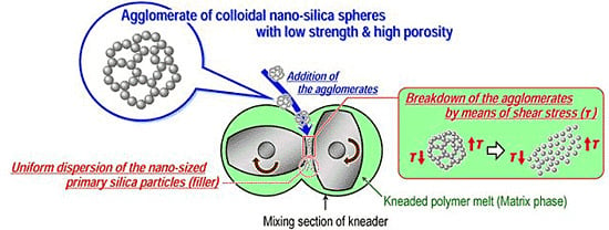
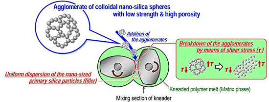
3.1. Concept

3.2. Experimental Techniques and Main Findings of Authors’ Previous Studies
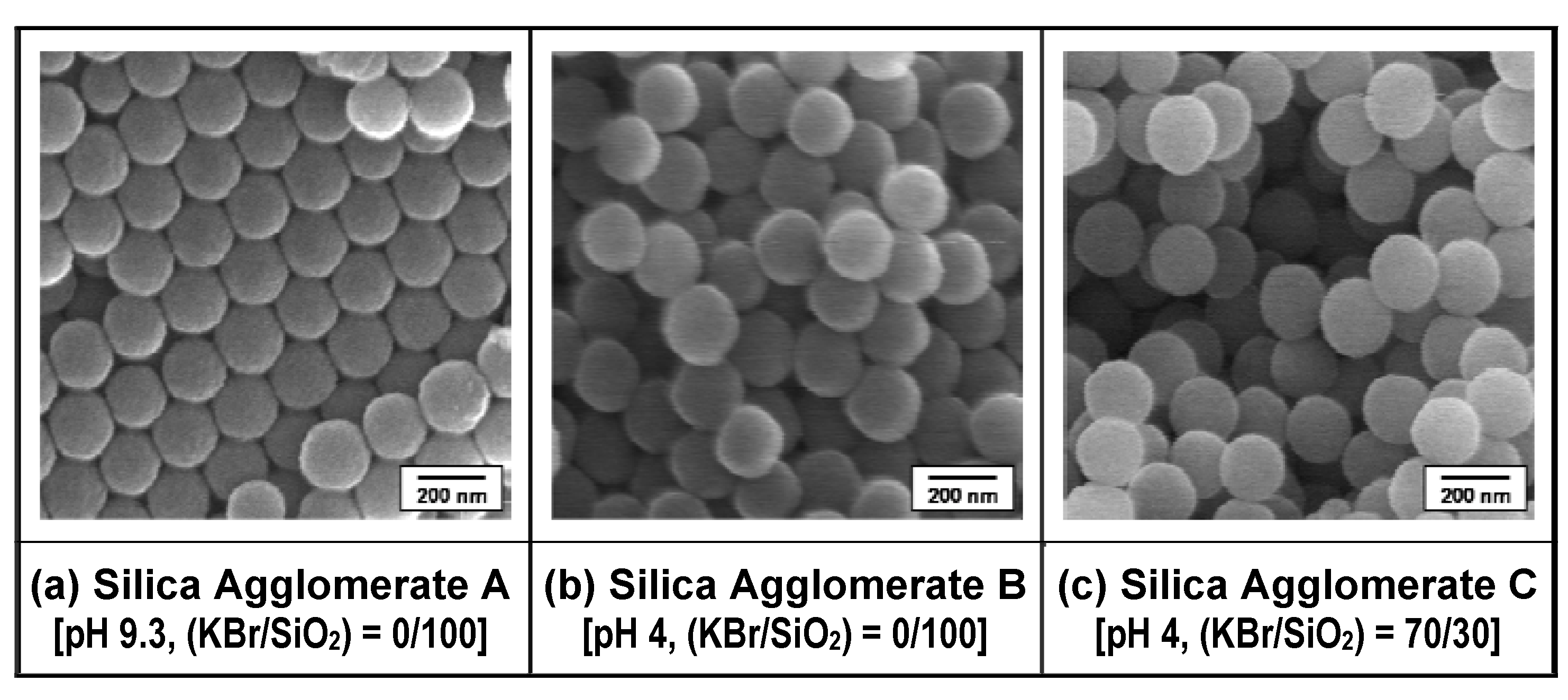
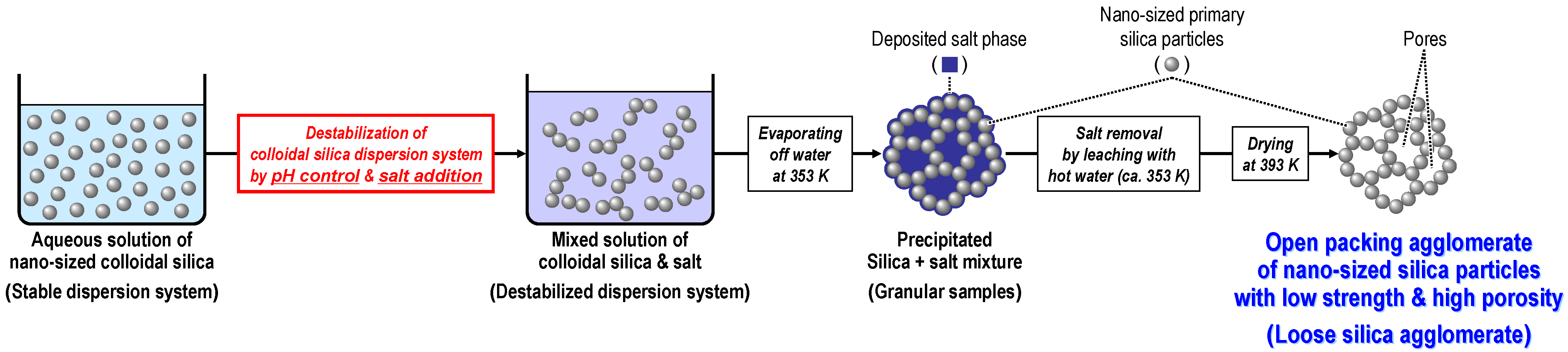
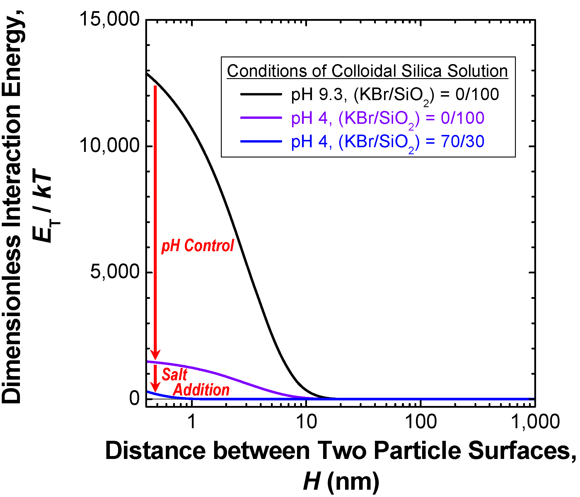
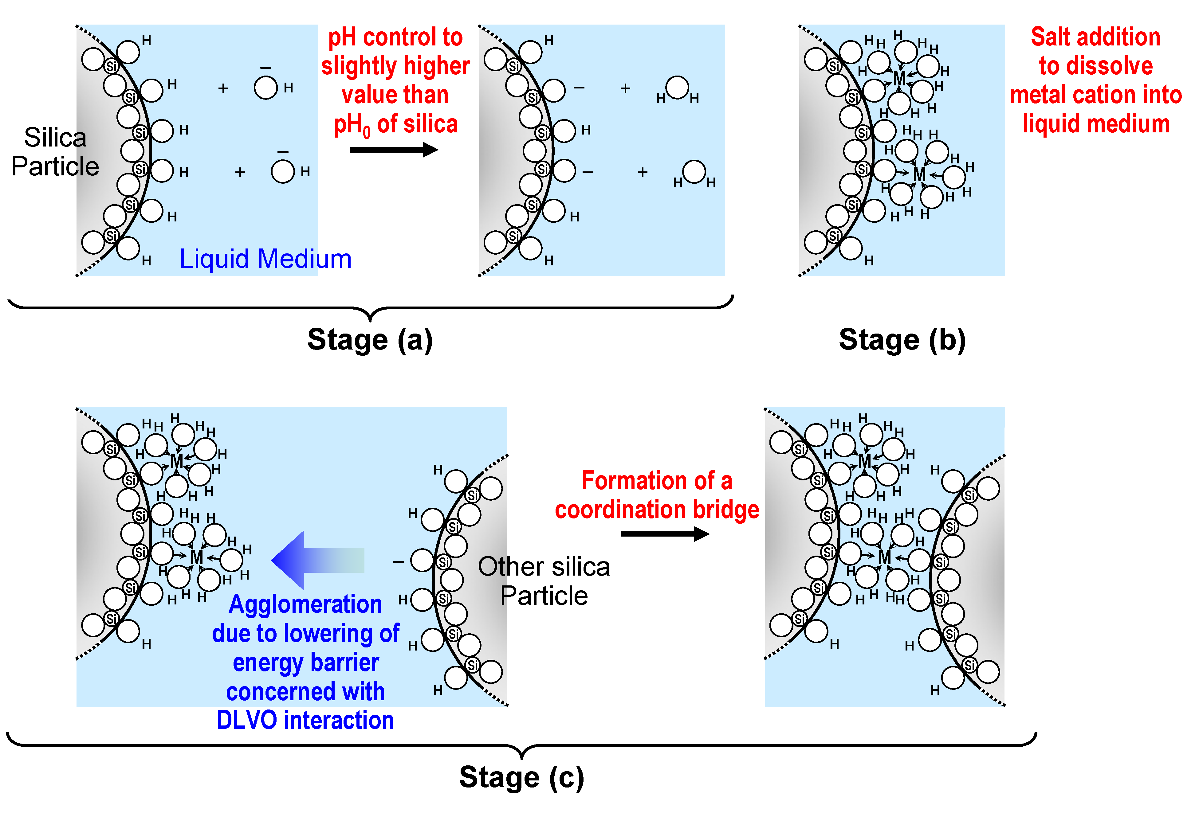
3.2.1. Preparation of loose silica agglomerate in the first stage


| Sample | Pore structure | Mean fracture strength, σf,Silica (MPa) | ||
|---|---|---|---|---|
| Mean pore diameter, DP,Silica (nm) | Standard deviation of pore diameter, σP,Silica (nm) | Porosity, φSilica | ||
| Silica agglomerate A | 40.15 | 14.94 | 0.34 | 3.3 |
| Silica agglomerate B | 51.89 | 19.82 | 0.39 | 0.8 |
| Silica agglomerate C | 60.94 | 26.27 | 0.45 | 0.5 |
| Commercially available product of fine porous silica gel | Unknown | Unknown | 0.75 | 10.0 |

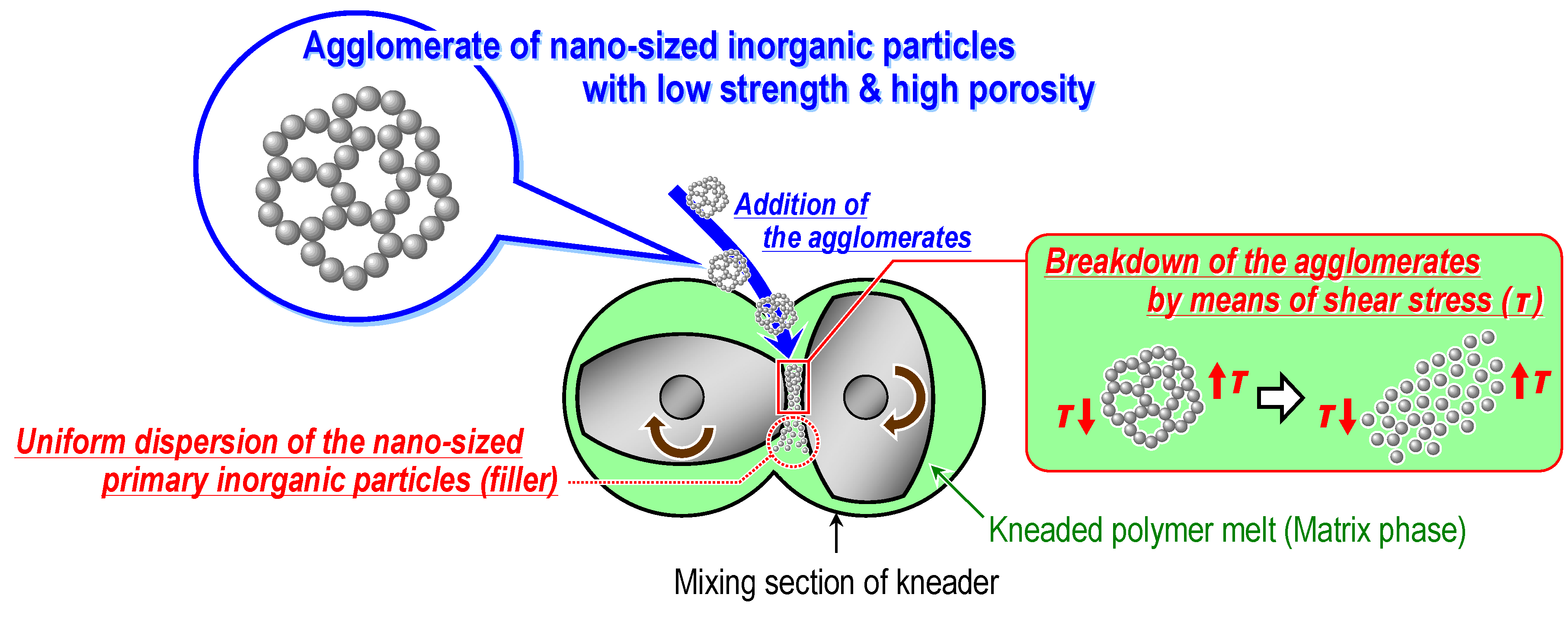
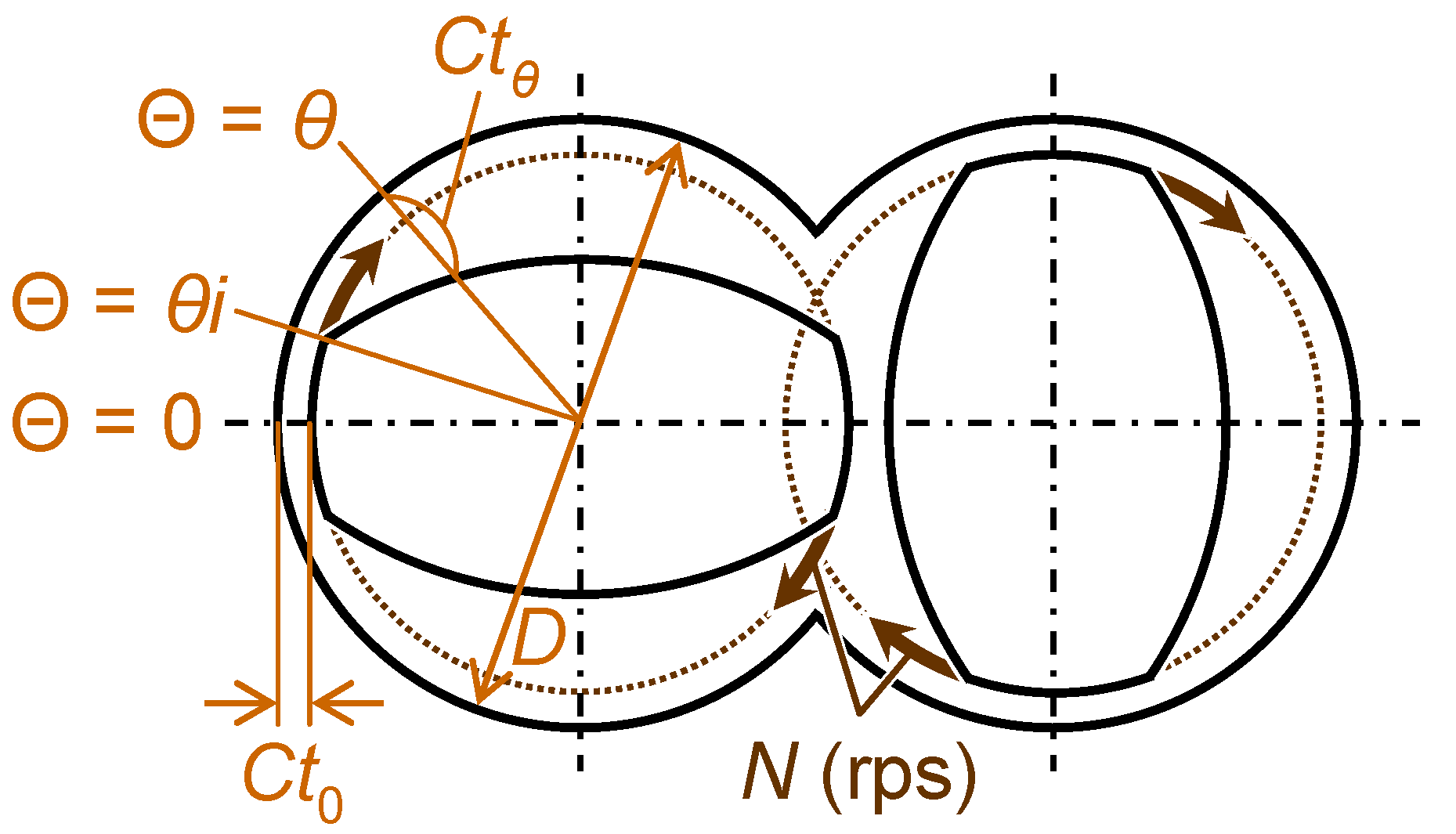
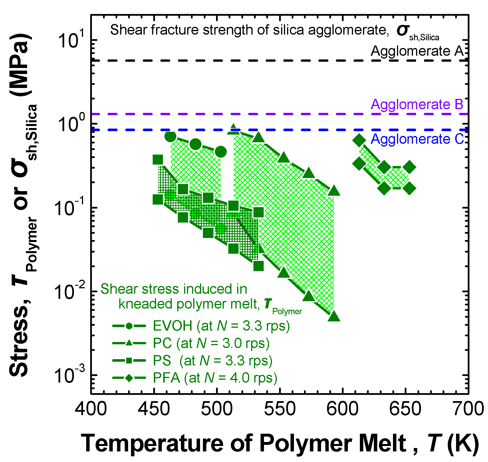
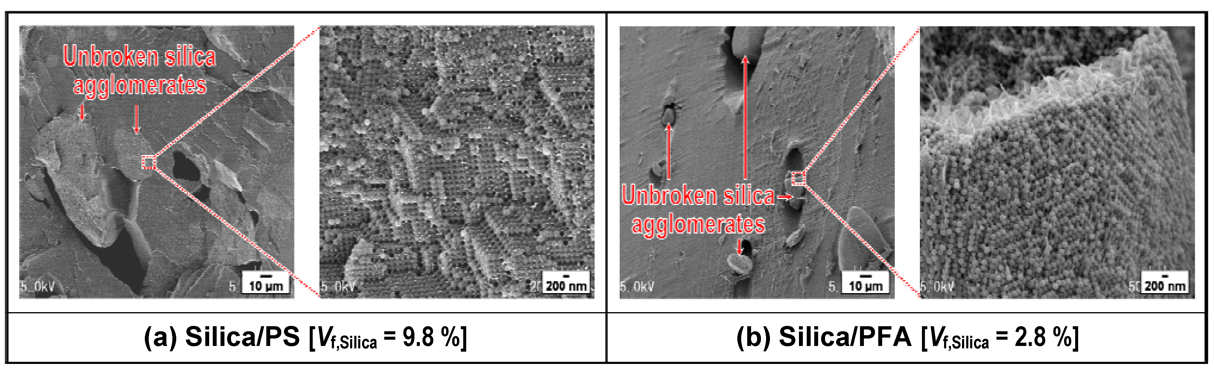
3.2.2. Melt-compounding of polymer matrices with silica agglomerates in the second stage

| Matrix polymer | Volume fraction of silica, Vf,Silica (%) | Melt temp. (K)** | High rotational speed mode | Low rotational speed mode | Number of cycle*** | ||
|---|---|---|---|---|---|---|---|
| Rotational speed (rps) | Time (s) | Rotational speed (rps) | Time (s) | ||||
| EVOH | 2.7 | 463−496 | 3.3 | 20 | 0.3 | 180 | 4 |
| PC | 1.0* | 513−543 | 3.0 | 20 | 0.3 | 180 | 4 |
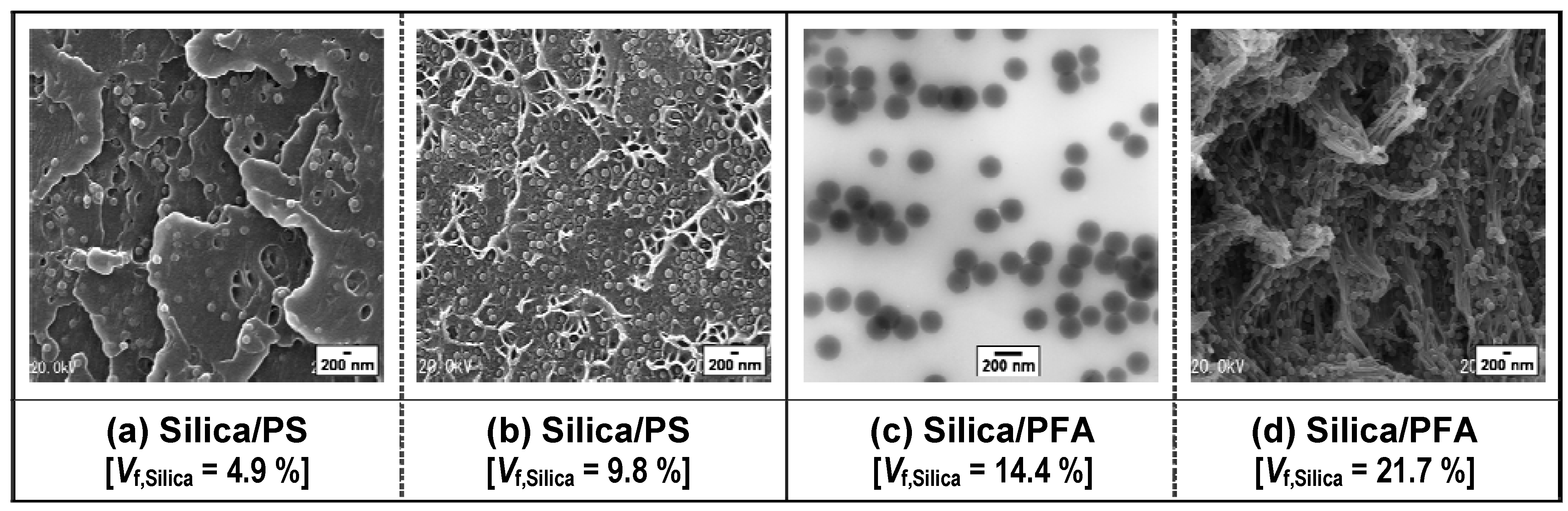
| PS | 2.5, 4.9 | 453−478 | 3.3 | 20 | 0.3 | 180 | 4 |
| PS | 9.8 | 453−483 | 3.3 | 20 | 0.3 | 180 | 4 |
| PFA | 2.8, 14.4 | 613−643 | 4.0 | 20 | 0.3 | 240 | 5 |
| PFA | 27.1 | 618−643 | 3.3 | 20 | 0.3 | 180 | 4 |

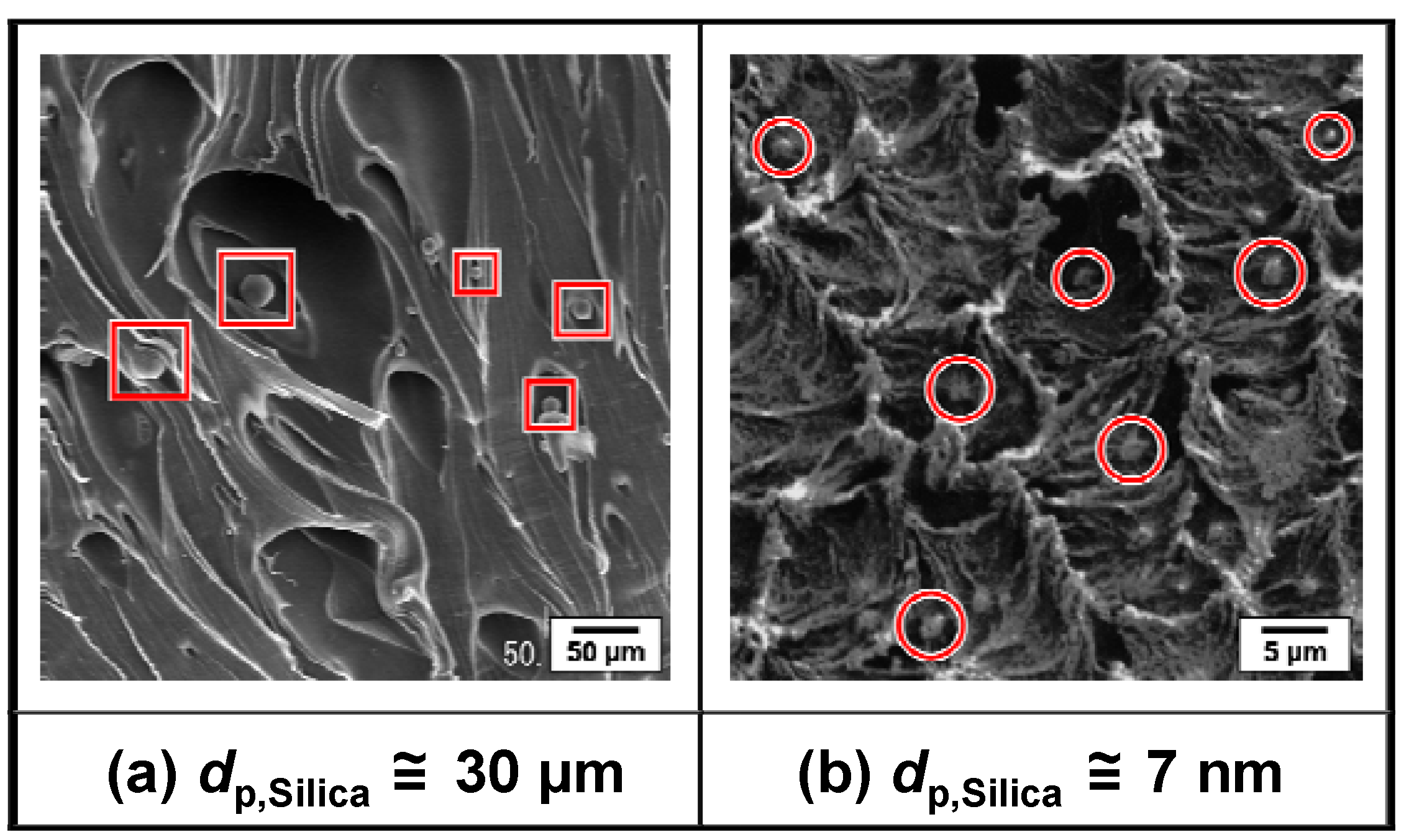
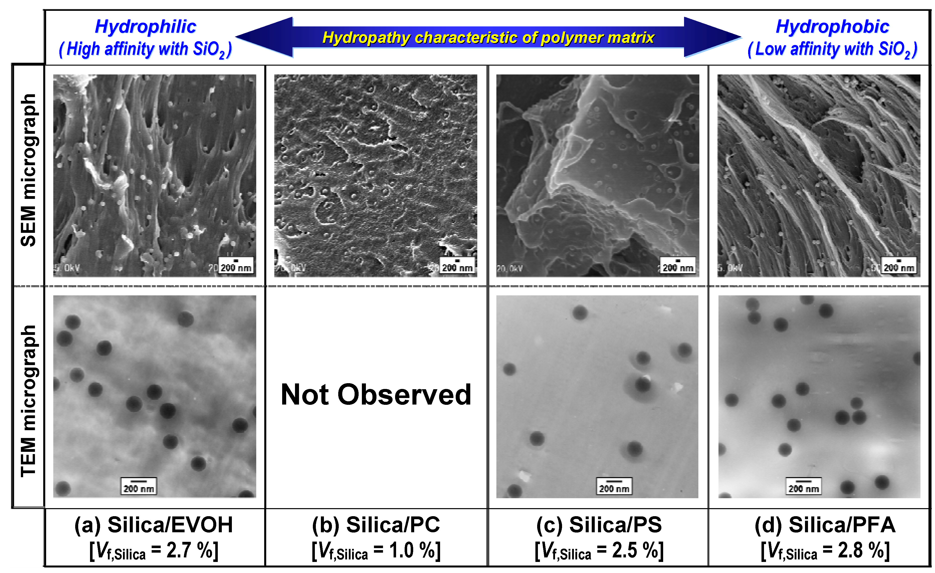
3.2.3. Distribution of primary silica particles in various polymer matrices


4. Summary
Acknowledgements
References and Notes
- Nielsen, L.E.; Landel, R.F. Mechanical Properties of Polymers and Composites, 2nd ed.; Marcel Dekker: New York, NY, USA, 1994. [Google Scholar]
- Ajayan, P.M.; Schadler, L.S.; Braun, P.V. Nanocomposite Science and Technology; Wiley-VCH: Weinheim, Germany, 2003. [Google Scholar]
- Morikawa, A.; Iyoku, Y.; Kakimoto, M.; Imai, Y. Preparation of a new class of polyimide-silica hybrid films by sol-gel process. Polym. J. 1992, 24, 107–113. [Google Scholar]
- Claude, C.; Garetz, B.; Okamoto, Y.; Tripathy, S. The preparation and characterization of organically modified silicates that exhibit nonlinear optical properties. Mater. Lett. 1992, 14, 336–342. [Google Scholar]
- Luther-Davies, B.; Samoc, M.; Woodruff, M. Comparison of the linear and nonlinear optical properties of poly(p-phenylenevinylene)/sol-gel composites derived from tetramethoxysilane and methyltrimethoxysilane. Chem. Mater. 1996, 8, 2586–2594. [Google Scholar]
- Novak, B.M.; Ellsworth, M.W.; Verrier, C. Organic-inorganic nanocomposite materials. Mechanical and thermal properties. Polym. Mater. Sci. Eng. 1994, 70, 266–267. [Google Scholar]
- Schmit, H.; Wolter, H. Organically modified ceramics and their applications. J. Non-Cryst. Solids 1990, 121, 428–435. [Google Scholar]
- Popall, M.; Meyer, H.; Schmidt, H.; Schulz, J. Inorganic-organic composites (ORMOCERs) as structured layers for microelectronics. Mater. Res. Soc. Symp. Proc. 1990, 180, 995–1001. [Google Scholar]
- Glaser, R.H.; Wilkes, G.L. Structure property behavior of polydimethylsiloxane and poly(tetramethylene oxide) modified TEOS based sol-gel materials. V. Effect of titaniumisopropoxide incorporation. Polym. Bull. 1988, 19, 51–57. [Google Scholar]
- Pope, E.J.A.; Mackenzie, J.D. Incorporation of organic dyes in polymer/oxide composites. MRS Bull. 1987, 12, 29–31. [Google Scholar]
- Pope, E.J.A.; Asami, M.; Mackenzie, J.D. Transparent silica gel-PMMA composites. J. Mater. Res. 1989, 4, 1018–1026. [Google Scholar]
- Reetz, M.T.; Zonta, A.; Simpelkamp, J. Efficient heterogeneous biocatalysts by entrapment of lipases in hydrophobic sol-gel materials. Angew. Chem. Int. Ed. Engl. 1995, 34, 301–303. [Google Scholar]
- Harmer, M.A.; Farneth, W.E.; Sun, Q. High surface area Nafion resin/silica nanocomposites: A new class of solid acid catalyst. J. Am. Chem. Soc. 1996, 118, 7708–7715. [Google Scholar]
- Nunes, S.P.; Schultz, J.; Peinemann, K.-V. Silicone membranes with silica nanoparticles. J. Mater. Sci. Lett. 1996, 15, 1139–1141. [Google Scholar]
- Smaïhi, M.; Jermoumi, T.; Marignan, J.; Noble, R.D. Organic-inorganic gas separation membranes: Preparation and characterization. J. Membr. Sci. 1996, 116, 211–220. [Google Scholar]
- Tamaki, R.; Chujo, Y.; Kuraoka, K.; Yazawa, T. Application of organic-inorganic polymer hybrids as selective gas permeation membranes. J. Mater. Chem. 1999, 9, 1741–1746. [Google Scholar]
- Philipp, G.; Schmidt, H. New materials for contact lenses prepared from Si- and Ti-alkoxides by the sol-gel process. J. Non-Cryst. Solids 1984, 63, 283–292. [Google Scholar]
- Takadama, H.; Hashimoto, M.; Takigawa, Y.; Mizuno, M.; Kokubo, T. Effect of melt flow rate of polyethylene on bioactivity and mechanical properties of polyethylene/titania composites. In Bioceramics 16, Key Engineering Materials: Proceedings of the 16th International Symposium on Ceramics in Medicine; Barbosa, M.A., Monteiro, F.J., Correia, R., Leon, B., Eds.; Trans Tech Publications Inc.: Uetikon-Zurich, Switzerland, 2004; Volumes 254–256, pp. 569–572. [Google Scholar]
- Hashimoto, M.; Takadama, H.; Mizuno, M.; Kokubo, T. Enhancement of mechanical strength of TiO2/high-density polyethylene composites for bone repair with silane-coupling treatment. Mater. Res. Bull. 2006, 41, 515–524. [Google Scholar]
- Jakopin, S. Compounding of additives. In Proceedings of 37th Annual SPE Technical Conference (ANTEC 1979 Conference); Society of Plastics Engineers, Inc.: Brookfield, CT, USA, 1979; pp. 987–991. [Google Scholar]
- Ess, J.W.; Hornsby, P.R. Twin-screw extrusion compounding of mineral filled thermoplastics: Dispersive mixing effects. Plast. Rubb. Process Appl. 1987, 8, 147–156. [Google Scholar]
- Mülhaupt, R.; Stricker, F. PP compounds as engineering materials. Kunststoffe 1997, 87, 482–486. [Google Scholar]
- Yang, F.; Nelson, G.L. Polymer/silica nanocomposites prepared via extrusion. Polym. Adv. Technol. 2006, 17, 320–326. [Google Scholar]
- Kalaitzidou, K.; Fukushima, H.; Drzal, L.T. A new compounding method for exfoliated graphite-polypropylene nanocomposites with enhanced flexural properties and lower percolation threshold. Compos. Sci. Technol. 2007, 67, 2045–2051. [Google Scholar]
- Jankong, S.; Srikulkit, K. Preparation of polypropylene/hydrophobic silica nanocomposites. J. Met. Mater. Miner. 2008, 18, 143–146. [Google Scholar]
- Yoshioka, H. Silane coupling agents. J. Adhesion Soc. Jpn. 1985, 21, 252–260. [Google Scholar]
- Plueddemann, E.P. Silane Coupling Agents, 2nd ed.; Plenum Press: New York, NY, USA, 1991. [Google Scholar]
- Nagata, K. 3.7 Mukikei jutenzai -Polymer/mukijutenzai kaimen no seigyo gijutsu- (In Japanese). Adhesion Technol., Jpn. 1997, 17, 54–59. [Google Scholar]
- Ou, Y.; Yang, F.; Chen, J. Interfacial interaction and mechanical properties of nylon 6-potassium titanate composites prepared by in-situ polymerization. J. Appl. Polym. Sci. 1997, 64, 2317–2322. [Google Scholar]
- Yang, F.; Ou, Y.; Yu, Z. Polyamide 6/silica nanocomposites preperaed by in situ polymerization. J. Appl. Polym. Sci. 1998, 69, 355–361. [Google Scholar]
- Ou, Y.; Yang, F.; Yu, Z.-Z. A new conception on the toughness of nylon 6/silica nanocomposite prepared via in situ polymerization. J. Polym. Sci., B 1998, 36, 789–795. [Google Scholar]
- Alexandre, M.; Pluta, M.; Dubois, P.; Jérôe, R. Metallocene catalyzed polymerization of ethylene in the presence of graphite, 1 synthesis and characterization of the composites. Macromol. Chem. Phys. 2001, 202, 2239–2246. [Google Scholar]
- Kaminsky, W.; Wiemann, K. Polypropene/silica-nanocomposites synthesized by in situ polymerization. Expected Mater. Future 2003, 3, 6–12. [Google Scholar]
- Scharlach, K.; Kaminsky, W. New polyolefin-nanocomposites by in situ polymerization with metallocene catalysts. Macromol. Symp. 2008, 261, 10–17. [Google Scholar]
- Chae, D.W.; Kim, B.C. Characterization on polystyrene/zinc oxide nanocomposites prepared from solution mixing. Polym. Adv. Technol. 2005, 16, 846–850. [Google Scholar]
- Pan, W.; Zou, H. Characterization of PAN/ATO nanocomposites prepared by solution blending. Bull. Mater. Sci. 2008, 31, 807–811. [Google Scholar]
- Usuki, A.; Kawasumi, M.; Kojima, Y.; Okada, A.; Kurauchi, T.; Kamigaito, O. Swelling behavior of montmorillonite cation exchanged for ω-amine acid by ε-caprolactam. J. Mater. Res. 1993, 8, 1174–1178. [Google Scholar]
- Fudala, Á.; Pálinkó, I.; Kiricsi, I. Preparation and characterization of hybrid organic-inorganic composite materials using the amphoteric property of amino acids: Amino acid intercalated layered double hydroxide and montmorillonite. Inorg. Chem. 1999, 38, 4653–4658. [Google Scholar]
- Lin, J.J.; Cheng, I.J.; Wang, R.; Lee, R.J. Tailoring basal spacings of montmorillonite by poly(oxyalkylene)diamine intercalation. Macromolecules 2001, 34, 8832–8834. [Google Scholar]
- Bottino, F.A.; Fabbri, E.; Fragalà, I.L.; Malandrino, G.; Orestano, A.; Pilati, F.; Pollicino, A. Polystyrene-clay nanocomposites prepared with polymerizable imidazolium surfactants. Macromol. Rapid. Commun. 2003, 24, 1079–1084. [Google Scholar]
- Usuki, A.; Kojima, Y.; Kawasumi, M.; Okada, A.; Fukushima, Y.; Kurauchi, T.; Kamigaito, O. Synthesis of nylon-6–clay hybrid. J. Mater. Res. 1993, 8, 1179–1183. [Google Scholar]
- Pinnavaia, T.J.; Beall, G.W. (Eds.) Polymer-Clay Nanocomposites; Wiley: New York, NY, USA, 2001.
- Ray, S.S.; Okamoto, M. Polymer/layered silicate nanocomposites: A review from preparation to processing. Prog. Polym. Sci. 2003, 28, 1539–1641. [Google Scholar]
- Shioyama, H. Polymerization of isoprene and styrene in the interlayer spacing of graphite. Carbon 1997, 35, 1664–1665. [Google Scholar]
- Shioyama, H.; Tatsumi, K.; Iwashita, N.; Fujita, K.; Sawada, Y. On the interaction between the potassium-GIC and unsaturated hydrocarbons. Synth. Met. 1998, 96, 229–233. [Google Scholar]
- Ogata, N.; Jimenez, G.; Kawai, H.; Ogihara, T. Structure and thermal/mechanical properties of poly (l-lactide)-clay blend. J. Polym. Sci., B: Polym. Phys. 1997, 35, 389–396. [Google Scholar]
- Ratna, D.; Simon, G.P. Polymer-clay nanocomposites. J. Polym. Mater. 2002, 19, 143–146. [Google Scholar]
- Vaia, R.A.; Ishii, H.; Giannelis, E.P. Synthesis and properties of two-dimensional nanostructures by direct intercalation of polymer melts in layered silicates. Chem. Mater. 1993, 5, 1694–1696. [Google Scholar]
- Vaia, R.A.; Giannelis, E.P. Lattice model of polymer melt intercalation in organically-modified layered silicates. Macromolecules 1997, 30, 7990–7999. [Google Scholar]
- Vaia, R.A.; Giannelis, E.P. Polymer melt intercalation in organically-modified layered silicates: Model predictions and experiment. Macromolecules 1997, 30, 8000–8009. [Google Scholar]
- Reynaud, E.; Jouen, T.; Gauthier, C.; Vigier, G.; Varlet, J. Nanofillers in polymeric matrix: A study on silica reinforced PA6. Polymer 2001, 42, 8759–8768. [Google Scholar]
- Mayer, A.B.R. Formation of noble metal nanoparticles within a polymeric matrix: Nanoparticle features and overall morphologies. Mater. Sci. Eng., C 1998, 6, 155–166. [Google Scholar]
- Nakao, Y. Preparation and characterisation of noble metal solid sols in poly(methyl methacrylate). J. Chem. Soc., Chem. Commun. 1993, 826–828. [Google Scholar]
- Chujo, Y.; Saegusa, T. Organic polymer hybrids with silica gel formed by means of the sol-gel method. Adv. Polym. Sci. 1992, 100, 11–29. [Google Scholar]
- Novak, B.M. Hybrid nanocomposite materials -between inorganic glasses and organic polymers. Adv. Mater. 1993, 5, 422–433. [Google Scholar]
- Haraguchi, K.; Usami, Y.; Yamamura, K.; Matsumoto, S. Morphological investigation of hybrid materials composed of phenolic resin and silica prepared by in situ polymerization. Polymer 1998, 39, 6243–6250. [Google Scholar]
- Chujo, Y.; Tamaki, R. New preparation methods for organic-inorganic polymer hybrids. MRS Bull. 2001, 26, 389–392. [Google Scholar]
- Goda, H.; Frank, C.W. Fluorescence studies of the hybrid composite of segmented-polyurethane and silica. Chem. Mater. 2001, 13, 2783–2787. [Google Scholar]
- Fukuda, T.; Fujiwara, T.; Fujita, H.; Goda, H. Properties of organic nano hybrid composites: Site selective molecular hybrid method. Seikei-Kakou 2005, 17, 109–114. [Google Scholar]
- Tanahashi, M.; Hirose, M.; Lee, J.-C.; Takeda, K. Organic/inorganic nanocomposites prepared by mechanical smashing of agglomerated silica ultrafine particles in molten thermoplastic resin. Polym. Adv. Technol. 2006, 17, 981–990. [Google Scholar]
- Watanabe, Y.; Tanahashi, M.; Takeda, K. Dispersion of silica particles with hydrophilic surfaces into polymer. Kobunshi Ronbunshu 2006, 63, 737–744. [Google Scholar]
- Tanahashi, M.; Hirose, M.; Watanabe, Y.; Lee, J.-C.; Takeda, K. Silica/perfluoropolymer nanocomposites fabricated by direct melt-compounding: A novel method without surface modification on nano-silica. J. Nanosci. Nanotechnol. 2007, 7, 2433–2442. [Google Scholar]
- Tanahashi, M.; Watanabe, Y.; Fujisawa, T. Fabrication and crystallization temperature of silica/polypropylene nanocomposites by simple method without any hydrophobic treatment of nano-silica surfaces. J. Soc. Mater. Sci., Jpn. 2009, 58, 408–415. [Google Scholar]
- Tanahashi, M. Silica biryushi bunsan niyoru fukugo kobunshi zairyo heno kikaiteki-netsuteki tokusei oyobi iseikeikakosei no fuyo. In Silica Biryushi no Tokusei to Hyomen Kaishitsu oyobi Bunsan-Gyosyu no Seigyo; (In Japanese). Technical Information Institute Co., Ltd.: Tokyo, Japan, 2009; pp. 317–337. [Google Scholar]
- Lee, J-.C.; Takeda, K.; Tanahashi, M.; Kanayama, N.; Matsuda, N.; Hirose, M. Inorganic particulate agglomerate and its producing method. Japanese Pat. Appl. JPA 2006–213577.
- Lee, J-.C.; Takeda, K.; Tanahashi, M.; Kanayama, N.; Matsuda, N.; Hirose, M. Thermoplastic-resin composite composition, process for producing the same, and use thereof. PCT International Patent WO2006/082880.
- Carotenuto, G.; Her, Y.-S.; Matijević, E. Preparation and characterization of nanocomposite thin films for optical devices. Ind. Eng. Chem. Res. 1996, 35, 2929–2932. [Google Scholar]
- Andrews, R.; Jaques, D.; Quian, D.; Rantell, T. Multiwall carbon nanotubes: Synthesis and application. Acc. Chem. Res. 2002, 35, 1008–1017. [Google Scholar]
- Preghenella, M.; Pegoretti, A.; Migliaresi, C. Thermo-mechanical characterization of fumed silica-epoxy nanocomposites. Polymer 2005, 46, 12065–12072. [Google Scholar]
- Anand, K.A.; Agarwal, U.S.; Nisalc, A.; Joseph, R. PET-SWNT nanocomposites through ultrasound assisted dissolution-evaporation. Eur. Polym. J. 2007, 43, 2279–2285. [Google Scholar]
- Manas-Zloczower, I.; Nir, A.; Tadmor, Z. Dispersive mixing in internal mixers -A theoretical model based on agglomerate rupture. Rubber Chem. Technol. 1982, 55, 1250–1285. [Google Scholar]
- Shiga, S.; Furuta, M. Processability of EPR in an internal mixter (II) -Morphological changes of carbon black agglomerates during mixing. Rubber Chem. Technol. 1985, 58, 1–22. [Google Scholar]
- Palmgren, H. Processing conditions in the batch-operated internal mixer. Rubber Chem. Technol. 1975, 48, 462–494. [Google Scholar]
- Bolen, W.R.; Colwell, R.E. Intensive mixing. SPE J. 1958, 14, 24–28. [Google Scholar]
- Tanahashi, M.; Watanabe, Y.; Lee, J.-C.; Takeda, K.; Fujisawa, T. Melt flow and mechanical properties of silica/perfluoropolymer nanocomposites fabricated by direct melt-compounding without surface modification on nano-silica. J. Nanosci. Nanotechnol. 2009, 9, 539–549. [Google Scholar]
- Rumpf, H. The strength of granules and agglomerates. In Agglomeration; Knepper, W.A., Ed.; Interscience: New York, NY, USA, 1962; pp. 379–418. [Google Scholar]
- Derjaguin, B.V.; Rabinovich, Y.I.; Churaev, N.V. Direct measurement of molecular forces. Nature 1978, 272, 313–318. [Google Scholar]
- Hough, D.B.; White, L.R. The calculation of Hamaker constants from Lifshitz theory with applications to wetting phenomena. Adv. Colloid Interface Sci. 1980, 14, 3–41. [Google Scholar]
- Israelachvili, J.N. Intermolecular and Surface Forces, 2nd ed.; Academic Press: London, UK, 1992. [Google Scholar]
- Bowling, R.A. A theoretical review of particle adhesion. In Particles on Surfaces 1: Detection, Adhesion, and Removal; Mittal, K.L., Ed.; Plenum Press: New York, NY, USA, 1988; pp. 129–142. [Google Scholar]
- Arai, F.; Ando, D.; Fukuda, T.; Nonoda, Y.; Oota, T. Micro manipulation based on micro physics -Strategy based on attractive force reduction and stress measurement. In Proceedings of the 1995 IEEE/RSJ International Conference on Intelligent Robots and Systems (IROS’95); IEEE Computer Society Press: Los Alamitos, CA, USA, 1995; Volume 2, pp. 236–241. [Google Scholar]
- Higashitani, K. Ekichu ni okeru bunsan. In Engineering System for Fine Particles, Fundamental Technology I.; Yanagida, H., Ed.; Fuji Technosystem: Tokyo, Japan, 2001; pp. 398–402. [Google Scholar]
- Okuyama, K.; Higashitani, K. Agglomeration (Coagulation). In Powder Technology Handbook, 3rd ed.; Masuda, H., Higashitani, K., Yoshida, H., Eds.; CRC Press: Boca Raton, FL, USA, 2006; pp. 183–197. [Google Scholar]
- Iler, R.K. The Chemistry of Silica: Solubility, Polymerization, Colloid and Surface Properties, and Biochemistry; Wiley-Interscience: New York, NY, USA, 1979. [Google Scholar]
- Suetsugu, Y.; Sato, A. Ultrasonic mixing: Visualization of agglomerate dispersion in polymer melts. Seikei-Kakou 2006, 18, 807–812. [Google Scholar]
- Derjaguin, B.V.; Landau, L. Theory of the stability of strongly charged lyophobic sols and of the adhesion of strongly charged particles in solution of electrolytes. Acta Physicochim. URSS 1941, 14, 633–662. [Google Scholar]
- Verwey, E.J.W.; Overbeek, J.Th.G. Theory of Stability of Lyophobic Colloids; Elsevier: Amsterdam, The Netherlands, 1948. [Google Scholar]
- Hamaker, H.C. The London-van der Waals attraction between spherical particles. Physica 1937, 4, 1058–1072. [Google Scholar]
- Hunter, R.J. Foundations of Colloid Science, 2nd ed.; Oxford University Press: Oxford, UK, 2001. [Google Scholar]
- Healy, T.W.; Fuerstenau, D.W. The oxide-water interface Interrelation of the zero point of charge and the heat of immersion. J. Colloid Sci. 1965, 20, 376–386. [Google Scholar]
- Masuda, H.; Adachi, M.; Higashitani, K. Taiden gensho. J. Soc. Powder Technol., Jpn. 1985, 22, 231–244. [Google Scholar]
- Deckman, H.W.; Dunsmuir, J.H. Natural lithography. Appl. Phys. Lett. 1982, 41, 377–379. [Google Scholar]
- Denkov, N.D.; Velev, O.D.; Kralchevski, P.A.; Ivanov, I.B.; Yoshimura, H.; Nagayama, K. Two-dimensional crystallization. Nature 1993, 361, 26. [Google Scholar]
- Masuda, Y.; Itoh, T.; Koumoto, K. Self-assembly and micropatterning of spherical-particle assemblies. Adv. Mater. 2005, 17, 841–845. [Google Scholar]
- Masuda, Y.; Itoh, T.; Koumoto, K. Self-assembly patterning of silica colloidal crystals. Langmuir 2005, 21, 4478–4481. [Google Scholar]
- Tanahashi, M.; Watanabe, Y.; Kawaguchi, Y.; Takeda, K. Surface conditions of nano-sized inorganic particles and pore structure control of their agglomerates. J. Jpn. Inst. Metals 2006, 70, 365–373. [Google Scholar]
- Takase, H.; Mikata, Y.; Matsuda, S.; Murakami, A. Dispersion of carbon-nanotubes in a polymer matrix by a twin-screw extruder. Seikei-Kakou 2002, 14, 126–131. [Google Scholar]
- Nishimatsu, Y. Ganseki kyoudo no hyoujun shiken hou. J. Min. Metall. Inst. Jpn. 1965, 81, 563–570. [Google Scholar]
- Hiramatsu, Y.; Oka, Y.; Kiyama, H. Rapid determination of the tensile strength of rocks with irregular test pieces. J. Min. Metall. Inst. Jpn. 1965, 81, 1024–1030. [Google Scholar]
- Noguchi, T.; Magario, A.; Fukazawa, S.; Shimizu, S.; Beppu, J.; Seki, M.; Nagata, K.; Iwabuki, H.; Nishi, T. Structure and properties for carbon nanofiber/elastomer composites. Polym. Prepr., Jpn. 2003, 52, 1785–1786. [Google Scholar]
© 2010 by the authors; licensee Molecular Diversity Preservation International, Basel, Switzerland. This article is an open-access article distributed under the terms and conditions of the Creative Commons Attribution license (http://creativecommons.org/licenses/by/3.0/).
Share and Cite
Tanahashi, M. Development of Fabrication Methods of Filler/Polymer Nanocomposites: With Focus on Simple Melt-Compounding-Based Approach without Surface Modification of Nanofillers. Materials 2010, 3, 1593-1619. https://doi.org/10.3390/ma3031593
Tanahashi M. Development of Fabrication Methods of Filler/Polymer Nanocomposites: With Focus on Simple Melt-Compounding-Based Approach without Surface Modification of Nanofillers. Materials. 2010; 3(3):1593-1619. https://doi.org/10.3390/ma3031593
Chicago/Turabian StyleTanahashi, Mitsuru. 2010. "Development of Fabrication Methods of Filler/Polymer Nanocomposites: With Focus on Simple Melt-Compounding-Based Approach without Surface Modification of Nanofillers" Materials 3, no. 3: 1593-1619. https://doi.org/10.3390/ma3031593