Improved Performance of Graphene in Heat Dissipation when Combined with an Orientated Magnetic Carbon Fiber Skeleton under Low-Temperature Thermal Annealing


Abstract
:
1. Introduction
2. Materials and Methods
2.1. Materials
2.2. Preparation of GO and MCF
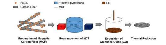
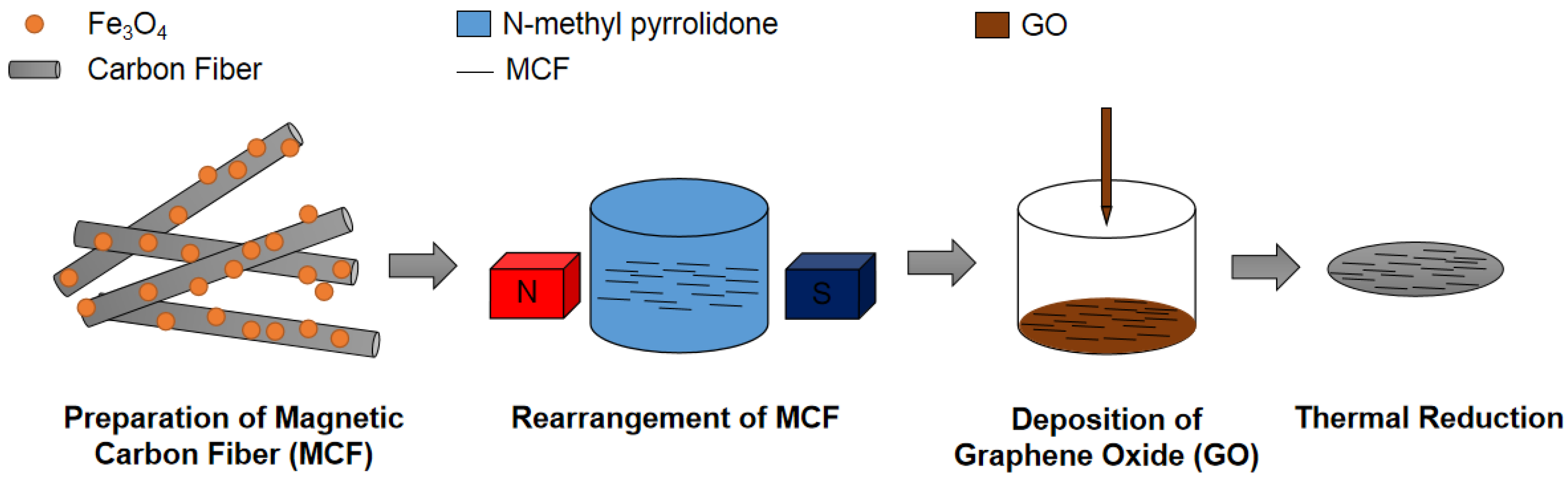
2.3. Preparation of the rGO/MCF Film
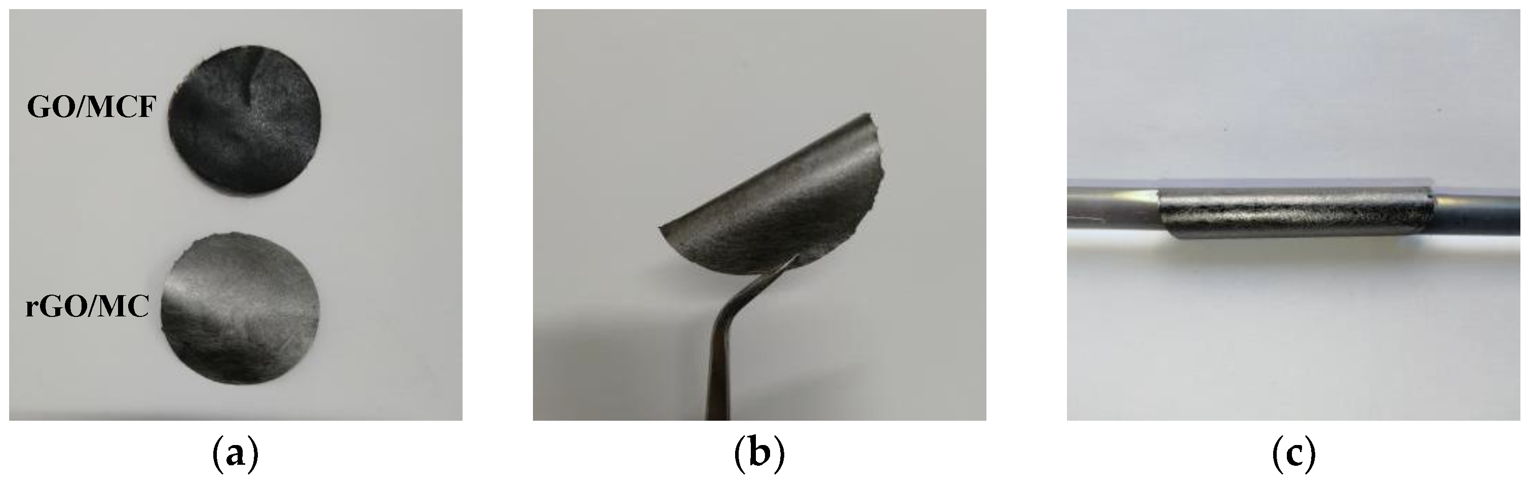
2.4. Characterization
3. Results
4. Conclusions
Supplementary Materials
Author Contributions
Funding
Conflicts of Interest
References
- Lehman, K. Reviews of science for science librarians: Graphene. Sci. Technol. Libr. 2011, 30, 132–142. [Google Scholar] [CrossRef]
- Ferreira, F.V.; Cividanes, L.D.S.; Brito, F.S.; de Meneze, B.R.C.; Franceschi, W.; Simonetti, E.A.N.; Thim, G.P. Functionalization of Graphene and Applications. In Functionalizing Graphene and Carbon Nanotubes, 2nd ed.; Springer: Cham, Germany, 2016; pp. 1–29. [Google Scholar]
- Galiotis, C.; Frank, O.; Koukaras, E.N.; Sfyris, D. Graphene mechanics: Current status and perspectives. Annu. Rev. Chem. Biomol. Eng. 2015, 6, 121–140. [Google Scholar] [CrossRef] [PubMed]
- Li, Y.; Yang, J.; Song, J. Nano energy system model and nanoscale effect of graphene battery in renewable energy electric vehicle. Renew. Sustain. Energy Rev. 2017, 69, 652–663. [Google Scholar] [CrossRef]
- Yang, Z.; Tian, J.; Yin, Z.; Cui, C.; Qian, W.; Wei, F. Carbon nanotube- and graphene-based nanomaterials and applications in high-voltage supercapacitor: A review. Carbon 2019, 141, 467–480. [Google Scholar] [CrossRef]
- Nag, A.; Mitra, A.; Mukhopadhyay, S.C. Graphene and its sensor-based applications: A review. Sens. Actuators A Phys. 2018, 270, 177–194. [Google Scholar] [CrossRef]
- Zhu, R.H.; Miao, J.Y.; Liu, J.L.; Chen, L.X.; Guo, J.C.; Hua, C.Y.; Ding, T.; Lian, H.K.; Li, C.M. High temperature thermal conductivity of free-standing diamond films prepared by DC arc plasma jet CVD. Diam. Relat. Mater. 2014, 50, 55–59. [Google Scholar] [CrossRef]
- Han, Z.D.; Fina, A. Thermal conductivity of carbon nanotubes and their polymer nanocomposites: A review. Prog. Polym. Sci. 2011, 36, 914–944. [Google Scholar] [CrossRef] [Green Version]
- Namasivayam, M.; Shapter, J. Factors affecting carbon nanotube fillers towards enhancement of thermal conductivity in polymer nanocomposites: A review. J. Compos. Mater. 2017, 51, 3657–3668. [Google Scholar] [CrossRef]
- Balandin, A.A.; Ghosh, S.; Bao, W.Z.; Calizo, I.; Teweldebrhan, D.; Miao, F.; Lau, C.N. Superior thermal conductivity of single-layer graphene. Nano Lett. 2008, 8, 902–907. [Google Scholar] [CrossRef]
- Yi, M.; Shen, Z.G. A review on mechanical exfoliation for the scalable production of graphene. J. Mater. Chem. A Mater. 2015, 3, 11700–11715. [Google Scholar] [CrossRef]
- Parviz, D.; Irin, F.; Shah, S.A.; Das, S.; Sweeney, C.B.; Green, M.J. Challenges in liquid-phase exfoliation, processing, and assembly of pristine graphene. Adv. Mater. 2016, 28, 8796–8818. [Google Scholar] [CrossRef]
- Guex, L.G.; Sacchi, B.; Peuvot, K.F.; Andersson, R.L.; Pourrahimi, A.M.; Strom, V.; Farris, S.; Olsson, R.T. Experimental review: Chemical reduction of graphene oxide (GO) to reduced graphene oxide (rGO) by aqueous chemistry. Nanoscale 2017, 9, 9562–9957. [Google Scholar] [CrossRef]
- Aunkor, M.T.H.; Mahbubul, I.M.; Saidur, R.; Metselaar, H.S.C. The green reduction of graphene oxide. RSC Adv. 2016, 6, 27807–27828. [Google Scholar] [CrossRef]
- Chen, J.; Yao, B.W.; Li, C.; Shi, G.Q. An improved hummers method for eco-friendly synthesis of graphene oxide. Carbon 2013, 64, 225–229. [Google Scholar] [CrossRef]
- Munoz, R.; Gomez-Aleixandre, C. Review of CVD synthesis of graphene. Chem. Vapor Depos. 2013, 19, 297–322. [Google Scholar] [CrossRef]
- Tang, B.; Hu, G.; Gao, H.; Hai, L. Application of graphene as filler to improve thermal transport property of epoxy resin for thermal interface materials. Int. J. Heat Mass Transf. 2015, 85, 420–429. [Google Scholar] [CrossRef]
- Ghozatloo, A.; Rashidi, A.; Shariaty-Niassar, M. Convective heat transfer enhancement of graphene nanofluids in shell and tube heat exchanger. Exp. Therm. Fluid Sci. 2014, 53, 136–141. [Google Scholar] [CrossRef]
- Wang, N.; Samani, M.K.; Li, H.; Dong, L.; Zhang, Z.; Su, P.; Chen, S.; Chen, J.; Huang, S.; Yuan, G.; et al. Tailoring the thermal and mechanical properties of graphene film by structural engineering. Small 2018, 14, 1801346. [Google Scholar] [CrossRef]
- Xin, G.; Sun, H.; Hu, T.; Fard, H.R.; Sun, X.; Koratkar, N.; Borca-Tasciuc, T.; Lian, J. Large-area freestanding graphene paper for superior thermal management. Adv. Mater. 2014, 26, 4521–4526. [Google Scholar] [CrossRef]
- Peng, L.; Xu, Z.; Liu, Z.; Guo, Y.; Li, P.; Gao, C. Ultrahigh thermal conductive yet superflexible graphene films. Adv. Mater. 2017, 29, 1700589. [Google Scholar] [CrossRef]
- Shen, B.; Zhai, W.; Zheng, W. Ultrathin Flexible graphene film: An excellent thermal conducting material with efficient EMI shielding. Adv. Funct. Mater. 2014, 24, 4542–4548. [Google Scholar] [CrossRef]
- Galashev, A.E.; Rakhmanova, O.R. Mechanical and thermal stability of graphene and graphene-based materials. Phys. Uspekhi 2014, 57, 970–989. [Google Scholar] [CrossRef]
- Zhang, Y.; Pan, C. Measurements of mechanical properties and number of layers of graphene from nano-indentation. Diam. Relat. Mater. 2012, 24, 1–5. [Google Scholar] [CrossRef]
- Zhao, Y.H.; Zhang, Y.F.; Bai, S.L. High thermal conductivity of flexible polymer composites due to synergistic effect of multilayer graphene flakes and graphene foam. Compos. Part A Appl. Sci. Manuf. 2016, 85, 148–155. [Google Scholar] [CrossRef]
- Lv, P.; Tan, X.W.; Yu, K.H.; Zheng, R.L.; Zheng, J.J.; Wei, W. Super-elastic graphene/carbon nanotube aerogel: A novel thermal interface material with highly thermal transport properties. Carbon 2016, 99, 222–228. [Google Scholar] [CrossRef]
- Shahil, K.M.F.; Balandin, A.A. Graphene-multilayer graphene nanocomposites as highly efficient thermal interface materials. Nano Lett. 2012, 12, 861–867. [Google Scholar] [CrossRef]
- Zhang, J.; Shi, G.; Jiang, C.; Ju, S.; Jiang, D. 3D bridged carbon nanoring/graphene hybrid paper as a high-performance lateral heat spreader. Small 2015, 11, 6197–6204. [Google Scholar] [CrossRef]
- Kong, Q.Q.; Liu, Z.; Gao, J.G.; Chen, C.M.; Zhang, Q.; Zhou, G.; Tao, Z.; Zhang, X.; Wang, M.; Li, F.; et al. Hierarchical graphene-carbon fiber composite as a flexible lateral heat spreader. Adv. Funct. Mater. 2014, 24, 4222–4228. [Google Scholar] [CrossRef]
- Song, N.J.; Chen, C.M.; Lu, C.; Liu, Z.; Kong, Q.Q.; Cai, R. Thermally reduced graphene oxide films as flexible lateral heat spreaders. J. Mater. Chem. A 2014, 2, 16563–16568. [Google Scholar] [CrossRef]
- Bekyarova, E.; Thostenson, E.T.; Yu, A.; Kim, H.; Gao, J.; Tang, J.; Hahn, H.T.; Chou, T.; Itkis, M.E.; Haddon, R.C. Multiscale carbon nanotube-carbon fiber reinforcement for advanced epoxy composites. Langmuir 2007, 23, 3970–3974. [Google Scholar] [CrossRef]
- Feng, J.; Zhang, C.; Feng, J. Carbon fiber reinforced carbon aerogel composites for thermal insulation prepared by soft reinforcement. Mater. Lett. 2012, 67, 266–268. [Google Scholar] [CrossRef]
- Kalantari, K.; Bin, A.M.; Shameli, K.; Khandanlou, R. Synthesis of talc/Fe3O4 magnetic nanocomposites using chemical co-precipitation method. Int. J. Nanomed. 2013, 8, 1817–1823. [Google Scholar] [Green Version]
- Hu, D.; Gong, W.; Di, J.; Li, D.; Li, R.; Lu, W. Strong graphene-interlayered carbon nanotube films with high thermal conductivity. Carbon 2017, 118, 659–665. [Google Scholar] [CrossRef]
- Malard, L.M.; Pimenta, M.A.; Dresselhaus, G.; Dresselhaus, M.S. Raman Spectroscopy in Graphene. Phys. Rep. 2009, 473, 51–87. [Google Scholar] [CrossRef]
- Eigler, S.; Dotzer, C.; Hirsch, A. Visualization of defect densities in reduced graphene oxide. Carbon 2012, 50, 3666–3673. [Google Scholar] [CrossRef]
- Lucchese, M.M.; Stavale, F.; Ferreira, E.H.M.; Vilani, C.; Moutinho, M.V.O.; Capaz, R.B.; Achete, C.A.; Jorio, A. Quantifying ion-induced defects and Raman relaxation length in graphene. Carbon 2010, 48, 1592–1597. [Google Scholar] [CrossRef]
- Shi, P.C.; Guo, J.P.; Liang, X.; Cheng, S.; Zheng, H.; Wang, Y.; Chen, C.H.; Xiang, H.F. Large-scale production of high-quality graphene sheets by a non-electrified electrochemical exfoliation method. Carbon 2018, 126, 507–513. [Google Scholar] [CrossRef]
- Nika, D.L.; Balandin, A.A. Two-dimensional phonon transport in graphene. J. Phys. Condens. Matter 2012, 24, 233203. [Google Scholar] [CrossRef] [Green Version]
- Seol, J.H.; Jo, I.; Moore, A.L.; Lindsay, L.; Aitken, Z.H.; Pettes, M.T.; Li, X.; Yao, Z.; Huang, R.; Broido, D.; et al. Two-dimensional phonon transport in supported graphene. Science 2010, 328, 213–216. [Google Scholar] [CrossRef]
- Stobinski, L.; Lesiak, B.; Malolepszy, A.; Mazurkiewicz, M.; Mierzwa, B.; Zemek, J.; Jiricek, P.; Bieloshapka, I. Graphene oxide and reduced graphene oxide studied by the XRD, TEM and electron spectroscopy methods. J. Electron. Spectros. Relat. Phenom. 2014, 195, 145–154. [Google Scholar] [CrossRef]


| Name | Origin | Purity (%) |
|---|---|---|
| Graphite flakes | Tengshengda Tansu Jixie Co. Ltd., Qingdao, China | 99.9 |
| PCF | Anjie Composite Material Co. Ltd., Haining, China | 99.9 |
| H2SO4 | Guangzhou Chemical Reagents Factory, Guangzhou, China | A.R. |
| KMnO4 | Guangzhou Chemical Reagents Factory, Guangzhou, China | A.R. |
| H2O2 | Guangzhou Chemical Reagents Factory, Guangzhou, China | 30 |
| HCl | Guangzhou Chemical Reagents Factory, Guangzhou, China | G.R. |
| Acetone | Guangzhou Chemical Reagents Factory, Guangzhou, China | A.R. |
| HNO3 | Guangzhou Chemical Reagents Factory, Guangzhou, China | A.R. |
| FeCl3 | Guangzhou Chemical Reagents Factory, Guangzhou, China | A.R. |
| FeCl2 | Guangzhou Chemical Reagents Factory, Guangzhou, China | A.R. |
| NMP | Guangzhou Chemical Reagents Factory, Guangzhou, China | 99 |
| Name | Density (g/cm3) | Heat Capacity (J/(g·K)) | Thermal Diffusion Coefficient (mm2/s) | Thermal Conductivity (W/m·K) |
|---|---|---|---|---|
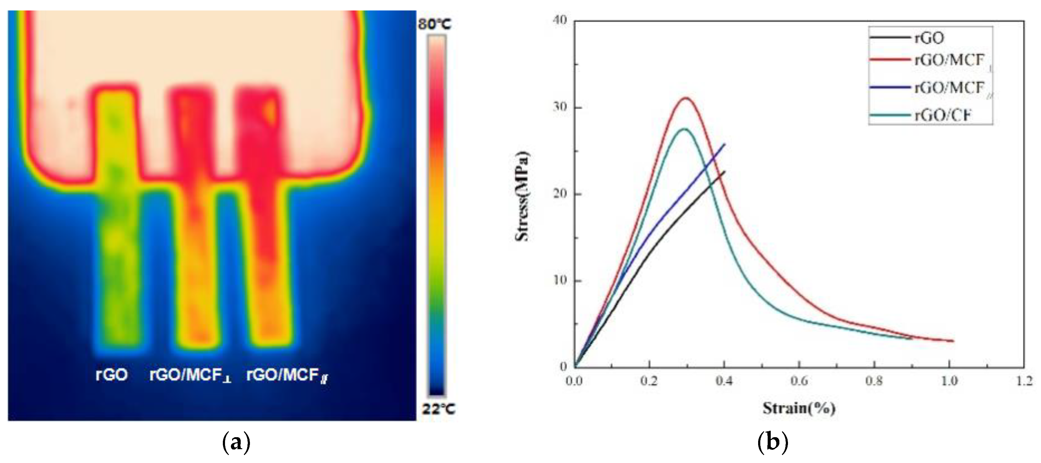
| rGO | 0.42 | 0.64 | 57.4 | 15.4 ± 0.8 |
| rGO/MCF⊥ | 0.51 | 0.71 | 1658.3 | 600.4 ± 30.0 |
| rGO/MCF∥ | 0.51 | 0.71 | 1532.4 | 554.9 ± 27.7 |
© 2019 by the authors. Licensee MDPI, Basel, Switzerland. This article is an open access article distributed under the terms and conditions of the Creative Commons Attribution (CC BY) license (http://creativecommons.org/licenses/by/4.0/).
Share and Cite
Li, J.; Lei, R.; Lai, J.; Chen, X.; Li, Y. Improved Performance of Graphene in Heat Dissipation when Combined with an Orientated Magnetic Carbon Fiber Skeleton under Low-Temperature Thermal Annealing. Materials 2019, 12, 954. https://doi.org/10.3390/ma12060954
Li J, Lei R, Lai J, Chen X, Li Y. Improved Performance of Graphene in Heat Dissipation when Combined with an Orientated Magnetic Carbon Fiber Skeleton under Low-Temperature Thermal Annealing. Materials. 2019; 12(6):954. https://doi.org/10.3390/ma12060954
Chicago/Turabian StyleLi, Jing, Rubai Lei, Jinfeng Lai, Xuyang Chen, and Yang Li. 2019. "Improved Performance of Graphene in Heat Dissipation when Combined with an Orientated Magnetic Carbon Fiber Skeleton under Low-Temperature Thermal Annealing" Materials 12, no. 6: 954. https://doi.org/10.3390/ma12060954