Microstructure and Mechanical Properties of Si3N4-Fe3Si Composites Prepared by Gas-Pressure Sintering

Science and Technology on Thermostructural Composite Materials Laboratory, Northwestern Polytechnical University, Xi’an 710072, Shaanxi, China
*
Author to whom correspondence should be addressed.
Materials 2018, 11(7), 1206; https://doi.org/10.3390/ma11071206
Submission received: 29 May 2018
/
Revised: 29 June 2018
/
Accepted: 3 July 2018
/
Published: 13 July 2018
Abstract
:Si3N4-Fe3Si composites were prepared using Fe-Si3N4 as the source of Fe3Si by gas-pressure sintering. By adding different amounts of Fe-Si3N4 into the starting powders, Si3N4-Fe3Si composites with various Fe3Si phase contents were obtained. The microstructure and mechanical properties of the composites were investigated. With the increase of Fe-Si3N4 contents, the content and particle size of Fe3Si both increased. When more than 60 wt. % Fe-Si3N4 were added, the abnormal growth of Fe3Si particles occurred and oversized Fe3Si particles appeared, leading to non-uniform microstructures and worse mechanical properties of the composites. It has been found that Fe3Si particles could toughen the composites through particle pull-out, interface debonding, crack deflection, and particle bridging. Uniform microstructure and improved mechanical properties (flexural strength of 354 MPa and fracture toughness of 8.4 MPa·m1/2) can be achieved for FSN40.
1. Introduction
Si3N4 is one of the most promising engineering ceramics with high strength, high hardness, good oxidation, and corrosion resistance—even at high temperature. It is also an irreplaceable material in modern industries [1,2,3,4]. Numerous works have been done to lower the price of Si3N4 products in order to realize its wide application. However, in some price-sensitive areas, like the Metallurgical industry, the cost of Si3N4 is still too high. To tackle this problem, a novel refractory material, ferro-silicon nitride (Fe-Si3N4) has been developed and has successfully replaced the relatively expensive Si3N4 [5,6]. Using the ferro-silicon alloy FeSi75 as the raw material, Fe-Si3N4 powder can be synthesized by direct nitridation [7,8,9] or self-propagating high-temperature synthesis [10,11,12,13] under nitrogen atmosphere. Owing to the catalytic effect of Fe, a lower nitridation temperature and higher reaction rate can be achieved [7,14,15]. FeSi75 is extensively used as a hardener and scavenger in smelting steel, so it can be easily obtained at a low price. And the synthesis process of Fe-Si3N4 is concise, cost effective, and can be operated on a large scale. The above factors lead to the low cost of Fe-Si3N4 products.
Microstructural analysis has shown that Fe-Si3N4 was mainly composed of Si3N4 (~75 wt. %) and a small amount of un-nitrided Fe3Si (~15 wt. %) [16,17]. With the main phase being Si3N4, Fe-Si3N4 inherits the excellent comprehensive properties of pure Si3N4. What is more, the low melting point Fe-containing phase endows Fe-Si3N4 with good sinterability which resulted from enhanced particle rearrangement and diffusion in the presence of a more liquid phase [6].
Through the reaction bonding of FeSi75 powder compact or the sintering of Fe-Si3N4, porous Fe-Si3N4 ceramics and Fe-Si3N4 based ceramic composites for the refractory application can be prepared. Several studies have been done using these methods to fabricate Fe-Si3N4 [6], Fe-Si3N4-SiC [18,19], and Fe-Si3N4-ZrO2 [20] refractories. Results showed that, compared with their traditional rivals, Fe-Si3N4 based refractories exhibit high thermal strength, a higher coefficient of thermal conductivity, and better thermal shock resistance [19].
As the above application of Fe-Si3N4 has attracted much attention, the potential of Fe-Si3N4, which can be regarded as Si3N4-Fe3Si composite ceramics, as a thermal structural material has not been researched yet. For a long time, intermetallic compounds have been added to ceramics materials to toughen the brittle ceramics [21,22,23,24]. For instance, using Ni3Al intermetallic compound as a second phase, an Al2O3 composite with high strength and high toughness can be prepared [25]. Toughening effects that result from intermetallic particles can be attributed to crack deflection, crack bridging, plastic deformation [26,27], and residue stress caused by a coefficient of thermal expansion (CTE) mismatch [28]. Among the component of Fe-Si3N4, not only Si3N4, but also Fe3Si—which is an intermetallic compound—have good thermal mechanical properties [29,30]. So, one can infer that with both of its main phases having a high performance, the mechanical properties of Fe-Si3N4 are worth studying.
In this work, Si3N4-Fe3Si composites that contain different amount of Fe3Si with high relative density are successfully prepared by gas-pressure sintering. The microstructure and mechanical properties are studied and the effect of Fe3Si particles on crack propagation behavior is highlighted.
2. Materials and Methods
Fe-Si3N4 powder (Fe content: 12~20 wt. %; Xi’an Aoqin new materials Co., Ltd., Xi’an, China), Si3N4 powder (purity > 99.9%, 0.8 μm, Shanghai Shuitian technology Co., LTD., Shanghai, China), Y2O3 powder (purity >99.9%, 1 μm, Shanghai Shuitian technology Co., LTD., Shanghai, China), and Al2O3 powder (purity >99.9%, 1 μm, Shanghai Shuitian technology Co., LTD., Shanghai, China) were used as starting powders. Y2O3 and Al2O3 act as sintering aids. Under high temperature, Y2O3 and Al2O3 react with SiO2 or silicon oxynitride, which are always present on the surfaces of Si3N4 powders, to form a liquid phase that is beneficial for densification. The size distribution of the starting powders are given in Figure 1. In order to adjust the content of Fe3Si in the final composites of the Si3N4-Fe3Si composites, different ratios between Fe-Si3N4 and Si3N4 powders were used. The compositions of the starting powders are shown in Table 1. The powders were balled milled in alcohol using a planetary mill for 24 h at a rotating speed of 300 rpm. After drying and sieving, the powders were pressed uniaxial in a stainless-steel die at a pressure of 70 MPa and were then cold-isostatically pressed at a pressure of 200 MPa. The sintering of the green bodies was conducted under a nitrogen pressure of 10 MPa at 1800 °C for 2 h.
The bulk density and the open porosity of the sintered specimens were measured according to the Archimedes principle and can be calculated from the equation:
where ρ is the bulk density, m1 is the dry mass of the samples in air, m2 is the mass of the specimen when fully impregnated with the water, and m3 is the impregnated mass whilst suspended in the water. Phase compositions of the samples were identified by X-ray powder diffraction analysis (XRD, Rigaku-D/max-2400; Tokyo, Japan). Microstructures were observed by back scattered electron images (BSE, S-4700, Hitachi, Tokyo, Japan) on the polished surfaces so as to reveal the morphologies and distribution states of the β-Si3N4 grains, the grain boundary phases, and the Fe3Si particles. Image analysis was conducted to determine the phase content and the particle size with image analysis software that analyzed ten different back scattered electron (BSE) images. The microstructures of the fracture surfaces of the ceramics were observed using SEM (S-4700, Hitachi, Tokyo, Japan). The elemental composition was analyzed with an energy dispersive X-ray spectrometer (EDS). Indentations were placed on the polished surfaces by a Vickers indenter with a load of 9.8 N holding for 15 s to measure the hardness of the sintered samples, and then the indented surfaces were observed by SEM to examine the crack/microstructure interactions. Flexural strengths of the composites were tested by three-point bending on bars that were 40 mm long, 4 mm wide, and 3 mm thick according to the ASTM-D790 standard, using a 30 mm span and a crosshead speed of 0.5 mm/min. Fracture toughness was evaluated by single-edge notched beam (SENB) according to the ASTM-C1421-01b standard at a span of 20 mm and a crosshead speed of 0.05 mm/min using bar samples that were 30 mm long, 2 mm wide, and 4 mm thick. Fracture toughness was also calculated by the Vickers indentation technique through the following equation:
where KIC is the fracture toughness, H is the hardness, E is Young’s modulus, ϕ is the constraint factor (~3), and c and a are half length of the diagonal of the indentation and the average crack length that was introduced by the indentation.
3. Results and Discussion
The density and open porosity of the Si3N4-Fe3Si composites are listed in Table 2. It can be found that the dense ceramic composites with high densities (≥3.2 g/cm3) and low open porosities (≤2.06%) were prepared successfully by gas-pressure sintering.
Figure 2 shows the X-ray diffraction patterns of the sintered samples. The crystalline phases that were identified in these spectrums include β-Si3N4 (ICDD PDF Card No. 33-1160), Y2Si2O7 (ICDD PDF Card No. 38-0440), Fe3Si (ICDD PDF Card No. 35-0519), and Al2O3 (ICDD PDF Card No. 23-1009). It is obvious that in all of the samples, the main phases were β-Si3N4 and no α-Si3N4 could be detected, indicating a fully α → β phase transformation during the liquid phase sintering. Diffraction peaks around the 2θ of 29.4° indicate the existence of a Y2Si2O7 phase, which was formed at the grain junction of Si3N4 by the reaction between sintering aid Y2O3 and SiO2 at the surface of Si3N4 powder, which crystallized when it was cooled [31]. Studies have shown that the crystalline Y2Si2O7 secondary phase is beneficial for high temperature oxidation resistance and thermal mechanical properties of Si3N4 based materials [32,33]. Fe3Si was identified in all of the samples, suggesting that Fe3Si was stable at the sintering condition and was successfully introduced into the composites by adding Fe-Si3N4 to the raw materials.
It has been found that ferrous metals (Fe, Ni, Co, etc.) have a high affinity for Si, so that SiC and Si3N4 are reactive to Fe and some of its alloys [34,35]. T. Shimoo and K. Okamura [36] studied the reactions between silicides of Fe and Si3N4. In their work, they found that the silicides with a low Si/metal ratio react with Si3N4 to produce those with a high Si/metal ratio. At 1250 °C under Ar atmosphere, FeSi can be generated through the following overall reaction:
3Fe3Si + 2Si3N4 = 9FeSi + 4N2
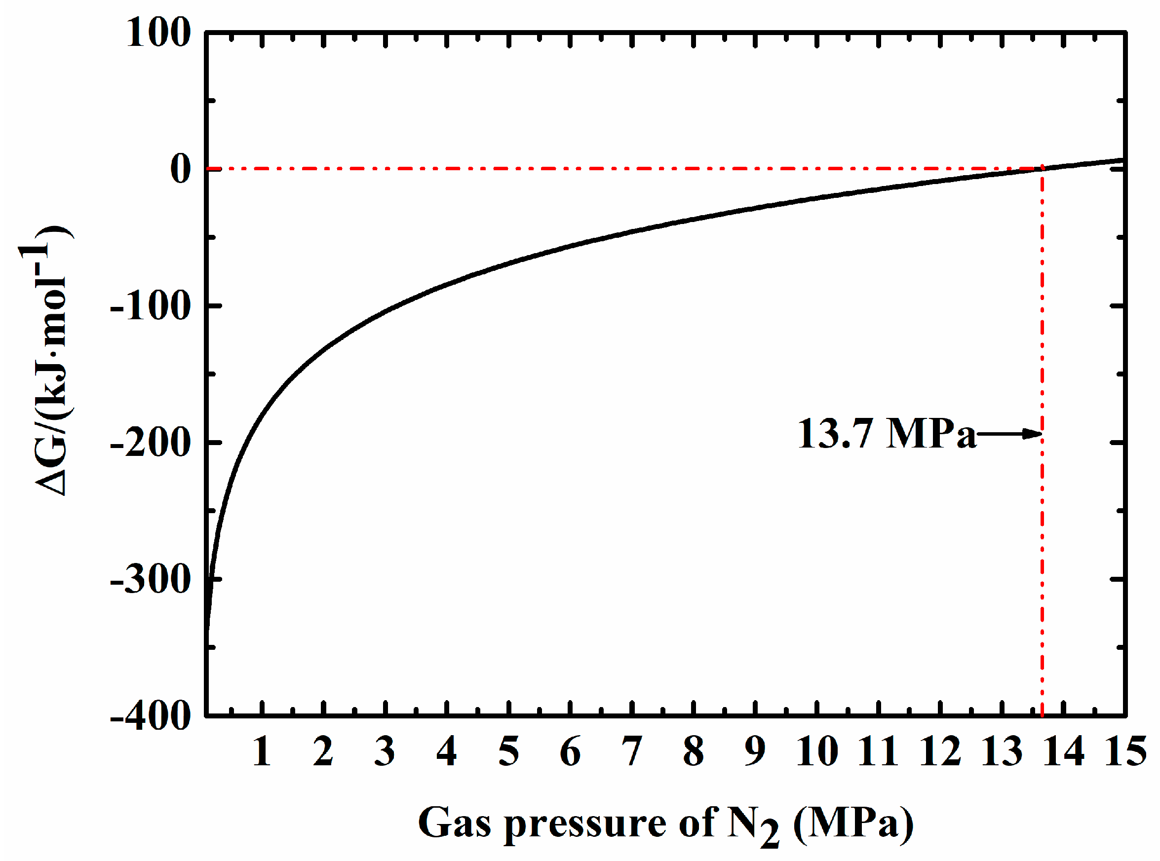
However, in our system, the sintering was conducted under a high N2 pressure (10 MPa). Furthermore, in the process of gas-pressure sintering, with an increasing temperature, the pores of the ceramic became closed pores so that the N2 that was produced through the above reaction could not be released, resulting in a local environment with an even higher N2 pressure which meant that the reaction could be suppressed, making Fe3Si stable to survive the sintering process. Thermodynamic analysis was done to calculate the Gibbs free energy of the reaction, and the results are present in Figure 3. It can be seen that with an increasing pressure of N2, the Gibbs free energy drops gradually. When N2 pressure was above 13.7 MPa, the Gibbs free energy was greater than 0 kJ·mol−1, indicating that the reaction could no longer continue. In our sintering condition, the external pressure of N2 was 10 MPa, therefore when the reaction occured and N2 was produced, the local pressure of N2 was much higher than 10 MPa, meaning the reaction could be suppressed or even stopped.
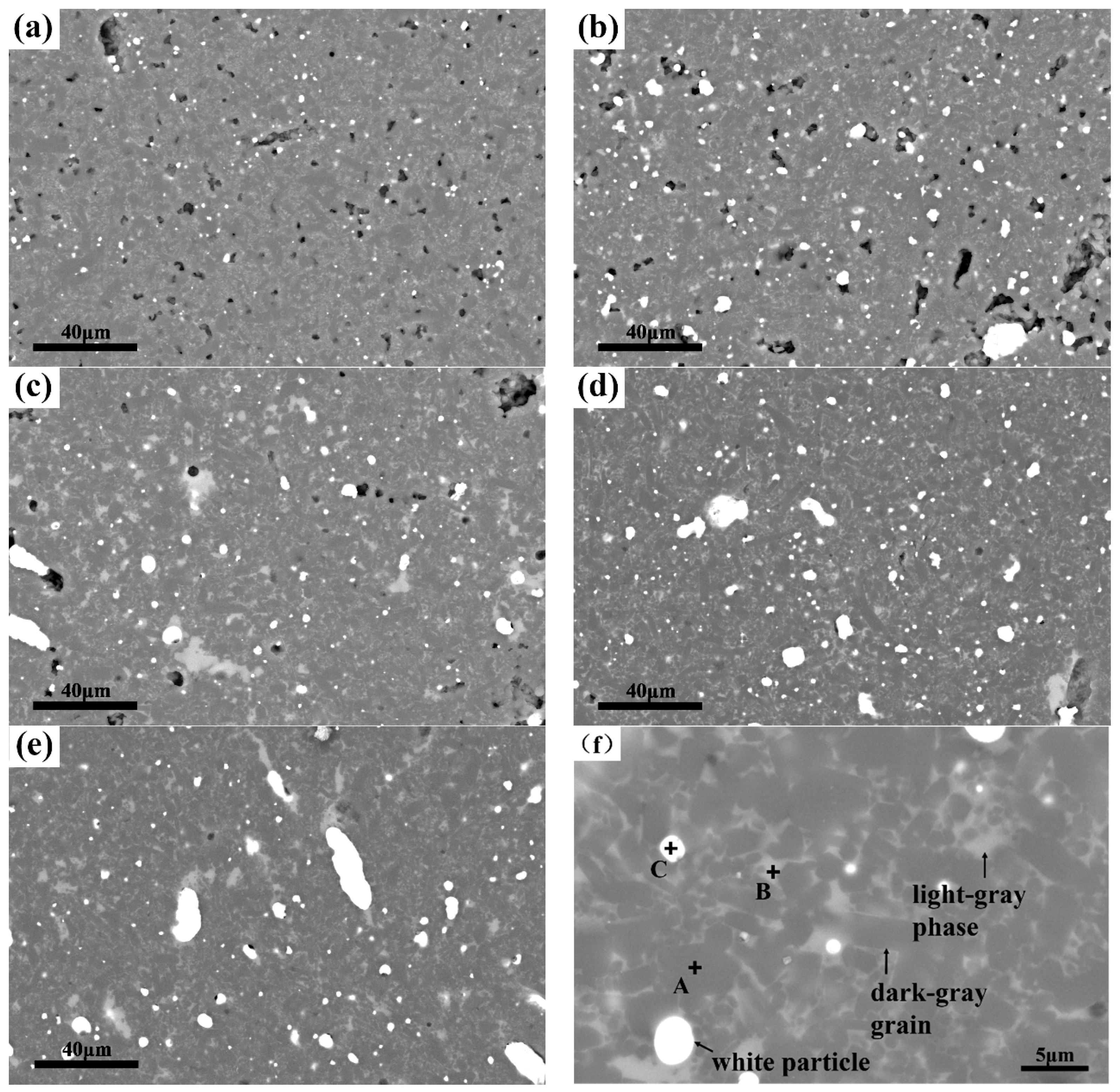
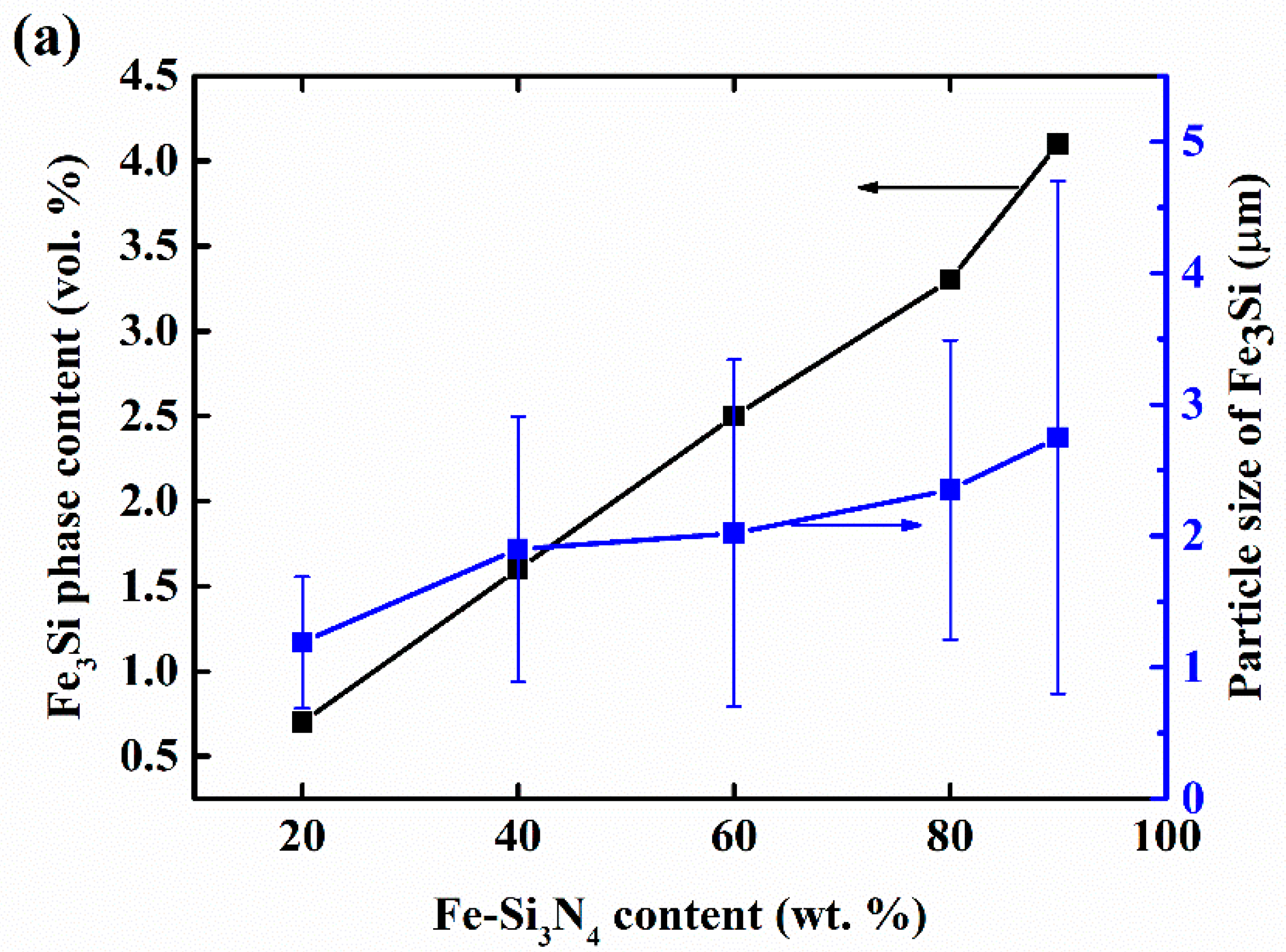
Figure 4 shows the BSE images and energy-dispersive X-ray spectroscopy (EDS) analysis of the composites. It can be seen from Figure 4a–f that all of the samples were mainly composed of three phases which are indicated by arrows in Figure 4f: the dark-gray columnar grains, the light-gray phases, and the white dispersive particles. EDS analysis (Table 3) confirmed that they are Si3N4, grain boundary phases, and Fe3Si, respectively. It can be clearly noted that, with the increase of Fe-Si3N4 content in the raw materials, the content of the Fe3Si phase in the composites arises. More importantly, the particle size of Fe3Si grows remarkably. In Figure 4a, the particle size of Fe3Si is smaller than 5 μm. However, in Figure 4e, Fe3Si particles that are bigger than 20 μm can be found. This phenomenon was confirmed by particle size measurements through image analysis (Figure 5). In Figure 5a, it can be found that the volume content rose in approximate linearity with the increase of Fe-Si3N4 content. The volume fraction of Fe3Si for FSN20, FSN40, FSN 60, FSN80, and FSN90 after sintering are 0.7, 1.6, 2.5, 3.3, and 4.1 vol. %. Assuming that Fe-Si3N4 contains 18 wt. % Fe3Si and the density of Fe3Si is 6.34 g/cm3 [37], the content of Fe3Si for each sample before sintering are calculated and the results (see Table 1) are 1.9, 3.9, 5.9, 8.1, and 9.2 vol. % respectively. So, we can estimate that about 60% of Fe3Si are sacrificed. There may be two reasons for the loss of Fe3Si. Firstly, Fe3Si dissolves into the grain boundary phase and EDS results showed that Fe exists in it. Secondly, since our method was based on the image analysis of BSE images, Fe3Si particles that were too small to recognize would have been neglected.
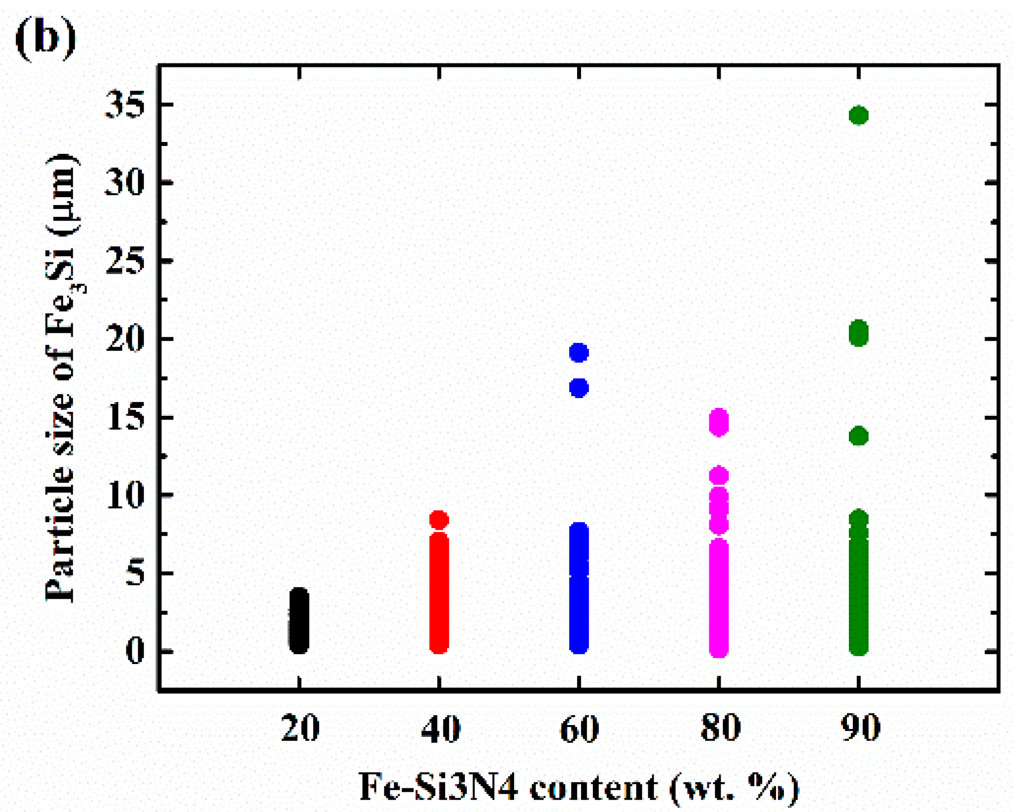
The average particle size of Fe3Si increased gradually from 1.19 μm to 2.75 μm. Figure 5b gives the particle size distribution of Fe3Si, from which it can be discovered that with the increase of Fe-Si3N4, although the average particle size of Fe3Si rose mildly, the abnormal growth of the particles occurred, and the number of big Fe3Si particles grew rapidly. In samples of FSN80 and FSN90, although the average size of Fe3Si remains relatively small, many Fe3Si particles that were bigger than 10 μm can be found frequently, indicating that with the increase of Fe-Si3N4 content in the starting powder, the degree of microstructure inhomogeneity would rise.
The difference in particle sizes and their distributions of Fe3Si in different samples can be explained by the flow of liquid Fe3Si in porous Si3N4 during the sintering process. Since the melting point of Fe3Si is about 1280 °C [38], at sintering temperature, the Fe3Si is in liquid state and can flow easily. When the content of Fe-Si3N4 was low and the Si3N4 content was high, the frameworks that were formed by the Si3N4 particles were relatively dense. Hence, the melting Fe3Si droplets were separated from each other and existed discretely. With the increase of the content of Fe-Si3N4 and the decrease of the content of Si3N4, the Si3N4 frameworks were weakened, and when the porosity of Si3N4 and the content of Fe3Si reached a critical point, percolation occurred and Fe3Si droplets joined each other and flowed to form bigger droplets and solidified into solid particles upon cooling.
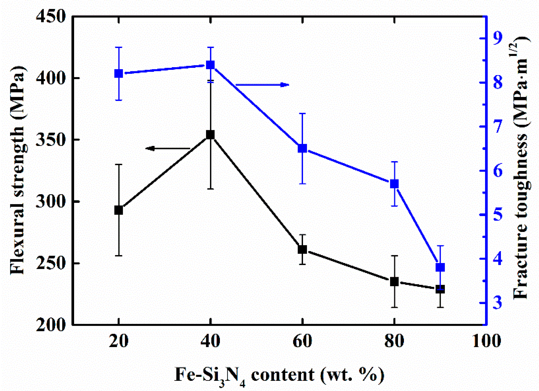
The mechanical properties of the Si3N4-Fe3Si composites are presented in Table 2 and Figure 6. From Table 2, we can see that the Vickers hardness of the samples decreased with the increase of Fe3Si content, which is as expected because the hardness of Fe3Si is much lower than that of Si3N4. Figure 6 shows the dependence of the flexural strength and fracture toughness of the Si3N4-Fe3Si composites on the content of Fe-Si3N4 in starting powders. It can be seen that the flexural strength and fracture toughness of FSN20 are 293 MPa and 7.9 MPa·m1/2, respectively. The highest flexural strength and fracture toughness were obtained (354 MPa and 8.4 MPa·m1/2) when the content of Fe-Si3N4 increased to 40 wt. %. However, a further increase in Fe-Si3N4 resulted in a gradual degradation of the mechanical properties of the composites. The above results showed that by carefully adjusting the composition of the raw materials, a Si3N4-Fe3Si composite with improved mechanical properties can be obtained. Dense monolithic Si3N4 ceramics that are fabricated using Si3N4 powder with high purity typically show good mechanical properties (three point bending strength of 400~900 MPa and fracture toughness of 3.4~8.2 MPa·m1/2 [39]). Our results show that by replacing 40 wt. % Si3N4 powder with the cost-effective Fe-Si3N4 powder, composites can obtain mechanical properties—especially fracture toughness that is at the same level with dense monolithic Si3N4 ceramics.
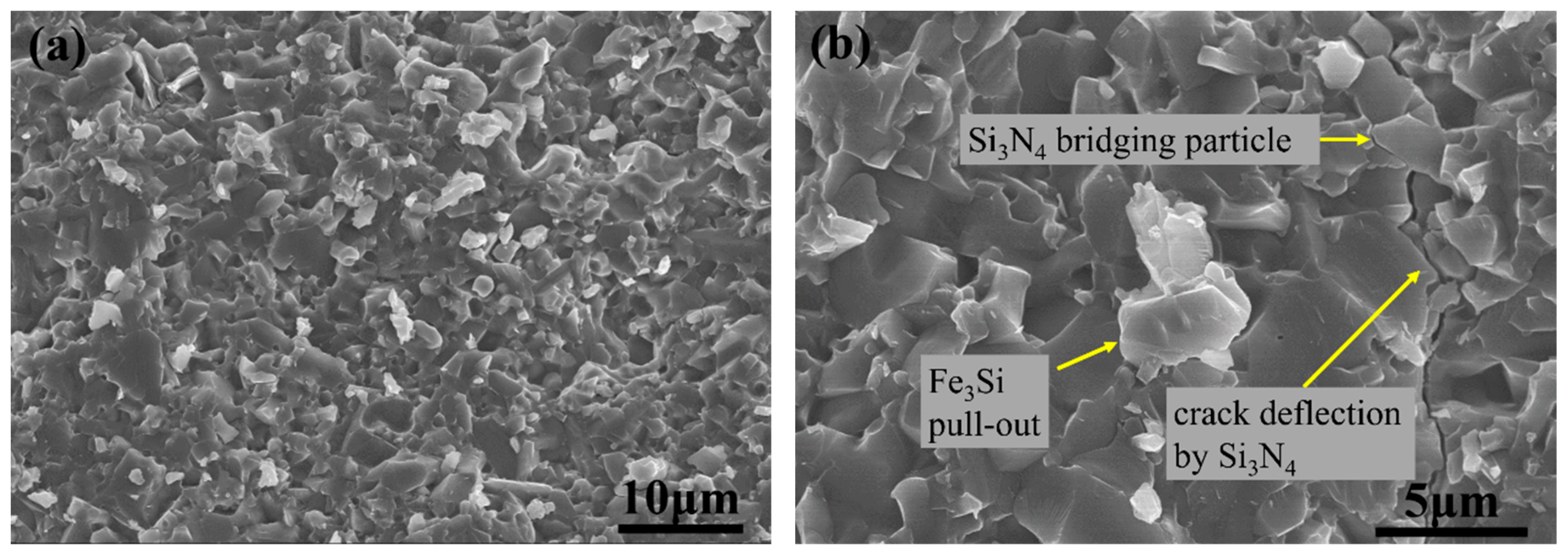
In order to research the microstructure—the mechanical properties’ relationship of the composites, fracture surface and crack/microstructure interactions were observed. Figure 7 shows the fracture surface of FSN40. In Figure 7a, it can be seen that fracture modes of the composites were in co-action by transgranular and intergranular fracture. Since Si3N4 has its well-known characteristic of self-reinforcement, two kinds of typical toughening mechanisms of crack bridging and crack deflection by Si3N4 can be found in Figure 7b, which resulted from the elongated Si3N4 crystals that were bounded by the weak interface [40]. Apart from the toughening mechanisms that were caused by Si3N4, pull out of Fe3Si particle can also be found in Figure 7b, indicating that Fe3Si also plays a part in toughening the composites.
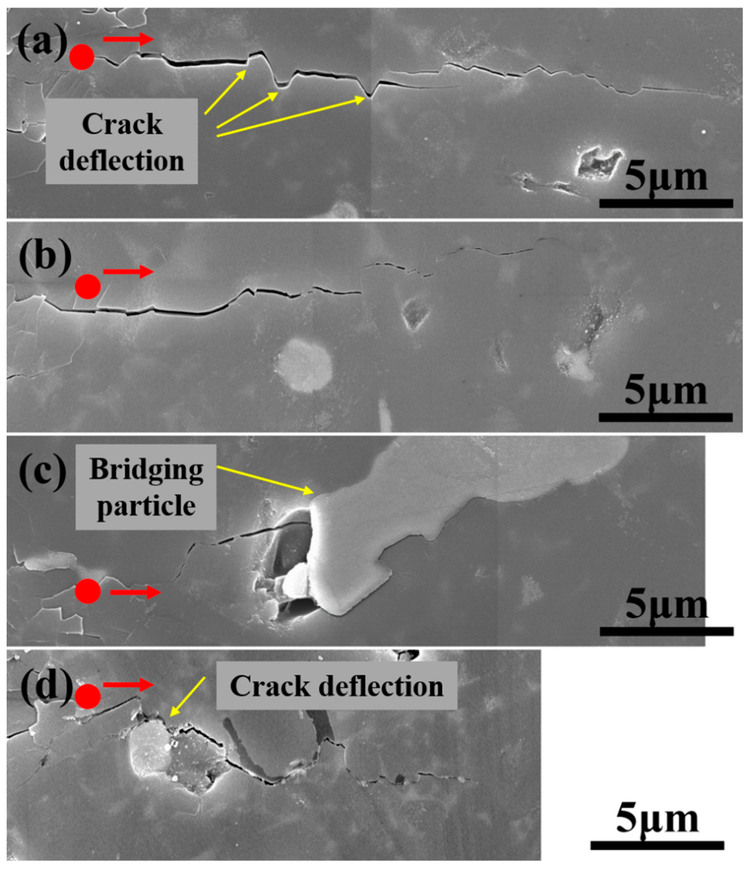
The toughening effect of Fe3Si was further studied by Vickers indentation (Figure 8). Four typical cracks (Figure 8a–d) in sample FSN60 were selected for detailed analysis. The propagation paths of the cracks shown in Figure 8a,b were free of Fe3Si particles, and although crack deflection by Si3N4 crystals can be seen (Figure 8a), the crack lengths was relatively long (24.0 μm and 18.9 μm, respectively). In Figure 8c,d, where the cracks interacted with Fe3Si in the form of interface debonding, particle bridging, and crack deflection, the crack length was smaller (15.3 μm and 14.7 μm, respectively), which indicates an improved toughness. Since Fe3Si has better plasticity than the brittle Si3N4, when the crack propagated to the vicinity of the Fe3Si particle, the stress concentration around the crack tip can be somewhat reduced, thus the tendency to the ripping of the material was inhibited. The CTE of Fe3Si (14.4 × 10⁻⁶ K−1 [41]) was much bigger than that of Si3N4 (2.9 × 10⁻⁶ K−1 [39]), so the interface between Fe3Si and Si3N4 was under tensile stress at room temperature, resulting in a weak interfacial bonding strength. When under stress, the weak interface between Fe3Si and the surrounding phase debonded (Figure 8c,d). This led to a tortuous crack path (Figure 8d) or particle bridging (Figure 8d).
With the above-revealed toughening mechanism of Fe3Si, the dependence of the flexural strength and fracture toughness of the Si3N4-Fe3Si composites on the content of Fe-Si3N4 in starting powders can be explained. The inherent brittleness of ceramics is determined by its poor plasticity, so that when under stress, little energy can be consumed by the plastic flow. In order to improve the fracture toughness of ceramics, other energy dissipation mechanisms like crack deflection, bridging, or particle pull-out are often utilized in ceramic composites. Compared with the sample of FSN20, FSN40 contains more Fe3Si particles and the particle size of Fe3Si in it remains small (Figure 5). Large amounts of fine dispersed Fe3Si particles improved the strength and toughness of FSN40. When the content of Fe-Si3N4 in starting powders was more than 60 wt. %, despite the fact that the phase content of Fe3Si increased, the Fe3Si particles suffered severe growth, and large particles that were bigger than 15 μm emerged (Figure 5b). Large Fe3Si particles result in a non-uniform microstructure and may serve as crack origins when the samples are loaded, so the mechanical properties of FSN60, FSN80, and FSN90 are damaged. Narciso [42,43] studied the coefficient of the thermal expansion (CTE) properties of several metal-ceramic composites, and it was found that metals usually have CTE one magnitude higher than that of ceramics. In our study, the interface of Fe3Si and Si3N4 are under residue tensile stress due to the mismatch of CTEs. The residue tensile stress may result in cracks and voids between Fe3Si and Si3N4, which can act as a crack origin when under stress, and this may be one reason for the low mechanical properties of the composite with a high Fe3Si content.
4. Conclusions
In this study, Si3N4-Fe3Si composites with a different content of the Fe3Si phase were fabricated using starting powders of different compositions. The microstructure and mechanical properties of the composites were investigated by various methods. Special attention was placed on the particle size distribution of Fe3Si and their effect on the mechanical properties of the composites. The main conclusions can be summarized as follows.
The sintered composites were mainly composed of Si3N4, Fe3Si, and the grain boundary phase. With the increase of Fe-Si3N4 powder from 20 wt. % to 90 wt. % in the starting powder, the Fe3Si phase content increased from 0.7 vol. % to 4.1 vol. %, and the particle size increased from 1.2 μm to 2.8 μm. When more than 60 wt. % Fe-Si3N4 was added to the starting powders, the abnormal growth of Fe3Si particles occurred and particles bigger than 15 μm were commonly seen, leading to non-uniform microstructures and poor mechanical properties. The dispersive Fe3Si particles had a toughening effect on the composites through mechanisms such as particle pull-out, interface debonding, crack deflection, and particle bridging. Owing to the uniform microstructure and Fe3Si toughening, FSN40 showed the highest flexural strength and fracture toughness of 354 MPa and 8.4 MPa·m1/2, respectively, indicating great potential as thermal structural materials.
Author Contributions
Conceptualization, J.G. and L.C.; Methodology, J.G. and L.C.; Formal Analysis, J.G. and M.L.; Investigation, J.G. and M.L.; Writing-Original Draft Preparation, J.G.; Writing-Review & Editing, L.C. and M.L.
Funding
This research was funded by the Chinese National Foundation for Natural Sciences (Grant nos. 51632007) and the National Key R&D Program of China (Grant nos. 2017YFB1103500).
Conflicts of Interest
The authors declare no conflict of interest.
References
- Riley, F.L. Silicon nitride and related materials. J. Am. Ceram. Soc. 2000, 83, 245–265. [Google Scholar] [CrossRef]
- Klemm, H. Silicon Nitride for High-Temperature Applications. J. Am. Ceram. Soc. 2010, 93, 1501–1522. [Google Scholar] [CrossRef]
- Shen, Z.; Zhao, Z.; Peng, H.; Nygren, M. Formation of tough interlocking microstructures in silicon nitride ceramics by dynamic ripening. Nature 2002, 417, 266–269. [Google Scholar] [CrossRef] [PubMed]
- Petzow, G.; Herrmann, M. Silicon nitride ceramics. In High Performance Non-Oxide Ceramics II; Springer: Berlin/Heidelberg, Germany, 2002; pp. 47–167. [Google Scholar]
- Kometani, K.; Iizuka, K.; Kaga, T. Behavior of Ferro-Si3N4 in Taphole Mud of Blast Furnace. Refractories 1998, 50, 326–330. [Google Scholar]
- Ziatdinov, M.K.; Shatokhin, I. Using ferrosilicon nitride of nitro-fesil grade in gate and spout components. Refract. Ind. Ceram. 2008, 49, 383–387. [Google Scholar] [CrossRef]
- Mitomo, M. Effect of Fe and Al additions on nitridation of silicon. J. Mater. Sci. 1977, 12, 273–276. [Google Scholar] [CrossRef]
- Vlasova, M.; Lavrenko, V.; Dyubova, L.Y.; Gonzalez-Rodriguez, J.; Kakasey, M. Nitriding of ferrosilicon powders. J. Mater. Synth. Process. 2001, 9, 111–117. [Google Scholar] [CrossRef]
- Wang, Y.; Cheng, L.; Guan, J.; Zhang, L. Effect of dilution and additive on direct nitridation of ferrosilicon. J. Eur. Ceram. Soc. 2014, 34, 1115–1122. [Google Scholar] [CrossRef]
- Chukhlomina, L. Fundamental aspects of silicon nitride synthesis by combustion of an iron-silicon alloy in nitrogen. Russ. J. Appl. Chem. 2007, 80, 1793–1797. [Google Scholar] [CrossRef]
- Chukhlomina, L.; Maksimov, Y.M.; Kitler, V.; Vitushkina, O. Mechanism and features of nitriding of ferrosilicon in the combustion regime. Combust. Explos. Shock Waves 2006, 42, 309–316. [Google Scholar] [CrossRef]
- Chukhlomina, L.; Maksimov, Y.M. Combustion of the Fe-Si alloy in nitrogen gas. Int. J. Self-Propagating High-Temp. Synth. 2007, 16, 18–22. [Google Scholar] [CrossRef]
- Chukhlomina, L. Chemically and thermally conjugate synthesis of silicon nitride based compositions using ferrosilicon. Glass Ceram. 2009, 66, 288–292. [Google Scholar] [CrossRef]
- Pavarajarn, V.; Kimura, S. Catalytic effects of metals on direct nitridation of silicon. J. Am. Ceram. Soc. 2001, 84, 1669–1674. [Google Scholar] [CrossRef]
- Lin, S.S. Comparative studies of metal additives on the nitridation of silicon. J. Am. Ceram. Soc. 1977, 60, 78–81. [Google Scholar] [CrossRef]
- Chen, J.H.; Wen, S.; Liu, X.G. Formation mechanism of FexSi particles in ferro-silicon nitride prepared via flashing combustion. J. Univ. Sci. Technol. Beijing 2009, 31, 597–601. [Google Scholar]
- Chukhlomina, L.; Maksimov, Y.M.; Vitushkina, O.; Golobokov, N.; Vereshchagin, V.I. Phase composition and morphology of products of combustion of ferrosilicon in nitrogen. Glass Ceram. 2007, 64, 63–65. [Google Scholar] [CrossRef]
- Zhang, Y.; Peng, D.Y.; Wen, H.J. Sintering process of special ceramics Fe-Si3N4 bonded SiC. J. Iron Steel Res. 2002, 14, 25–28. [Google Scholar]
- Li, Y.; Zhu, X.Y.; Zhai, Y.W.; Wang, J.P.; Xue, W.D.; Chen, J.H.; Sun, J.L. Study on High Performance Fe3Si-Si3N4-SiC Composite Preparation and its Application in Blast Furnace. Adv. Mater. Res. 2011, 194–196, 1547–1553. [Google Scholar] [CrossRef]
- Vitushkina, O.; Chukhlomina, L.; Vereshchagin, V.I. Preparation of Si3N4–ZrO2 ceramic composites by self-propagating high-temperature synthesis. Refract. Ind. Ceram. 2012, 52, 402–404. [Google Scholar] [CrossRef]
- Daniel, B.; Murthy, V.; Murty, G. Metal-ceramic composites via in-situ methods. J. Mater. Process. Technol. 1997, 68, 132–155. [Google Scholar] [CrossRef]
- Burkes, D.E.; Gottoli, G.; Moore, J.J.; Yi, H.C. Combustion synthesis and mechanical properties of dense NiTi-TiC intermetallic-ceramic composites. Metall. Mater. Trans. A 2006, 37, 235–242. [Google Scholar] [CrossRef]
- Schneibel, J.; Carmichael, C.; Specht, E.; Subramanian, R. Liquid-phase sintered iron aluminide-ceramic composites. Intermetallics 1997, 5, 61–67. [Google Scholar] [CrossRef]
- Klassen, T.; Günther, R.; Dickau, B.; Gärtner, F.; Bartels, A.; Bormann, R.; Mecking, H. Processing and properties of intermetallic/ceramic composites with interpenetrating microstructure. J. Am. Ceram. Soc. 1998, 81, 2504–2506. [Google Scholar] [CrossRef]
- Sglavo, V.M.; Marino, F.; Zhang, B.R.; Gialanella, S. Ni3Al intermetallic compound as second phase in Al2O3 ceramic composites. Mater. Sci. Eng. 1997, 239–240, 665–671. [Google Scholar] [CrossRef]
- Chen, W.-W.; Cheng, Y.-B.; Tuan, W.-H. Preparation of sialon–transition metal silicide composites. J. Eur. Ceram. Soc. 2006, 26, 193–199. [Google Scholar] [CrossRef]
- Gong, H.; Yin, Y.; Wang, X.; Liu, Y. Fabrication and microstructure of in situ toughened Al2O3/Fe3Al. Mater. Res. Bull. 2004, 39, 513–521. [Google Scholar] [CrossRef]
- Wang, L.; Qi, Q.; Wu, H.; Zhang, H.; Yin, J.; Yang, Y.; Liu, X.; Huang, Z. Stress distribution around Fe5Si3 and its effect on interface status and mechanical properties of Si3N4 ceramics. J. Am. Ceram. Soc. 2018, 101, 856–864. [Google Scholar] [CrossRef]
- Koch, C.C.; Liu, C.T.; Stoloff, N.S.; Wanner, A. High-Temperature Ordered Intermetallic Alloys; Materials Research Society: Warrendale, PA, USA, 1989. [Google Scholar]
- Miglio, L.; D’Heurle, F. Silicides: Fundamentals and Applications. Mater. Trans. 1923, 43, 1023–1029. [Google Scholar]
- Becerro, A.I.; Escudero, A. Phase Transitions in Lu-Doped Y2Si2O7 at High Temperatures. Chem. Mater. 2005, 17, 112–117. [Google Scholar] [CrossRef]
- Bouarroudj, A.; Goursat, P.; Besson, J.L. Oxidation resistance and creep behaviour of a silicon nitride ceramic densified with Y2O3. J. Mater. Sci. 1985, 20, 1150–1159. [Google Scholar] [CrossRef]
- Cinibulk, M.K.; Thomas, G.; Johnson, S.M. Strength and Creep Behavior of Rare-Earth Disilicate–Silicon Nitride Ceramics. J. Am. Ceram. Soc. 1992, 75, 2050–2055. [Google Scholar] [CrossRef]
- Eustathopoulos, N.; Nicholas, M.G.; Drevet, B. (Eds.) Wettability at High Temperatures; Elsevier: Amsterdam, The Netherlands, 1999. [Google Scholar]
- Narciso-Romero, F.J.; Rodriguez-Reinoso, F. Synthesis of SiC from rice husks catalysed by iron, cobalt or nickel. J. Mater. Sci. 1996, 31, 779–784. [Google Scholar] [CrossRef]
- Shimoo, T.; Okamura, K.; Yamasaki, T. Reaction between Si3N4 and Fe-Ni alloy. J. Mater. Sci. 1999, 34, 5525–5532. [Google Scholar] [CrossRef]
- Novgorodova, M.I.; Yusupov, R.G.; Dmitrieva, M.T.; Tsepin, A.I.; Sivtsov, A.V.; Gorshkov, A.I.; Korovushkin, V.V.; Yakubovskaya, N.Y. First occurrence of suessite on the Earth. Int. Geol. Rev. 1984, 26, 98–101. [Google Scholar] [CrossRef]
- Dokken, R.N. A resistance-measurement study of ordering in iron-silicon alloys FeSi-and Fe3Si-type superstructures. Trans. AIME 1965, 233, 1187. [Google Scholar]
- Ziegler, G.; Heinrich, J.; Wötting, G. Relationships between processing, microstructure and properties of dense and reaction-bonded silicon nitride. J. Mater. Sci. 1987, 22, 3041–3086. [Google Scholar] [CrossRef]
- Becher, P.F.; Painter, G.S.; Sun, E.Y.; Hsueh, C.H.; Lance, M.J. The importance of amorphous intergranular films in self-reinforced Si3N4 ceramics. Acta. Mater. 2000, 48, 4493–4499. [Google Scholar] [CrossRef]
- Neshpor, V.S.; Reznichenko, M. Investigating the thermal expansion of some silicides. Refractories 1963, 4, 145–148. [Google Scholar] [CrossRef]
- Mario, C.; Xiang, C.; Narciso, J.; Gupta, N. Reactive melt infiltration as synthesis route for enhanced SiC/CoSi2 composite materials for advanced armor systems. Ceram. Int. 2018, 44, 13182–13190. [Google Scholar]
- Arpon, R.; Molina, J.M.; Saravanan, R.A.; García-Cordovilla, C.; Louis, E.; Narciso, J. Thermal expansion behaviour of aluminium/SiC composites with bimodal particle distributions. Acta Mater. 2003, 51, 3145–3156. [Google Scholar] [CrossRef]
Figure 1.
Size distribution of the starting powders.
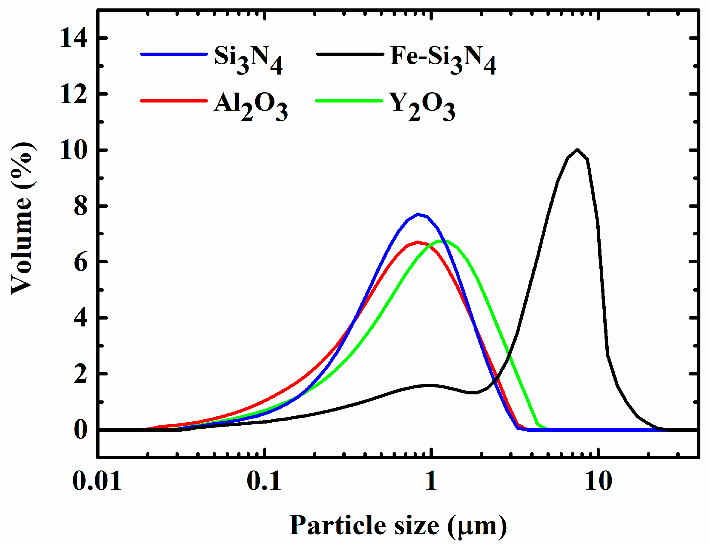
Figure 2.
X-ray diffraction patterns of FSN20, FSN40, FSN60, FSN80, and FSN90. Peak positions of α-Si3N4 (ICDD PDF Card No. 41-0360) are denoted as the vertical lines at the bottom of the coordinate system.
Figure 2.
X-ray diffraction patterns of FSN20, FSN40, FSN60, FSN80, and FSN90. Peak positions of α-Si3N4 (ICDD PDF Card No. 41-0360) are denoted as the vertical lines at the bottom of the coordinate system.
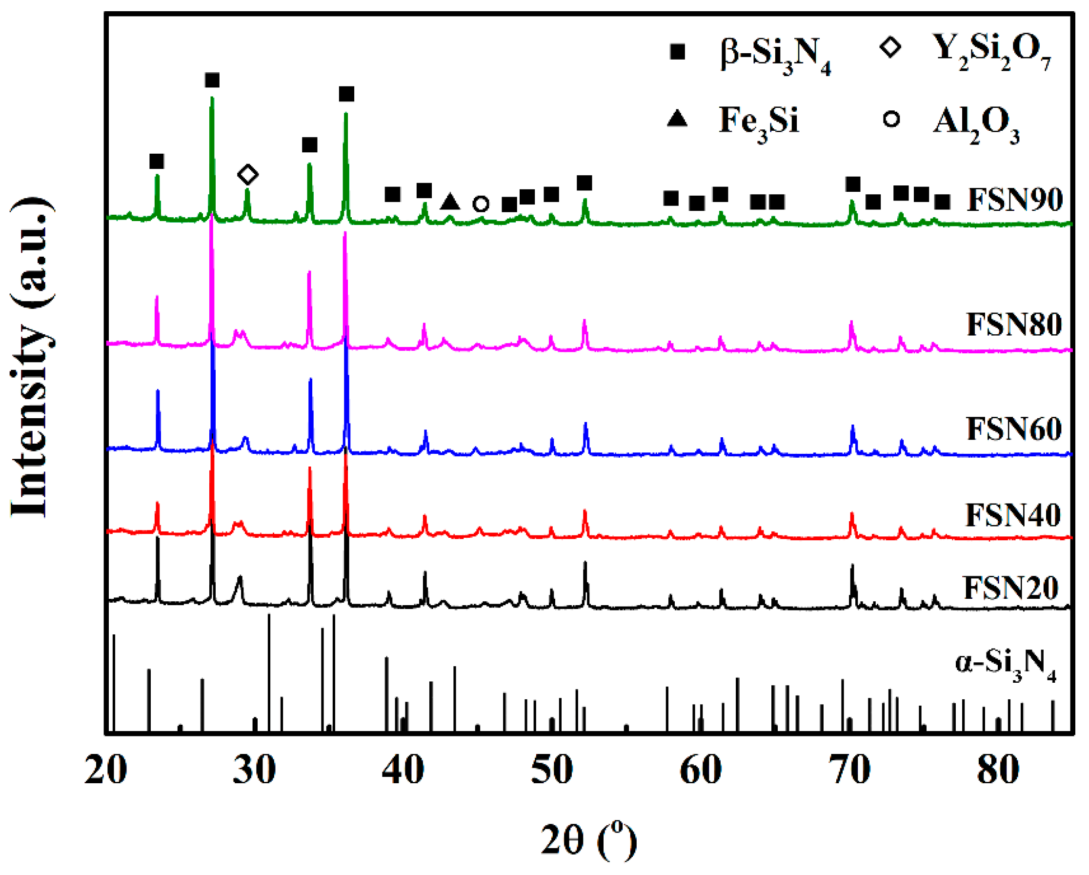
Figure 3.
Gibbs free energy of reaction (4) at 1800 °C under different N2 pressures.

Figure 4.
Back scattered electron (BSE) morphologies and (energy-dispersive X-ray spectroscopy) EDS analysis of the Si3N4-Fe3Si composites. (a–e) BSE morphologies of FSN20—FSN90. (f) High magnification of the BSE images and EDS analysis of FSN60.
Figure 4.
Back scattered electron (BSE) morphologies and (energy-dispersive X-ray spectroscopy) EDS analysis of the Si3N4-Fe3Si composites. (a–e) BSE morphologies of FSN20—FSN90. (f) High magnification of the BSE images and EDS analysis of FSN60.

Figure 5.
(a) Phase content, average particle size, and (b) particle size distribution of Fe3Si in the Si3N4-Fe3Si composites prepared with starting powders containing a different amount of Fe-Si3N4. In Figure 5b, 250 data of each particle size of each sample (represented by round dots with different colors) were selected randomly to illustrate the particle size distribution.


Figure 6.
Flexural strength and fracture toughness of Si3N4-Fe3Si composites (FSN20, FSN40, FSN60, FSN80, and FSN90) prepared with starting powders containing different contents of Fe-Si3N4.
Figure 6.
Flexural strength and fracture toughness of Si3N4-Fe3Si composites (FSN20, FSN40, FSN60, FSN80, and FSN90) prepared with starting powders containing different contents of Fe-Si3N4.

Figure 7.
Fracture surface of FSN40. (a) Low magnification. (b) High magnification.

Figure 8.
Crack/microstructure interactions in FSN60. Four typical cracks (a–d) were selected for detailed analysis. Red points stand for the diagonal apexes of the indentations. Red arrows stand for the propagation direction of the cracks.
Figure 8.
Crack/microstructure interactions in FSN60. Four typical cracks (a–d) were selected for detailed analysis. Red points stand for the diagonal apexes of the indentations. Red arrows stand for the propagation direction of the cracks.


Table 1.
Compositions of the starting powders used to prepare Si3N4-Fe3Si composites.
| Samples | Fe-Si3N4 | Si3N4 | Y2O3 | Al2O3 | Fe3Si in Starting Materials |
|---|---|---|---|---|---|
| (wt. %) | (wt. %) | (wt. %) | (wt. %) | (vol. %) | |
| FSN20 | 20 | 70 | 5 | 5 | 1.9 |
| FSN40 | 40 | 50 | 5 | 5 | 3.9 |
| FSN60 | 60 | 30 | 5 | 5 | 5.9 |
| FSN80 | 80 | 10 | 5 | 5 | 8.1 |
| FSN90 | 90 | 0 | 5 | 5 | 9.2 |
Table 2.
Density, open porosity, and mechanical property of the Si3N4-Fe3Si composites.
| Samples | Density (g/cm3) | Open Porosity (%) | Vickers Hardness (GPa) | Flexural Strength (MPa) | Fracture Toughness (MPa·m1/2) | |
|---|---|---|---|---|---|---|
| SENB | Indentation | |||||
| FSN-20 | 3.20 | 0.67 | 11.21 | 293 ± 37 | 8.2 ± 0.6 | 9.6 ± 0.9 |
| FSN-40 | 3.28 | 0.46 | 9.91 | 354 ± 44 | 8.4 ± 0.4 | 10.1 ± 0.8 |
| FSN-60 | 3.28 | 0.65 | 9.43 | 261 ± 12 | 6.5 ± 0.8 | 8.1 ± 0.8 |
| FSN-80 | 3.29 | 2.06 | 9.19 | 235 ± 21 | 5.7 ± 0.5 | 7.0 ± 0.5 |
| FSN-90 | 3.37 | 1.17 | 8.79 | 229 ± 15 | 3.8 ± 0.5 | 4.6 ± 0.7 |
Table 3.
EDS analysis of spots in Figure 4f.
Table 3.
EDS analysis of spots in Figure 4f.
| Element | Spot A | Spot B | Spot C | |
|---|---|---|---|---|
| Atom ratio (%) | Si | 55.4 | 22.5 | 23.0 |
| N | 44.6 | 18.0 | 0 | |
| Y | - | 8.1 | 0 | |
| Al | - | 11.0 | 0 | |
| O | - | 38.9 | 0 | |
| Fe | - | 1.5 | 77.0 | |
© 2018 by the authors. Licensee MDPI, Basel, Switzerland. This article is an open access article distributed under the terms and conditions of the Creative Commons Attribution (CC BY) license (http://creativecommons.org/licenses/by/4.0/).
Share and Cite
MDPI and ACS Style
Guan, J.; Cheng, L.; Li, M. Microstructure and Mechanical Properties of Si3N4-Fe3Si Composites Prepared by Gas-Pressure Sintering. Materials 2018, 11, 1206. https://doi.org/10.3390/ma11071206
AMA Style
Guan J, Cheng L, Li M. Microstructure and Mechanical Properties of Si3N4-Fe3Si Composites Prepared by Gas-Pressure Sintering. Materials. 2018; 11(7):1206. https://doi.org/10.3390/ma11071206
Chicago/Turabian StyleGuan, Jiasuo, Laifei Cheng, and Mingxing Li. 2018. "Microstructure and Mechanical Properties of Si3N4-Fe3Si Composites Prepared by Gas-Pressure Sintering" Materials 11, no. 7: 1206. https://doi.org/10.3390/ma11071206
Note that from the first issue of 2016, this journal uses article numbers instead of page numbers. See further details here.