Ballistic Performance of Nanostructured Metals Toughened by Elliptical Coarse-Grained Inclusions: A Finite Element Study with Failure Analysis


Abstract
:1. Introduction
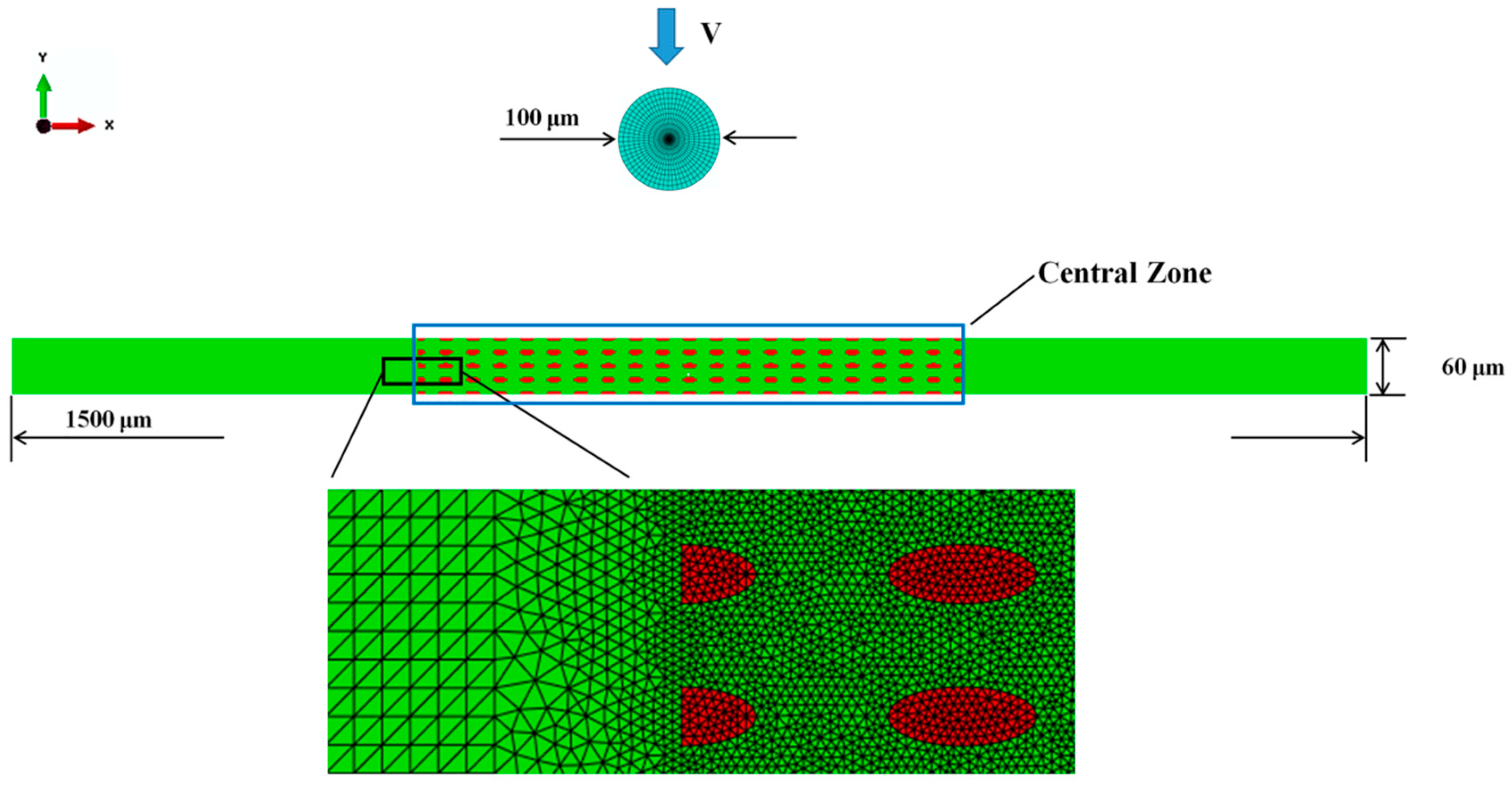
2. Modelling Method
2.1. Idealized Microstructures
2.2. Constitutive Relation and Failure Criterion of the NG Phase
3. Results and Discussion
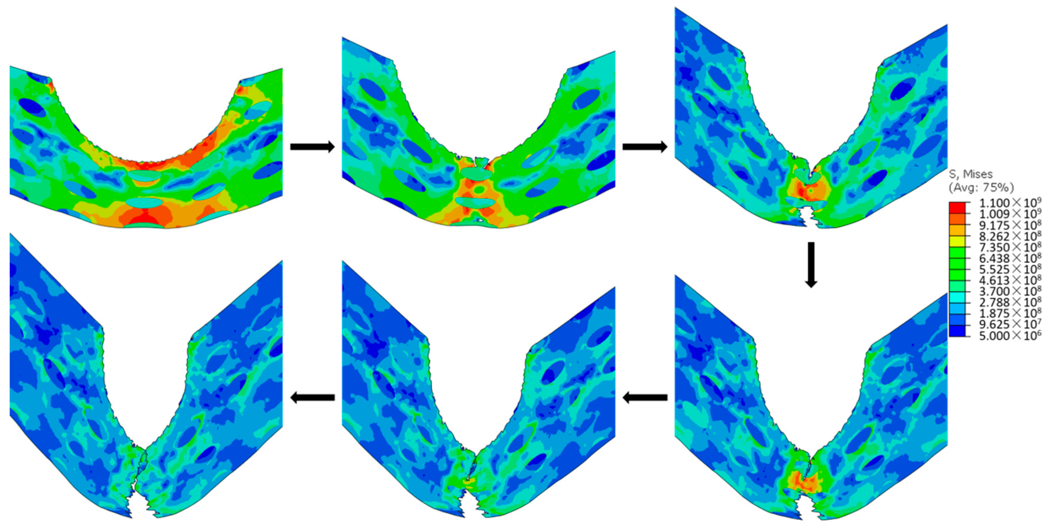
3.1. General Impact Process
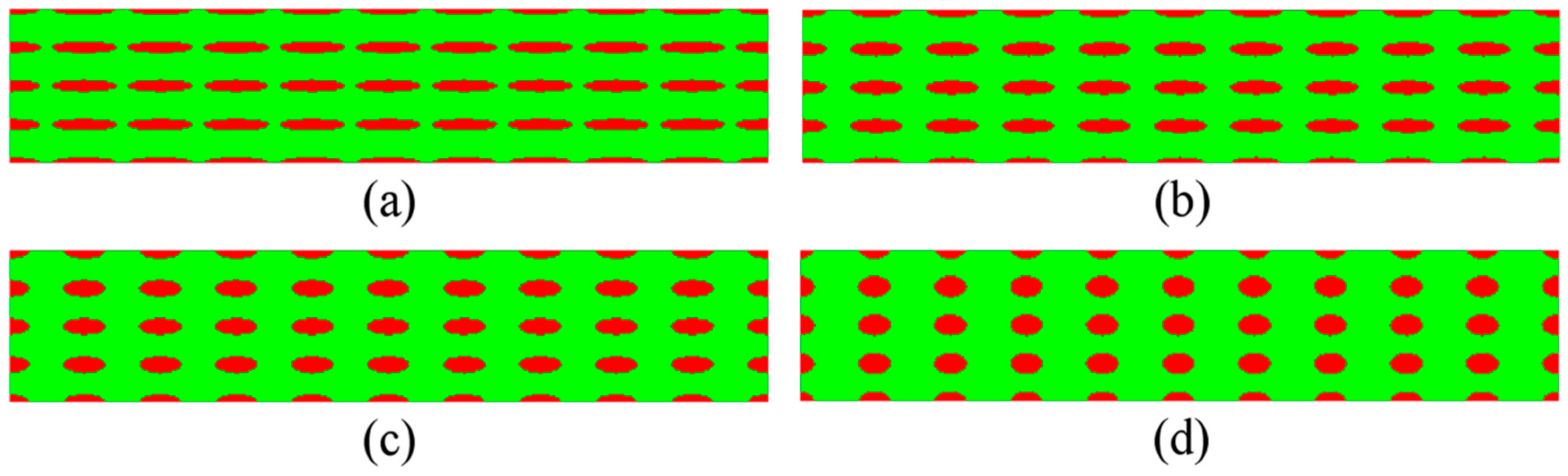
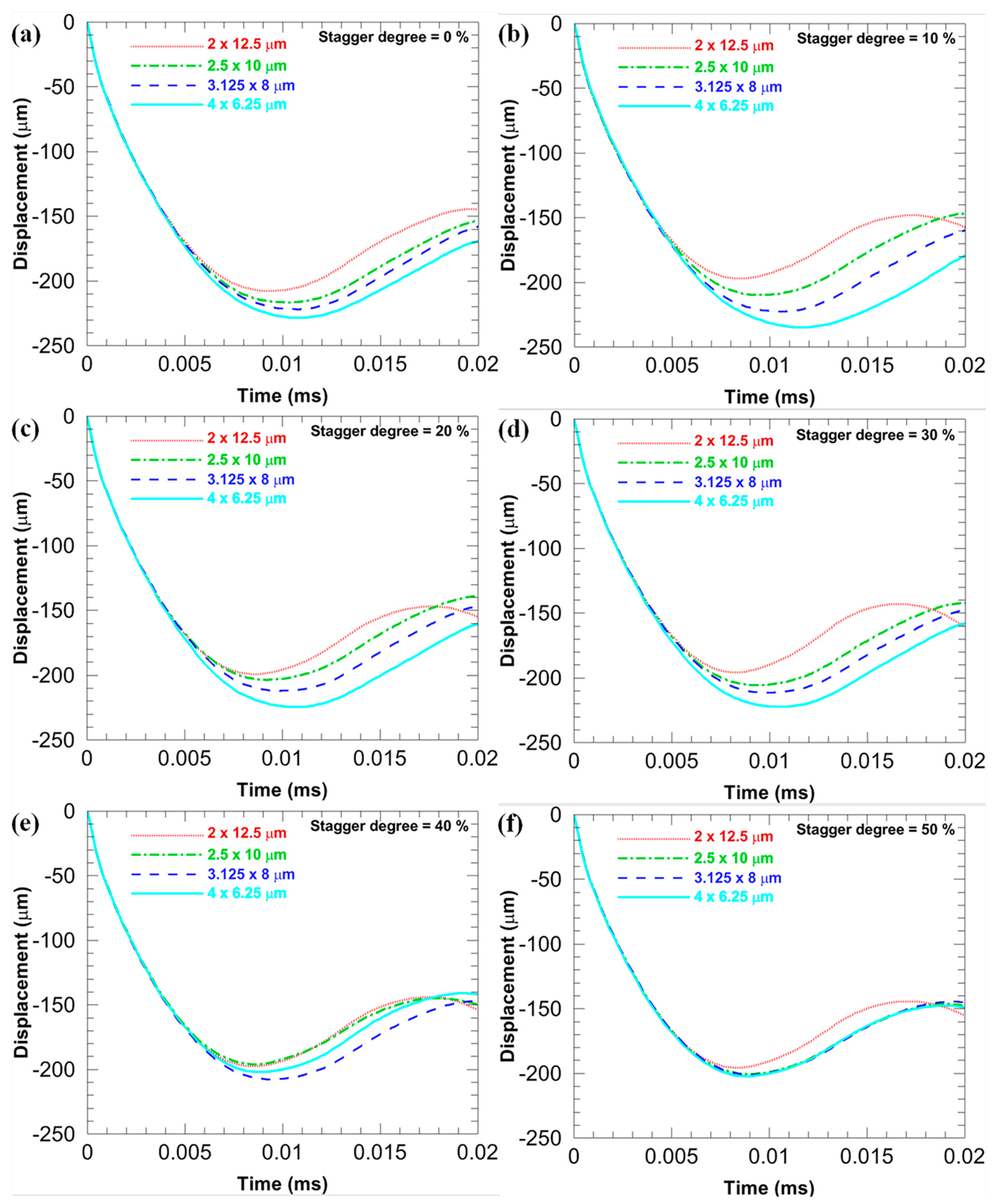
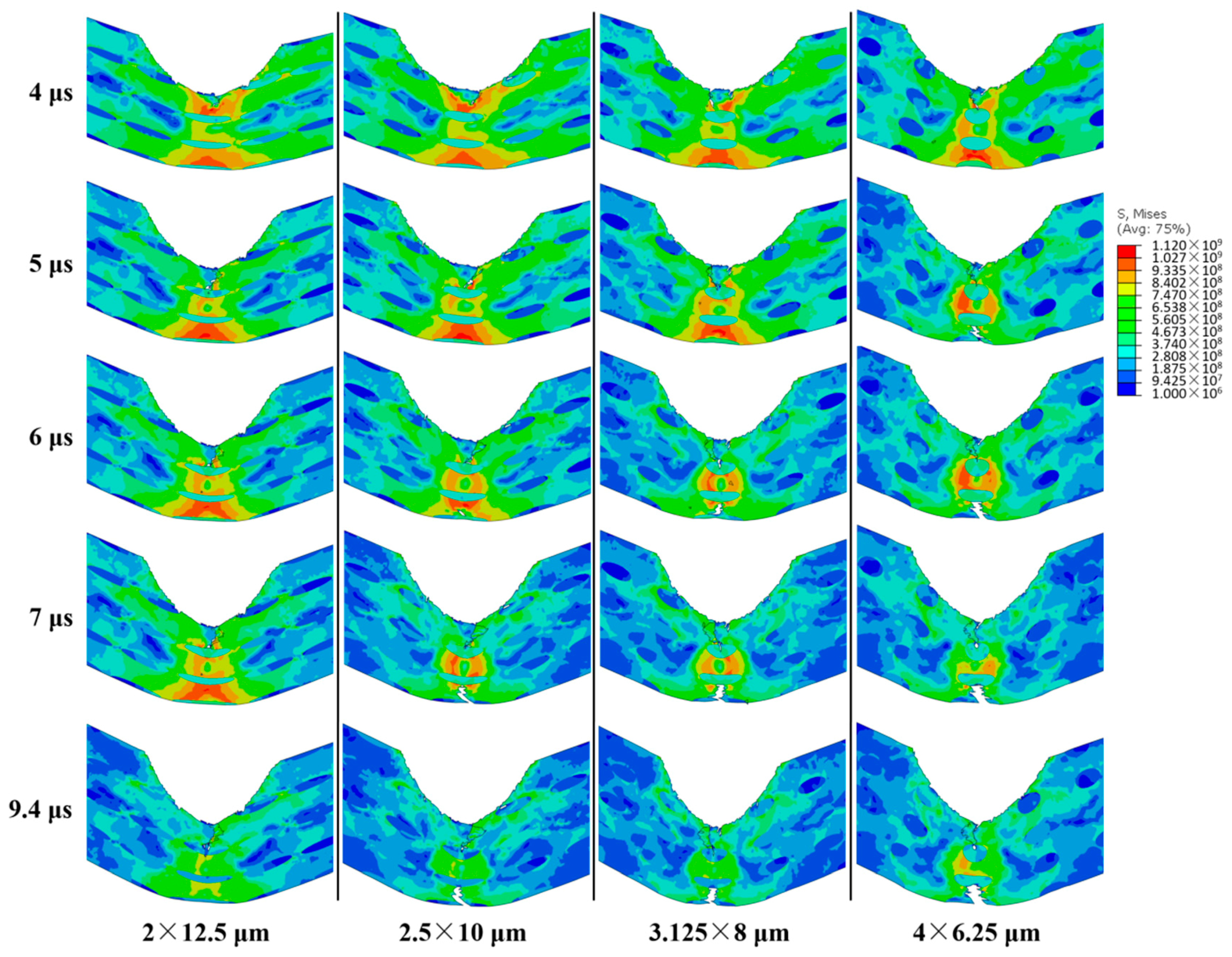
3.2. Effects of the Size of Elliptical CG Inclusions
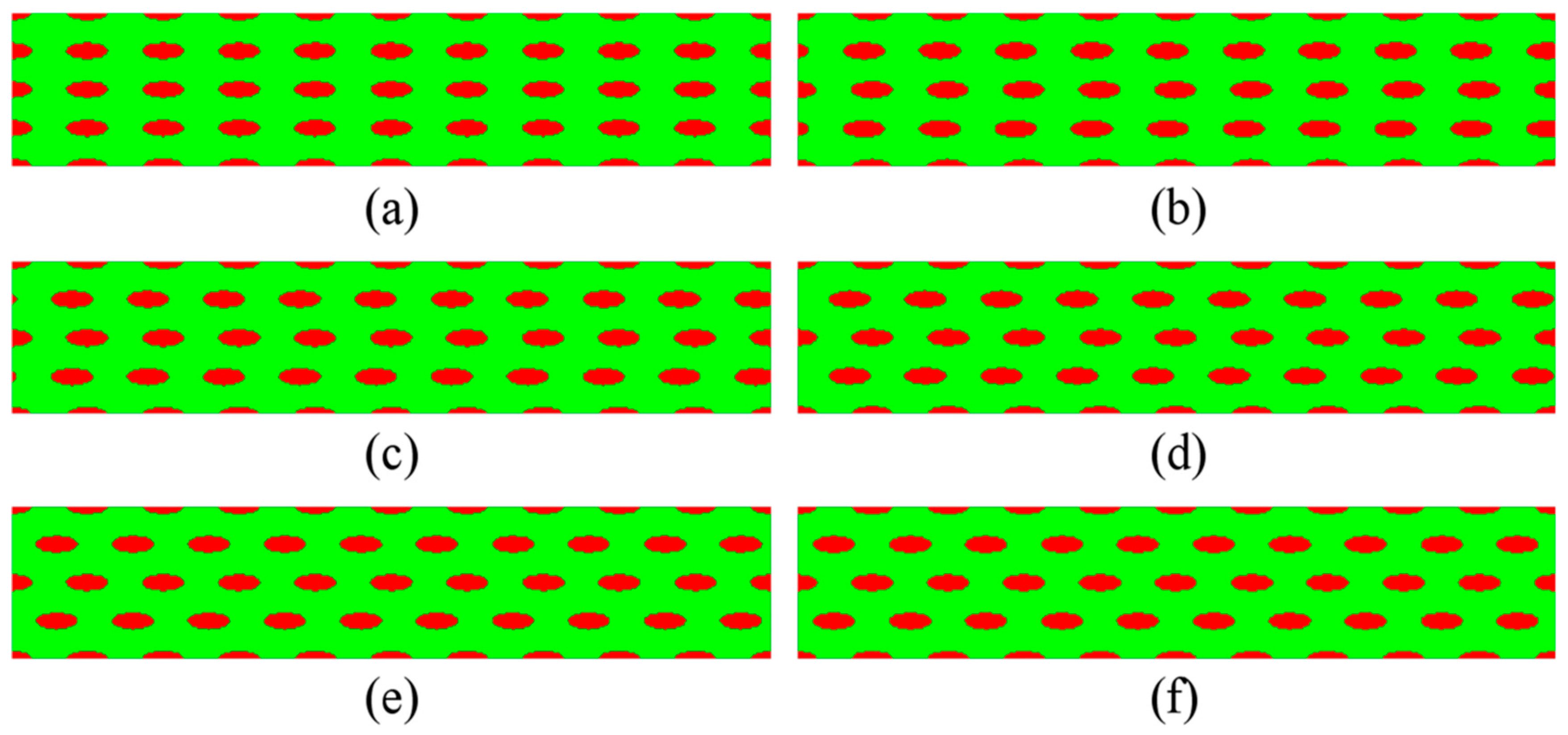
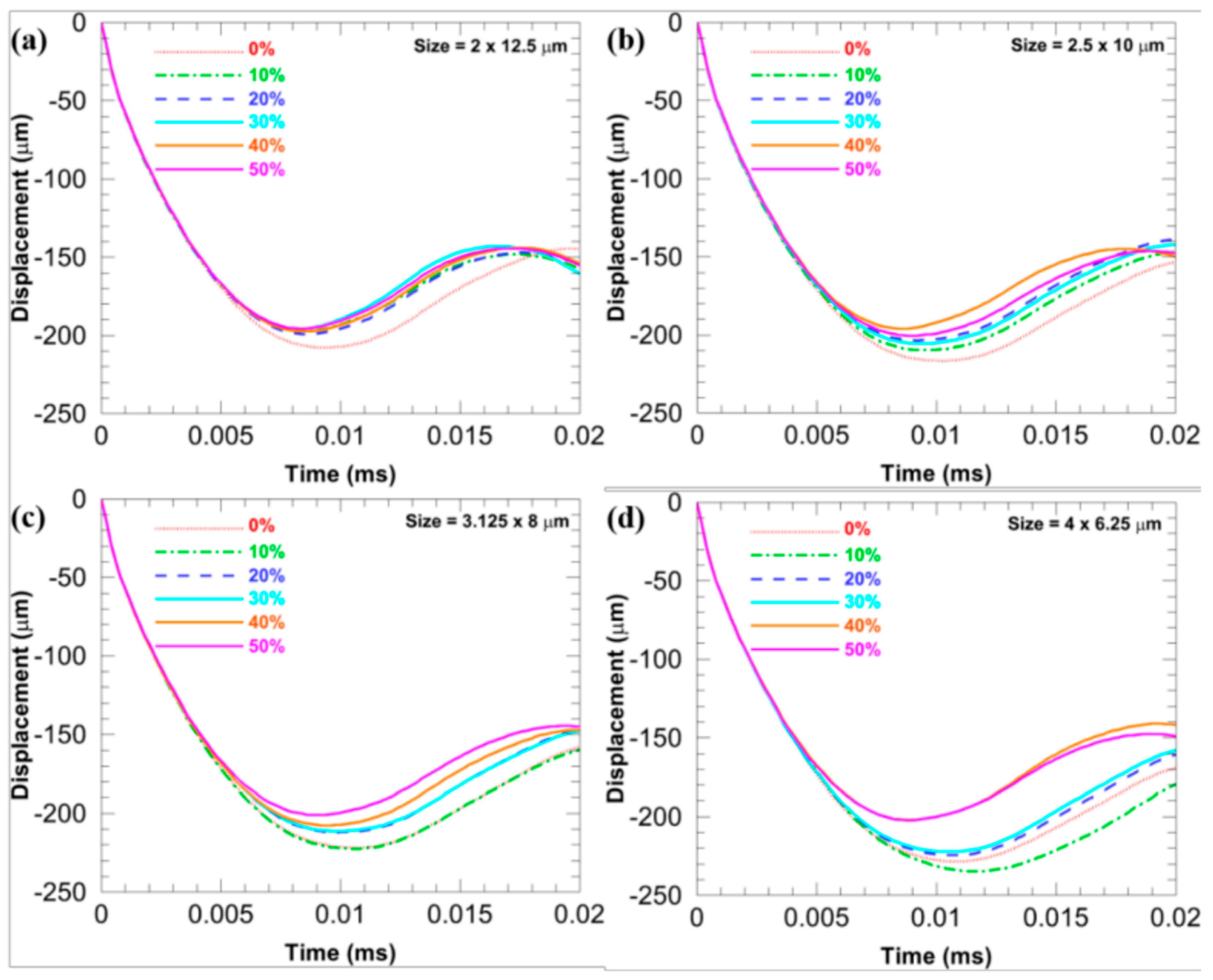
3.3. Effects of the Stagger Degree of Elliptical CG Inclusions
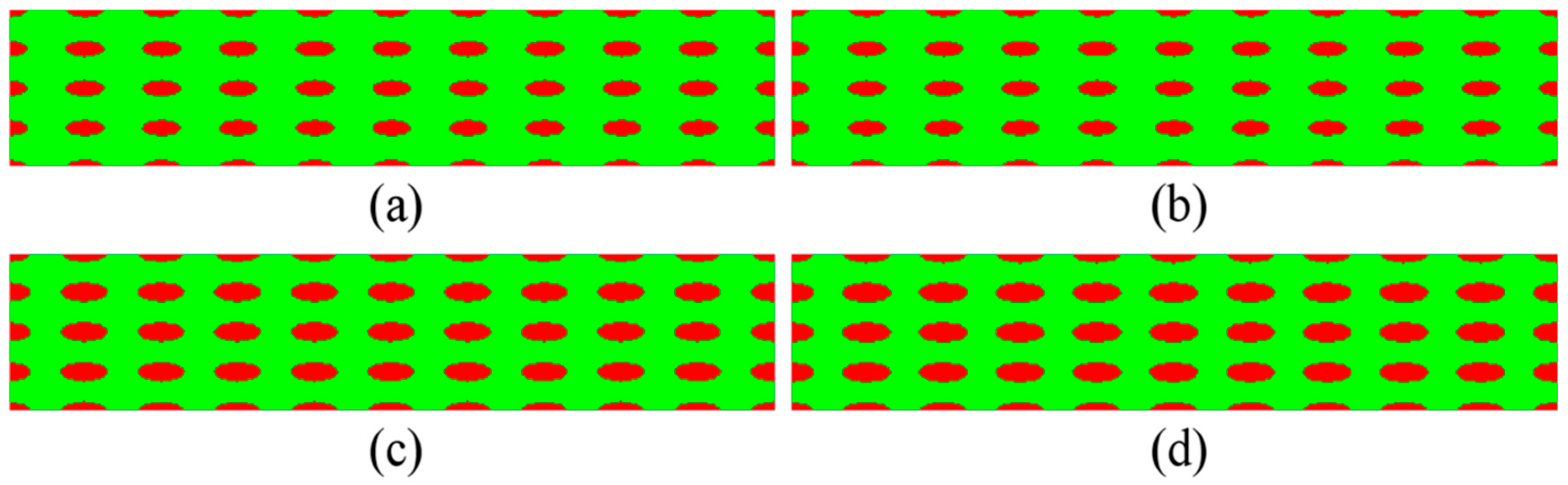
3.4. Effects of the Volume Fraction of Elliptical CG Inclusions
4. Conclusions and Outlooks
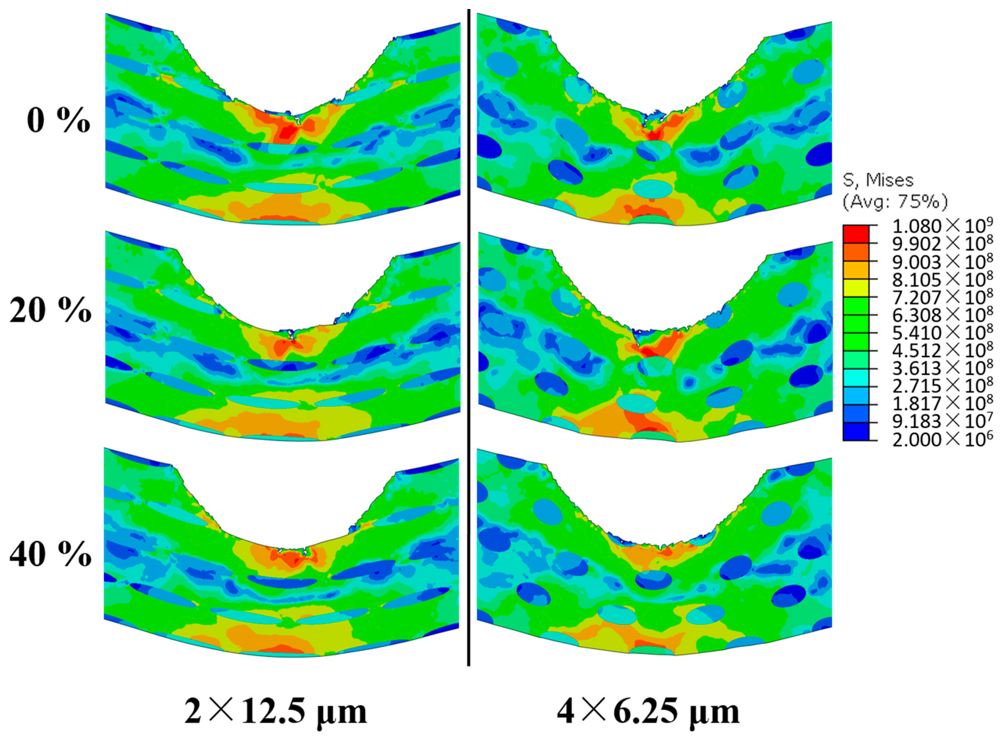
- The shape of elliptical CG inclusions significantly affects the overall ballistic performance. With a larger aspect ratio of elliptical CG inclusions, the ballistic performance of the microstructure is better.
- The distribution of elliptical CG inclusions also affects the overall ballistic performance. When the size is fixed at a given level and the volume fraction is also fixed, the increase in the stagger degree will weaken its ability to resist failure (this is the ductility issue) but will enhance its ability to resist deformation (this is the strength issue).
- Larger stagger degree can weaken the shape effects of elliptical CG inclusions on the overall limit velocity.
- The projection length of the adjacent CG inclusions along the central axis together with the stress distributions in the core region of the impact has significant effects on the overall ballistic performance.
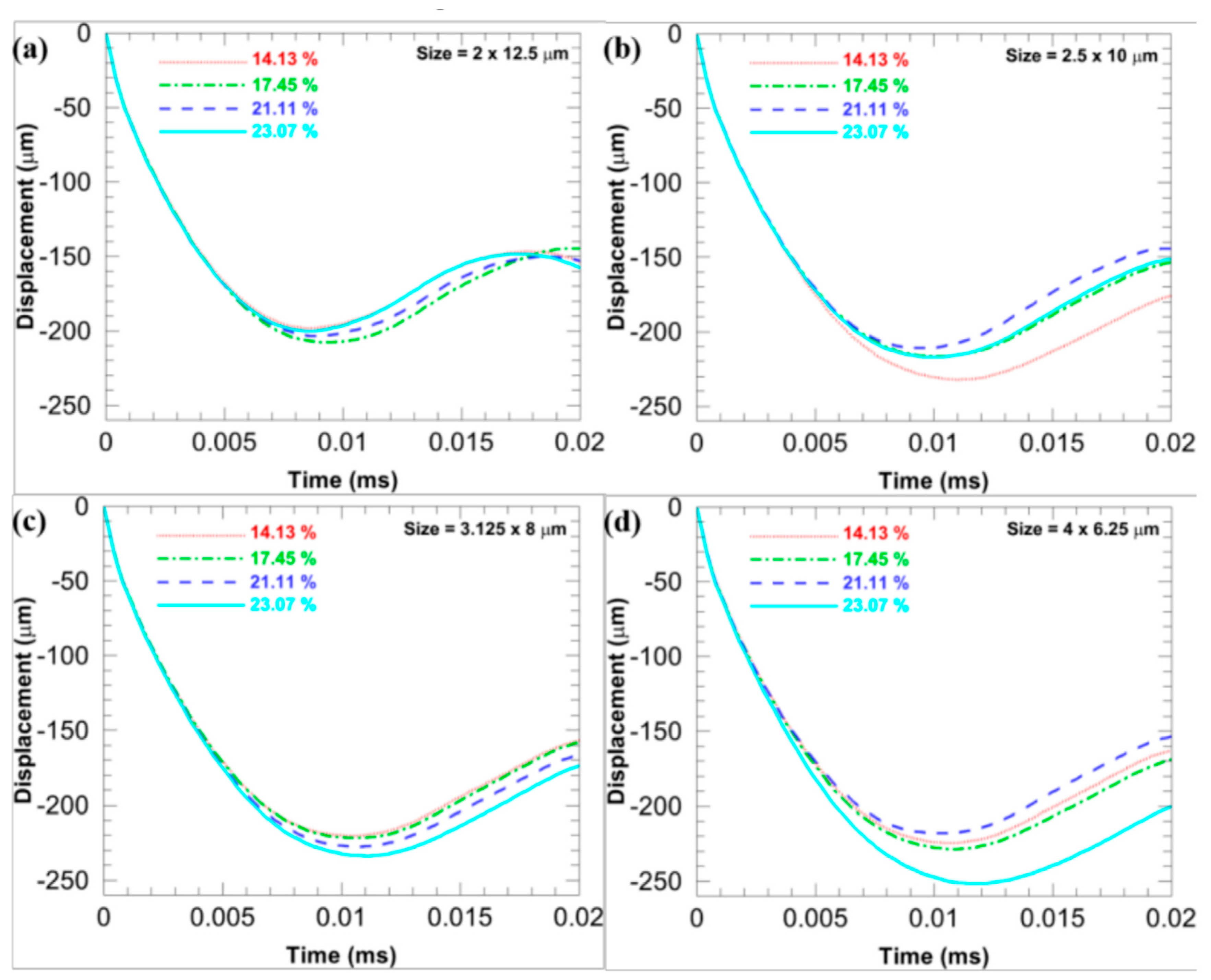
- An appropriate increase in the volume fraction of elliptical CG inclusions is helpful to enhance the ability of the microstructure to resist failure under ballistic impact.
Author Contributions
Funding
Acknowledgments
Conflicts of Interest
References
- Zhao, Y.H.; Topping, T.; Bingert, J.F.; Thornton, J.J.; Dangelewicz, A.M.; Li, Y.; Liu, W.; Zhu, Y.T.; Zhou, Y.Z.; Lavernia, E.J. High tensile ductility and strength in bulk nanostructured nickel. Adv. Mater. 2008, 20, 3028–3033. [Google Scholar] [CrossRef]
- Tellkamp, V.L.; Melmed, A.; Lavernia, E.J. Mechanical behavior and microstructure of a thermally stable bulk nanostructured Al alloy. Metall. Mater. Trans. A 2001, 32, 2335–2343. [Google Scholar] [CrossRef]
- Tellkamp, V.L.; Dallek, S.; Cheng, D.; Lavernia, E.J. Grain growth behavior of a nanostructured 5083 Al–Mg alloy. J. Mater. Res. 2001, 16, 938–944. [Google Scholar] [CrossRef]
- Lau, M.L.; He, J.; Schweinfest, R.; Rühle, M.; Levi, C.G.; Lavernia, E.J. Synthesis and characterization of nanocrystalline Cu–Al coatings. Mater. Sci. Eng. A Struct. 2003, 347, 231–242. [Google Scholar] [CrossRef]
- Witkin, D.V.; Lee, Z.; Rodriguez, R.; Nutt, S.; Lavernia, E.J. Al–Mg alloy engineered with bimodal grain size for high strength and increased ductility. Scr. Mater. 2003, 49, 297–302. [Google Scholar] [CrossRef]
- Gianola, D.S.; Petegem, S.V.; Legros, M.; Brandstetter, S.; Swygenhoven, H.V.; Hemker, K.J. Stress-assisted discontinuous grain growth and its effect on the deformation behavior of nanocrystalline aluminum thin films. Acta Mater. 2006, 54, 2253–2263. [Google Scholar] [CrossRef]
- Fan, G.J.; Choo, H.; Liaw, P.K.; Lavernia, E.J. Plastic deformation and fracture of ultrafine-grained Al–Mg alloys with a bimodal grain size distribution. Acta Mater. 2006, 54, 1759–1766. [Google Scholar] [CrossRef]
- Zhang, Z.H.; Han, B.Q.; Chung, K.H.; Lavernia, E.J. On the behavior of microstructures with multiple length scales. Metall. Mater. Trans. A 2006, 37, 2265–2273. [Google Scholar] [CrossRef]
- Wang, T.S.; Zhang, F.C.; Zhang, M. A novel process to obtain ultrafine-grained low carbon steel with bimodal grain size distribution for potentially improving ductility. Mater. Sci. Eng. A Struct. 2008, 485, 456–460. [Google Scholar] [CrossRef]
- Xia, S.H.; Vychigzhanina, L.V.; Wang, J.T.; Alexandrov, I.V.; Sharafutdinov, A.V. Controllable bimodal structures in hypo-eutectoid Cu–Al alloy for both high strength and tensile ductility. Mater. Sci. Eng. A Struct. 2008, 490, 471–476. [Google Scholar] [CrossRef]
- Ertorer, O.; Topping, T.D.; Li, Y.; Moss, W.; Lavernia, E.J. Nanostructured Ti consolidated via spark plasma sintering. Metall. Mater. Trans. A 2011, 42, 964–973. [Google Scholar] [CrossRef]
- Bui, Q.H. Heterogeneous plastic deformation in bimodal bulk ultrafine-grained nickel. J. Mater. Sci. 2012, 47, 1902–1909. [Google Scholar] [CrossRef]
- Magee, A.; Ladani, L.; Topping, T.D.; Lavernia, E.J. Effects of tensile test parameters on the mechanical properties of a bimodal Al–Mg alloy. Acta Mater. 2012, 60, 5838–5849. [Google Scholar] [CrossRef]
- Park, H.W.; Yanagimoto, J. Formation process and mechanical properties of 0.2% carbon steel with bimodal microstructures subjected to heavy-reduction single-pass hot/warm compression. Mater. Sci. Eng. A Struct. 2013, 567, 29–37. [Google Scholar] [CrossRef]
- Zhang, Z.; Orlov, D.; Vajpai, S.K.; Tong, B.; Ameyama, K. Importance of bimodal structure topology in the control of mechanical properties of a stainless steel. Adv. Eng. Mater. 2015, 17, 791–795. [Google Scholar] [CrossRef]
- Han, B.Q.; Lavernia, E.J.; Mohamed, F.A.; Bampton, C.C. Improvement of toughness and ductility of a cryomilled Al-Mg alloy via microstructural modification. Metall. Mater. Trans. A 2005, 36, 2081–2091. [Google Scholar] [CrossRef]
- Lee, Z.; Witkin, D.B.; Radmilovic, V.; Lavernia, E.J.; Nutt, S.R. Bimodal microstructure and deformation of cryomilled bulk nanocrystalline Al–7.5Mg alloy. Mater. Sci. Eng. A Struct. 2005, 410, 462–467. [Google Scholar] [CrossRef]
- Newbery, A.P.; Nutt, S.R.; Lavernia, E.J. Multi-scale Al 5083 for military vehicles with improved performance. JOM 2006, 58, 56–61. [Google Scholar] [CrossRef]
- Han, B.Q.; Huang, J.Y.; Zhu, Y.T.; Lavernia, E.J. Strain rate dependence of properties of cryomilled bimodal 5083 Al alloys. Acta Mater. 2006, 54, 3015–3024. [Google Scholar] [CrossRef]
- Lavernia, E.J.; Han, B.Q.; Schoenung, J.M. Cryomilled nanostructured materials: Processing and properties. Mater. Sci. Eng. A Struct. 2008, 493, 207–214. [Google Scholar] [CrossRef]
- Lee, Z.; Radmilovic, V.; Ahn, B.; Lavernia, E.J.; Nutt, S.R. Tensile deformation and fracture mechanism of bulk bimodal ultrafine-grained Al-Mg alloy. Metall. Mater. Trans. A 2010, 41, 795–801. [Google Scholar] [CrossRef]
- Wang, Y.; Chen, M.; Zhou, F.; Ma, E. High tensile ductility in a nanostructured metal. Nature 2002, 419, 912–915. [Google Scholar] [CrossRef] [PubMed]
- Yang, D.K.; Hodgson, P.D.; Wen, C.E. Simultaneously enhanced strength and ductility of titanium via multimodal grain structure. Scr. Mater. 2010, 63, 941–944. [Google Scholar] [CrossRef]
- Zhang, Z.; Rifai, M.; Kobayakawa, H.; Ciuca, O.P.; Fujiwara, H.; Ueno, A.; Ameyama, K. Effects of SiO2 particles on deformation of mechanically milled water-atomized SUS304L powder compacts. Mater. Trans. 2012, 53, 109–115. [Google Scholar] [CrossRef]
- Zhang, Z.; Vajpai, S.K.; Orlov, D.; Ameyama, K. Improvement of mechanical properties in SUS304L steel through the control of bimodal microstructure characteristics. Mater. Sci. Eng. A Struct. 2014, 598, 106–113. [Google Scholar] [CrossRef] [Green Version]
- Zhao, Y.; Topping, T.; Li, Y.; Lavernia, E.J. Strength and ductility of bi-modal Cu. Adv. Eng. Mater. 2011, 13, 865–871. [Google Scholar] [CrossRef]
- Joshi, S.P.; Ramesh, K.T.; Han, B.Q.; Lavernia, E.J. Modeling the constitutive response of bimodal metals. Metall. Mater. Trans. A 2006, 37, 2397–2404. [Google Scholar] [CrossRef]
- Berbenni, S.; Favier, V.; Berveiller, M. Impact of the grain size distribution on the yield stress of heterogeneous materials. Int. J. Plast. 2007, 23, 114–142. [Google Scholar] [CrossRef]
- Zheng, C.; Wang, F.; Cheng, X.; Fu, K.; Liu, J.; Wang, Y.; Liu, T.; Zhu, Z. Effect of microstructures on ballistic impact property of Ti–6Al–4V targets. Mater. Sci. Eng. A Struct. 2014, 608, 53–62. [Google Scholar] [CrossRef]
- Guo, X.; Dai, X.Y.; Zhu, L.L.; Lu, J. Numerical investigation of fracture behavior of nanostructured Cu with bimodal grain size distribution. Acta Mech. 2014, 225, 1093–1106. [Google Scholar] [CrossRef]
- Guo, X.; Ji, R.; Weng, G.J.; Zhu, L.L.; Lu, J. Micromechanical simulation of fracture behavior of bimodal nanostructured metals. Mater. Sci. Eng. A Struct. 2014, 618, 479–489. [Google Scholar] [CrossRef]
- Guo, X.; Yang, G.; Weng, G.J.; Zhu, L.L. Numerical simulation of ballistic performance of bimodal nanostructured metals. Mater. Sci. Eng. A Struct. 2015, 630, 13–26. [Google Scholar] [CrossRef]
- Ouyang, Q.D.; Guo, X.; Feng, X.Q. 3D microstructure-based simulations of strength and ductility of bimodal nanostructured metals. Mater. Sci. Eng. A Struct. 2016, 677, 76–88. [Google Scholar] [CrossRef]
- Guo, X.; Yang, G.; Weng, G.J.; Zhu, L.L.; Lu, J. Ballistic performance of bimodal nanostructured and nanotwin-strengthened metals. In Micromechanics and Nanomechanics of Composite Solids; Meguid, S.A., Weng, G.J., Eds.; Springer International Publisher: Basel, Switzerland, 2017; pp. 205–224. [Google Scholar]
- Witkin, D.; Han, B.Q.; Lavernia, E.J. Room-temperature mechanical behavior of cryomilled Al alloys. Metall. Mater. Trans. A 2006, 37, 185–194. [Google Scholar] [CrossRef]
- Ahn, B.; Newbery, A.P.; Lavernia, E.J.; Nutt, S.R. Effect of degassing temperature on the microstructure of a nanocrystalline Al–Mg alloy. Mater. Sci. Eng. A 2007, 463, 61–66. [Google Scholar] [CrossRef]
- ABAQUS/Explicit. ABAQUS Theory Manual and User’s Manual, Version 6.10; Dassault: Providence, RI, USA, 2013. [Google Scholar]
- Tandon, G.P.; Weng, G.J. The effect of aspect ratio of inclusions on the elastic properties of unidirectionally aligned composites. Polym. Compos. 1984, 5, 327–333. [Google Scholar] [CrossRef]
- Li, J.; Weng, G.J. A homogenization theory for the overall creep of isotropic viscoplastic composites. Acta Mech. 1997, 125, 141–153. [Google Scholar] [CrossRef]
- Li, J.; Weng, G.J. Anisotropic stress-strain relations and complex moduli of a viscoelastic composite with aligned inclusions. Compos. Eng. 1994, 4, 1073–1097. [Google Scholar] [CrossRef]
- Li, J.; Weng, G.J. Strain-rate sensitivity, relaxation behavior and complex moduli of a class of isotropic viscoelastic composites. J. Eng. Mater. Technol. 1994, 116, 495–504. [Google Scholar] [CrossRef]
- Zhu, L.L.; Lu, J. Modelling the plastic deformation of nanostructured metals with bimodal grain size distribution. Int. J. Plast. 2012, 30–31, 166–184. [Google Scholar] [CrossRef]
- Huang, Y.; Qu, S.; Hwang, K.C.; Li, M.; Gao, H.J. A conventional theory of mechanism-based strain gradient plasticity. Int. J. Plast. 2004, 20, 753–782. [Google Scholar] [CrossRef]
- Li, W.L.; Tao, N.R.; Lu, K. Fabrication of a gradient nano-micro-structured surface layer on bulk copper by means of a surface mechanical grinding treatment. Scr. Mater. 2008, 59, 546–549. [Google Scholar] [CrossRef]
- Johnson, G.R.; Cook, W.H. A constitutive model and data for metals subjected to large strains, high strain rates and high temperatures. In Proceedings of the 7th International Symposium on Ballistics, The Hague, The Netherlands, 19–21 April 1983. [Google Scholar]
- Johnson, G.R.; Cook, W.H. Fracture characteristics of three metals subjected to various strains, strain rates, temperatures and pressures. Eng. Fract. Mech. 1985, 21, 31–48. [Google Scholar] [CrossRef]
- Guduru, R.K.; Murty, K.L.; Youssef, K.M.; Scattergood, R.O.; Koch, C.C. Mechanical behavior of nanocrystalline copper. Mater. Sci. Eng. A 2007, 463, 14–21. [Google Scholar] [CrossRef]
- Ouyang, Q.D.; Weng, G.J.; Soh, A.K.; Guo, X. Influences of nanotwin volume fraction on the ballistic performance of coarse-grained metals. Theor. Appl. Mech. Lett. 2017, 7, 265–268. [Google Scholar] [CrossRef]
- Ouyang, Q.D.; Soh, A.K.; Weng, G.J.; Zhu, L.L.; Guo, X. The limit velocity and limit displacement of nanotwin-strengthened metals under ballistic impact. Acta Mech. 2017, 229, 1741–1757. [Google Scholar] [CrossRef]
- Frontan, J.; Zhang, Y.; Dao, M.; Lu, J.; Galvez, F.; Jerusalem, A. Ballistic performance of nanocrystalline and nanotwinned ultrafine crystal steel. Acta Mater. 2012, 60, 1353–1367. [Google Scholar] [CrossRef] [Green Version]
- Nguyen, T.H.A.; Bui, T.Q.; Hirose, S. Smoothing gradient damage model with evolving anisotropic nonlocal interactions tailored to low-order finite elements. Comput. Methods Appl. Mech. Eng. 2018, 328, 498–541. [Google Scholar] [CrossRef]


| f | Group I | Group II | Group III | Group IV |
|---|---|---|---|---|
| 14.13% | 1.8 × 11.25 μm | 2.25 × 9 μm | 2.8125 × 7.2 μm | 3.6 × 5.625 μm |
| 17.45% | 2 × 12.5 μm | 2.5 × 10 μm | 3.125 × 8 μm | 4 × 6.25 μm |
| 21.11% | 2.2 × 13.75 μm | 2.75 × 11 μm | 3.4375 × 8.8 μm | 4.4 × 6.875 μm |
| 23.07% | 2.3 × 14.375 μm | 2.875 × 11.5 μm | 3.59375 × 9.2 μm | 4.6 × 7.1875 μm |
© 2018 by the authors. Licensee MDPI, Basel, Switzerland. This article is an open access article distributed under the terms and conditions of the Creative Commons Attribution (CC BY) license (http://creativecommons.org/licenses/by/4.0/).
Share and Cite
Guo, X.; Ouyang, Q.; Sun, Y.; Weng, G.J. Ballistic Performance of Nanostructured Metals Toughened by Elliptical Coarse-Grained Inclusions: A Finite Element Study with Failure Analysis. Materials 2018, 11, 977. https://doi.org/10.3390/ma11060977
Guo X, Ouyang Q, Sun Y, Weng GJ. Ballistic Performance of Nanostructured Metals Toughened by Elliptical Coarse-Grained Inclusions: A Finite Element Study with Failure Analysis. Materials. 2018; 11(6):977. https://doi.org/10.3390/ma11060977
Chicago/Turabian StyleGuo, Xiang, Qidong Ouyang, Yubo Sun, and George J. Weng. 2018. "Ballistic Performance of Nanostructured Metals Toughened by Elliptical Coarse-Grained Inclusions: A Finite Element Study with Failure Analysis" Materials 11, no. 6: 977. https://doi.org/10.3390/ma11060977