Broadband Polarization Conversion Metasurface Based on Metal Cut-Wire Structure for Radar Cross Section Reduction


1
School of Optical and Electronic Information, Huazhong University of Science and Technology, Wuhan 430074, China
2
School of Information Science and Engineering, Wuhan University of Science and Technology, Wuhan 430081, China
*
Authors to whom correspondence should be addressed.
Materials 2018, 11(4), 626; https://doi.org/10.3390/ma11040626
Submission received: 13 March 2018
/
Revised: 12 April 2018
/
Accepted: 17 April 2018
/
Published: 19 April 2018
(This article belongs to the Section Advanced Materials Characterization)
Abstract
:A class of linear polarization conversion coding metasurfaces (MSs) based on a metal cut-wire structure is proposed, which can be applied to the reduction properties of radar cross section (RCS). We firstly present a hypothesis based on the principle of planar array theory, and then verify the RCS reduction characteristics using linear polarization conversion coding MSs by simulations and experiments. The simulated results show that in the frequency range of 6–14 GHz, the linear polarization conversion ratio reaches a maximum value of 90%, which is in good agreement with the theoretical predictions. For normal incident x- and y-polarized waves, RCS reduction of designed coding MSs 01/01 and 01/10 is essentially more than 10 dB in the above-mentioned frequency range. We prepare and measure the 01/10 coding MS sample, and find that the experimental results in terms of reflectance and RCS reduction are in good agreement with the simulated ones under normal incidence. In addition, under oblique incidence, RCS reduction is suppressed as the angle of incidence increases, but still exhibits RCS reduction effects in a certain frequency range. The designed MS is expected to have valuable potential in applications for stealth field technology.
1. Introduction
As a subwavelength artificial composite, metamaterial (MM) has some exotic electromagnetic (EM) properties that are unavailable in nature [1,2,3,4]. Research on MM has inspired many novel applications, including perfect lens imaging, inverse doppler effect, abnormal tunneling and many other phenomena [5,6,7,8,9,10]. As a two-dimensional (2D) planar form of MM [11,12,13,14,15], metasurfaces (MS) are constituted of subwavelength element arrays and have superior performance in tailoring the EM waves, which can be used to control the reflection/refraction wavefront in a smaller size range. By designing an artificial structure on the interface, the propagation and polarization characteristics of the EM wave regulation can be realized [16,17,18,19,20,21]. Therefore, the MS has prospects for potential application in polarization manipulation [22,23,24,25,26,27,28,29], high-performance antennas [30,31], and so on [32,33,34,35,36,37,38,39].
Radar stealth technology is concerned with reducing the target radar echo signal to achieve stealth, and radar cross section (RCS) area is an important physical quantity for measuring the radar echo capability of a target. RCS can be effectively reduced by using a MS designed with a suitable supper-unit structure [40,41,42]. As an important branch of MS, phase gradient MS (GMS) can be used to reduce the RCS by introducing an artificial wave vector at an in-plane direction to control the propagation direction of transmitted and reflected wave beams. Wu et al. proposed a GMS based on a cruciform structure, which could be applied to RCS reduction at low frequency ranges [43]. This designed MS has the defect of a narrow band range.
Recently, the concept of “coding MS” based on GMS was proposed by Cui et al. [44], and indicates a new manner for designing MS. The basic units are arranged on a matrix, and the phase responses of elements like 0 and π can be regarded as digitally “0” and “1”. Coding MS can diffuse the energy of EM waves in each direction by optimizing the matrix arrangement. This coding MS exhibits a broadband characteristic compared with traditional GMS, but still has the disadvantage of polarization-sensitivity. Based on the above research, we designed a series of coding MSs, one of which has the characteristics of a wide band range and polarization insensitivity, meaning that it promotes the RCS reduction of incident EM waves in all polarization directions. The traditional absorber can absorb electromagnetic waves and convert them into heat energy, which will be detected by infrared devices. The RCS reduction mechanism of the designed MS is different from the absorber; by designing the structure graphics and coding scheme, the incident waves are reflected irregularly back into free space, which lowers the probability of the MS being detected by infrared devices. Therefore, the scattering energy of each directional beam is small, which can achieve an effective RCS reduction at different angles [45,46,47,48,49,50,51,52].
The metal cut-wire structure (rectangular strip structure) is advantageous in terms of its simple structure, the adjustability of its geometric parameters, and has a wide application with respect to the design of MMs and MSs. In this work, we apply it as the basic unit structure for the design of a broadband linear polarization conversion MS. We can obtain the required phase difference by rotating the metal cut-wire structure by 90° along the propagation direction, and the phase response of the two basic units are 0 and π, denoted by “0” and “1”, respectively. At the same time, we design a class of 1-bit coding form to focus on the RCS reduction characteristics of the polarization conversion MS. The designed MS presents the characteristics of a broadband range, polarization-insensitivity, and wide incidence angle. For normal x/y-polarized incidence, both simulations and experiments show that the RCS of the MS is reduced by an average of 10 dB in the frequency range of 6–14 GHz. Meanwhile, at oblique incidence, RCS reduction is suppressed, but still has a certain effect in the above-mentioned frequency range.
2. Design of Basic Unit and Theoretical Analysis
In this paper, we present a basic unit based on a metal cut-wire structure, which we assume to be a “0” unit, as shown in Figure 1a. The whole unit-cell is divided into three functional layers, where the period is p = 10 mm. This design of the three functional layers can form a Fabry-Perot-like resonance cavity, consequently leading to interference of cross-polarization couplings in multi-reflection [21,22]. The front layer is the metal cut-wire structure of copper film; the length and width are l = 10 mm and w = 1.6 mm, respectively. The front layer cut-wire structure possesses a symmetric axis at 45° with respect to the x or y direction, such that a 90° polarization conversion can be achieved when the incident wave is x- or y-polarized. The middle layer dielectric substrate is FR4 film with a thickness of h = 3.5 mm; the side view is shown in Figure 1c. The dielectric constant is 4.3, and the loss tangent is 0.025. The back layer is continuous copper film and has the same thickness as the front metal structure, which is 0.035 mm. We rotated the metal cut-wire counterclockwise by 90° (Figure 1a) to obtain the MS unit structure, as shown in Figure 1b, which is set to “1”.
We used the frequency domain solver on the EM simulation software CST MICROWAVE STUDIO to obtain the co-polarization (rxx and ryy) and cross-polarization (ryx and rxy) reflection coefficients for both incident x-polarized and y-polarized waves. As suggested by the reflection coefficients in Figure 1d, the structure is able to achieve efficient linear polarization conversion across a wide frequency range of 6–14 GHz, the cross-polarization reflection coefficients (ryx and rxy) are greater than 0.85, and the co-polarization reflection coefficients (rxx and ryy) are substantially less than 0.3. In addition, at resonance frequencies, the co-polarization reflection coefficients (rxx and ryy) reach a minimum, and the corresponding amplitudes are less than 0.1. The corresponding cross-polarization reflection coefficients (ryx and rxy) reach a maximum, and the amplitudes are greater than 0.9. This result indicates that the normal incident x(y)-polarized waves are almost completely converted to y (x)-polarized waves, or produced approximately 90° linear polarization deflections.
In order to visually reflect the polarization conversion capability of the MS, we define the polarization conversion efficiency as follows [22,23]: PCRx = |ryx|2/(|ryx|2 + |rxx|2) and PCRy = |rxy|2/(|rxy|2 + |ryy|2). In Figure 1f, the linear polarization conversion ratio of the x- and y-polarized waves are as high as 90% and reached 99% at resonance frequencies. Figure 1e,g shows the cross-polarization phases of the “0” and “1” units, and the corresponding phase difference, Δφ10(Δφxy), in the whole 4–16 GHz range. It is observed that the cross-polarization phase difference Δφ10(Δφxy) = ±180° can be obtained, which indicates that the phase gradient of the designed MS is 180°.
This basic unit has excellent simulated results; mainly due to the front cut-wire structure layer and metal back layer forming a Fabry-Perot-like resonance cavity, we are able to observe the multiple reflections and transmissions in the Fabry-Perot-like resonance cavity as shown in Figure 2. The transmitted EM waves continue to travel in the dielectric spacer until they encounter the ground plane with a complex propagation phase , where k0 is the free space wavenumber, the and d are the relative permittivity and thickness of the middle dielectric layer. The partial reflection and transmission waves arrive at the air-spacer interface again from the reverse direction after the additional propagation phase β in the dielectric spacer [22]. The incident EM wave prompted multiple reflections in this resonance cavity, including co-polarization wave interference cancellation, and cross-polarization wave interference superposition. Based on our previous research [22], the cross-polarization and co-polarization reflection coefficients can be expressed as: and . Thus, we simulate the unit-cell structure without the ground plane, and use MATLAB software to calculate the reflection coefficients and polarization conversion ratio for the x-polarized wave incidence. As shown in Figure 3a,b, the calculated data are in reasonable agreement with the simulated data, further illustrating the working principle of the Fabry-Perot-like resonance cavity. Therefore, we can use the characteristics of the ±180° cross-polarization reflected phase difference based on the metal cut-wire structure elements “0” and “1” and realize polarization conversion by combining different coding combinations.
A traditional MS has a uniform reflection phase when a plane wave impinges on it, leading to a strong scattering pattern. In order to manipulate the reflected beam direction, a phase gradient is introduced into the interface to control the equiphase wavefront. To suppress the normal strong scattering of the MS, the simplest way is to generate a matrix of designed phase distribution. We propose a series of polarization conversion coding MSs composed of “0” and “1” units, and make a hypothesis based on the principle of planar array theory [53,54]; then, we verify this derivation using data from the simulation. For a MS with A × B elements, the total scattering field can be expressed as [53]:
where EF represents the scattering field of the cell pattern; and AF represents the array factor, which can be expressed as [53]:
where θ is the angle between the incident wave and the z-axis along the XOZ-plane; φ is the angle between incident wave and x-axis along the XOY-plane; a and b represent the rows and columns of unit cell; k = 2π/λ, λ is the wavelength of incident wave; d is the distance between the units; and Φ (a, b) is the phase difference between the elements. As shown in Figure 4a, we put 01/10 code into 2 × 2 structure arrangement, each super-cell consists of 5 × 5 basic units; the scattering field can be expressed as:
where AF0 and AF1 are the elements “0” and “1”, respectively; and EF0 and EF1 are the scattering fields of the “0” and “1” elements, respectively. The array factor AF2×2 with a 2 × 2 arrangement can be expressed as:
For the 01/10 coding sequence, Φ(1,1) and Φ(2,2) correspond to the phase difference of 0°; Φ(1,2) is the 180° phase difference of two adjacent cells of column B, and Φ(1,2)→2kdsinθsinφ; Φ(2,1) is the 180° phase difference of two adjacent cells of row A, and Φ(1,2)→2kdsinθcosφ. Further derivation shows that the array factor of coding 01/10 is:
The above formula can be decomposed according to the arrangement of Figure 5a:
AF0 and AF1 are expressed in the matrices as shown below:
We can see that the first half of the matrix corresponds to the arrangement of the 01/10 coding structure, and the latter part of the matrix corresponds to the 0–1 phase difference distribution.
For the 01/01 coding sequence, the derivation method is similar to the one for the 01/10 coding sequence. For 2 × 2 coding MS, the area of the unit-cell structure is assumed to be 1. For normal incidence, the angles of incidence are θ = φ = 0°, coding 01/10 corresponds to AF0 = AF1 = 2/4 = 1/2. Similarly, coding 01/01 corresponds to AF0 = AF1 = 1/2.
Since the unit-cell structure has the characteristic of polarization conversion, the polarization direction of the incident wave is along the x-axis. For the normal incident field EFt, the incident fields EF0 and EF1 are expressed as:
where rxx = is the co-polarization reflection coefficient and ryx = is the cross-polarization reflection coefficient. From the previous simulated results, we can see that the units “0” and “1” have the same co-polarization reflection phase, and the cross-polarization reflection phase difference is 180°. Therefore, the total scattering field can be expressed as:
The size of the scattering field of the array structure is |Etotal| = rxx|EFt|. For a metal plate, the size of the scattering field is |EFitotal| = |EFt|, and the scattering coefficient is rxx = |Etotal|/|EFitotal|. We assume that the RCS reduction of the MS is greater than 10 dB, so the following condition needs to be met:
In summary, coding 01/01 and 01/10 have better RCS reduction characteristics under certain conditions compared with coding 00/00 and 11/11. Since the co-polarization and cross-polarization phases of 00/00 and 00/11 are consistent, the cross-polarization components of the scattering field can’t be offset, and RCS can’t be reduced; thus, the corresponding RCS reduction is 0. The next step is to verify this hypothesis by simulation.
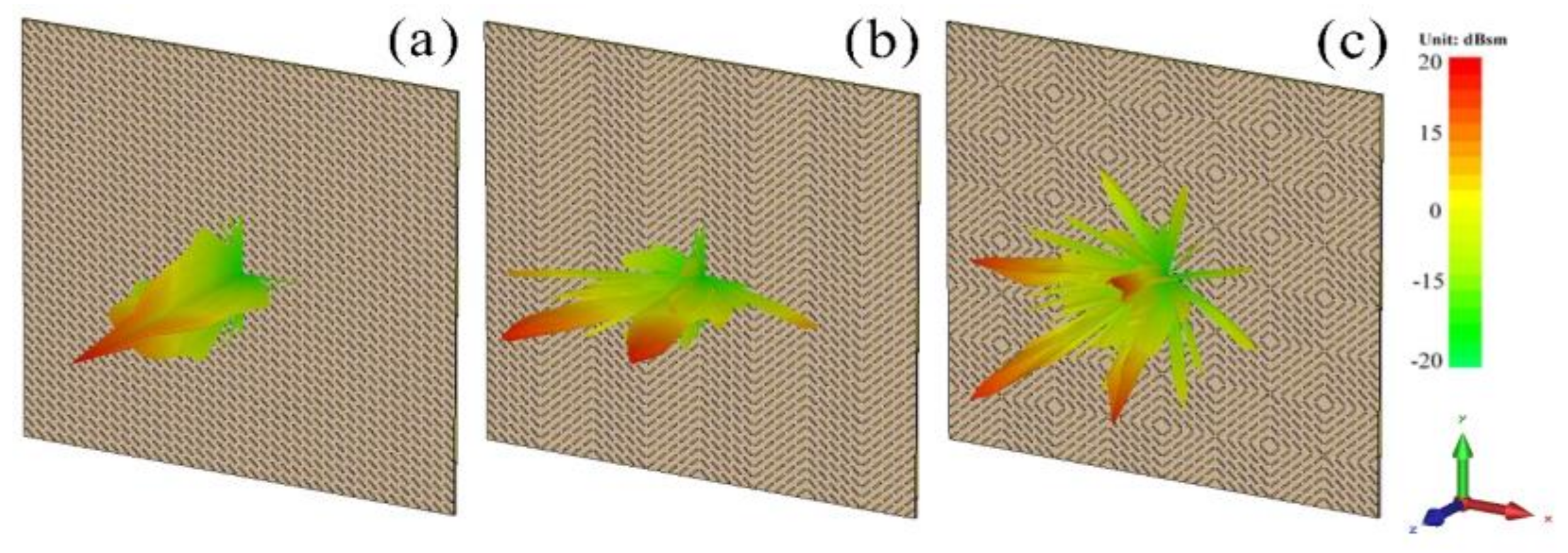
To meet the periodic boundary conditions required for simulation, we used a 5 × 5 basic unit as a super-cell and designed a series of coding forms to explore the polarization conversion characteristics of the MS. Figure 5a–c shows the far-field scattering characteristic diagram of each regular coding form at 10 GHz. The energy scattering direction of coding 00/00 or 11/11 is upright, and the normal scattering capability is very strong, suggesting that these coding MSs do not have characteristics of RCS reduction under normal incidence. The energy scattering of 01/01 and 10/10 are the same, diverging to both sides. The energy scattering of 01/10 diverges all around, and the normal scattering capacity is relatively weak. Thus, it can be expected that the 01/01 and 01/10 coding MSs have normal RCS reduction characteristics. Therefore, by controlling the coding method of the MS, it is possible to change the scattering direction of the energy. However, the coding 01/10 has polarization-insensitive properties compared to the coding 01/01. In order to meet the needs of practical applications, we focus on studying the MS of coding 01/10, and the schematic diagram is shown in Figure 4b.
3. Simulation, Experiment and Discussion
Using the frequency domain solver in the EM simulation software CST MICROWAVE STUDIO (2016, CST, Darmstadt, Germany), we perform a numerical simulation of three regular coding MSs, as shown in Figure 4. Firstly, for 01/10 coding MS, the RCS reduction characteristics of a super-cell with n × n basic units were discussed numerically; as shown in Figure 6a, the RCS reduction of 5 × 5 super-cell increases compared with a 3 × 3 or 1 × 1 super-cell, and the overall curves shift to the lower frequencies. With an increase in the number of units, the numerical RCS reduction gradually stabilizes. To meet the requirements of test conditions and practical application, a 5 × 5 supercell was selected as the basic coding unit for studying the RCS reduction characteristics. Figure 6b shows the RCS reduction in all arrangements under normal incidence, where the MSs of coding 01/01 and 01/10 achieve RCS reduction in a broadband range. In Figure 1d, the reflection coefficient of the basic unit is rxx = 0.318 > 0.316 at the 7.7 GHz peak, and rxx = 0.301 < 0.316 at the 12.2 GHz peak. According to Formula (10), we can see that the RCS reduction of the MS should be less than 10 dB around 7.7 GHz. Figure 6b also shows that the MSs of coding 01/01 and 01/10 have dips at the above-mentioned frequency, where RCS reduction is less than 10 dB around 7.7 GHz. For the MSs of coding 00/00 and 11/11, it can be seen that the RCS reduction is essentially zero in our frequency range of interest of 5–15 GHz. This is mainly due to the consistency of co-polarization and cross-polarization phases for all basic units, where the RCS of the target can’t be reduced since the cross-polarization components of the scattering field can’t be offset. These simulated results near perfectly verify the above analysis.
We simulated the RCS reduction of 01/01 and 01/10 coding MSs for the incidence of x-polarized and y-polarized waves, as shown in Figure 6c,d, respectively. In Figure 6c, the RCS reduction amplitude of the 01/01 coding MS is clearly different between the x- and y-polarized waves under normal incidence, indicating that the 01/01 coding MS has a certain polarized selection characteristic. As shown in Figure 6d, the RCS reduction curves of the 01/10 coding MS under x- and y-polarized waves are slightly different, but the trend is basically consistent under normal incidence, indicating that the coding MS exhibits a polarization-insensitive property. The 01/10 coding MS exhibits a near polarization-insensitive property, mainly due to its chessboard arrangement; the direction of electric field and magnetic field are relatively consistent with the incident x- and y-polarized waves. Hence, we can see the reflection coefficients of EM waves are basically the same. However, the 01/01 is asymmetric, and the direction of electric field and magnetic field are not consistent with the incident x- and y-polarized waves under the same incident surface. In addition, the RCS reduction of the 01/10 coding MS is greater than 10 dB on average throughout a wide frequency range of 6–14 GHz and is greater than 20 dB in the frequency range of 10–11 GHz. At 10.5 GHz, the RCS reduction reacches a maximum of 37 dB.
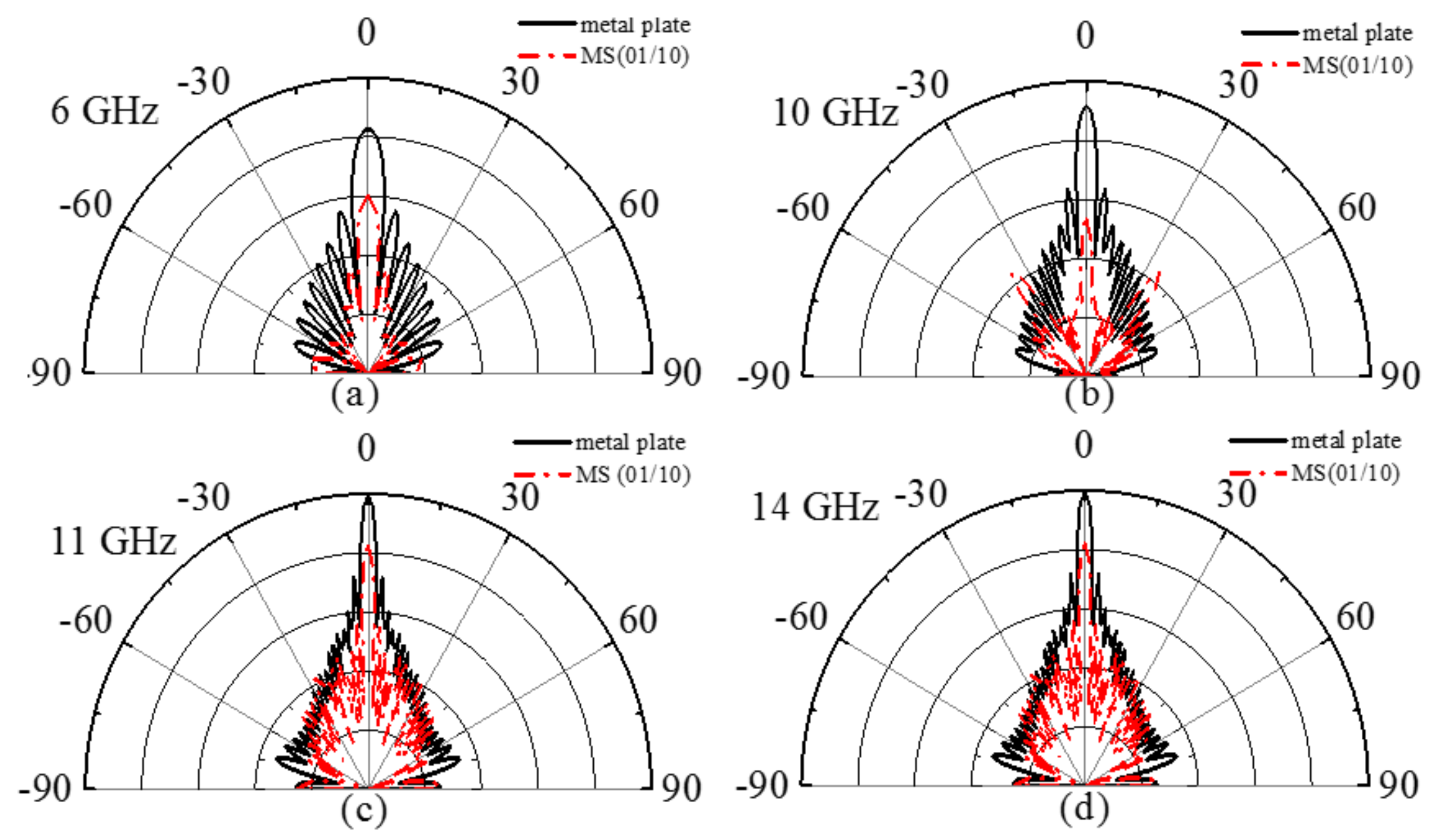
To further study the RCS reduction characteristics of 01/10 coding MS, we study the scattering pattern of the XOZ-plane under normal incidence, as shown in Figure 7a–d; where the scattering characteristics of the 01/10 coding MSs at 6 GHz, 10 GHz, 11 GHz, and 14 GHz are compared with a metal plate with the same size of 400 × 400 mm2. According to the law of energy conservation, the main lobe energy is suppressed significantly by enhancing the scattered energy of the side lobes to achieve RCS reduction under normal incidence. The pattern shows that the metal plate has a main lobe throughout the whole band under normal incidence. As shown in Figure 7a,d, relative to the metal plate, the MS has a certain inhibitory effect on the main lobe at 6 and 14 GHz, respectively. As shown in Figure 7b,c, the MS has an obvious inhibitory effect on the main lobe at 10 and 11 GHz, respectively. Based on the above results, it can be suggested that the polarization conversion MS can realize RCS reduction throughout a wide frequency range and can adjust the scattering field dynamically.
In order to further verify the RCS reduction characteristics of the polarization conversion coding MS, we fabricated a MS sample of 01/10 coding and measured it in a microwave anechoic chamber. A 400 × 400 mm2 sample was fabricated using traditional printed circuit board (PCB) technology, as shown in Figure 8a. The front and back layers of the sample are covered with copper, and the middle layer is a FR4 substrate with a thickness of 3.5 mm. Using the free space method, we measured the sample in the microwave anechoic chamber (see Figure 8b). The measured sample was fixed in the center of a rotating foam tower, the transmitter and receiver antennas were fixed to the same height, ensuring an angle of 5°. Then, we connected two horn antennas of co-polarization state to two ports of the Agilent Technologies N5244A Vector Analyzer and measured the RCS of the sample.
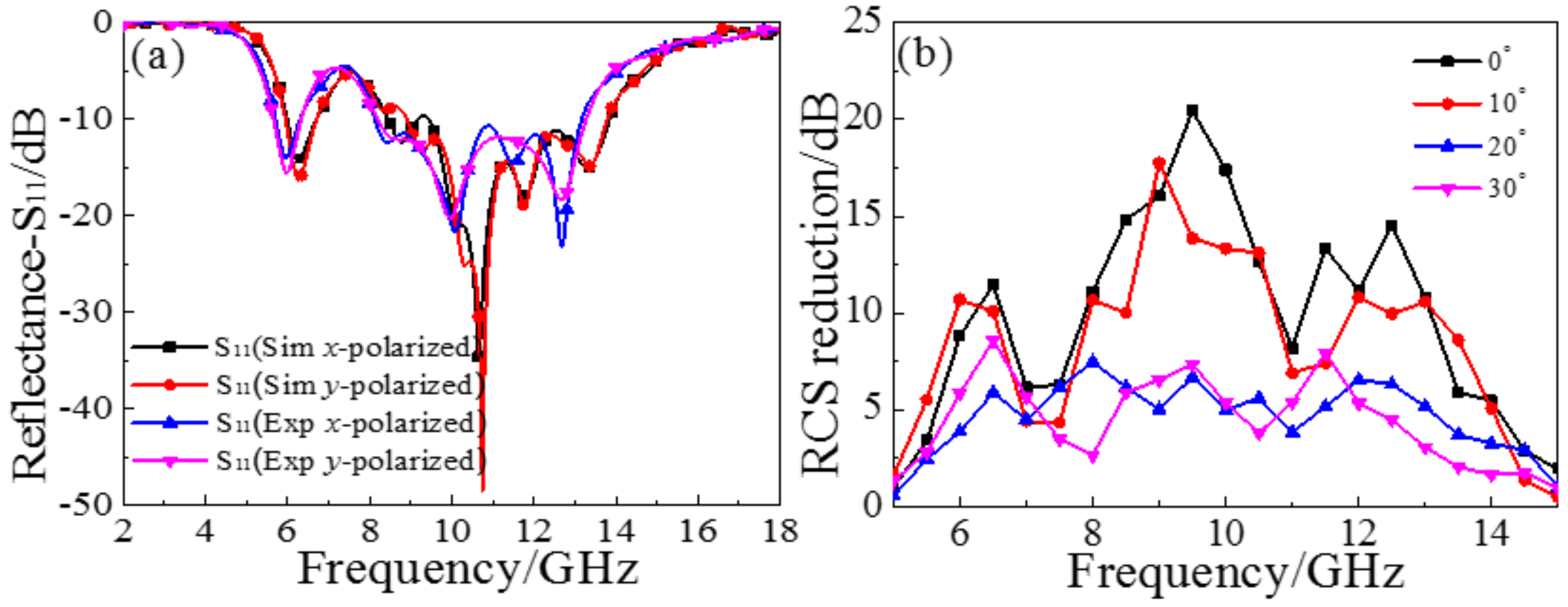
The reflectance of simulation and experiment under normal incident x- and y-polarized wave are shown in Figure 9a. Under the conditions of incident different polarization waves, the simulated results under x- and y-polarized incidence are basically coincident, as are the measured results, which reveals the near polarization insensitivity of the proposed MS. However, the results of the simulation and experiments are quite different at the main peak. The main reason behind this deviation may be the error occurring in the production of the sample, such as the inability to precisely control the thickness, or the sample not being completely flat. The simulated and measured reflectance (x- and y-polarization) near 7.7 GHz is slightly greater than −10 dB, which verifies the previous theoretical analysis, and the reflectance (x- and y-polarization) is below −5 dB in the frequency range of 5–14 GHz. Figure 9b shows the RCS reduction of the measured sample at different angles of incidence. At normal incidence, although there is a valley less than 10 dB near the 7.7 GHz, the RCS reduction is basically greater than 10 dB in the frequency range of 6–14 GHz. Under a small oblique incident angle, the RCS reduction curves of oblique incident angles from 0° to 10° are basically the same. When the incident angles reach 20° and 30°, RCS reduction fluctuate around 5 dB in the frequency range of 6–14 GHz. It can be seen that RCS reduction is suppressed as the angle increases, but still has a certain effect within the above frequency range.
4. Conclusions
In this work, a basic unit based on a metal cut-wire structure was designed, which allowed us to achieve the highly efficient conversion of linear polarization within a broadband frequency range. A hypothesis was proposed based on the principle of planar array theory and was verified by using the simulated data of the MS. Utilizing a super-cell consisting of 5 × 5 basic units, we studied the RCS reduction of the polarization conversion MS based on super-coding theory. By simply rotating the metal cut-wire structure, it is possible to realize the characteristics of “0” and “1” basic unit 180° cross-polarization reflected phase differences. This method avoids the need to change the graphic design size and makes it possible to arrange super-coding in an easy and efficient way. We simulated a series of coding forms to generate the RCS reduction graph and scattering pattern under normal incidence, further exploring the relationship of the coding MS with different arrangement modes and the energy scattering direction at the same time. The influence of polarization conversion characteristics for RCS reduction was also proved. Based on the simulated design, we fabricated a 01/10 coding MS sample and measured its reflectance and RCS reduction. The measured results are in good agreement with the simulation, which proves that the polarization conversion MS structure is able to realize the reduction of RCS. Our work proposes a new design as a basis for future studies on RCS reduction of MSs, which has potential application in stealth field technology.
Acknowledgments
This work is supported by the National Natural Science Foundation of China (U1435209, 61605147 and 61701185), and the Natural Science Foundation of Hubei province (Grant No. 2017CFB588).
Author Contributions
Jia Ji Yang and Yong Zhi Cheng conceived and designed the experiments; Jia Ji Yang and Chen Chen Ge performed the experiments; Jia Ji Yang and Yong Zhi Cheng analyzed the data; Yong Zhi Cheng and Rong Zhou Gong contributed reagents/materials/analysis tools; Jia Ji Yang wrote the paper.
Conflicts of Interest
The authors declare no conflict of interest.
References
- Pendry, J.B.; Schurig, D.; Smith, D.R. Controlling electromagnetic fields. Science 2006, 312, 1780–1782. [Google Scholar] [CrossRef] [PubMed]
- Martin, F.; Falcone, F.; Bonache, J.; Marques, R. Miniaturized coplanar waveguide stop band filters based on multiple tuned split ring resonators. IEEE Microw. Wirel. Compon. Lett. 2003, 13, 511–513. [Google Scholar] [CrossRef]
- Smith, D.R.; Pendry, J.B.; Wiltshire, M.C.K. Metamaterials and negative refractive index. Science 2004, 305, 788–792. [Google Scholar] [CrossRef] [PubMed]
- Engheta, N. Circuits with light at nanoscales: Optical nanocircuits inspired by metamaterials. Science 2007, 317, 1698–1702. [Google Scholar] [CrossRef] [PubMed]
- Alù, A.; Engheta, N. Achieving transparency with plasmonic and metamaterial coatings. Phys. Rev. E 2005, 72, 016623. [Google Scholar] [CrossRef] [PubMed]
- Monticone, F.; Estakhri, N.M.; Alù, A. Full control of nanoscale optical transmission with a composite metascreen. Phys. Rev. Lett. 2013, 110, 203903. [Google Scholar] [CrossRef] [PubMed]
- Shelby, R.A.; Smith, D.R.; Schultz, S. Experimental verification of a negative index of refraction. Science 2001, 292, 77–79. [Google Scholar] [CrossRef] [PubMed]
- Pendry, J.B. Negative refraction makes a perfect lens. Phys. Rev. Lett. 2000, 85, 3966. [Google Scholar] [CrossRef] [PubMed]
- Xu, H.X.; Tang, S.W.; Ling, X.H.; Luo, W.J.; Zhou, L. Flexible control of highly-directive emissions based on bifunctional metasurfaces with low polarization cross-talking. Ann. Phys. Berl. 2017, 529. [Google Scholar] [CrossRef]
- Alrasheed, S.; Fabrizio, E.D. Design and simulation of reflect-array metasurfaces in the visible regime. Appl. Opt. 2017, 56, 3213–3218. [Google Scholar] [CrossRef] [PubMed]
- Cheng, Y.Z.; Cheng, Z.Z.; Mao, X.S.; Gong, R.Z. Ultra-thin multi-band polarization-insensitive microwave metamaterial absorber based on multiple-order responses using a single resonator structure. Materials 2017, 10, 1241. [Google Scholar] [CrossRef] [PubMed]
- Cheng, Y.Z.; Wu, C.J.; Ge, C.C.; Yang, J.J.; Pei, X.J.; Jia, F.; Gong, R.Z. An ultra-thin dual-band phase-gradient metasurface using hybrid resonant structures for backward RCS reduction. Appl. Phys. B 2017, 123, 143. [Google Scholar] [CrossRef]
- Li, Y.F.; Wang, J.; Zhang, J.; Qu, S.B.; Pang, Y.Q.; Zheng, L.; Yan, M.B.; Xu, Z.; Zhang, A.X. Ultra-wide-band microwave composite absorbers based on phase gradient metasurfaces. Prog. Electromagn. Res. 2014, 40, 9–18. [Google Scholar] [CrossRef]
- Xu, H.X.; Ma, S.J.; Luo, W.J.; Cai, T.; Sun, S.L.; He, Q.; Zhou, L. Aberration-free and functionality-switchable meta-lenses based on tunable metasurfaces. Appl. Phys. Lett. 2016, 109, 193506. [Google Scholar] [CrossRef]
- Fan, Y.C.; Liu, Z.; Zhang, F.L.; Zhao, Q.; Wei, Z.Y.; Fu, Q.H.; Li, J.J.; Gu, C.Z.; Li, H.Q. Tunable mid-infrared coherent perfect absorption in a graphene meta-surface. Sci. Rep. 2015, 5, 13956. [Google Scholar] [CrossRef] [PubMed]
- Tian, S.; Liu, H.; Li, L. Design of 1-bit digital reconfigurable reflective metasurface for beam-scanning. Appl. Sci. Basel 2017, 7, 882. [Google Scholar] [CrossRef]
- Lee, S.H.; Choi, M.; Kim, T.T.; Lee, S.; Liu, M.; Yin, X.; Choi, H.K.; Lee, S.S.; Choi, C.G.; Choi, S.Y.; et al. Switching teraherz waves with gate-controlled active graphene metamaterials. Nat. Mater. 2012, 11, 936. [Google Scholar] [CrossRef] [PubMed]
- Politano, A.; Chiarello, G. Plasmon modes in graphene: Status and prospect. Nanoscale 2014, 6, 10927–10940. [Google Scholar] [CrossRef] [PubMed]
- Mitrofanov, O.; Viti, L.; Dardanis, E.; Giordano, M.C.; Ercolani, D.; Politano, A.; Sorba, L.; Vitiello, M.S. Near-field terahertz probes with room-temperature nanodetectors for subwavelength resolution imaging. Sci. Rep. 2017, 7, 44240. [Google Scholar] [CrossRef] [PubMed]
- Politano, A.; Viti, L.; Vitiello, M.S. Optoelectronic devices, plasmonics, and photonics with topological insulators. APL Mater. 2017, 5, 035504. [Google Scholar] [CrossRef]
- Yang, Q.; Gu, J.; Wang, D.; Zhang, X.; Tian, Z.; Ouyang, C.; Singh, R.; Han, J.; Zhang, W. Efficient flat metasurface lens for terahertz imaging. Opt. Express 2014, 22, 25931–25939. [Google Scholar] [CrossRef] [PubMed]
- Cheng, Y.Z.; Fang, C.; Mao, X.S.; Gong, R.Z.; Wu, L. Design of an ultrabroadband and high-efficiency reflective linear polarization convertor at optical frequency. IEEE Photonics J. 2016, 8, 1–9. [Google Scholar] [CrossRef]
- Zhao, J.C.; Cheng, Y.Z. Ultra-broadband and high-efficiency reflective linear polarization convertor based on planar anisotropic metamaterial in microwave region. Optick 2017, 136, 52–57. [Google Scholar] [CrossRef]
- Jiang, W.; Xue, Y.; Gong, S.X. Polarization conversion metasurface for broadband radar cross section reduction. Prog. Electromagn. Res. Lett. 2016, 62, 9–15. [Google Scholar] [CrossRef]
- Li, H.P.; Wang, G.M.; Liang, J.G.; Gao, X.J. Wideband multifunctional metasurface for polarization conversion and gain enhancement. Prog. Electromagn. Res. 2016, 155, 115–125. [Google Scholar] [CrossRef]
- Song, Y.C.; Ding, J.; Guo, C.J.; Ren, Y.H.; Zhang, J.K. Ultra-broadband backscatter radar cross section reduction based on polarization-insensitive metasurface. IEEE Antennas Wirel. Propag. 2016, 15, 329–331. [Google Scholar] [CrossRef]
- Mo, W.C.; Wei, X.L.; Wang, K.J.; Li, Y.; Liu, J.S. Ultrathin flexible terahertz polarization converter based on metasurfaces. Opt. Express 2016, 24, 13621–13627. [Google Scholar] [CrossRef] [PubMed]
- Jiang, S.C.; Xiong, X.; Hu, Y.S.; Hu, Y.H.; Ma, G.B.; Peng, R.W.; Sun, C.; Wang, M. Controlling the polarization state of light with a dispersion-free metastructure. Phys. Rev. X 2014, 4, 021026. [Google Scholar] [CrossRef]
- Ding, F.; Wang, Z.; He, S.; Shalaev, V.M.; Kildishev, A.V. Broadband high-efficiency half-wave plate: A supercell-based plasmonic metasurface approach. ACS Nano 2015, 9, 4111–4119. [Google Scholar] [CrossRef] [PubMed]
- Burokur, S.N.; Daniel, J.P.; Ratajczak, P.; Lustrac, A.D. Tunable bilayered metasurface for frequency reconfigurable directive emissions. Appl. Phys. Lett. 2010, 97, 064101. [Google Scholar] [CrossRef]
- Burokur, S.N.; Ourir, A.; Daniel, J.P.; Ratajczak, P.; Lustrac, A.D. Highly directive ISM band cavity antenna using a bi-layered metasurface reflector. Microw. Opt. Technol. Lett. 2009, 51, 1393–1396. [Google Scholar] [CrossRef]
- Dong, G.X.; Shi, H.Y.; Li, W.; He, Y.C.; Zhang, A.X.; Xu, Z.; Wei, X.Y. A multi-band spoof surface plasmon polariton coupling metasurface based on dispersion engineering. J. Appl. Phys. 2016, 120, 084505. [Google Scholar] [CrossRef]
- Liang, L.J.; Qi, M.Q.; Yang, J.; Shen, X.P.; Zhai, J.Q.; Xu, W.Z.; Jin, B.B. Anomalous terahertz reflection and scattering by flexible and conformal coding metamaterials. Adv. Opt. Mater. 2015, 3, 1374–1380. [Google Scholar] [CrossRef]
- Liao, Z.; Luo, Y.; Fernandez-Dominguez, A.I.; Shen, X.P.; Maier, S.A.; Cui, T.J. High-order localized spoof surface plasmon resonances and experimental verifications. Sci. Rep. 2015, 5, 9590. [Google Scholar] [CrossRef] [PubMed]
- Cheng, Y.Z.; Mao, X.S.; Wu, C.J.; Wu, L.; Gong, R.Z. Infrared non-planar plasmonic perfect absorber for enhanced sensitive refractive index sensing. Opt. Mater. 2016, 53, 195–200. [Google Scholar] [CrossRef]
- Wu, C.J.; Cheng, Y.Z.; Wang, W.Y.; He, B.; Gong, R.Z. Ultra-thin and polarization-independent phase gradient metasurface for high-efficiency spoof surface-plasmon-polariton coupling. Appl. Phys. Express 2015, 8, 122001. [Google Scholar] [CrossRef]
- Cheng, Y.Z.; Huang, M.L.; Chen, H.R.; Guo, Z.; Mao, X.S.; Gong, R.Z. Ultrathin six-band polarization-insensitive perfect metamaterial absorber based on a cross-cave patch resonator for terahertz waves. Materials 2017, 10, 591. [Google Scholar] [CrossRef] [PubMed]
- Pors, A.; Ding, F.; Chen, Y.; Radko, I.P.; Bozhevolnyi, S.I. Random-phase metasurfaces at optical wavelengths. Sci. Rep. 2016, 6, 28448. [Google Scholar] [CrossRef] [PubMed] [Green Version]
- Ding, F.; Pors, A.; Bozhevolnyi, S.I. Gradient metasurfaces: A review of fundamentals and applications. Rep. Prog. Phys. 2017, 81, 026401. [Google Scholar] [CrossRef] [PubMed]
- Huang, C.; Pan, W.B.; Ma, X.L.; Luo, X.G. Wideband radar cross-section reduction of a stacked patch array antenna using metasurface. IEEE Antennas Wirel. Propag. 2015, 14, 1369–1372. [Google Scholar] [CrossRef]
- Liu, Y.; Hao, Y.W.; Li, K.; Gong, S.X. Wideband and polarization independent radar cross section reduction using holographic metasurface. IEEE Antennas Wirel. Propag. 2016, 15, 1028–1031. [Google Scholar] [CrossRef]
- Yuan, Y.; Jiang, C.; Liu, L.; Yu, S.; Cui, Z.; Chen, M.; Lin, S.; Wang, S.; Huang, L. Convenient, sensitive and high-throughput method for screening botanic origin. Sci. Rep. 2014, 4, 5395. [Google Scholar] [CrossRef] [PubMed]
- Wu, C.J.; Cheng, Y.Z.; Wang, W.Y.; He, B.; Gong, R.Z. Design and radar cross section reduction experimental verification of phase gradient meta-surface based on cruciform structure. Acta Phys. Sin. 2015, 64, 164102. [Google Scholar]
- Cui, T.J.; Qi, M.Q.; Wan, X.; Zhao, J.; Cheng, Q. Coding metamaterials, digital metamaterials and programmable metamaterials. Light: Sci. Appl. 2014, 3, e218. [Google Scholar] [CrossRef]
- Su, P.; Zhao, Y.J.; Jia, S.L.; Shi, W.W.; Wang, H.L. An ultra-wideband and polarization-independent metasurface for RCS reduction. Sci. Rep. 2016, 6, 20387. [Google Scholar] [CrossRef] [PubMed]
- Sun, H.Y.; Gu, C.Q.; Chen, X.L.; Li, Z.; Liu, L.L.; Xu, B.Z.; Zhou, Z.C. Broadband and broad-angle polarization-independent metasurface for radar cross section reduction. Sci. Rep. 2017, 7, 40782. [Google Scholar] [CrossRef] [PubMed]
- Chen, K.; Cui, L.; Feng, Y.J.; Zhao, J.M.; Jiang, T.; Zhu, B. Coding metasurface for broadband microwave scattering reduction with optical transparency. Opt. Express 2017, 25, 5571–5579. [Google Scholar] [CrossRef] [PubMed]
- Sun, W.J.; He, Q.; Sun, S.L.; Zhou, L. High-efficiency surface plasmon meta-couplers: Concept and microwave-regime realizations. Light: Sci. Appl. 2016, 5, e16003. [Google Scholar] [CrossRef]
- Xu, H.X.; Tang, S.W.; Ma, S.J.; Luo, W.J.; Cai, T.; Sun, S.L.; He, Q.; Zhou, L. Tunable microwave metasurfaces for high-performance operations: Dispersion compensation and dynamical switch. Sci. Rep. 2016, 6, 38255. [Google Scholar] [CrossRef] [PubMed]
- Pan, W.B.; Huang, C.; Pu, M.B.; Ma, X.L.; Cui, J.H.; Zhao, B.; Luo, X.G. Combining the absorptive and radiative loss in metasurfaces for multi-spectral shaping of the electromagnetic scattering. Sci. Rep. 2016, 6, 21462. [Google Scholar] [CrossRef] [PubMed]
- Ma, H.F.; Liu, Y.Q.; Luan, K.; Cui, T.J. Multi-beam reflections with flexible control of polarizations by using anisotropic metasurfaces. Sci. Rep. 2016, 6, 39390. [Google Scholar] [CrossRef] [PubMed]
- Jia, Y.; Liu, Y.; Guo, Y.J.; Li, K.; Gong, S.X. Broadband polarization rotation reflective surfaces and their applications to RCS reduction. IEEE Trans. Antennas Propag. 2016, 64, 179–188. [Google Scholar] [CrossRef]
- Balanis, C.A. Antenna Theory: Analysis and Design; Wiley: New York, NY, USA, 2005. [Google Scholar]
- Zhao, Y.; Cao, X.Y.; Gao, J.; Sun, Y.; Yang, H.H.; Liu, X.; Zhou, Y.L.; Han, T.; Chen, W. Broadband diffusion metasurface based on a single anisotropic element and optimized by the simulated annealing algorithm. Sci. Rep. 2016, 6, 23896. [Google Scholar] [CrossRef] [PubMed]
Figure 1.
(a) The element “0” with an angle of 45° to the x-axis; (b) the element “1” rotated 90° counterclockwise about the z-axis; (c) the side view of the basic unit; (d) the reflection coefficient of elements “0” and “1” under normal x- and y-polarized incidence; (e) the reflection phase of cross-polarized wave; (f) the linear polarization conversion ratio of x- and y-polarized wave; (g) cross-polarization reflection phase difference of elements “0” and “1”.

Figure 2.
Schematic of multiple reflections and transmissions in a Fabry-Perot-like resonance cavity for polarization conversion.
Figure 2.
Schematic of multiple reflections and transmissions in a Fabry-Perot-like resonance cavity for polarization conversion.
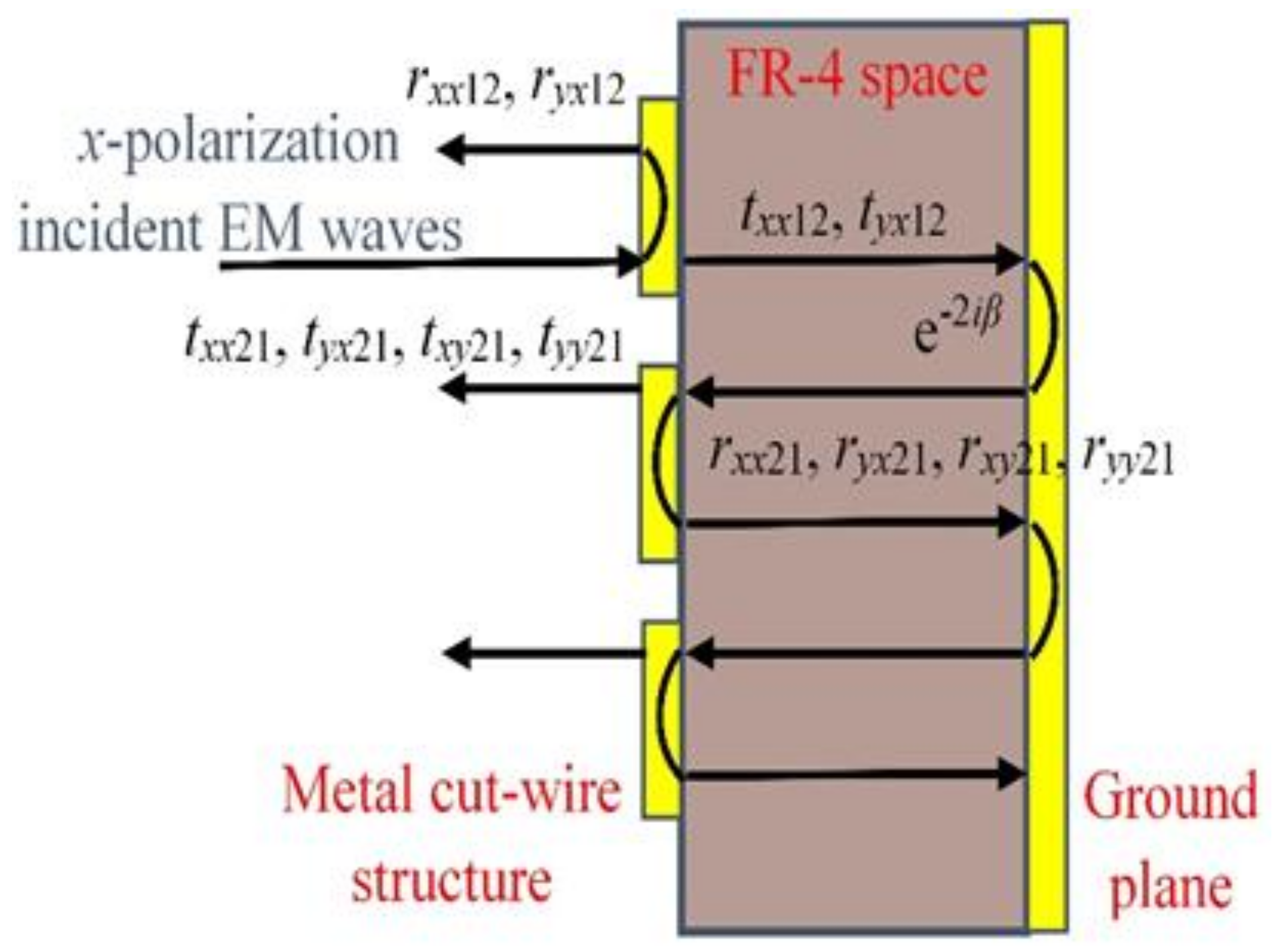
Figure 3.
Simulated, calculated (a) reflection coefficients and (b) PCRs of the designed MS.
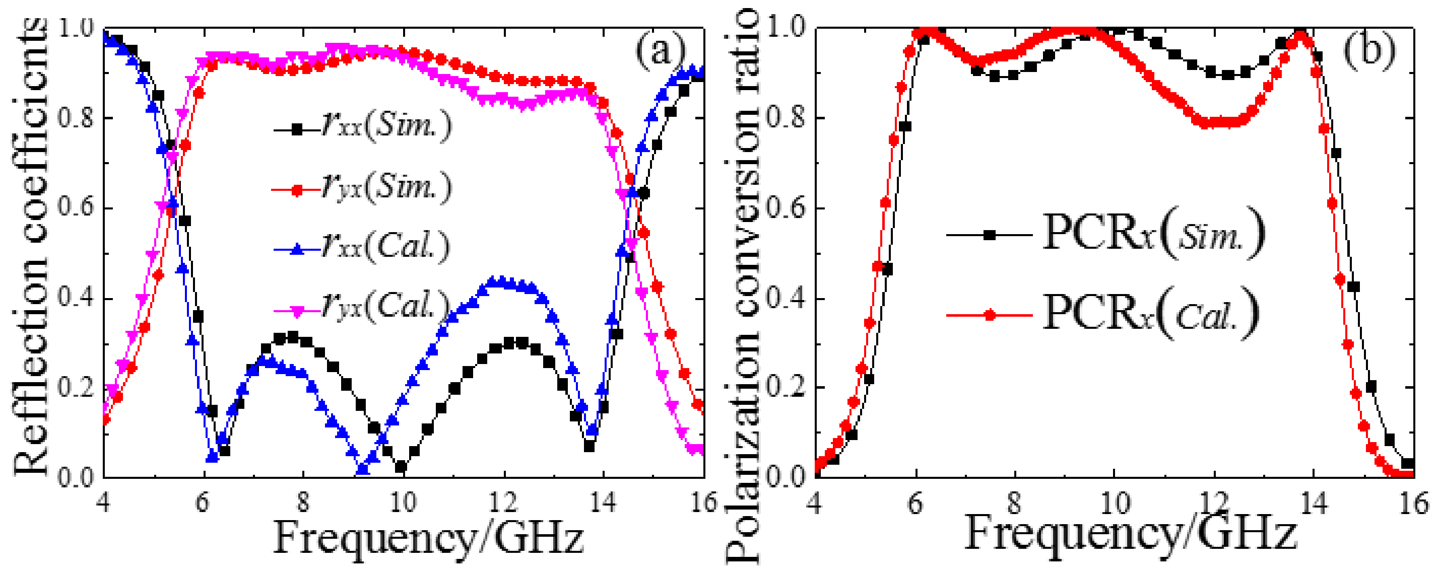
Figure 4.
(a) 2 × 2 structure arrangement of the 01/10 coding MS; (b) illustration of the 01/10 coding MS; the “0” and “1” indicate the super-cells, and are distinguished by blue and yellow colors; each super-cell consists of 5 × 5 unit-cells of “0” and “1”, shown in Figure 1a,b.
Figure 4.
(a) 2 × 2 structure arrangement of the 01/10 coding MS; (b) illustration of the 01/10 coding MS; the “0” and “1” indicate the super-cells, and are distinguished by blue and yellow colors; each super-cell consists of 5 × 5 unit-cells of “0” and “1”, shown in Figure 1a,b.
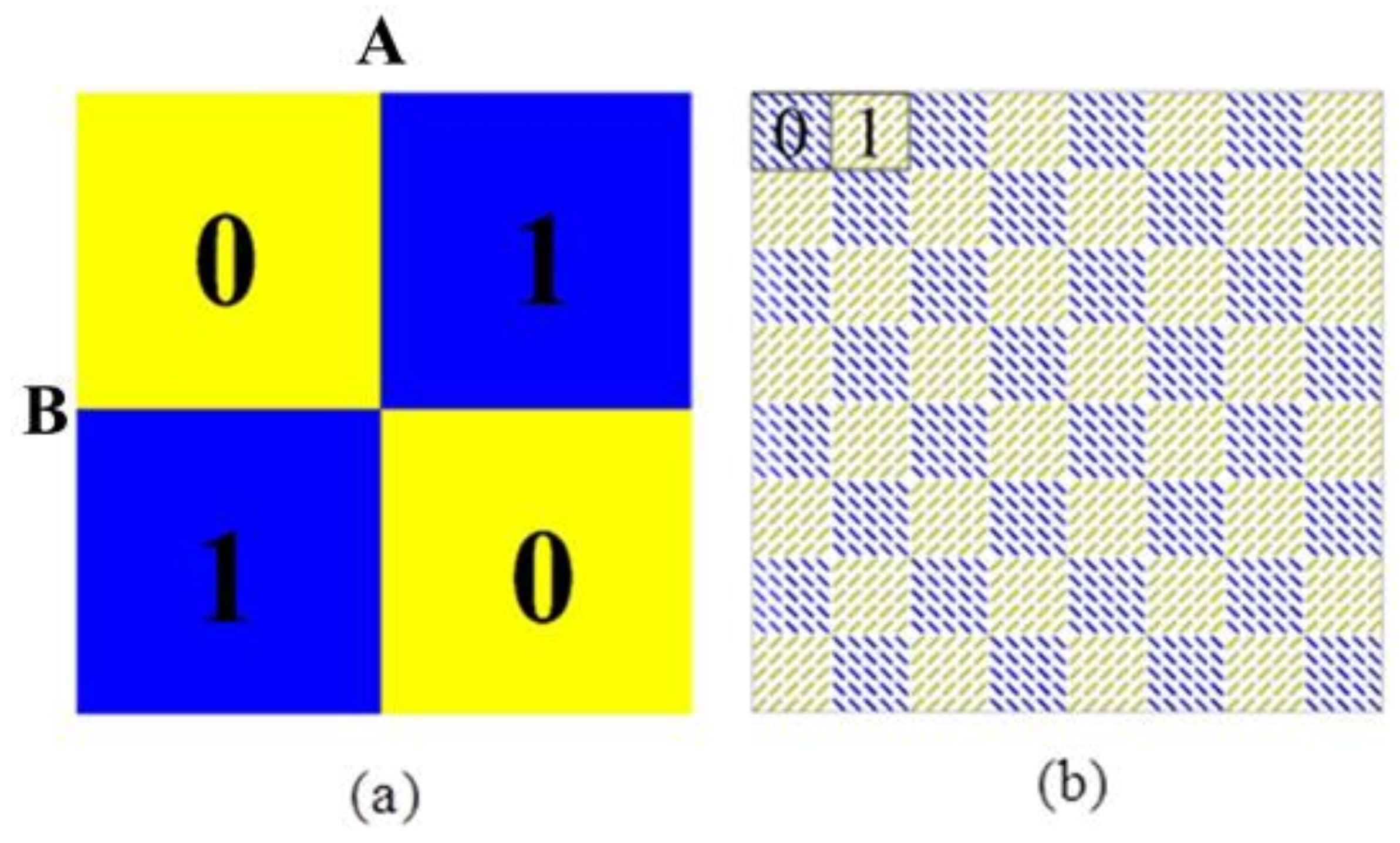
Figure 5.
Simulation far-field patterns of the scattering of (a) 00/00 or 11/11; (b) 01/01 or 10/10; and (c) 01/10 at 10 GHz for the coding MS.
Figure 5.
Simulation far-field patterns of the scattering of (a) 00/00 or 11/11; (b) 01/01 or 10/10; and (c) 01/10 at 10 GHz for the coding MS.

Figure 6.
Simulated results of a series of regular coding MSs: (a) RCS reduction of 01/10 coding MS for different super-cell combinations; (b) RCS reduction of the different regular coding MS with 5 × 5 super-cell; (c) RCS reduction of the 01/01 coding MS for normal x- and y-polarized incident waves; (d) RCS reduction of the 01/10 coding MS for normal incident x- and y-polarized waves.
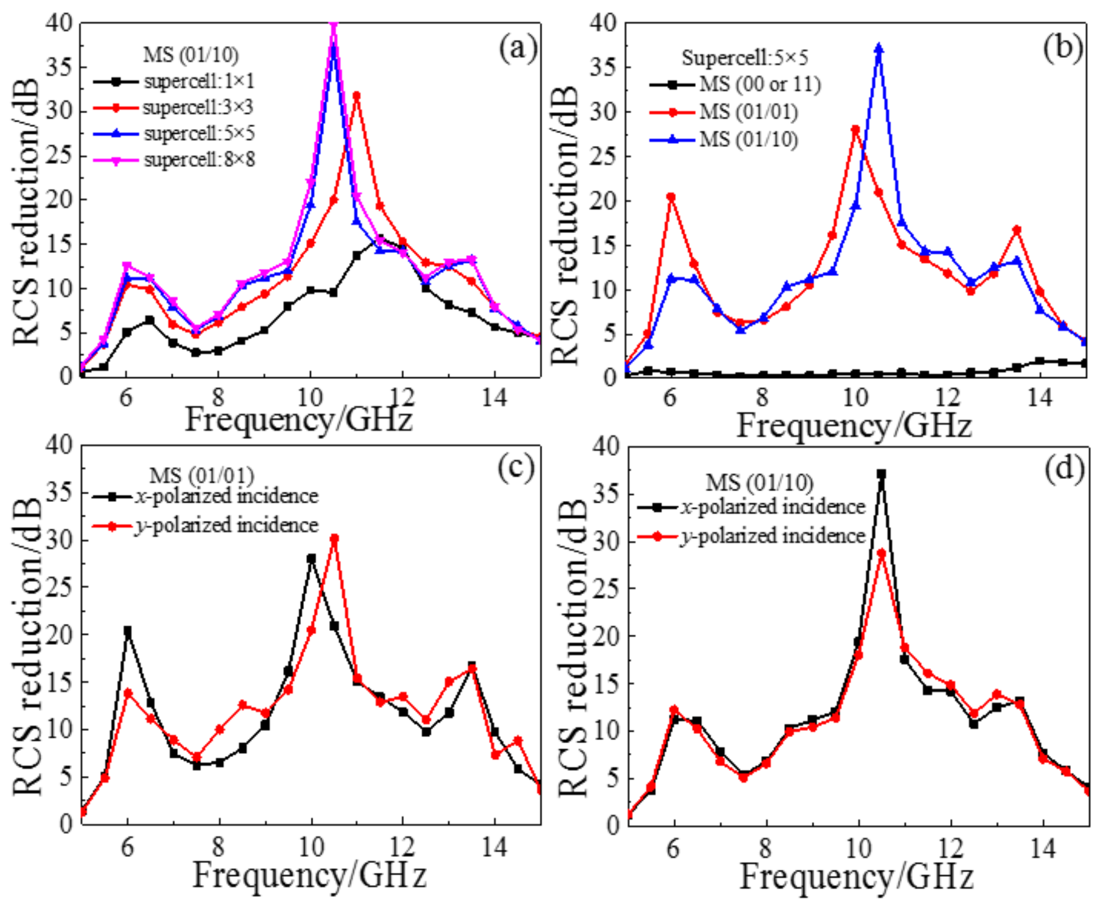
Figure 7.
Scattering patterns of the 01/10 coding MS and metal plate in the XOZ-plane at (a) 6 GHz; (b) 10 GHz; (c) 11 GHz; and (d) 14 GHz.
Figure 7.
Scattering patterns of the 01/10 coding MS and metal plate in the XOZ-plane at (a) 6 GHz; (b) 10 GHz; (c) 11 GHz; and (d) 14 GHz.

Figure 8.
(a) The fabricated 01/10 coding MS sample; (b) the measurement setup in the microwave anechoic chamber.
Figure 8.
(a) The fabricated 01/10 coding MS sample; (b) the measurement setup in the microwave anechoic chamber.
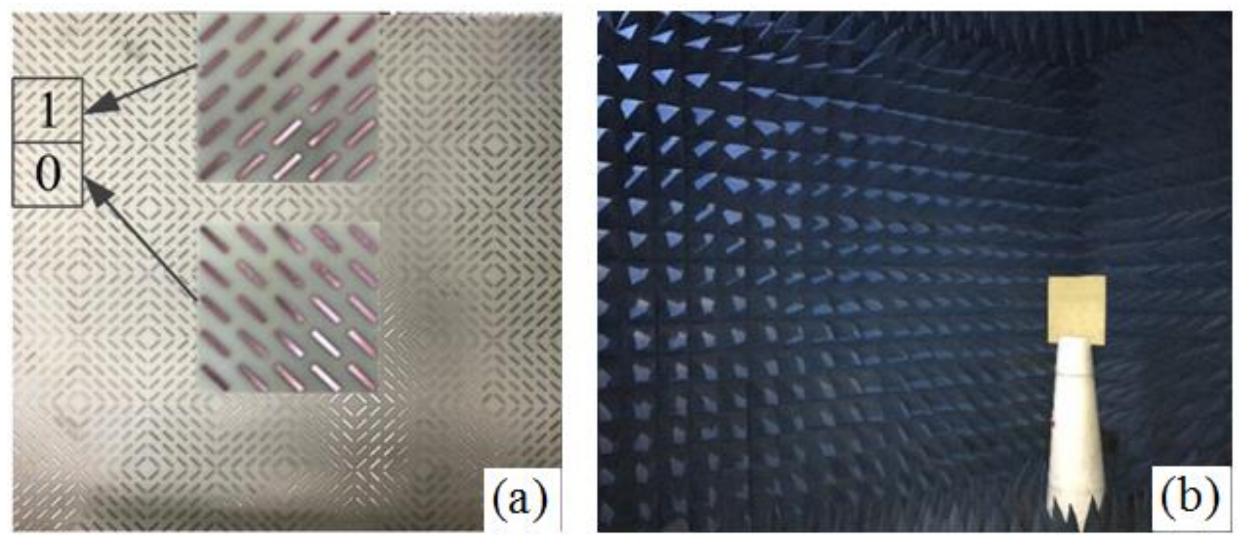
Figure 9.
(a) The simulated and measured reflectance results of the sample; (b) RCS reduction of the sample under oblique incident waves from 0° to 30°.
Figure 9.
(a) The simulated and measured reflectance results of the sample; (b) RCS reduction of the sample under oblique incident waves from 0° to 30°.
© 2018 by the authors. Licensee MDPI, Basel, Switzerland. This article is an open access article distributed under the terms and conditions of the Creative Commons Attribution (CC BY) license (http://creativecommons.org/licenses/by/4.0/).
Share and Cite
MDPI and ACS Style
Yang, J.J.; Cheng, Y.Z.; Ge, C.C.; Gong, R.Z. Broadband Polarization Conversion Metasurface Based on Metal Cut-Wire Structure for Radar Cross Section Reduction. Materials 2018, 11, 626. https://doi.org/10.3390/ma11040626
AMA Style
Yang JJ, Cheng YZ, Ge CC, Gong RZ. Broadband Polarization Conversion Metasurface Based on Metal Cut-Wire Structure for Radar Cross Section Reduction. Materials. 2018; 11(4):626. https://doi.org/10.3390/ma11040626
Chicago/Turabian StyleYang, Jia Ji, Yong Zhi Cheng, Chen Chen Ge, and Rong Zhou Gong. 2018. "Broadband Polarization Conversion Metasurface Based on Metal Cut-Wire Structure for Radar Cross Section Reduction" Materials 11, no. 4: 626. https://doi.org/10.3390/ma11040626
Note that from the first issue of 2016, this journal uses article numbers instead of page numbers. See further details here.