Article

Mechanical Analysis of Ceramic/Polymer Composite with Mesh-Type Lightweight Design Using Binder-Jet 3D Printing

3D Printing Manufacturing Process Center, Korea Institute of Industrial Technology (KITECH), Ulsan 44413, Korea
*
Author to whom correspondence should be addressed.
These authors contributed equally to this work.
Materials 2018, 11(10), 1941; https://doi.org/10.3390/ma11101941
Submission received: 10 September 2018 / Revised: 2 October 2018 / Accepted: 5 October 2018 / Published: 11 October 2018

Abstract

:
3D printing technology has recently been highlighted as an innovative manufacturing process. Among various 3D printing methods, binder jetting (BJ) 3D printing is particularly known as technology used to produce the complex sand mold quickly for a casting process. However, high manufacturing costs, due to its expensive materials, need to be lowered for more industrial applications of 3D printing. In this study, we investigated mechanical properties of sand molds with a lightweight structure for low material consumption and short process time. Our stress analysis using a computational approach, revealed a structural weak point in the mesh-type lightweight design applied to the 3D-printed ceramic/polymer composite.

1. Introduction

A casting process has played an important role in the field of conventional metal technology for thousands of years. As a manufacturing method for various machines, automobiles, ships and their parts, the casting process is still being selected with a high portion: Machine tools (81%), electrical machinery (80.8%), textile machinery (50%), ship machinery (99.2%), and automobiles (13%) [1]. Nowadays, a primary paradigm shift is however occurring from the classical mass production to smaller and customized amounts. This change in manufacturing environment is requiring a faster and more flexible production process such as additive manufacturing.
The additive manufacturing technology called 3D Printing is attracting attention as one of the representative technologies that can lead the 4th Industrial Revolution [2]. In fact, 3D printers are actively applied to various fields of electronics [3], telecommunications [4], biology [5], and industrial construction [6]. Moreover, 3D printed modules and frameworks are used also in many medical fields, such as cardiothoracic surgery [7], orthopedics [8], neurosurgery [9] and dentistry [10]. Actually, 3D printers can be used alone or in combination with 3D radiologic [11] or optical scansion devices [12]. The International Organization for Standardization (ISO)/American Society for Testing and Materials (ASTM) have classified 3D printing technology based on lamination methods into seven categories: Photo polymerization (PP), material extrusion (ME), binder jetting (BJ), material jetting (MJ), direct energy deposition (DED), powder bed fusion (PBF), and sheet lamination (SL) at ISO/ASTM 52900:2015 [13].
Among the various 3D printing techniques, binder-jetting is a method used to bind together powder particles by selectively jetting a polymer binder layer-by-layer to form a green part. Particularly, a sand BJ 3D printer has a large benefit as it makes complicated sand molds directly without a wooden mold, which is necessary in a conventional sand mold process. It is also possible to produce sand molds using BJ 3D printing, which is faster than using the conventional casting method. For example, BJ 3D printing quickly makes sand molds with integrated gating systems, embedded cores, and without the need for a wooden mold [14]. However, the high material and process costs of BJ 3D printing need to be lower for a wide industrial application of 3D printing.
Previous studies [15,16] have focused on evaluating characteristics of the sand molds manufactured by 3D printing in comparison with the conventional method, and on reducing the material consumption in 3D-printed molds with a shell structure. Snelling et al. [17] have adopted BJ 3D printing to produce sand molds with a complex pattern. In a study by Shangguan et al. [18], they fabricated molds with a shell-truss structure using 3D printing, reducing the use of materials by two-thirds compared to conventionally-made molds. In addition, the cooling time of melting aluminum could be successfully controlled by the application of lightweight structures [19]. Deng et al. [20]. who also suggested a new lightweight design of sand molds with the air cavity on riser using a BJ 3D printer, found that solidification time can improve by 12.5% through an insulation effect at the riser cavity.
As mentioned above, only macroscopic designs have been previously studied for the additive manufacturing of sand molds. The macroscopic design for reducing the volume of sand molds depends on their shape. However, a lightweight design with a smaller length scale level, such as a pattern, may be possibly applied regardless of the shape of sand molds, and thus will considerably increase the adaptability of Design for Additive Manufacturing (DfAM) in BJ 3D printing.
In this work, we try to find a methodology of the lightweight design in a smaller length scale for BJ 3D printing, such as a typical conformal lattice cell in metal. To investigate the mechanical properties of lightweight designs, we introduce a basic unit block sample of a ceramic/binder composite applied to a whole sand mold using a BJ 3D printer in this study. The selection of two different structures was just done in this research for the purpose of comparing a typical lightweight design for metal with our ideal structure. We also address geometrical effects, such as the size and shape of typical lightweight patterns provided by commercial DfAM software on the basis of mechanical property evolution.

2. Experimental and Simulation Set-Up

To examine basic design factors of a lightweight structure for a sand/polymer composite, two types of lightweight structures were introduced in this work: a box with square holes (Type-1) and a lattice with upper and bottom pads (Type-2). Type-2 was designed with typical patterns for metals using a commercial topology optimization software (3-matic, ver.12, Materials company in Leuven, Belgium) as shown in Figure 1. Both types of the sample have a cubic dimension of 50 mm. In the mesh type sample, the size of the mesh relatively decreases while the height of the bulk of the top and bottom increases to 6 mm, 8 mm, 10 mm, and 15 mm, and the total height of mesh type sample is fixed to 50 mm.
The lightweight specimens were printed using VSX1000 model (Voxeljet company in Friedberg, Germany), sand BJ 3D printer. For sand BJ 3D printing we adopted the sand (GS19, Strobel Quarzsand company in Freihung, Germany) with a medium grain size of 0.198 mm, and the binder (VX-2C Type B, Voxeljet company in Freiberg, Germany). The thickness of the sand layer was about 300 μm during the printing process. The binder-type was furan resin, which chemically reacted as cold hardening with the activator coated at sand surface.
The compression test which was based on a conventional method, following the procedures of Korean Standard (KS A 5301:1995) and the American Foundry Society [21] has been modified by placing samples between circular steel plates [22,23,24] in this work. Our lightweight-designed samples are evaluated using a universal testing machine (KDMT-156, Kyung Do Precision Co., Ltd., in Kyungi-do, Republic of Korea). The compression test was carried out at a rate of 1.2 mm/min under a load of 10 tons [25,26,27]. Each test was conducted twice for data accuracy. The test samples were broken by initiation of cracks, and no creep behavior was observed during testing.
We also conducted computational analysis with the conditions shown in Table 1, in order to predict stress distribution and fracture under uniaxial-loading. To reveal the correlation of lightweight degree and strength, the volume ratio (ρ/ρ0) is particularly defined as the lightweight-designed volume (ρ) divided by the initial cubic volume (ρ0) in this study. In this work, all graphs were plotted by Microsoft Excel software (Redmond, DC, USA). COMSOL Multiphysics software (ver.5.2, Burlington, MA, USA) also was used for computational analysis. No data analysis has been performed as each test was conducted twice for data accuracy. Tests have been conducted only two times as the difference between the two measures has been recorded to be very low.

3. Results and Discussion

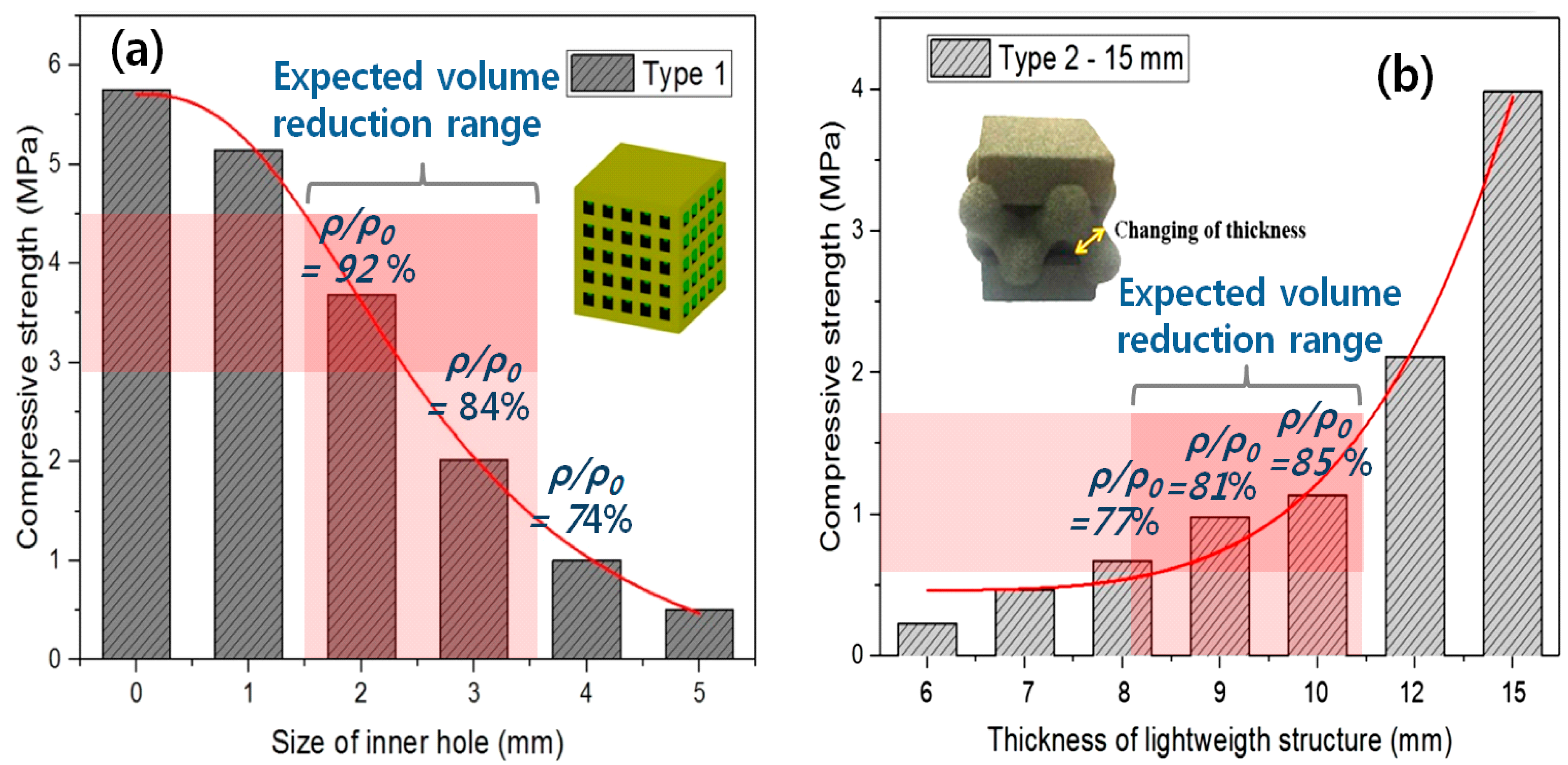
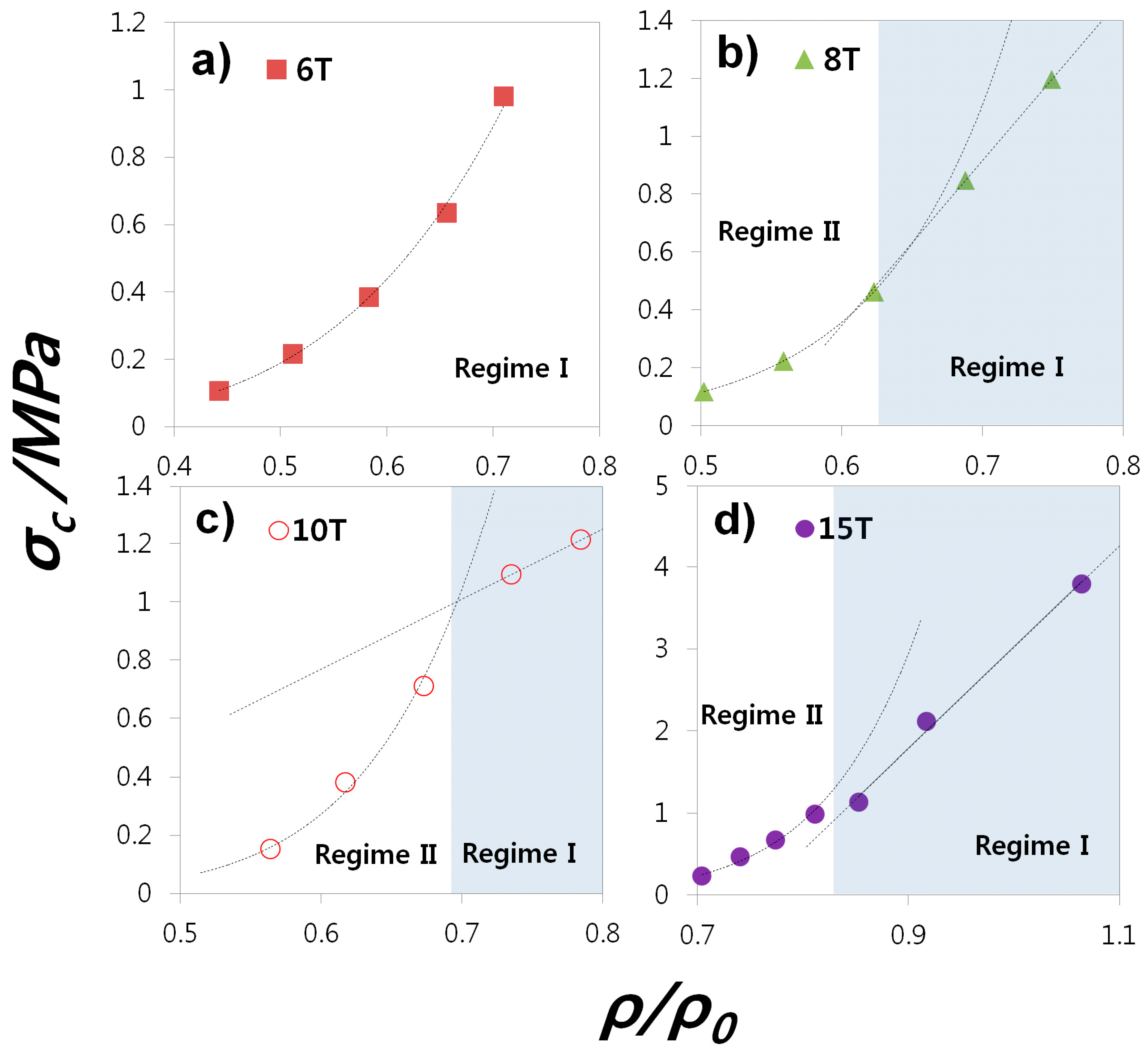
3.1. Lightweight Designs and Strength

To obtain an optimum lightweight pattern design for a ceramic/polymer composite using the BJ 3D printing technique, it is necessary to consider two competing factors: Structural strength and ease of taking out unbound sand powders. Normally, lightweight designs decrease the total weight by regularly arranging an empty space inside a structure. While an excessive hollow volume inside the ceramic/polymer composite results in severe strength drop, a low unfilled one can prevent the unbound sand particles from getting out from the inside of vacant units perfectly. It is thus significant to address the relation between strength and hollow volume density considering the taking-out of unbound sand powders.
For the purpose of controlling the hollow volume density in this work, we introduce two types of geometrical unit patterns: reducing total volume by arraying square holes and increasing the total one by increasing lattice beam thickness (see small sample images of Figure 2). The compressive strength (σC) curves of two lightweight designs are shown in Figure 2.
Figure 2a is a graph of compressive strength (σC) of the sand mold specimen with square holes as a function of size of the square holes. In the case of the specimen with 1 mm inner hole, it is difficult to remove the inner unbound sand powders. It turns out the size of the inner hole should be at least 2 mm to take out the inner sand powders clearly. σC and ρ/ρ0 decrease as the square hole size increases. A bulk volume with no holes indicates that the inner hole size is zero in Figure 2a. The σC value, ~5.7 MPa, of the bulk volume decreases to ~20% of the initial one, with the hole size of 4 mm corresponding to a ρ/ρ0 of 74%.
Figure 3b shows the σC with a change in the lattice beam thickness in Type-2. To avoid an abnormal and easy fracture at the top and bottom of lattice structures interfacing with a tester during a uniaxial compression test, a solid volume, acting as a pad, with a 15-mm thickness (15T) is added to the top and bottom faces of the samples, respectively [28,29]. Basically, σC increases as the lattice beam thickness increases. Additionally, σC values increase more largely in high density samples (12T and 15T of Figure 2b) with a lattice-type (Type-2), compared with those of the hole-type samples (Type-1) in Figure 2a. Adopting a thin lattice beam thickness normally applied to a metal lightweight design on our sand mold structure, some samples with thick lattice thickness have an exaggerated mesh shape (see the sample image of Figure 2b) which exceeds the boundary of the original bulk volume. This may cause a large increase in the σC of thick lattice samples (12~15 mm) (Figure 2b). Although Type-1 has higher strength, it is more difficult than Type-2, to take-out sand particles from samples. Hence, our further studies will focus on enhancing the low strength of Type-2.

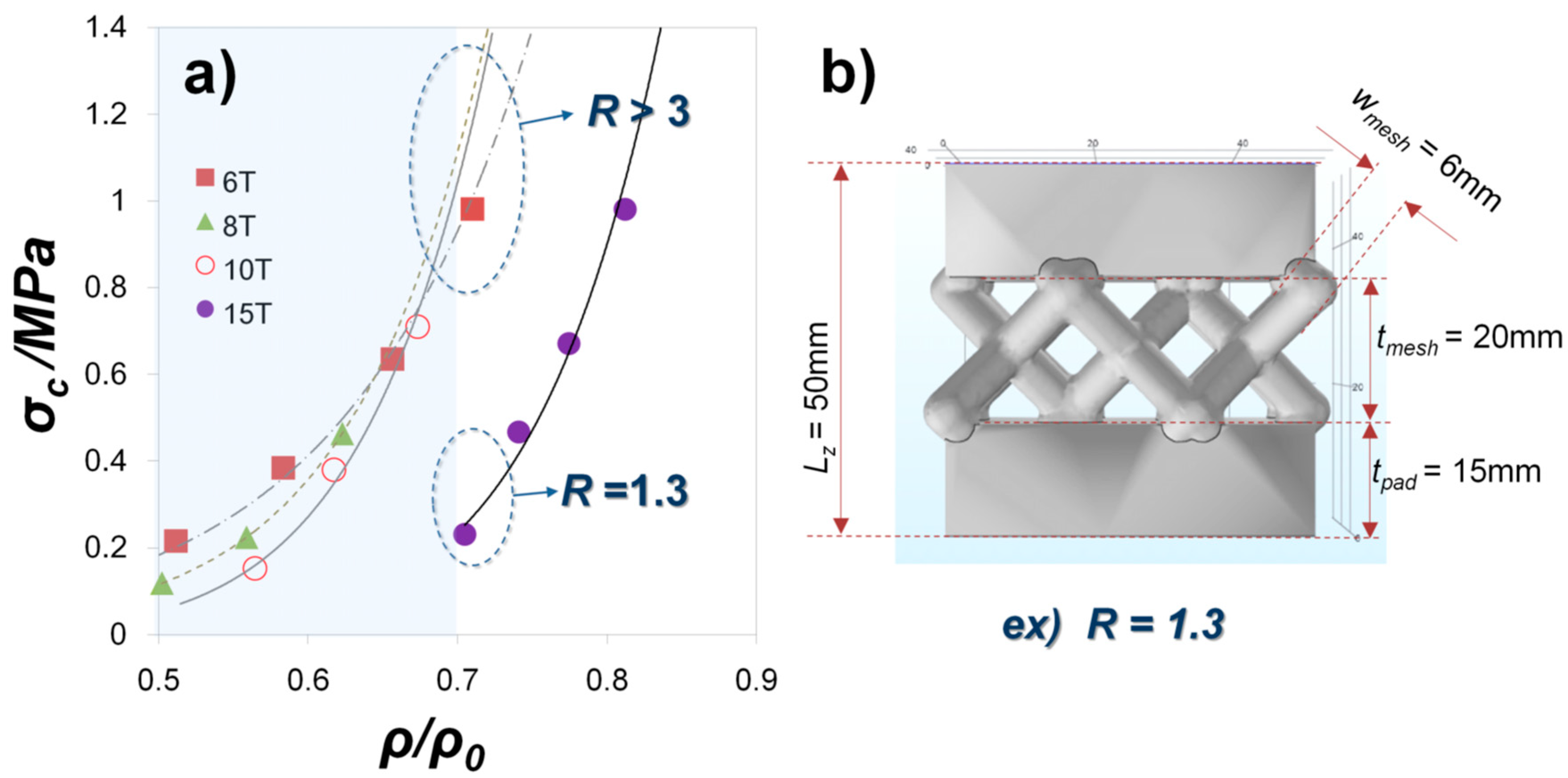
3.2. Design Factors of Mesh-Type Lightweight Structure
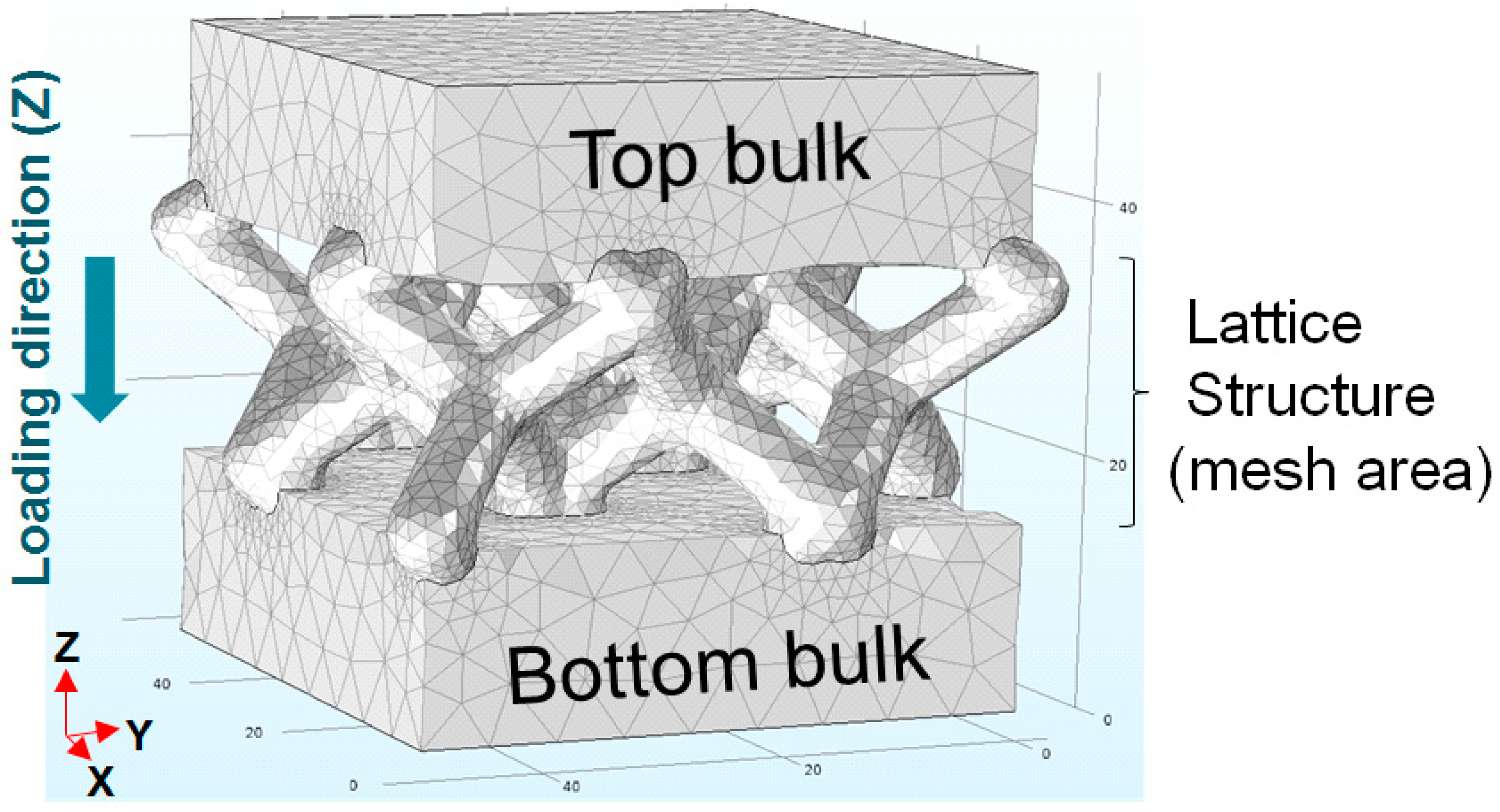
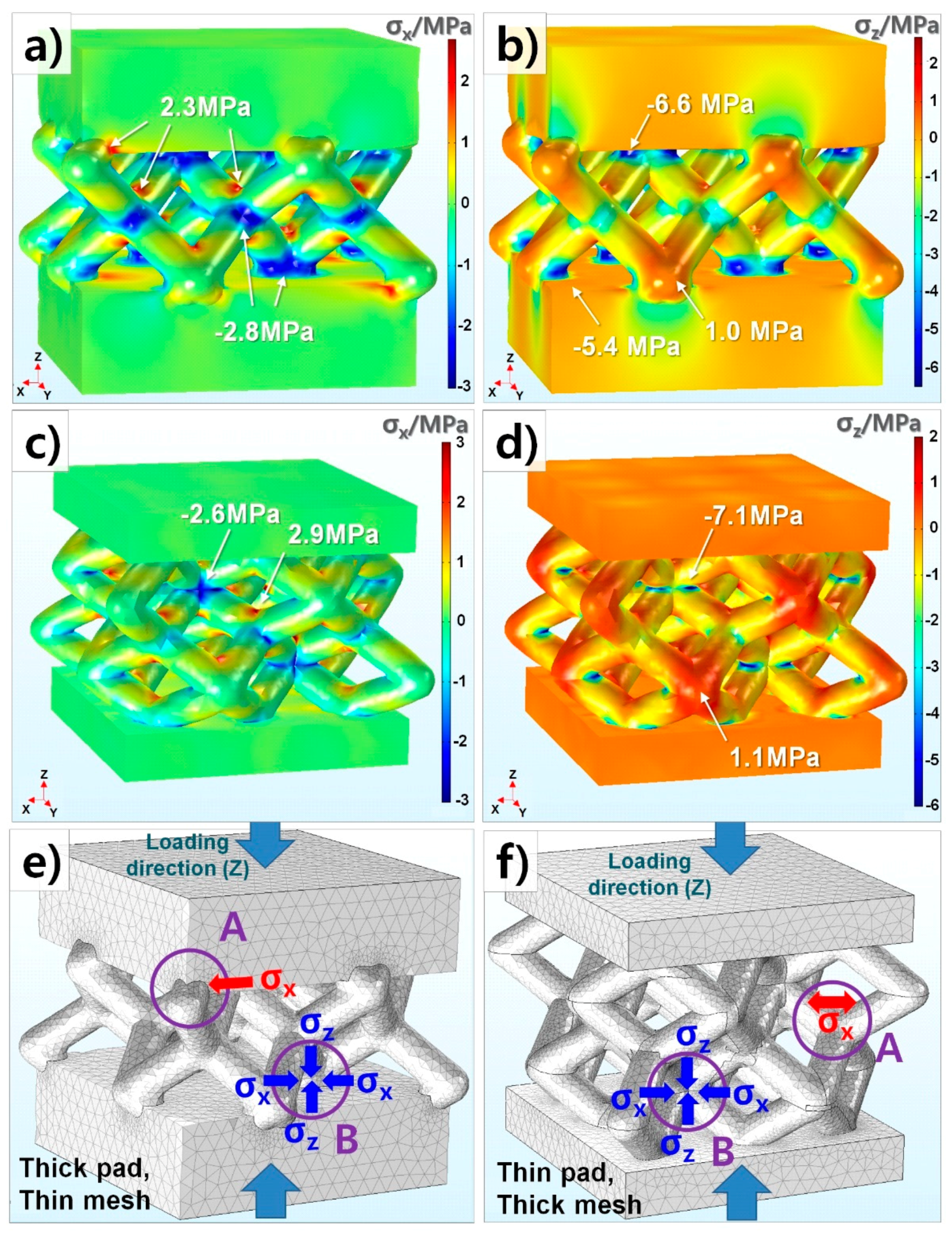
Dependence on the strength of our lightweight structures for the thickness of mesh beams and pads as design factors is investigated in this chapter. Figure 3 shows a change of σC by ρ/ρ0. In the case of pad thickness > 8 (8 T, 10 T, and 15 T), the relation between σC and ρ/ρ0 appears to be linearly proportional and exponential at high and low ρ/ρ0, respectively. As the pad size of our mesh-type structure decreases, a transition from dual (Regime-II) to single (Regime-I) correlation takes place. The single plot of σC-ρ/ρ0 at whole ρ/ρ0 range is a reasonable mechanical response of a pure mesh-structure. The exponential curve of 6 T shown in Figure 3a is thus considered typical behavior of the mesh-type ceramic/polymer composite. On the other hand, the linear plot of σC-ρ/ρ0 which appears from Figure 3b–d seems to be a mechanical response of bulk rather than mesh since observed with a thick pad thickness (>8 T) and a high ρ/ρ0 (Regime II). This behavior is defined as ‘pseudo-bulk’ in this work. The pseudo-bulk is not real solid bulk, but it is still a mesh-type bulk. It is suggested that its different mechanical response, less sensitive strength drop with decreasing ρ/ρ0, may be caused because the local stress concentration, which results in a fracture, is lower than in mesh-type structures with low ρ/ρ0. Thin mesh beam structures are, hence, more fragile.
We also examine compressive strength by a relative portion of pad and mesh at our mesh-type sample as shown in Figure 4a. The mesh-type sample has a vertical length (lz) of 50 mm in Figure 4b. Since the samples consist of top and bottom mesh and pads, the thickness of both pad (tpad) and mesh (tmesh) portions can vary in relation to 2 × tpad + tmesh = lz. The pad thickness is changed from 6 mm to 15 mm, which results in a different pad-mesh ratio (R = tmesh/tpad) and volume ratio (ρ/ρ0). As ρ/ρ0 decreases by applying the lightweight mesh-type structure, σC gradually decreases in all samples with a pad thickness of 6 mm, 8 mm, 10 mm, and 15 mm (6 T, 8 T, 10 T, and 15 T). When ρ/ρ0 is close to 0.7, the σC value at 15 T is much lower than those at 6 T, 8 T and 10 T. Whereas the R value of 15 T sample is 1.3 at ρ/ρ0 = 0.7, all other samples which show higher σC values satisfy ‘R > 3’. Therefore, it turns out that thick pads in a mesh-type lightweight structure seriously decrease in strength. The present report is very unique in its study of the relation between mechanical analysis and structural design in the ceramic 3D printing as no other studies have evaluated this specific topic.

3.3. FEM Analysis

To analyze the effect of structural factors on mechanical fracture in detail, FEM simulation is introduced in this study. In view of stress to x and z-direction (σx and σz), the mesh-type sample with tpad = 15 mm and tmesh = 6 mm which was seen to be particularly low σC (0.23 MPa) at ρ/ρ0 = 0.7 (Figure 4) is compared with that of tpad = 8 mm and tmesh = 10 mm (σC = 1.19 MPa), as depicted in Figure 5. Figure 5 illustrates the mechanical stress distribution of two samples with 15T-6 mm (tpad-mesh) (Figure 5a,b) with 8 T-10 mm (tpad-tmesh) (Figure 5c,d). Since our mesh samples show 4-fold symmetry at the z-axis, σx and σy should be almost the same. σx distribution is thus seen without σy. The stress concentration mainly occurs at the mesh areas of both samples. As observed in Figure 5a–d, the samples 15 T-6 mm and 8 T-10 mm do not show any big stress differences which enable much lower σC of the former. While the sample with 15 T-6 mm gets higher tensile and compressive stress concentration (A,B) at the mesh and pads interface in Figure 5e, the one with 8 T-10 mm does at internal mesh structure in Figure 5f. It is expected that easy cracks are initiated at a comparatively weak boundary between the mesh and pads of 15 T-6 mm.

4. Conclusions

In this work, we studied fundamental design factors of lightweight structures for a BJ 3D printer and carried out those mechanical evaluations using experiments and FEM simulations.
(1)
Compressive strength was measured with two lightweight designs, a cube with square holes (Type-1), a mesh structure with pads (Type-2), and the strength of both which remarkably decrease with the increasing volume ratio (ρ/ρ0). It turns out that the size of the inner hole of the Type-1 sample should be at least 2 mm for taking out the inner sand powders clearly. Although Type-1 has higher strength, it is more difficult than Type-2 to take out sand particles from samples. Hence, our further study will focus on enhancing the low strength of Type-2.
(2)
With mesh-type lightweight structures, increasing pad thickness and decreasing a mesh area results in increasing the local stress concentration at the interface of the mesh and pads. It is expected that easy crack is initiated at a comparatively weak boundary between mesh and pads in the case of thick pad thickness.
(3)
Since a commercial software for topology optimization provides lightweight designs for rigid single component materials such metals or plastics, it is not suitable to apply the lightweight designs to a ceramic/polymer composite with different mechanical behaviors. As a result, new types of light weight structures for sand casting molds are required to spread BJ 3D printing technology to the foundry industry.
(4)
Further study will suggest and evaluate the new lightweight and rigid design of for additive manufacturing of a ceramic/polymer composite. It will reveal the correlation between structural and mechanical factors of the lightweight designs in detail.

Author Contributions

Conceptualization, D.-H.K. and J.L.; Methodology, D.-H.K. and J.L.; Software, D.-H.K. and J.L.; Validation, E.K., S.P. and J.C.; Formal Analysis, D.-H.K. and J.L.; Investigation, J.B.; Resources, S.P. and J.C.; Data Curation, J.L. and J.B.; Writing-Original Draft Preparation, D.-H.K. and J.L.; Writing-Review & Editing, D.-H.K., J.H.L. and J.L.; Visualization, D.-H.K. and J.L.; Supervision, D.-H.K.; Project Administration, E.K.; Funding Acquisition, E.K.

Funding

This material is based upon work supported by the Ministry of Trade, Industry & Energy (MOTIE, Korea) under Industrial Technology Innovation Program (Grant No. KM180091). This work is also supported by Seed Research Fund (Grant No. UR170045) at KITECH.

Conflicts of Interest

The authors declare no conflict of interest.

References

  1. Gunther, D.; Mogele, F. Additive Manufacturing of Casting Tools Using Powder-Binder- Jetting Technology. New Trends 3D Print. 2016, 53–86. [Google Scholar] [CrossRef]
  2. Byun, K.Y.; Lee, C.W.; Kim, K.H.; Kim, H.K.; Lee, B.S. Trend of metal 3D printing design technology. JKEES 2016, 43, 15–22. [Google Scholar]
  3. Butt, J.; Onimowo, D.A.; Gohrabian, M.; Sharma, T.; Shirvani, H. A desktop 3D printer with dual extruders to produce customised electronic circuitry. Front. Mech. Eng. 2018, 13, 528–534. [Google Scholar] [CrossRef]
  4. Jo, E.; Kim, D. 3D Printer Based Lens Design Method for Integrated Lens Antennas. IEEE Antenn. Wirel. PR 2018, 99. [Google Scholar] [CrossRef]
  5. Schmieden, D.T.; BasaloVázquez, S.J.; Sangüesa, H.; Idema, T.; Meyer, A.S. Printing of Patterned, Engineered E. coli Biofilms with a Low-Cost 3D Printer. ACS Synth. Biol. 2018, 7, 1328–1337. [Google Scholar] [CrossRef] [PubMed]
  6. Fathanuary, H.; Yamin, M. Design and modelling of RC aircraft in racing plane category using 3-dimension printer with polylactic acid material. Int. J. Mech. Eng. Tech. 2018, 9, 470–477. [Google Scholar]
  7. Daemen, J.; Heuts, S.; Olsthoorn, J.; Maessen, J.; Nia, P.S. Mitral valve modelling and three-dimensional printing for planning and simulation of mitral valve repair. Eur. J. Cardiothorac Surg. 2018, ezy306. [Google Scholar] [CrossRef] [PubMed]
  8. Southerden, P.; Barnes, D.M. Caudal mandibular fracture repair using three-dimensional printing, presurgical plate contouring and a preformed template to aid anatomical fracture reduction. JFMS Open Rep. 2018, 5, 2055116918798875. [Google Scholar] [CrossRef] [PubMed]
  9. Pucci, J.U.; Christophe, B.R.; Sisti, J.A.; Connolly, E.S., Jr. Three-dimensional printing: Technologies, applications, and limitations in neurosurgery. Biotechnol. Adv. 2017, 35, 521–529. [Google Scholar] [CrossRef] [PubMed]
  10. Kamio, T.; Hayashi, K.; Onda, T.; Takaki, T.; Shibahara, T.; Yakushiji, T.; Shibui, T.; Kato, H. Utilizing a low-cost desktop 3D printer to develop a “one-stop 3D printing lab” for oral and maxillofacial surgery and dentistry fields. 3D Print Med. 2018, 13, 6. [Google Scholar] [CrossRef] [PubMed]
  11. Shelmerdine, S.C.; Simcock, I.C.; Hutchinson, J.C.; Aughwane, R.; Melbourne, A.; Nikitichev, D.I.; Ong, J.L.; Borghi, A.; Cole, G.; Kingham, E.; et al. 3D printing from microfocus computed tomography (micro-CT) in human specimens: Education and future implications. Br. J. Radiol. 2018, 91. [Google Scholar] [CrossRef] [PubMed]
  12. Sfondrini, M.F.; Gandini, P.; Malfatto, M.; Di Corato, F.; Trovati, F.; Scribante, A. Computerized Casts for Orthodontic Purpose Using Powder-Free Intraoral Scanners: Accuracy, Execution Time, and Patient Feedback. BioMed Res. Int. 2018, 2018, 4103232. [Google Scholar] [CrossRef] [PubMed]
  13. ISO/ASTM 52900:2015(en). Available online: https://www.iso.org/obp/ui/#iso:std:iso-astm:52900:ed-1:v1:en (accessed on 3 September 2018).
  14. Kumar, A.; Bai, Y.; Eklund, A.; Williams, C. Effect of Hot Isostatic Pressing on Copper Parts Fabricated via Binder Jetting. Procedia Manuf. 2017, 10, 935–944. [Google Scholar] [CrossRef]
  15. Hawaldar, N.; Zhang, J. A comparative study of fabrication of sand casting mold using additive manufacturing and conventional process. Int. J. Adv. Manuf. Tehcnol. 2018, 97, 1037–1045. [Google Scholar] [CrossRef]
  16. Upadhyay, M.; Sivarupan, T.; Mansori, M.E. 3D printing for rapid sand casting—A review. J. Manuf. Processes 2017, 29, 211–220. [Google Scholar] [CrossRef]
  17. Snelling, D.; Qian, L.; Meisel, N.; William, C.; Batra, R.; Druschitz, A. Lightweight Metal Cellular Structures Fabricated via 3D Printing of Sand Cast Molds. Adv. Eng. Mater. 2015, 17, 923–932. [Google Scholar] [CrossRef]
  18. Shangguan, H.; Kang, J.; Deng, C.; Hu, Y.; Huang, T. 3D-printed shell-truss sand mold for aluminum casting. J. Mater. Process. Tech. 2017, 250, 247–253. [Google Scholar] [CrossRef]
  19. Shangguan, H.; Kang, J.; Yi, J.; Zhang, X.; Wang, X.; Wang, H.; Huang, T. The design of 3D-printed lattice-reinforced thickness-varying shell molds for castings. Materials 2018, 11, 535. [Google Scholar] [CrossRef] [PubMed]
  20. Deng, C.Y.; Kang, J.W.; Shangguan, H.L.; Huang, T.; Zhang, X.P.; Hu, Y.Y.; Huang, T.Y. Insulation effect of air cavity in sand mold using 3D printing technology. China Foundry 2018, 15, 37–43. [Google Scholar] [CrossRef]
  21. American Foundry Society. Mold & Core Test Hand Book; American Foundry Society: Schaumburg, IL, USA, 2006. [Google Scholar]
  22. Mahasneh, B.; Shawabkeh, R. Compressive strength and permeability of sand-cement-clay composite and application for heavy metals stabilization. Am. J. Appl. Sci. 2004, 1, 1–4. [Google Scholar]
  23. McKenna, N.; Singamneni, S.; Diegel, O.; Singh, D.; Neitzert, T.; George, J.; Choudhury, A.R.; Yarlagadda, P. Direct metal casting through 3D printing: A critical analysis of the mould characteristics. In Proceedings of the 9th Global Congress on Manufacturing and Management, Gold Coast, Australia, 12–14 November 2008; pp. 1–5. [Google Scholar]
  24. Feng, P.; Meng, X.; Chen, J.; Ye, L. Mechanical properties of structures 3D printed with cementitious powders. Constr. Build. Mater. 2015, 93, 486–497. [Google Scholar] [CrossRef] [Green Version]
  25. Gökçe, B.; Serdar Çötert, H.; Özcan, M. A study of compressive strength between zirconia framework and veneering ceramic as a function of thermal expansion coefficient using Shell–Nielsen test method. J. Adhesion Sci. Technol. 2015, 29, 1924–1936. [Google Scholar] [CrossRef] [Green Version]
  26. Felipe, A.F.; Miranda Coimbra, W.H.; Pinheiro Carvalho, G.A.; Kreve, S.; Gonçalves Franco, A.B.; Dias, S.C. Evaluation of the bonding strength between yttrium-stabilized zirconia and coating ceramics with three-point flexural Test: The surface treatment effect. Eur. J. Gen. Dent. 2018, 7, 14–18. [Google Scholar]
  27. Seuba, J.; Deville, S.; Guizard, C.; Stevenson, A.J. Mechanical properties and failure behavior of unidirectional porous ceramics. Sci. Rep. 2016, 6, 24326. [Google Scholar] [CrossRef] [PubMed] [Green Version]
  28. Yang, C.; Vora, H.D.; Chang, Y. Behavior of auxetic structures under compression and impact forces. VTT SYMP 2018, 27, 202512. [Google Scholar] [CrossRef]
  29. Smith, M.; Cantwell, W.J.; Guan, Z.; Tsopanos, S.; Theobald, M.D.; Nurick, G.N.; Langdon, G.S. The quasi-static and blast response of steel lattice structures. J. Sandwich Struct. Mater. 2011, 13, 479–501. [Google Scholar] [CrossRef]
Figure 1. The image of a mesh-type sample having a lattice structure and solid bulk pads at the top and bottom.
Materials 11 01941 g001
Figure 2. Change of compressive strength (σC) by (a)-hole size and (b)-lattice beam thickness at two different types of samples: Type-1—cube with square holes, Type-2—mesh structure with pads. The definition of volume ratio (ρ/ρ0) was previously mentioned in the chapter of ‘experimental and simulation set-up’. In Type-2, each sample according to its pad thickness is called T (e.g., 12 mm →12 T).
Materials 11 01941 g002
Figure 3. Various compressive strength (σC) plot as a function of volume ratio (ρ/ρ0) at different pad (bulk) thickness (tpad = (a) 6 T, (b) 8 T, (c) 10 T and (d) 15 T).
Materials 11 01941 g003
Figure 4. (a)-Compressive strength (σC) as a function of volume ratio (ρ/ρ0) with different pad (bulk) thickness (tpad = 6 T, 8 T, 10 T and 15 T) and (b)-thickness ratio of mesh and bulk (R = tmesh/tpad).
Materials 11 01941 g004
Figure 5. Mechanical stress analysis of lightweight designs with 15T-6 mm and 8T-10 mm (pad thickness and mesh beam width). (a) σx distribution (x-direction stress) of 15T-6 mm (b) σz distribution (z-direction stress) of 15T-6 mm (c) σx distribution of 8T-10 mm (d) σz distribution of 8T-10 mm (e) Stress concentration of 15T-6 mm (tpad > tmesh), A and B: Tensile and compressive stress at the interface of the mesh and pads, respectively (f) Stress concentration of 8T-10 mm (tpad < tmesh), A and B: Tensile and compressive stresses at internal mesh structure, respectively.
Materials 11 01941 g005
Table 1. Analytical methods and conditions used in computer numerical analysis.
SoftwareCompression with Prescribed VelocityLoading DirectionCompression TimeMechanical Analysis
COMSOL Multiphysics®−2 × 10⁻⁵ m/sZ-direction0.1 sUsing principal stress (σXX, σYY, σZZ)

