Effect of Molten Pool Size on Microstructure and Tensile Properties of Wire Arc Additive Manufacturing of Ti-6Al-4V Alloy

Abstract
:1. Introduction
2. Experimental Procedures
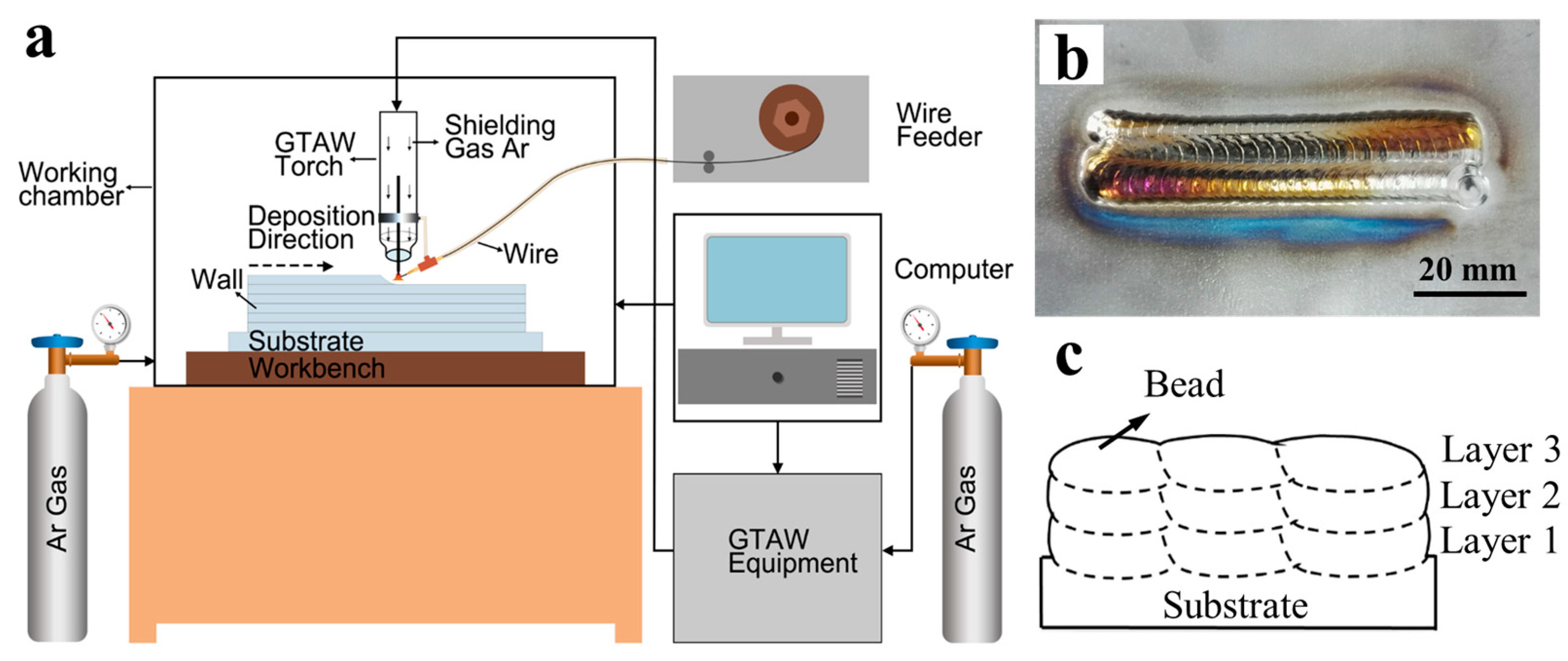
2.1. Experimental Setup and Manufacturing Process
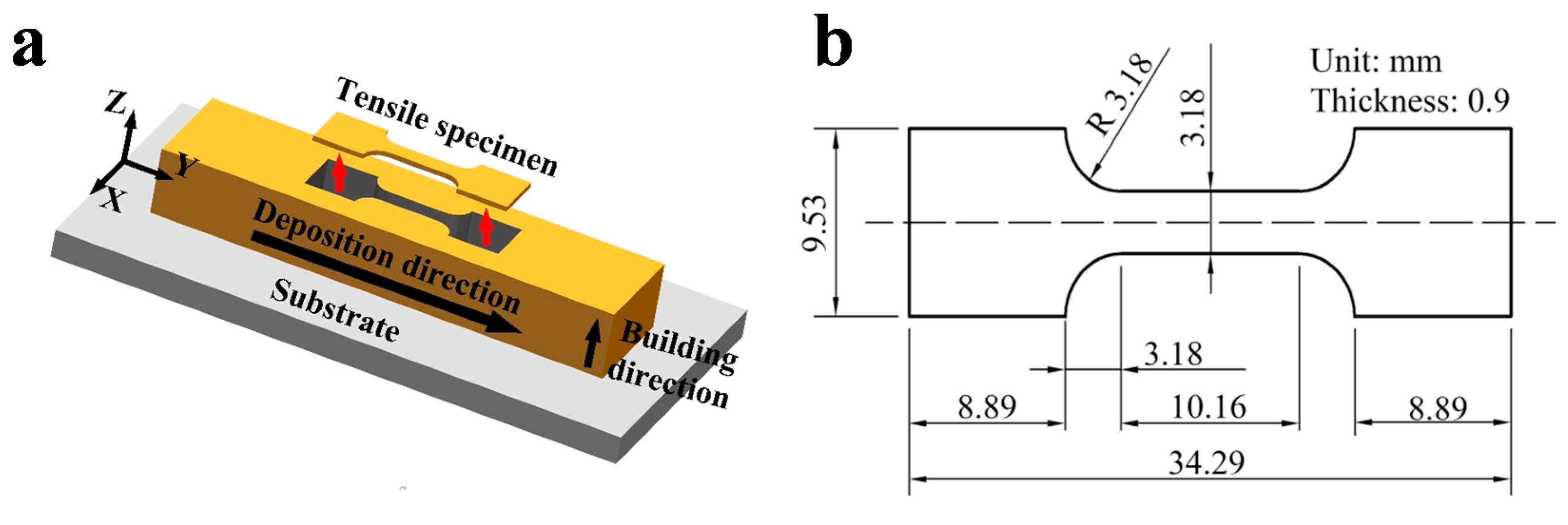
2.2. Characterization
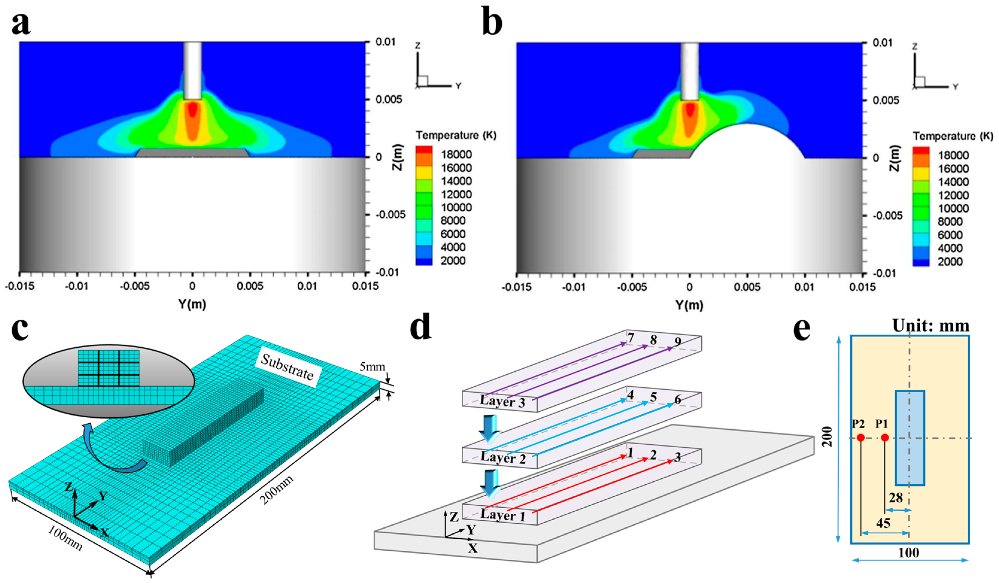
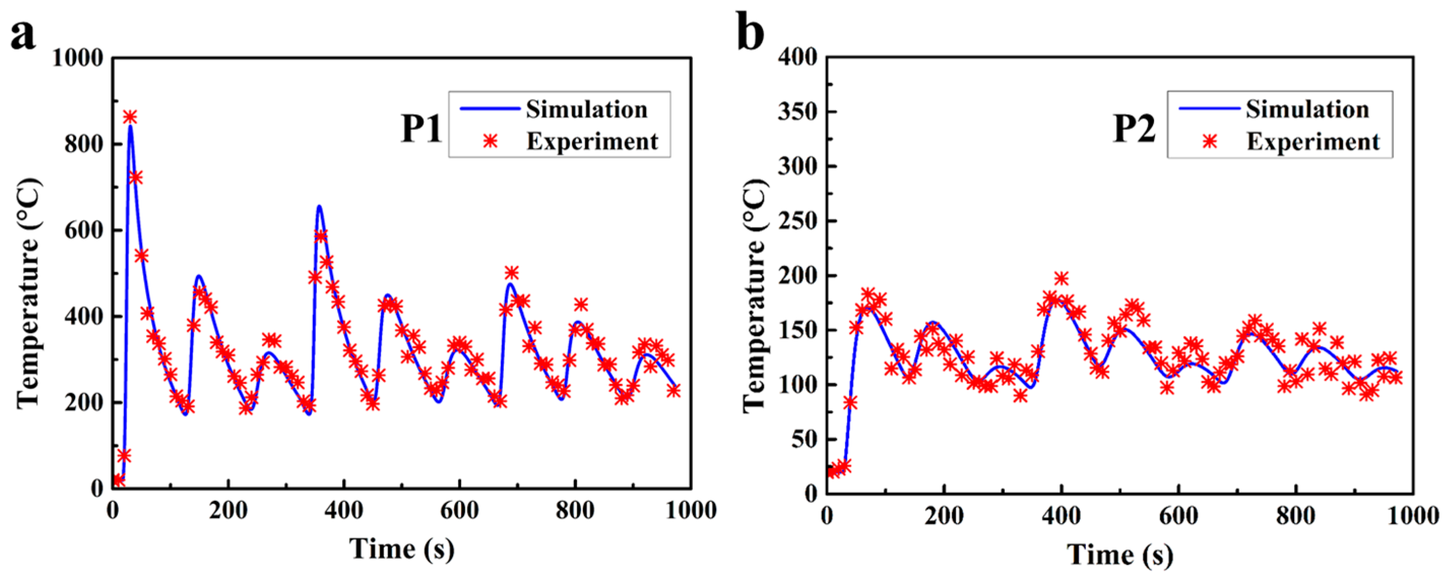
2.3. Modeling
3. Results and Discussion
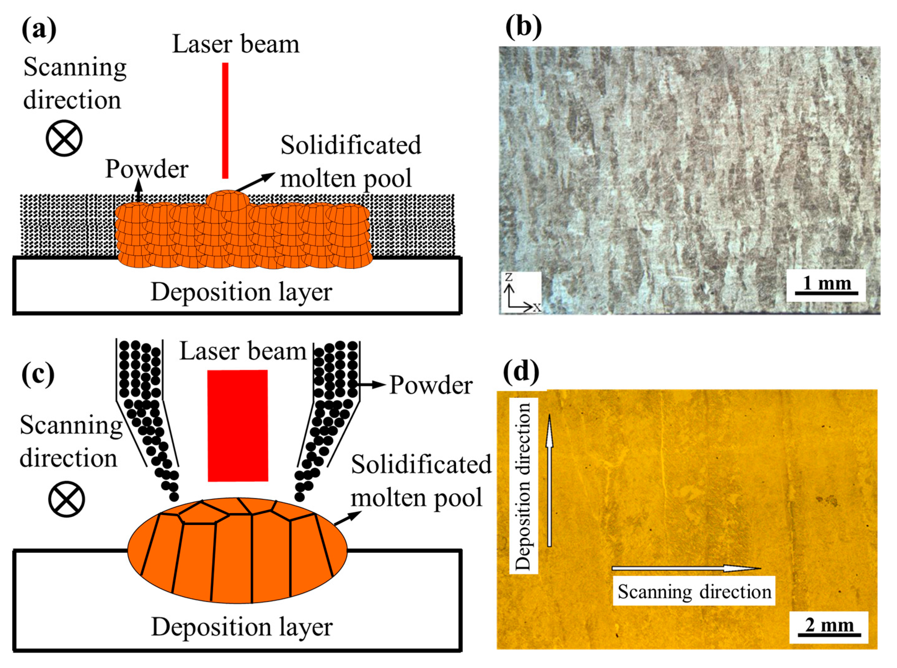
3.1. Macrostructure
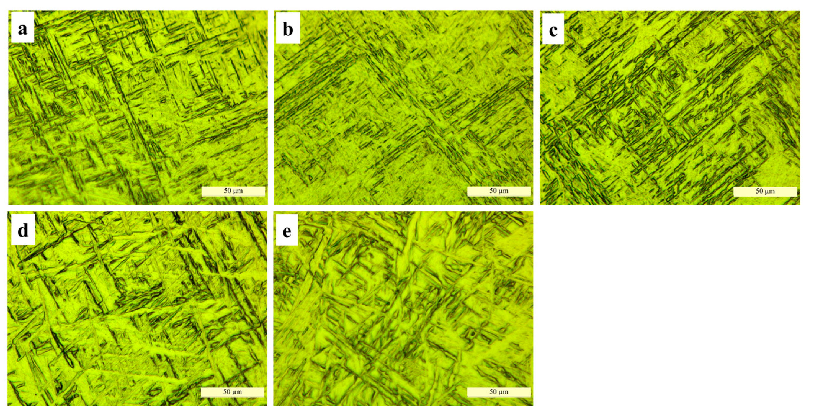
3.2. Microstructure
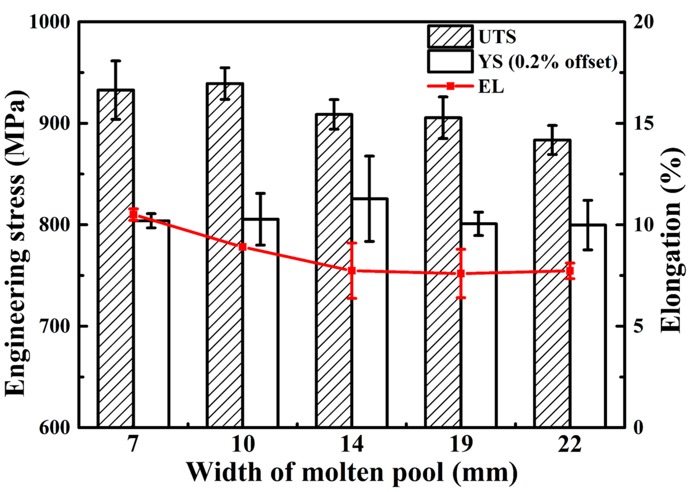
3.3. Tensile Properties
4. Conclusions
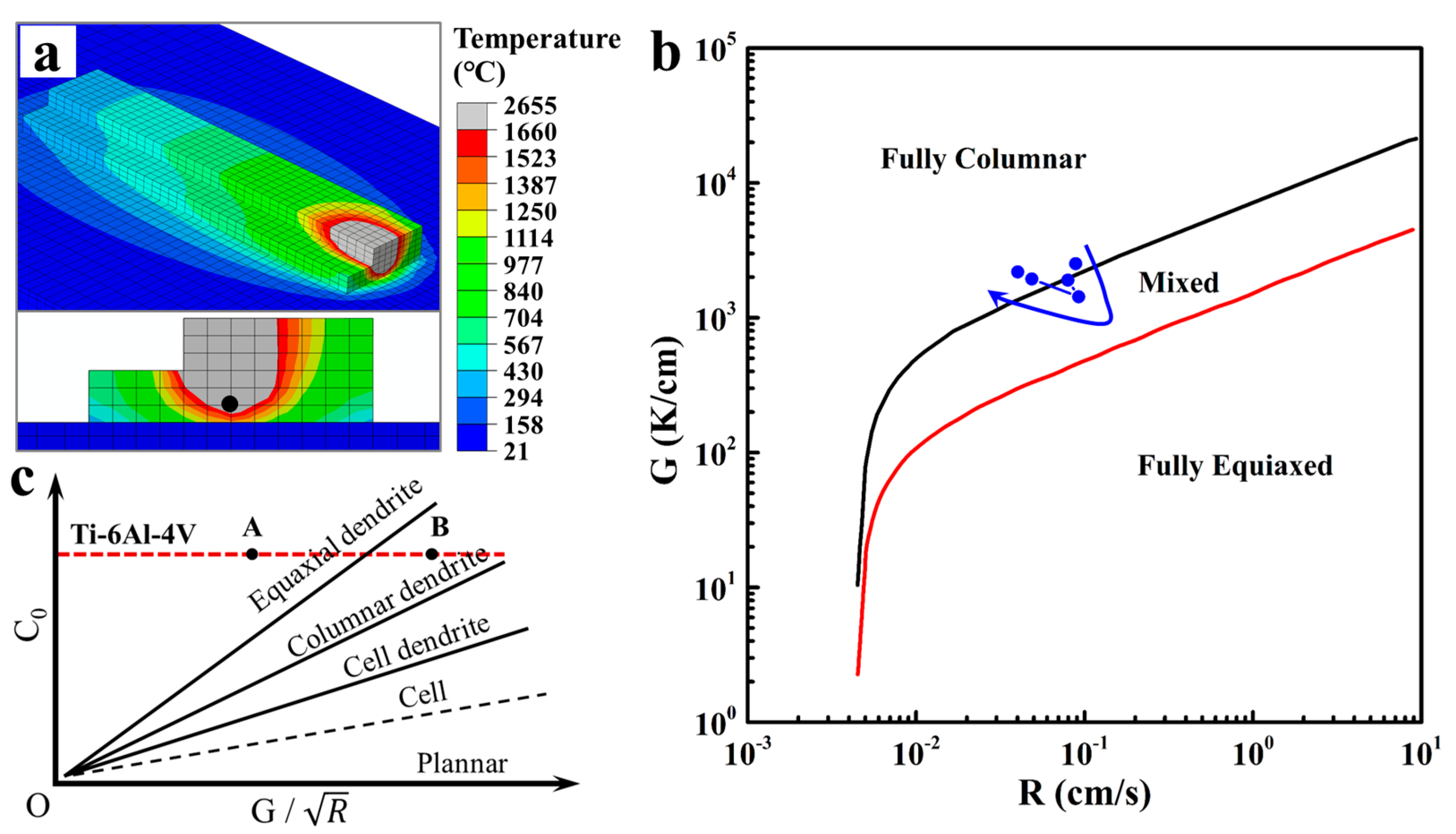
- With the increase of WMP, the macrostructure of Ti-6Al-4V changes from columnar grains (7 mm and 10 mm) to equiaxial grains (14 mm) firstly and then turns into large epitaxial columnar grains (19 mm and 22 mm). The variation of G and R is plotted on the solidification map of Ti-6Al-4V based on finite-element-method simulations of the additive manufacturing, which shows a similar grain morphology to those observed in the actual sections. It seems that equiaxial grains morphology can be obtained by controlling the cooling rate and thermal gradient through adjusting the manufacturing parameters.
- With WMP of 7 mm and 10 mm, rapid cooling rate can be obtained. The microstructure of the cross sections turns out to be needle-like α’ phase. However, with larger WMP, the microstructure changes into α lath morphology. With the increase of WMP, α-lath width becomes larger and microstructure turns into coarse α plate morphology due to the increasing heat input with larger WMP.
- Samples manufactured at small WMP (7 mm and 10 mm) exhibit higher strength than those manufactured at larger WMP. The decrease of elongation at failure can be attributed to the growing size of the prior β grains. Typically, when WMP reaches 22 mm, a very poor strength and elongation performance was observed, because of the much coarser α-lath within larger prior β grains at this time.
Acknowledgments
Author Contributions
Conflicts of Interest
References
- Wang, H.; Jiang, W.; Ouyang, J.; Kovacevic, R. Rapid prototyping of 4043 Al-alloy parts by vp-gtaw. J. Mater. Process. Technol. 2004, 148, 93–102. [Google Scholar] [CrossRef]
- Baufeld, B.; Biest, O.V.D.; Gault, R. Additive manufacturing of Ti-6AL-4V components by shaped metal deposition: Microstructure and mechanical properties. Mater. Des. 2010, 31, S106–S111. [Google Scholar] [CrossRef]
- Ding, D.; Pan, Z.; Cuiuri, D.; Li, H. A tool-path generation strategy for wire and arc additive manufacturing. Int. J. Adv. Manuf. Technol. 2014, 73, 173–183. [Google Scholar] [CrossRef]
- Shi, X.; Ma, S.; Liu, C.; Wu, Q.; Lu, J.; Liu, Y.; Shi, W. Selective laser melting-wire arc additive manufacturing hybrid fabrication of Ti-6AL-4V alloy: Microstructure and mechanical properties. Mater. Sci. Eng. 2017, 684, 196–204. [Google Scholar] [CrossRef]
- Acharya, R.; Das, S. Additive manufacturing of in 100 superalloy through scanning laser epitaxy for turbine engine hot-section component repair: Process development, modeling, microstructural characterization, and process control. Metall. Mater. Trans. A 2015, 46, 3864–3875. [Google Scholar] [CrossRef]
- Wang, F.; Williams, S.; Colegrove, P.; Antonysamy, A.A. Microstructure and mechanical properties of wire and arc additive manufactured Ti-6Al-4V. Metall. Mater. Trans. A 2013, 44, 968–977. [Google Scholar] [CrossRef]
- Wu, Q.; Ma, Z.; Chen, G.; Liu, C.; Ma, D.; Ma, S. Obtaining fine microstructure and unsupported overhangs by low heat input pulse arc additive manufacturing. J. Manuf. Process. 2017, 27, 198–206. [Google Scholar] [CrossRef]
- Rafi, H.K.; Karthik, N.V.; Gong, H.; Starr, T.L.; Stucker, B.E. Microstructures and mechanical properties of Ti-6AL-4V parts fabricated by selective laser melting and electron beam melting. J. Mater. Eng. Perform. 2013, 22, 3872–3883. [Google Scholar] [CrossRef]
- Guo, J.; Zhou, Y.; Liu, C.; Wu, Q.; Chen, X.; Lu, J. Wire arc additive manufacturing of AZ31 magnesium alloy: Grain refinement by adjusting pulse frequency. Materials 2016, 9, 823. [Google Scholar] [CrossRef]
- Simonelli, M. Microstructure Evolution and Mechanical Properties of Selective Laser Melted Ti-6AL-4V. Doctoral Thesis, Loughborough University, Loughborough, UK, 2014. [Google Scholar]
- Lu, Y.; Tang, H.; Fang, Y.; Liu, D.; Wang, H. Microstructure evolution of sub-critical annealed laser deposited Ti-6AL-4V alloy. Mater. Des. 2012, 37, 56–63. [Google Scholar] [CrossRef]
- Suryakumar, S.; Karunakaran, K.P.; Bernard, A.; Chandrasekhar, U.; Raghavender, N.; Sharma, D. Weld bead modeling and process optimization in hybrid layered manufacturing. Comput.-Aided Des. 2011, 43, 331–344. [Google Scholar] [CrossRef]
- Zhou, X.; Zhang, H.; Wang, G.; Bai, X. Three-dimensional numerical simulation of arc and metal transport in arc welding based additive manufacturing. Int. J. Heat Mass Transf. 2016, 103, 521–537. [Google Scholar] [CrossRef]
- Shan, X.Y.; Tan, M.J.; O’Dowd, N.P. Developing a realistic FE analysis method for the welding of a net single-bead-on-plate test specimen. J. Mater. Process. Technol. 2007, 192–193, 497–503. [Google Scholar] [CrossRef]
- Goldak, J.; Chakravarti, A.; Bibby, M. A new finite element model for welding heat sources. Metall. Tran. B 1984, 15, 299–305. [Google Scholar] [CrossRef]
- Ding, J.; Colegrove, P.; Mehnen, J.; Ganguly, S.; Almeida, P.M.S.; Wang, F.; Williams, S. Thermo-mechanical analysis of wire and arc additive layer manufacturing process on large multi-layer parts. Comput. Mater. Sci. 2011, 50, 3315–3322. [Google Scholar] [CrossRef]
- Zhang, L.; Michaleris, P. Investigation of lagrangian and eulerian finite element methods for modeling the laser forming process. Finite Elements Anal. Des. 2004, 40, 383–405. [Google Scholar] [CrossRef]
- Klingbeil, N.; Brown, C.; Bontha, S.; Kobryn, P.; Fraser, H. Prediction microstructure in laser deposition titanium alloys. In Proceedings of the Solid Freeform Fabrication Proceedings, Austin, TX, USA, August 2002; pp. 142–149. [Google Scholar]
- Ding, J. Thermo-Mechanical Analysis of Wire and Arc Additive Manufacturing Process. Ph.D. Thesis, Cranfield University, Cranfield, Bedfordshire, UK, 2012. [Google Scholar]
- Kobryn, P.A.; Semiatin, S.L. The laser additive manufacture of Ti-6AL-4V. J. Miner. Met. Mater. Soc. 2001, 53, 40–42. [Google Scholar] [CrossRef]
- Kobryn, P.A.; Semiatin, S.L. Microstructure and texture evolution during solidification processing of Ti-6Al-4V. J. Mater. Process. Technol. 2003, 135, 330–339. [Google Scholar] [CrossRef]
- Fu, J.; Gong, L.; Zhang, Y.; Wu, Q.; Shi, X.; Chang, J.; Lu, J. Microstructure and mechanical properties of Ti-6Al-4V fabricated by vertical wire feeding with axisymmetric multi-laser source. Appl. Sci. 2017, 7, 227. [Google Scholar] [CrossRef]
- Baufeld, B.; Biest, O.V.D.; Dillien, S. Texture and crystal orientation in Ti-6Al-4V builds fabricated by shaped metal deposition. Metall. Mater. Trans. A 2010, 41, 1917–1927. [Google Scholar] [CrossRef]
- Lütjering, G. Influence of processing on microstructure and mechanical properties of (α + β) titanium alloys. Mater. Sci. Eng. A 1998, 243, 32–45. [Google Scholar] [CrossRef]
- Leyens, C.; Peters, M. Titanium and Titanium Alloys; Wiley-VCH: Weinheim, Germany, 2003. [Google Scholar] [CrossRef]


| No. | WFS, cm/min | Peak Current, A | Hatch Distance, mm | Heat Input, mJ/mm | Welding Speed, mm/min | Base-to-Peak Current Ratio | Peak Time Ratio | Pulse Frequency, Hz | Arc Length, mm |
|---|---|---|---|---|---|---|---|---|---|
| 1 | 100 | 90 | 4.2 | about 21,350 | 100 | 30% | 50% | 1.2 | 4 |
| 2 | 200 | 140 | 5.1 | ||||||
| 3 | 300 | 170 | 7.2 | ||||||
| 4 | 400 | 210 | 9.0 | ||||||
| 5 | 500 | 270 | 9.8 |
| WFS, cm/min | WMP, mm | Total Width, mm | Total Height, mm | Layer Thickness, mm | Average Grain Width, mm |
|---|---|---|---|---|---|
| 100 | 7 | 14.5 | 5.7 | 1.9 | 0.72 |
| 200 | 10 | 19.0 | 8.1 | 2.7 | 0.92 |
| 300 | 14 | 23.1 | 12.3 | 4.1 | 0.98 |
| 400 | 19 | 32.8 | 13.5 | 4.5 | 1.05 |
| 500 | 22 | 35.2 | 16.5 | 5.5 | 1.23 |
| WMP, mm | Thermal Gradient (G), k/cm | Solidification Velocity (R), cm/s | , k cm−1.5 s−0.5 |
|---|---|---|---|
| 7 | 2516 | 0.08868 | 8449 |
| 10 | 1903 | 0.07974 | 6739 |
| 14 | 1431 | 0.09229 | 4710 |
| 19 | 1938 | 0.04866 | 8786 |
| 22 | 2189 | 0.04015 | 10,925 |
© 2017 by the authors. Licensee MDPI, Basel, Switzerland. This article is an open access article distributed under the terms and conditions of the Creative Commons Attribution (CC BY) license (http://creativecommons.org/licenses/by/4.0/).
Share and Cite
Wu, Q.; Lu, J.; Liu, C.; Fan, H.; Shi, X.; Fu, J.; Ma, S. Effect of Molten Pool Size on Microstructure and Tensile Properties of Wire Arc Additive Manufacturing of Ti-6Al-4V Alloy. Materials 2017, 10, 749. https://doi.org/10.3390/ma10070749
Wu Q, Lu J, Liu C, Fan H, Shi X, Fu J, Ma S. Effect of Molten Pool Size on Microstructure and Tensile Properties of Wire Arc Additive Manufacturing of Ti-6Al-4V Alloy. Materials. 2017; 10(7):749. https://doi.org/10.3390/ma10070749
Chicago/Turabian StyleWu, Qianru, Jiping Lu, Changmeng Liu, Hongli Fan, Xuezhi Shi, Jie Fu, and Shuyuan Ma. 2017. "Effect of Molten Pool Size on Microstructure and Tensile Properties of Wire Arc Additive Manufacturing of Ti-6Al-4V Alloy" Materials 10, no. 7: 749. https://doi.org/10.3390/ma10070749