
A New Energy-Critical Plane Damage Parameter for Multiaxial Fatigue Life Prediction of Turbine Blades


Center for System Reliability & Safety, University of Electronic Science and Technology of China, Chengdu 611731, China
*
Author to whom correspondence should be addressed.
Materials 2017, 10(5), 513; https://doi.org/10.3390/ma10050513
Submission received: 22 March 2017
/
Revised: 2 May 2017
/
Accepted: 4 May 2017
/
Published: 8 May 2017
(This article belongs to the Special Issue The Life of Materials at High Temperatures)
Abstract
:As one of fracture critical components of an aircraft engine, accurate life prediction of a turbine blade to disk attachment is significant for ensuring the engine structural integrity and reliability. Fatigue failure of a turbine blade is often caused under multiaxial cyclic loadings at high temperatures. In this paper, considering different failure types, a new energy-critical plane damage parameter is proposed for multiaxial fatigue life prediction, and no extra fitted material constants will be needed for practical applications. Moreover, three multiaxial models with maximum damage parameters on the critical plane are evaluated under tension-compression and tension-torsion loadings. Experimental data of GH4169 under proportional and non-proportional fatigue loadings and a case study of a turbine disk-blade contact system are introduced for model validation. Results show that model predictions by Wang-Brown (WB) and Fatemi-Socie (FS) models with maximum damage parameters are conservative and acceptable. For the turbine disk-blade contact system, both of the proposed damage parameters and Smith-Watson-Topper (SWT) model show reasonably acceptable correlations with its field number of flight cycles. However, life estimations of the turbine blade reveal that the definition of the maximum damage parameter is not reasonable for the WB model but effective for both the FS and SWT models.
1. Introduction
High thrust-to-weight ratios and high levels of reliability are required for modern aircraft turbine engines. As one of the fracture critical components in aircraft engines, the turbine blade to disk attachments are often subjected to complex loadings, including high rotational speeds and vibrations at high temperatures. Its failure results from a number of mechanisms under the turbine operating conditions of high rotational speeds at elevated temperatures [1,2]. In general, the integrity of the turbine blades can be threatened by three possible damage mechanisms: (a) multiaxial fatigue, including both high cycle fatigue (HCF) and low cycle fatigue (LCF); (b) creep ruptures; (c) high temperature corrosion [3,4,5,6,7]. The amplitude of vibration loads induced by the gas flow is much smaller than that of centrifugal loads and hence vibrations generally give rise to HCF failure. In contrast, the effect of centrifugal loads is frequently considered as the cause of LCF failure [6,7]. It is especially noticeable that high contact stresses in the interfaces of turbine blade to disk and short oscillations might cause fretting wear and ultimately failure of this contact system [8,9,10,11]. To predict the usage life of turbine blades, or more precisely the time to crack initiation, the constitutive behavior of the blade materials should be known for computing the stress and strain state in the component.
For failure mechanism analysis of the turbine blade, Kermanpur et al. [12] indicated that insufficient clearance between turbine blade root and disk in the dovetail region may lead to high stress and stress concentration which initiate several cracks and eventually cause the complete failure of the turbine blade. Golden et al. [13] developed a fracture mechanics-based crack growth life prediction model for dovetail fretting fatigue analysis. They calculated contact stress and bulk stress by FE analysis and used them as inputs for life estimation analysis. Chen et al. [14] modified the strain range partitioning method for turbine blade life prediction by using stress-strain response of pure LCF and creep-fatigue interaction. However, they ignored the effects of contact and notch for the fir-tree region of the turbine blade. As the main failure mode of turbine blades, LCF under high temperature results from multiaxial cyclic loads and stress concentration caused by geometrical discontinuities of the turbine blade, which makes it necessary for the development of multiaxial fatigue failure criteria. Among them, as one of the commonly-used methods for multiaxial fatigue analysis, critical plane criterion provides reasonably acceptable life predictions for components in complex stress-strain states, which is based on the physical failure phenomenon and considers a specific plane with maximum fatigue damage.
Until now, various critical plane approaches for multiaxial fatigue analysis have been developed, including the Fatemi-Socie [15], Wang-Brown [16,17] and Smith-Watson-Topper [18] models (FS, WB, and SWT, respectively). Brown and Miller [19] developed a critical plane model which considered the cyclic shear and normal strain on the plane of maximum shear strain. Based on this, Wang and Brown [16,17] extended it for mean stress effect correction. However, Fatemi and Socie [15] put forward a model by substituting normal stress for the normal strain term, which explained the difference between tension and torsion loading, and also included the mean stress and non-proportional hardening effects. Smith, Watson and Topper [18] pointed out that fatigue failure is predominantly caused by crack growth on planes of maximum principle strain or stress. It was acknowledged that the SWT model is suitable to predict life for materials failure under the tensile cracking mode and has relatively poor life-prediction accuracy for pure torsion and multiaxial fatigue loadings [20,21,22,23]. The SWT parameter was modified by Jiang and Sehitoglu [24] to consider the general crack cracking mode and has a reasonable prediction for different crack behaviors with appropriate values of material constant [25]. Researches in [26,27,28] indicate that the effects of mean stress on fatigue life should be considered in practical engineering applications. According to this, Ince et al. [29] developed two different forms of multiaxial fatigue damage parameters based on generalized strain energy, which define the specific planes with the maximum amount of fatigue damage. Besides, probabilistic formulations of multiaxial fatigue damage have been investigated by [30,31,32,33,34,35], which open new perspectives for introducing the probabilistic approaches to a number of very general problems for estimating fatigue life of engineering components.
In the current work, considering different failure types, this paper attempts to propose a simple critical plane damage parameter based on an energy concept and evaluate different criteria with a maximum damage parameter as the critical plane for multiaxial fatigue life prediction of a turbine disk-blade contact system. The rest of this paper is organized as follows. Section 2 provides a general procedure by using critical plane approach for multiaxial fatigue analysis. Section 3 develops a new critical plane model and defines a critical plane of the maximum damage parameter in the models of WB, FS and SWT for multiaxial fatigue life prediction of turbine blade alloy GH4169. Section 4 performs model validation under uniaxial and multiaxial loading and analysis of stress-strain states of a turbine disk-blade contact system to predict its number of flight cycles. The influence of asymmetrical centrifugal loads is investigated for a turbine disk-blade contact system due to the rotations under high temperatures. Section 5 concludes the current investigation in this paper.
2. Critical Plane Approach for Multiaxial Fatigue Analysis
Critical plane approaches were mainly developed on the basis of experimental observations of the nucleation and growth of cracks during loadings. It is generally recognized that fatigue cracks nucleate and propagate on a critical plane [36]. They usually have a better life prediction accuracy under multiaxial stress/strain states than uniaxial fatigue models. Numerous critical plane criteria based on various assumptions and parameters have been developed to describe the fatigue failure processes of different materials. These approaches are typically based on either the maximum principal strain/stress plane or the maximum shear strain/stress plane for different failure types, and can be classified into three categories [37], namely stress criteria, strain criteria and the criteria combining both stress and strain (also energy-based criteria) [15,16,17,18,38,39,40]. Using the critical plane approach, it is the most important to find the critical plane. Figure 1 shows that the critical plane of a component subjected to a complex stress state is usually in the region of its stress-strain concentration.
The body subjected to complex loadings results in three-dimensional time-varying states of stress and strain at internal reference point , which is the base to define a local coordinate system, . The stress and strain state at the above point is then fully described by the following stress and strain tensor:
where , represents the time period of a load cycle; , , , , and are the normal stress and strain components, respectively, whereas , , , , and are the shear stress and strain components.
A generic material plane represented by its unit normal vector as shown in Figure 1 can be defined by the angles and . According to the current schematization in Figure 1, is the angle between the projection of unit vector n on the plane and the -axis and is the angle between unit vector and the -axis. While the second reference system, Oanb, can also be defined by the following three unit vectors determined by the angles and as defined above:
The unit vector represents a generic direction on the plane which passes through the point is as follows:
where is the angle between direction and the -axis. The instantaneous values of the normal stress and strain of the plane can directly be computed as:
The shear stress and shear train along the direction can be expressed as:
The general steps to determine the critical plane are outlined as follows (using the maximum shear strain-based critical plane as an example):
- (1)
- Conduct an elastic-plastic FE analysis for the component under given loading conditions to determine the time-variable stress and strain tensors at the critical region;
- (2)
- Using stress and strain tensors to express the states of stress and strain and three direction vectors, , and at the internal reference point of element where there is a plane with maximum shear strain in the whole critical locations to determine the candidate material planes through every 5° to change the directions of and , , ;
- (3)
- Since the shear strain directly calculated from Equation (8) is a time consuming process by involving three cycles of angle calculation, then shear strains and can be obtained respectively along the direction and similar to Equation (8). The shear strain amplitude acting on the th candidate material plane can be determined by:where is the number of subdivisions per cycle (each cycle is divided into p subdivisions).
- (4)
- Find critical plane through comparing the value of shear strain amplitude of each candidate material planes to determinate the location of the maximum one;
- (5)
- The normal strain ranges acting on the critical plane can be calculated by:where can be calculated using Equation (6).
- (6)
- Calculate normal stress of each candidate plane according to Equation (5). The maximum normal stress of critical plane is calculated by:
3. Proposed Energy-Critical Plane Damage Parameter for Multiaxial Fatigue Analysis
In this section, three commonly-used critical plane models will be introduced, including those developed by Wang-Brown [16,17], Fatemi-Socie [15] and Smith-Watson-Topper [18]. These models combine multiaxial fatigue criteria with Manson-Coffin curve under uniaxial loading conditions. The FS and WB models with a material constant are designed for material exhibiting shear cracking behavior. The SWT model has a simple form without any fitted material constants, which is suitable for multiaxial fatigue life prediction of materials under normal cracking dominated failure. The original definition of the critical plane is the maximum shear strain or the maximum normal strain of the plane as the critical plane [15,16,17,18]. In the current investigation, a new energy-based critical plane damage parameter is proposed and maximum damage parameter (MDP)-based critical planes for the three models mentioned above are investigated for GH4169 to predict the life of uniaxial and multiaxial fatigue. Then, the predicted lives calculated by using original critical planes are compared.
3.1. Wang-Brown Model with Maximum Damage Parameter
Assuming that fatigue failure is controlled by the maximum shear strain range, Kandil, Brown and Miller [41] proposed a model under biaxial loadings, in which the normal strain range on the maximum shear strain plane per cycle plays a vital role in controlling crack growth:
where ; ; and are respectively the elastic and plastic Poisson’s ratio of the material; is the maximum shear strain amplitude; is the normal strain range on the maximum shear strain plane; and are the fatigue strength coefficient and fatigue ductility coefficient, respectively; is fatigue strength exponent, is fatigue ductility exponent, is the Young modulus, is the number of cycles to failure, is a material constant derived by fitting fatigue data under uniaxial cyclic torsion, bending or tension-compression loadings.
Since the Kandil-Brown-Miller model in Equation (12) ignored the effect of mean stress, Wang and Brown [16,17] referred to the mean stress approach of Morrow and extended Equation (12) for mean stress correction:
In this analysis, the maximum shear strain plane for the critical plane is obtained by the following definition:
For fully reversed uniaxial loadings, the maximum shear strain amplitude, the normal strain range and mean normal stress on the critical plane can be derived as:
where and are axial strain and axial mean stress in uniaxial tension and compression fatigue tests, respectively.
3.2. Fatemi-Socie Model with Maximum Damage Parameter
Fatemi and Socie [15] developed a multiaxial fatigue model for shear cracking failure modes. Such a parameter of the FS model, also named as the equivalent shear strain amplitude , considers both crack initiation and propagation because the parameter includes shear strain amplitude for crack initiation, and maximum normal stress on the plane of maximum shear strain range for crack propagation, which is expressed as:
where is the yield strength, is the shear fatigue strength coefficient, is the shear fatigue ductility coefficient, and are the shear fatigue strength exponent and shear fatigue ductility exponent, G is the shear modulus, and k is the material constant obtained in the same way as the constant in WB’s parameter in Equation (12). The maximum normal stress , is one-half of the maximum axial stress under uniaxial tension-compression fatigue tests. The yield strength can be obtained by the 0.05% offset rule as ():
where and are the cyclic strength coefficient and cyclic strain hardening exponent, respectively.
The original critical plane of the FS model is the maximum shear strain plane [15], which is reasonable for fatigue analysis with shear failure modes. The FS model considers that fatigue failure of a material is due to the combined effect of shear strain and normal stress of the critical plane. However, there are several maximum values of shear strain on the candidate plane of different orientations for material under the actual multiaxial loadings. Similarly, in order to explain the maximum damage to the plane, a critical plane for the FS model is defined as:
3.3. Smith-Watson-Topper Model with Maximum Damage Parameter
The SWT model was originally developed to account for the mean stress effect under uniaxial loadings and it also can be used for multiaxial fatigue analysis of materials that exhibit normal cracking behavior [18]. The SWT parameter for multiaxial fatigue is based on the maximum principle strain amplitude and the maximum stress on principle range plane:
where is the maximum normal strain amplitude. The maximum normal stress normal to critical plane is , which makes it reasonable to include mean stresses during multiaxial loading and non-proportional hardening effects [18]. The original critical plane of the SWT model is defined as the plane with maximum normal strain. In this analysis, the critical plane is given by:
3.4. New Energy-Critical Plane Damage Parameter
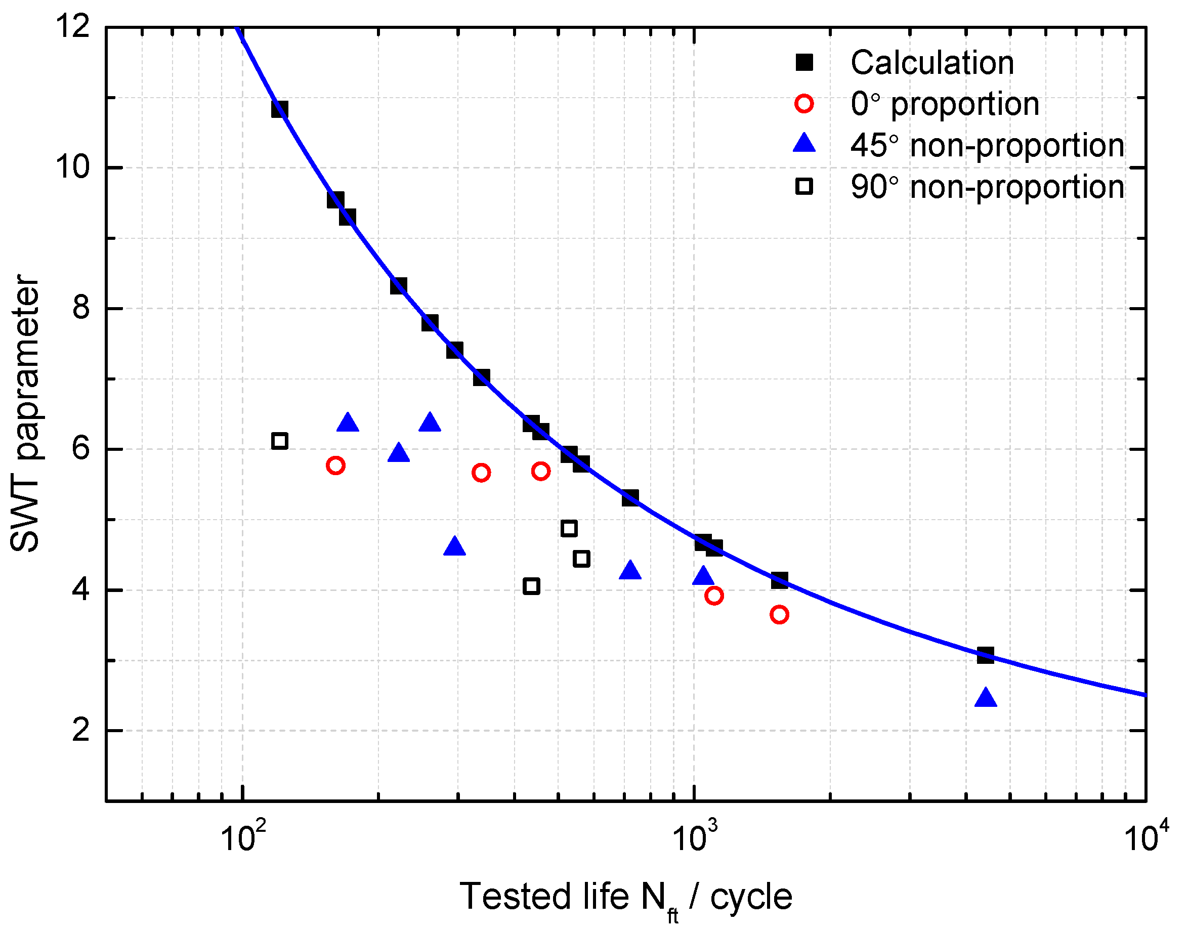
The SWT model as the critical plane model is also considered as an energy-based approach and its parameter can be understood as normal energy which has shown a satisfactory life prediction for uniaxial fatigue but not for multiaxial fatigue [20]. It was found that SWT damage parameters are smaller than the calculated parameter as shown in Figure 2, and tends to overestimate fatigue life of GH4169 under multiaxial loadings [20,21,22,23]; more details on experimental results and data can be found in Section 4. The reason is that it doesn’t consider the effect of shear behavior. Liu [42] proposed virtual strain energy including shear and normal work, which is reasonable and feasible for multiaxial fatigue life prediction. However, it ignored the effects of mean stress on fatigue life. Glinka et al. [43,44] proposed a damage parameter including normal energy density and shear energy density and then modified the model to consider the effect of mean stress. An evolutionary parameter from the SWT model [45] is the combination of work of normal stress and shear stress on the critical plane. However, few attentions were paid to the effect of shear stress-strain on normal stress-strain, which is still unclear. Therefore, it is necessary to investigate the influence of shear behavior to normal work on the plane with the maximum normal strain. Then it was found that the maximum principle stress is less than the maximum principal strain multiplied by the Young modulus as shown in Figure 3. It is not surprising to obtain the result, considering the Ramberg-Osgood relation [46]. However, it is also reasonable to assume that shear strain of the critical plane makes it easier for normal stress to produce normal strain and obviously normal stresses which produce the same normal strain on a plane with shear behavior and a plane without shear behavior are different. In order to confirm this assumption, four normal stress-strain relationships of the maximum principle strain plane are introduced as follows:
where and are real normal stress and strain amplitude on the plane with maximum normal strain under uniaxial tension-torsion loading, respectively; and are real normal stress and strain amplitude on the same plane under the same tension loading level controlled by strain; and are the calculated normal stresses amplitude on plane with shear behavior by Ramberg-Osgood equation and Young modulus, respectively. The relationship of - and - can be considered to occur on the plane with shear behavior and no shear behavior, respectively.
As shown in Figure 3, the normal stress level on the plane with shear behavior is always lower than that of the Ramberg-Osgood curve. Although the level of normal stress on the plane without shear behavior is higher than the stress level on the Ramberg-Osgood curve, their stress levels tend to be consistent with the increasing strain, which is reasonable because the Chaboche constitutive model [47] of the material for analysis is based on uniaxial plastic strain experimental data and yield strength is calculated from 0.05% strain. The reason why the fatigue life predicted by the SWT model has shown a good agreement with experimental life under uniaxial loadings is that there is almost no shear behavior on the plane of maximum principle strain. Therefore, the SWT damage parameter can represent real normal work in uniaxial fatigue. However, in multiaxial fatigue, the value of affected by the shear behavior is not enough to be the stress term of the SWT damage parameter, which accounts for lower damage parameter of SWT when applied to multiaxial fatigue. Note that is between the stress level of Ramberg-Osgood curve and - curve as shown in Figure 3. In order to obtain the required normal strain damage considering the effects of shear behavior, maximum normal stress , is replaced with and an energy-critical plane (ECP) damage parameter for multiaxial fatigue dominated by tensile-dominate failure mode is given as follows:
where the left part of Equation (25) is an energy-critical plane damage parameter for multiaxial fatigue analysis with tension-dominate failure mode. The difference between the ECP for tension-dominate failure mode and the SWT parameter is considered to be the damage contributed by the shear behavior. The substituted stress term, , in this model makes it feasible to account for the mean stress effect in multiaxial fatigue. Similarly, an energy-critical plane damage parameter for shear-dominate failure mode is derived as
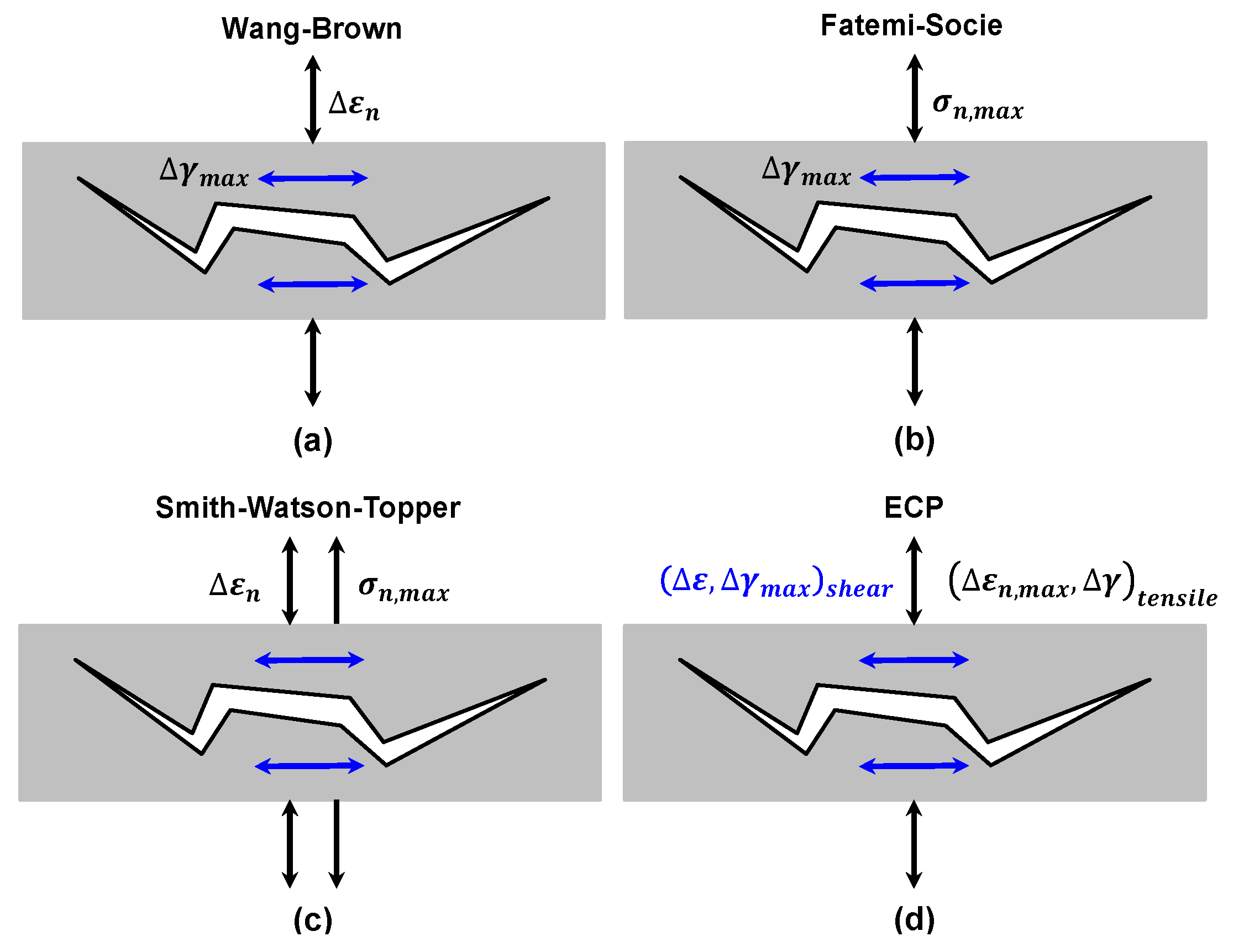
Unlike the FS and WB models, it’s worth noting that when using Equations (25) and (26) for multiaxial fatigue analysis under different failure types, no extra fitted material constants will be needed. Figure 4 illustrates the fatigue fracture mechanisms of the four abovementioned models.
4. Experimental Validation
4.1. Model Vvalidation to Turbine Blade Alloy GH4169
In this section, in order to obtain the materials constant and validate the prediction accuracy of the abovementioned critical plane models (including the proposed definition of the critical plane), two sets of uniaxial and multiaxial fatigue data of turbine blade alloy GH4169 were introduced from the literature [48,49]. The experiments were carried out under strain-controlled fully-reversed uniaxial tension-compression, tension-torsion loading of 0° proportion, 45° non-proportion and 90° non-proportion with triangle wave and sine wave at 650 °C. Material properties and multiaxial fatigue data of GH4169 at 650 °C are listed in Table 1 and Table 2, respectively.
The majority of the considered material properties can be derived from the tension-compression uniaxial fatigue data [50,51]. When the constants of torsion fatigue are not available, they can be estimated from the corresponding uniaxial fatigue constants by using von Mises’s criterion, as suggested by [52]:
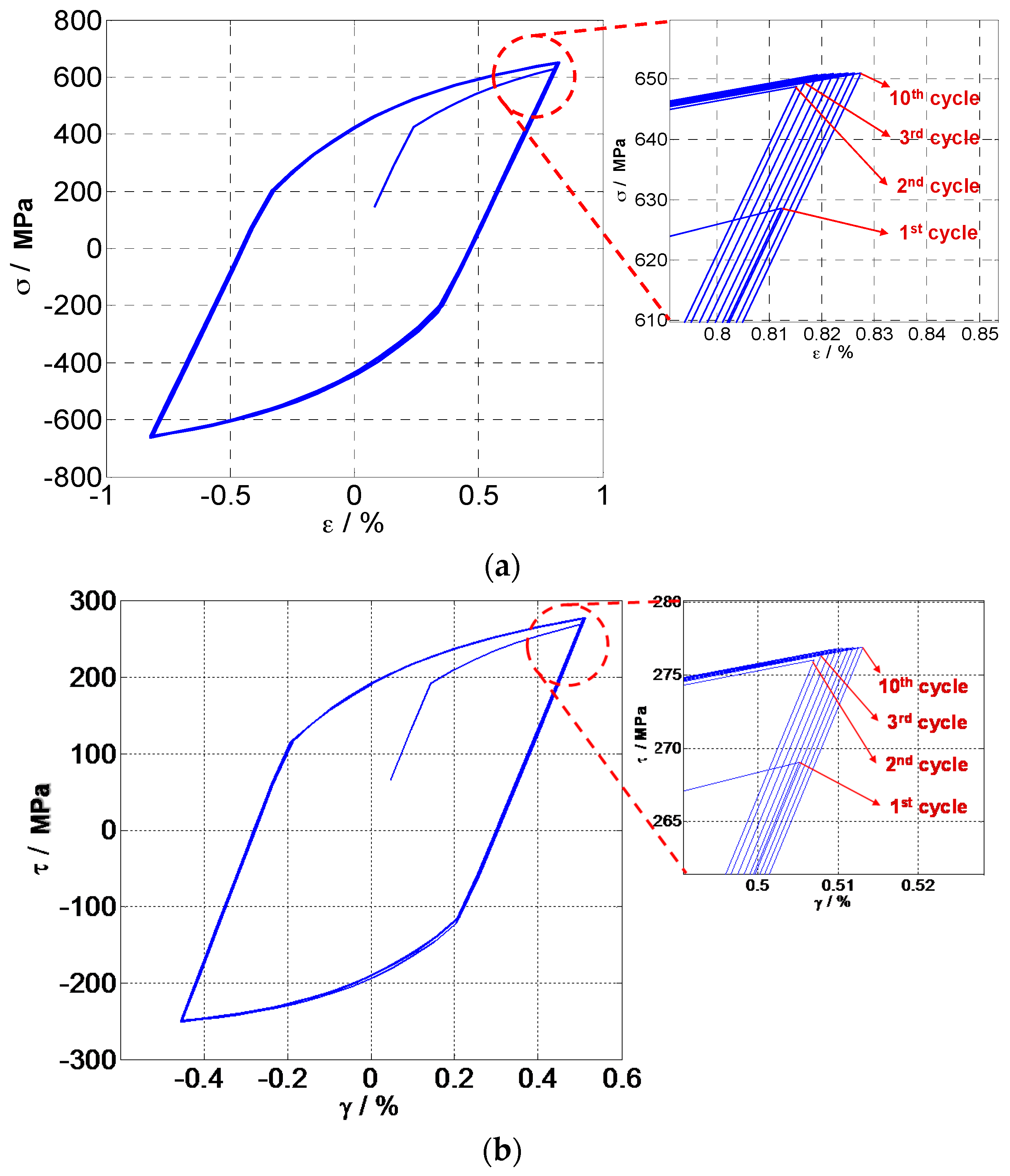
Thus, the FS model can be implemented to predict life by using uniaxial tension-compression fatigue data. Based on the above uniaxial fatigue data, material constants of the FS and WB models for GH4169 were estimated as and , respectively. Approximate modeling of material cyclic behavior is needed to correctly characterize the material cyclic response. The kinematic hardening was modeled by using the non-linear Chaboche model [47] with three backstresses. Cyclic stress-strain responses of critical planes have been analyzed to determine the input of stress and strain tensor for life prediction. The relationship of axial stress-strain and torsion stress-strain is shown in Figure 5, which shows that the hysteresis loop at the second cycle and third cycle begins to stabilize with the increase of loading cycles. Due to the plastic deformation reached at the first load application and consequent lower residual stresses, the material exhibited a certain cyclic hardening. Jiang et al. [53] found that fatigue damage produced by the stable stress-strain hysteresis loop can provide a good estimate of fatigue life when the transient cyclic behavior is not pronounced and a stabilized stress-strain response can be identified. In this analysis, fatigue life prediction is conducted based on the stress-strain state of GH4169 at the second load cycle, especially for the WB model which includes the mean stress term.
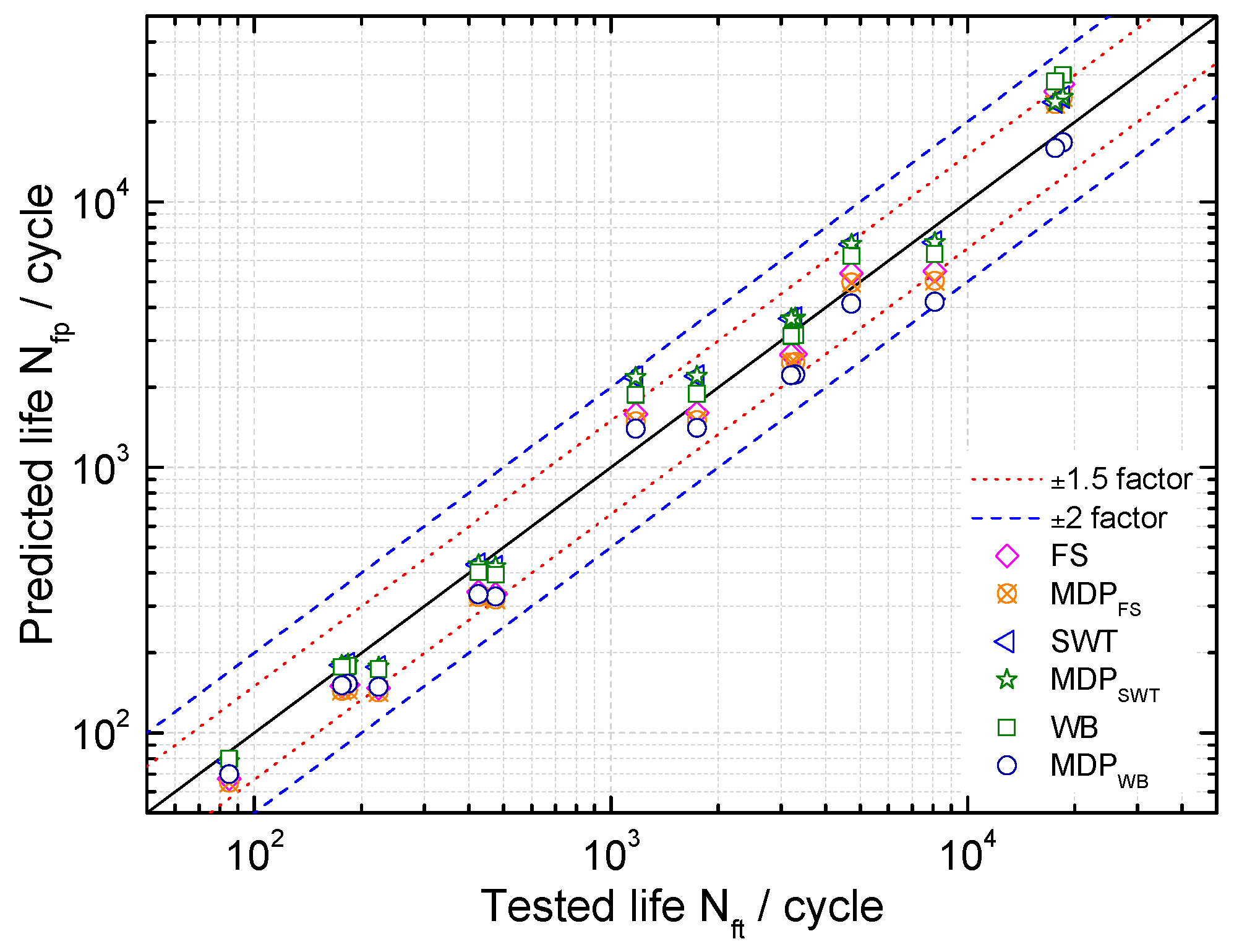
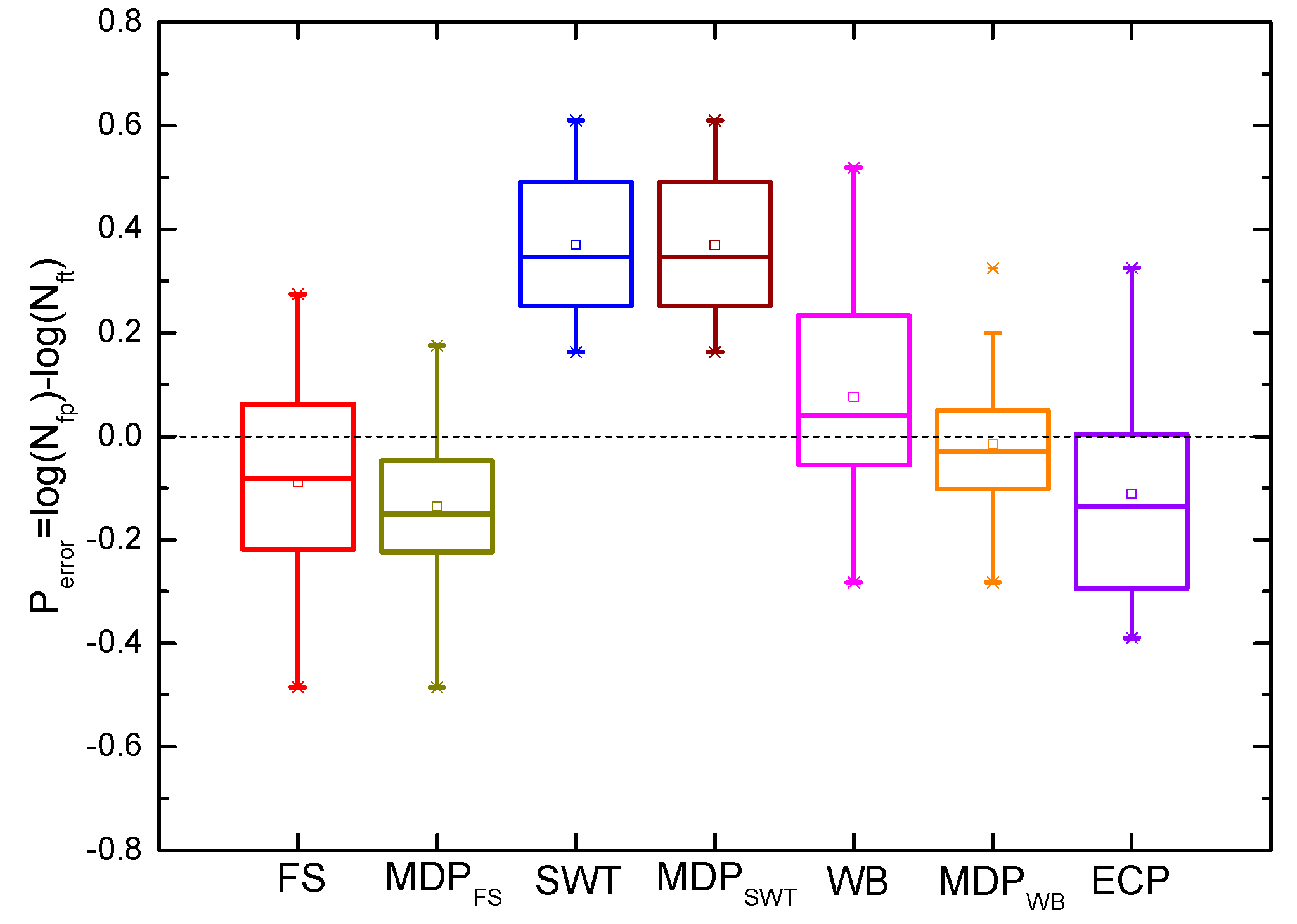
Life prediction results of these critical plane models for uniaxial tension-compression fatigue are shown in Figure 6. Maximum damage parameter (MDP) represents the predicted lives of these models with the critical plane of maximum damage parameters. A good agreement for these models being considered can be observed especially by applying the SWT and MDPSWT with 92.8% of the results within the scatter band. For the FS and WB models with different critical planes, the life prediction results are within the band. In order to more visually show the differences between these models, a probability analysis has been conducted on model prediction errors as [27,28]:
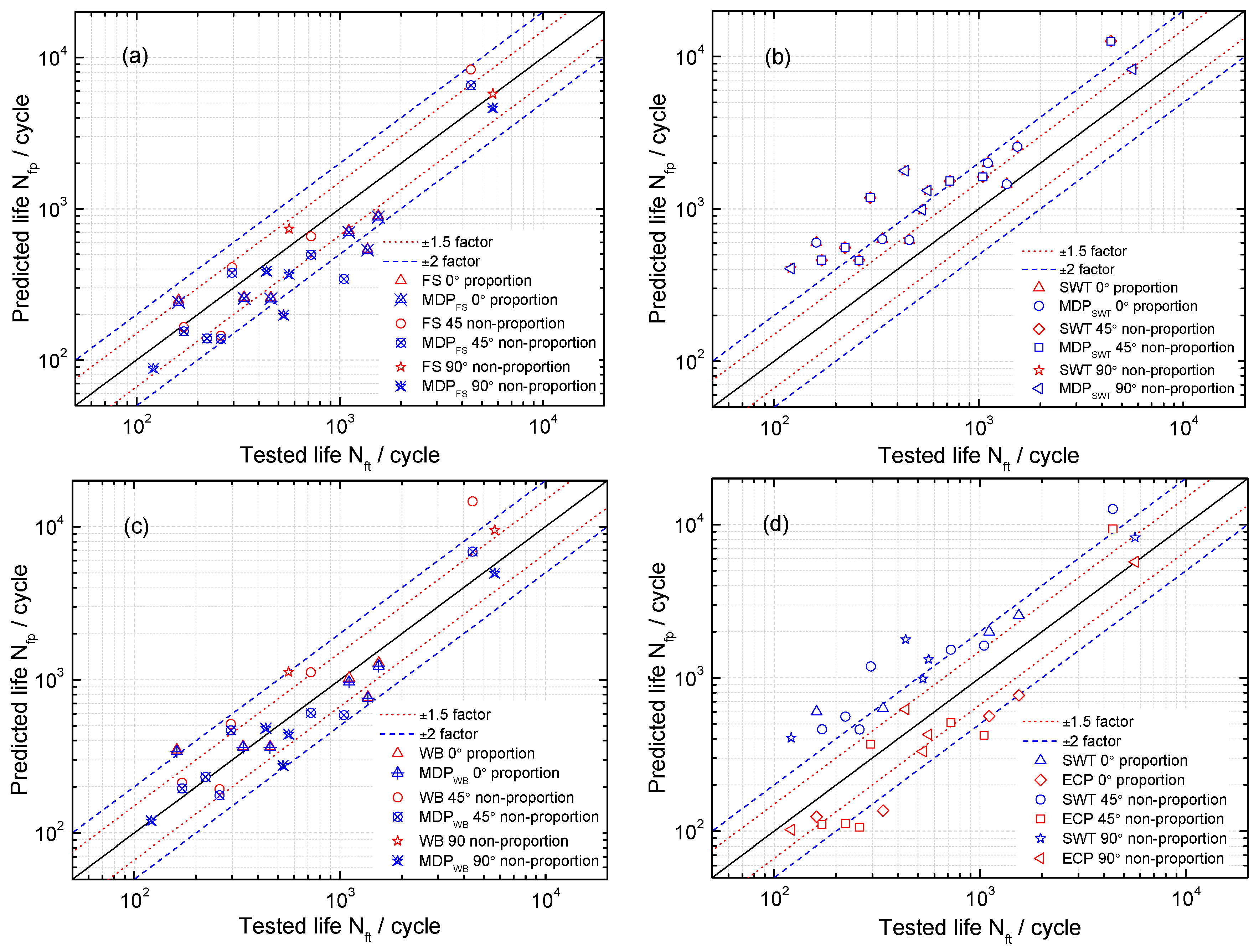
where and are the predicted life and tested life, respectively. It can be observed from Figure 7 that the SWT, MDPSWT and WB models give more accurate predictions than others under uniaxial loadings for GH4169. Moreover, Figure 7 and Figure 8 show the predicted lives by the critical plane models defined by the maximum damage parameter are more conservative than that of the traditional one, which still has shown a good ability to predict life of components due to the small error. However, the predicted lives by the SWT model with two different definitions of critical plane are the same as shown in Figure 7 and Figure 8. Figure 9 shows that these models defined by two critical planes all have good capability for multiaxial fatigue life prediction, except for the SWT model. Half of the predicted life by the SWT model is out of scatter factor-of-two lines on the non-conservative side. However, the ECP damage parameter shows more accurate multiaxial fatigue life predictions than the traditional one, since only 3 of 16 prediction points fall out of scatter factor-of-two lines.
4.2. Model Validation to a Turbine Disk-Blade Contact System
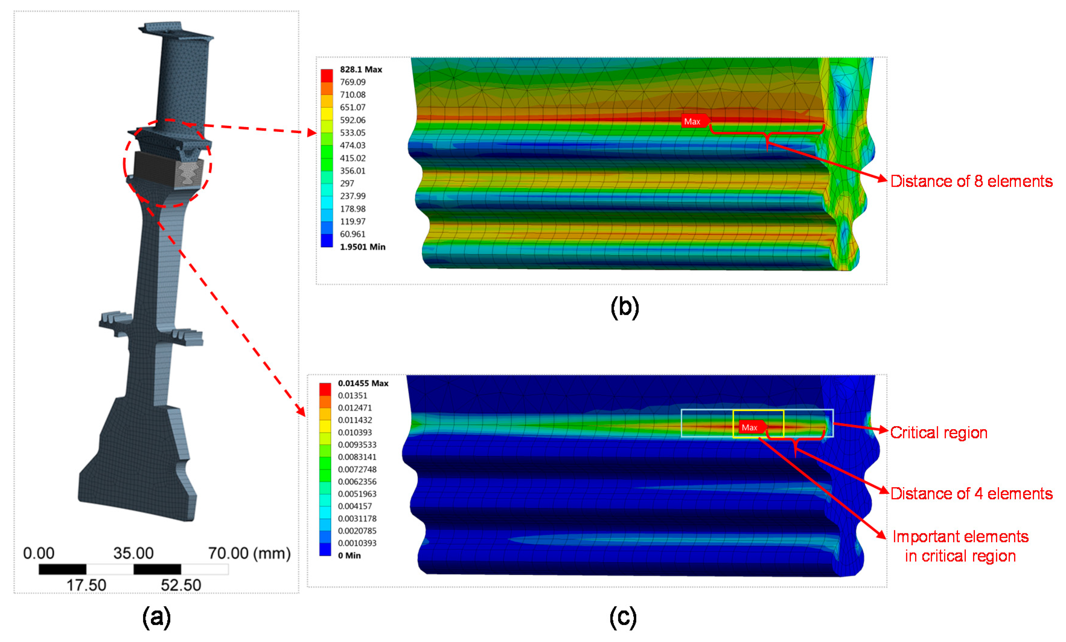
In the finite element analysis (FEA) of a turbine blade, material properties of GH4169 in Table 2 are introduced and the applied boundary conditions were centrifugal loads at the high constant temperature of 650 °C. In order to truly reflect the centrifugal force on the impact of the turbine blade, FE analysis of a turbine disk-blade contact system was performed and the mesh is shown in Figure 10. Twenty node hexahedral elements were chosen for the turbine disk and fir-tree root of the blade and the ten node tetrahedral elements for the blade body. The contact area is applied with surface-to-surface contact elements. The mesh of fir-tree root was refined for obtaining a more precise analysis on the stress and strain state of the turbine blade. Load spectrum of the turbine blade is given according to its real flight missions, which consists of three typical cycles (due to confidentiality, all the results have been processed): 0-maximum-0 (0-450r/s-0), idle-maximum continue-idle (230r/s-450r/s-230r/s), and cruise-maximum continue-cruise (431r/s-450r/s-431r/s).
FEA result of the turbine blade at the 0-maximum-0 cycle was shown in Figure 10. It shows that the most dangerous region is at the fir-tree region, which is consistent with the conclusion of Sinclair and Cormier [8] that the contact stress analysis of dovetail attachments is critical in the life prediction of turbine blade to disk attachments. There is a plastic strain field at the first tooth of the fir-tree tenon due to the compression stress caused by the geometric volume expansion due to centrifugal loads of the blade at high temperatures. The locations with the maximum von-Mises stress and the maximum plastic strain are different. The position of the maximum von-Mises stress is a distance of 8 elements away from the edge of the fir-tree root and the position of maximum equivalent plastic strain is the distance of 4 elements. It is worth mentioning that the maximum shear strain and the maximum damage parameter are not in the position of the maximum von-Mises stress, but in the region near the maximum equivalent plastic strain, which is similar to the conclusions of Maktouf [50]. It was found that the four elements at the region of maximum equivalent plastic strain are the most important elements to be considered for life prediction. Determine the element by the maximum value of shear strain, normal strain, or damage parameter (determined by the definition of different critical planes) to be used for fatigue life prediction of the turbine blade.
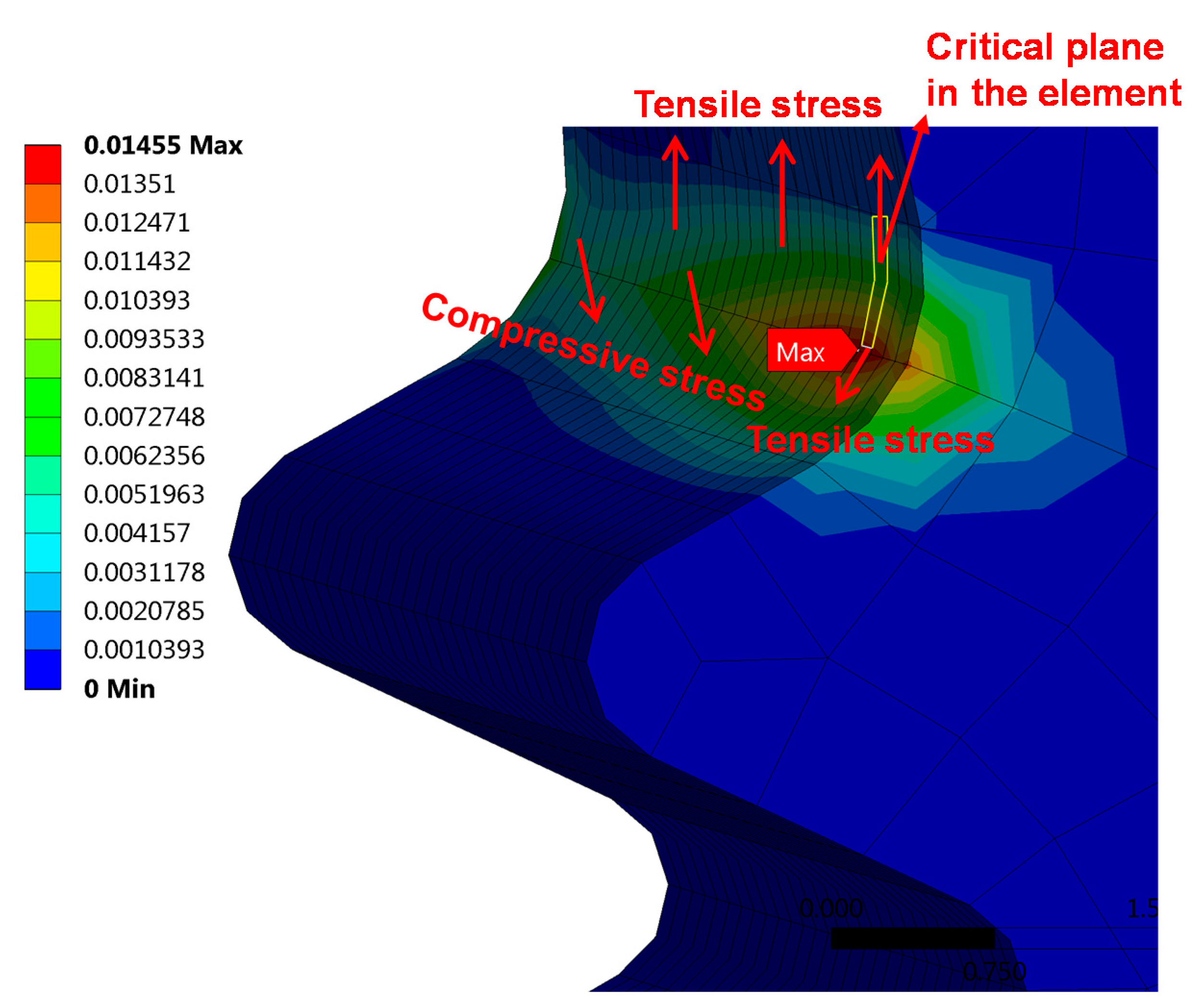
Table 3 lists the predicted lives of the turbine blade under different flight conditions. Note that the life prediction results of the three models with two definitions of the critical plane are different from each other. Although these models are effective under uniaxial or multiaxial fatigue loading [15,16,17,18], once in practical applications, especially for components with more complex failure modes such as turbine blades, the application of these models has to be discussed in terms of the actual situation. From Figure 11 it appears that the element in which the critical plane lies is subjected to the tensile stress of the upper elements. The lower elements are subjected to the compressive stress of the fir-tree tenon of the turbine disk, resulting in diagonal tensile stress to the element with the critical plane. These two tension stresses in different directions produce corresponding shear stresses. Therefore, the failure of critical regions of the turbine blade is a mixed failure mode including shear and tension failure [54,55]. However, the shear strain is caused by tension stresses in an asymmetrical direction, so it is a mixed failure mode dominated by the tensile mode. The ECP damage parameter yielded a good correlation of the fatigue life with SWT model at the flight mission, 0-maximum-0 and idle-maximum continue-idle, which confirmed the previous analysis for failure mode. However, since the empirical constants k and S of the FS and WB models vary with increasing life [56], the predicted lives of FS and WB model are higher than those of SWT and ECP parameters. Note that the evaluated life of MDPWB is higher than that of the WB model, indicating that the definition of the maximum damage parameter as a critical plane for the WB model is not reasonable, because it ignored the effect of mean stress on fatigue life. In contrast, the definition of the critical plane of the maximum damage parameter is feasible for the FS and SWT models under complex loadings, as shown in Table 3.
5. Conclusions
In the present paper, parameters of multiaxial fatigue criteria in a LCF regime are analyzed and identified based on consideration of the stress and strain states. Through an example of utilizing different models for studying fatigue of a turbine disk-blade contact system, the operational loads are introduced for simulations and computations of the stress-strain state. Moreover, experimental data of LCF under proportional and non-proportional loadings for GH4169 are used for model validation and comparison. The conclusions are as follows:
- (1)
- Based on the SWT parameter, and considering different failure types, a new energy-critical plane damage parameter is proposed for multiaxial fatigue life prediction, and no extra fitted material constants will be needed for both of the tensile and shear failure types.
- (2)
- Three multiaxial models with maximum damage parameters on the critical plane are evaluated under tension-compression and tension-torsion loadings.
- (3)
- For GH4169 alloy, note that the proposed damage parameter provides more accurate multiaxial fatigue life predictions than the SWT model. The WB and FS models with maximum damage parameters have shown satisfactory uniaxial and multiaxial fatigue life predictions.
- (4)
- For the turbine blade, both of the proposed damage parameters and the SWT model show reasonably acceptable correlations with its field number of flight cycles. However, the definition of the critical plane of the maximum damage parameter is inappropriate for the WB model, but desirable for FS and SWT models. In general, the predicted lives of these models with maximum damage parameters as a critical plane are relatively conservative, except for the WB model. Therefore, it is not recommended to apply the maximum damage parameter to the WB model for multiaxial fatigue analysis.
Acknowledgments
The financial supports of the National Natural Science Foundation of China (No. 11672070 and 11302044) and the China Postdoctoral Science Foundation Funded Project (No. 2015M582549) and the Fundamental Research Funds for the Central Universities (No. ZYGX2016J208) are acknowledged.
Author Contributions
Zheng-Yong Yu developed the innovative methods and prepared this manuscript. Shun-Peng Zhu supervised the projects and the students with contributions to guide the research program. Qiang Liu and Yunhan Liu contributed to the analysis of data, and reviewed and read the final manuscript.
Conflicts of Interest
The authors declare no conflict of interest.
Nomenclature
| Generic material plane | |
| Shear modulus | |
| Normal stress components | |
| Normal strain components | |
| Shear stress components | |
| Shear strain components | |
| Three axial vector of the second reference coordinate | |
| Generic direction on candidate material planes | |
| Euler angles | |
| Stress normal to plane | |
| Strain normal to plane | |
| Shear stress along the direction | |
| Shear strain ranges on the ith candidate plane | |
| Number of subdivisions in one cycle | |
| Normal strain ranges acting on the critical plane | |
| Maximum normal stress normal to critical plane | |
| Maximum shear strain amplitude on the critical plane | |
| , | Material constants |
| , | Elastic and plastic Poisson’s ratio |
| Effective Poisson’s ratio | |
| Fatigue strength coefficient | |
| Fatigue ductility coefficient | |
| Fatigue strength exponent | |
| FS | Fatemi-Socie |
| WB | Wang-Brown |
| MDP | Maximum damage parameter |
| E | Young modulus |
| Model predicted life | |
| Number of cycles to failure | |
| Normal mean stress normal to critical plane | |
| Axial strain in uniaxial fatigue tests | |
| Axial mean stress in uniaxial fatigue tests | |
| Shear fatigue strength coefficient | |
| Shear fatigue ductility coefficient | |
| Shear fatigue strength exponent | |
| Shear fatigue ductility exponent | |
| Yield strength | |
| Shear strain along the direction | |
| Cyclic strength coefficient | |
| Cyclic strain hardening exponent | |
| Real normal stress amplitude on plane with shear behavior | |
| Real normal strain amplitude on plane with shear behavior | |
| Real normal stress amplitude on plane without shear behavior | |
| Real normal strain amplitude on plane without shear behavior | |
| Normal stress calculated by Ramberg-Osgood equation | |
| Normal stress calculated by Young modulus | |
| Experimental life | |
| Model prediction error | |
| Fatigue ductility exponent | |
| SWT | Smith-Watson-Topper |
| ECP | Energy-critical plane |
References
- Hou, J.; Wicks, B.J.; Antonious, R.A. An investigation of fatigue failures of turbine blades in a gas turbine engine by mechanical analysis. Eng. Fail. Anal. 2002, 9, 201–211. [Google Scholar] [CrossRef]
- Silveira, E.; Atxaga, G.; Irisarri, A.M. Failure analysis of two sets of aircraft blades. Eng. Fail. Anal. 2010, 17, 641–647. [Google Scholar] [CrossRef]
- Wang, R.Z.; Zhang, X.C.; Gong, J.G. Creep-fatigue life prediction and interaction diagram in nickel-based GH4169 superalloy at 650 °C based on cycle-by-cycle concept. Int. J. Fatigue 2017, 97, 114–123. [Google Scholar] [CrossRef]
- Wang, R.Z.; Zhang, X.C.; Tu, S.T. The effects of inhomogeneous microstructure and loading waveform on creep-fatigue behaviour in a forged and precipitation hardened nickel-based superalloy. Int. J. Fatigue 2017, 97, 190–201. [Google Scholar] [CrossRef]
- Zhu, S.P.; Yang, Y.J.; Huang, H.Z. A unified criterion for fatigue-creep life prediction of high temperature components. Proc. Inst. Mech. Eng. Part G 2017, 231, 677–688. [Google Scholar] [CrossRef]
- Hu, D.; Wang, R. Combined fatigue experiments on full scale turbine components. Airc. Eng. Aerosp. Technol. 2013, 85, 4–9. [Google Scholar] [CrossRef]
- Hu, D.; Meng, F.; Liu, H. Experimental investigation of fatigue crack growth behavior of GH2036 under combined high and low cycle fatigue. Int. J. Fatigue 2016, 85, 1–10. [Google Scholar] [CrossRef]
- Sinclair, G.B.; Cormier, N.G. Contact stresses in dovetail attachments: Finite element modeling. In Proceedings of the ASME 1999 International Gas Turbine and Aeroengine Congress and Exhibition, Indianapolis, IN, USA, 7–10 June 1999. [Google Scholar]
- Tao, C.; Zhong, P.; Li, R.Z. Failure Analysis and Prevention for Rotor in Aero-Engine; National Defence Industry Press: Beijing, China, 2000; pp. 102–163. [Google Scholar]
- Zhu, S.P.; Huang, H.Z.; Peng, W.; Wang, H.K.; Mahadevan, S. Probabilistic physics of failure-based framework for fatigue life prediction of aircraft gas turbine discs under uncertainty. Reliab. Eng. Syst. Saf. 2016, 146, 1–12. [Google Scholar] [CrossRef]
- Zhu, S.P.; Huang, H.Z.; He, L. A generalized energy-based fatigue-creep damage parameter for life prediction of turbine disk alloys. Eng. Fract. Mech. 2012, 90, 89–100. [Google Scholar] [CrossRef]
- Kermanpur, A.; Sepehri Amin, H.; Ziaei-Rad, S. Failure analysis of Ti6Al4V gas turbine compressor blades. Eng. Fail. Anal. 2008, 15, 1052–1064. [Google Scholar] [CrossRef]
- Golden, P.J.; Calcaterra, J.R. A fracture mechanics life prediction methodology applied to dovetail fretting. Tribol. Int. 2006, 39, 1172–1180. [Google Scholar] [CrossRef]
- Chen, L.; Liu, Y.; Xie, L. Power-exponent function model for low-cycle fatigue life prediction and its applications–Part II: Life prediction of turbine blades under creep-fatigue interaction. Int. J. Fatigue 2007, 29, 10–19. [Google Scholar] [CrossRef]
- Fatemi, A.; Socie, D.F. A Critical plane to multiaxial fatigue damage including out-of-phase loading. Fatigue Fract. Eng. Mater. Struct. 1988, 11, 149–165. [Google Scholar] [CrossRef]
- Wang, C.H.; Brown, M.W. A path-independent parameter for fatigue under proportional and non-proportional loading. Fatigue Fract. Eng. Mater. Struct. 1993, 16, 1285–1298. [Google Scholar] [CrossRef]
- Wang, C.H.; Brown, M.W. Multiaxial random load fatigue: Life prediction techniques and experiments. In Multiaxial Fatigue and Design, ESIS 21; Pineau, A., Cailletaud, G., Lindley, T.C., Eds.; Mechanical Engineering: London, UK, 1996; pp. 513–527. [Google Scholar]
- Smith, R.N.; Watson, P.; Topper, T.H. A stress-strain function for the fatigue of metals. J. Mater. 1970, 5, 767–778. [Google Scholar]
- Brown, M.W.; Miller, K.J. A theory for fatigue under multiaxial stress-strain conditions. Proc. Inst. Mech. Eng. 1973, 187, 745–756. [Google Scholar]
- Wu, Z.R.; Hu, X.T.; Song, Y.D. Multiaxial fatigue life prediction for titanium alloy TC4 under proportional and nonproportional loading. Int. J. Fatigue 2014, 59, 170–175. [Google Scholar] [CrossRef]
- Wang, L.; Shi, S.; Fu, S. Evaluation of multiaxial fatigue life prediction criteria for PEEK. Theor. Appl. Fract. Mech. 2014, 73, 128–135. [Google Scholar] [CrossRef]
- Albinmousa, J.; Jahed, H. Multiaxial effects on LCF behaviour and fatigue failure of AZ31B magnesium extrusion. Int. J. Fatigue 2014, 67, 103–116. [Google Scholar] [CrossRef]
- Babaei, S.; Ghasemi-Ghalebahman, A.; Hajighorbani, R. A fatigue model for sensitive materials to non-proportional loadings. Int. J. Fatigue 2015, 80, 266–277. [Google Scholar] [CrossRef]
- Jiang, Y.; Sehitoglu, H. Fatigue and Stress Analysis of Rolling Contact; College of Engineering, University of Illinois at Urbana-Champaign: Champaign, IL, USA, 1992. [Google Scholar]
- Zhao, T.; Jiang, Y. Fatigue of 7075-T651 aluminum alloy. Int. J. Fatigue 2008, 30, 834–849. [Google Scholar] [CrossRef]
- Ince, A. A mean stress correction model for tensile and compressive mean stress fatigue loadings. Fatigue Fract. Eng. Mater. Struct. 2017, in press. [Google Scholar] [CrossRef]
- Zhu, S.P.; Lei, Q.; Wang, Q.Y. Mean stress and ratcheting corrections in fatigue life prediction of metals. Fatigue Fract. Eng. Mater. Struct. 2017, in press. [Google Scholar] [CrossRef]
- Zhu, S.P.; Lei, Q.; Huang, H.Z. Mean stress effect correction in strain energy-based fatigue life prediction of metals. Int. J. Damage Mech. 2016, in press. [Google Scholar] [CrossRef]
- Ince, A.; Glinka, G. A generalized fatigue damage parameter for multiaxial fatigue life prediction under proportional and non-proportional loadings. Int. J. Fatigue 2014, 62, 34–41. [Google Scholar] [CrossRef]
- Calvo, S.; Canales, M.; Gómez, C. Probabilistic formulation of the multiaxial fatigue damage of Liu. Int. J. Fatigue 2011, 33, 460–465. [Google Scholar] [CrossRef]
- Correia, J.; Apetre, N.; Arcari, A. Generalized probabilistic model allowing for various fatigue damage variables. Int. J. Fatigue 2017, 100, 187–194. [Google Scholar] [CrossRef]
- Blasón, S.; Correia, J.A.F.O.; De Jesus, A.M.P. A probabilistic analysis of Miner’s law for different loading conditions. Struct. Eng. Mech. 2016, 60, 71–90. [Google Scholar] [CrossRef]
- Castillo, E.; Alfonso, F.-C. A Unified Statistical Methodology for Modeling Fatigue Damage; Springer Science & Business Media: Dordrecht, The Netherlands, 2009. [Google Scholar]
- Zhu, S.P.; Huang, H.Z.; Li, Y. Probabilistic modeling of damage accumulation for time-dependent fatigue reliability analysis of railway axle steels. Proc. Inst. Mech. Eng. Part F 2015, 229, 23–33. [Google Scholar] [CrossRef]
- Koutiri, I.; Bellett, D.; Morel, F. A probabilistic model for the high cycle fatigue behaviour of cast aluminium alloys subject to complex loads. Int. J. Fatigue 2013, 47, 137–147. [Google Scholar] [CrossRef]
- Bonnand, V.; Chaboche, J.L.; Cherouali, H. Investigation of multiaxial fatigue in the prospect of turbine disc applications: Part II-Fatigue criteria analysis and formulation of a new combined one. In Proceedings of the ICMFF9, Parma, Italy, 7–9 June 2010. [Google Scholar]
- Shamsael, N.; Fatemi, A. Effect of hardness on multiaxial fatigue behaviour and some simple approximations for steels. Fatigue Fract. Eng. Mater. Struct. 2009, 32, 631–646. [Google Scholar] [CrossRef]
- Bannantine, J.A.; Socie, D.F. A variable amplitude multiaxial fatigue life prediction method. In Proceedings of the Third International Conference on Biaxial/Multiaxial Fatigue, Stuttgart, Germany, 3–6 April 1989. [Google Scholar]
- Banvillet, A.; Łagoda, T.; Macha, E. Fatigue life under non-Gaussian random loading from various models. Int. J. Fatigue 2000, 26, 349–363. [Google Scholar] [CrossRef]
- Wei, H.; Liu, Y. A critical plane-energy model for multiaxial fatigue life prediction. Fatigue Fract. Eng. Mater. Struct. 2017, in press. [Google Scholar] [CrossRef]
- Kandil, F.A.; Brown, M.W.; Miller, K.J. Biaxial low-cycle fatigue failure of 316 stainless steel at elevated temperatures. In Mechanical Behaviour and Nuclear Applications of Stainless Steel at Elevated Temperatures; Maney Pub.: London, UK, 1982. [Google Scholar]
- Liu, K.C. A method based on virtual strain-energy parameters for multiaxial fatigue life prediction. In Advances in Multiaxial Fatigue; ASTM International: West Conshohocken, PA, USA, 1993. [Google Scholar]
- Glinka, G.; Shen, G.; Plumtree, A. A multiaxial fatigue strain energy density parameter related to the critical fracture plane. Fatigue Fract. Eng. Mater. Struct. 1995, 18, 37–46. [Google Scholar] [CrossRef]
- Glinka, G.; Wang, G.; Plumtree, A. Mean stress effects in multiaxial fatigue. Fatigue Fract. Eng. Mater. Struct. 1995, 18, 755–764. [Google Scholar] [CrossRef]
- Chu, C.C.; Conle, F.A.; Bonnen, J.J.F. Multiaxial stress-strain modeling and fatigue life prediction of SAE axle shafts. In Advances in Multiaxial Fatigue; ASTM International: West Conshohocken, PA, USA, 1993. [Google Scholar]
- Ramberg, W.; Osgood, W.R. Description of Stress-Strain Curves by Three Parameters; Technical Note No. 902; National Advisory Committee for Aeronautics: Washington, DC, USA, 1943.
- Chaboche, J.L. Constitutive equations for cyclic plasticity and cyclic viscoplasticity. Int. J. Plast. 1989, 5, 247–302. [Google Scholar] [CrossRef]
- Zhao, G.P.; Zhao, B.K. China Aeronautical Materials Handbook; China Standard Press: Beijing, China, 2002.
- Sun, G.Q.; Shang, D.G.; Bao, M. Multiaxial fatigue damage parameter and life prediction under low cycle loading for GH4169 alloy and other structural materials. Int. J. Fatigue 2010, 32, 1108–1115. [Google Scholar] [CrossRef]
- Maktouf, W.; Ammar, K.; Naceur, I.B. Multiaxial high-cycle fatigue criteria and life prediction: Application to gas turbine blade. Int. J. Fatigue 2016, 92, 25–35. [Google Scholar] [CrossRef]
- Li, J.; Zhang, Z.; Sun, Q. Multiaxial fatigue life prediction for various metallic materials based on the critical plane approach. Int. J. Fatigue 2011, 33, 90–101. [Google Scholar] [CrossRef]
- Wang, Y.; Susmel, L. The Modified Manson-Coffin Curve Method to estimate fatigue lifetime under complex constant and variable amplitude multiaxial fatigue loading. Int. J. Fatigue 2016, 83, 135–149. [Google Scholar] [CrossRef]
- Castro, F.; Jiang, Y. Fatigue of extruded AZ31B magnesium alloy under stress-and strain-controlled conditions including step loading. Mech. Mater. 2017, in press. [Google Scholar] [CrossRef]
- Szolwinski, M.P.; Harish, G.; Farris, T.N. Comparison of fretting fatigue crack nucleation experiments to multiaxial fatigue theory life predictions. Anal. Des. Issues Mod. Aerosp. Veh. 1997, 55, 449–457. [Google Scholar]
- Nitta, A.; Ogata, T.; Kuwabara, K. Fracture mechanisms and life assessment under high strain-biaxial cyclic loading of type 304 stainless steel. Fatigue Fract. Eng. Mater. Struct. 1989, 12, 77–92. [Google Scholar] [CrossRef]
- Socie, D.; Marquis, G. Multiaxial Fatigue; Society of Automotive Engineers: Warrendale, PA, USA, 1999. [Google Scholar]
Figure 1.
Determination of critical plane for multiaxial stress state component.
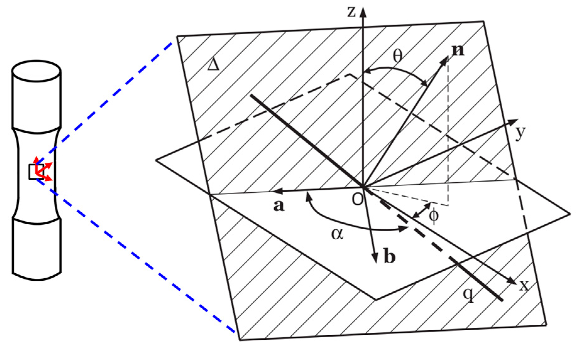
Figure 2.
Smith-Watson-Topper (SWT) parameter vs. correlation for GH4169 at 650 °C.

Figure 3.
Four normal stress-strain curves on principle strain plane for GH4169 at 650 °C.
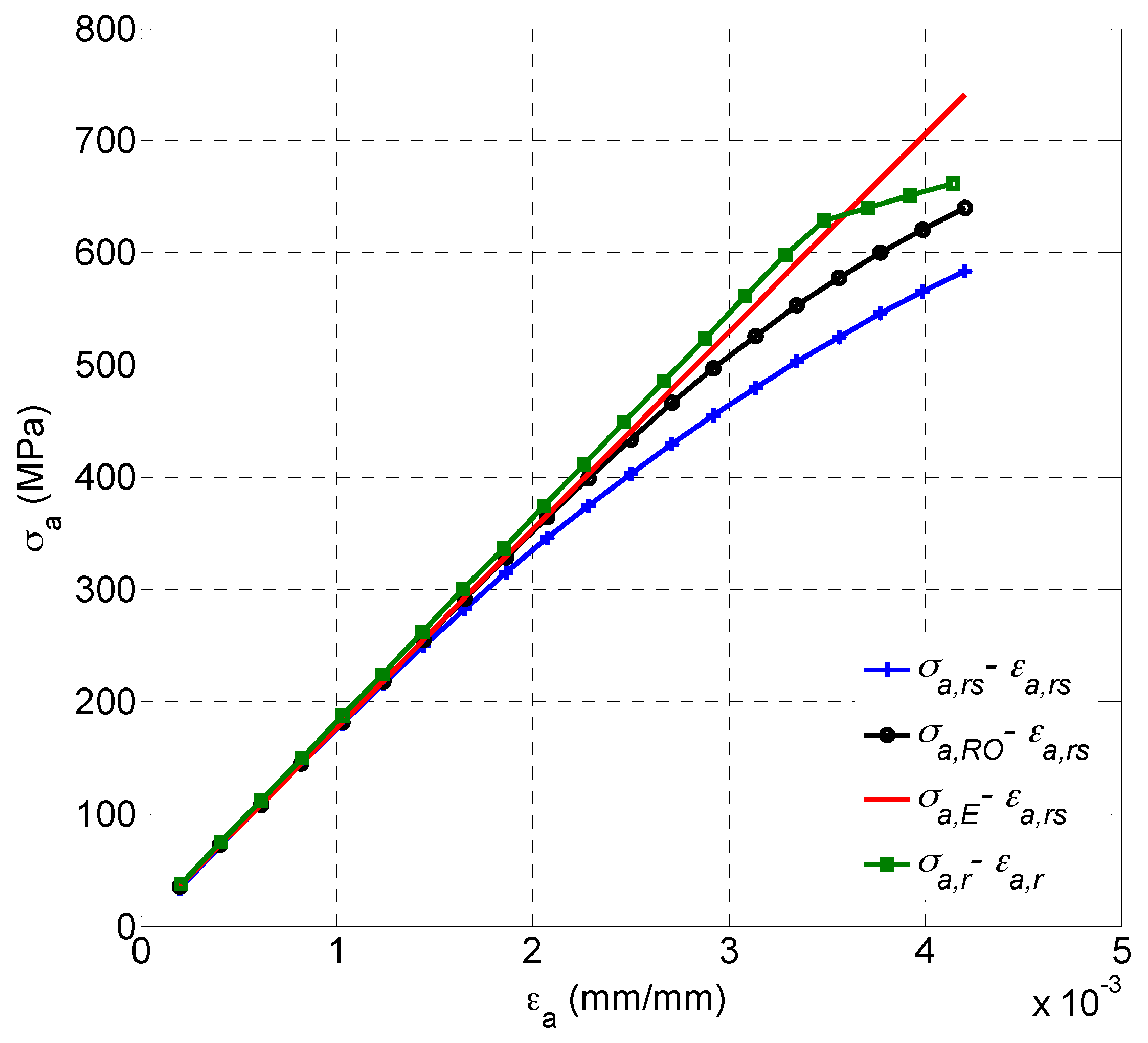
Figure 4.
Fatigue fracture mechanisms of the four models.

Figure 5.
Hysteresis loops of GH4169 at 650 °C: (a) Tension-compression and (b) Torsion.

Figure 6.
A comparison of uniaxial fatigue tested life and predicted life of three models for GH4169 at 650 °C.
Figure 6.
A comparison of uniaxial fatigue tested life and predicted life of three models for GH4169 at 650 °C.

Figure 7.
Box plot of model prediction errors for GH4169 under uniaxial loading at 650 °C.
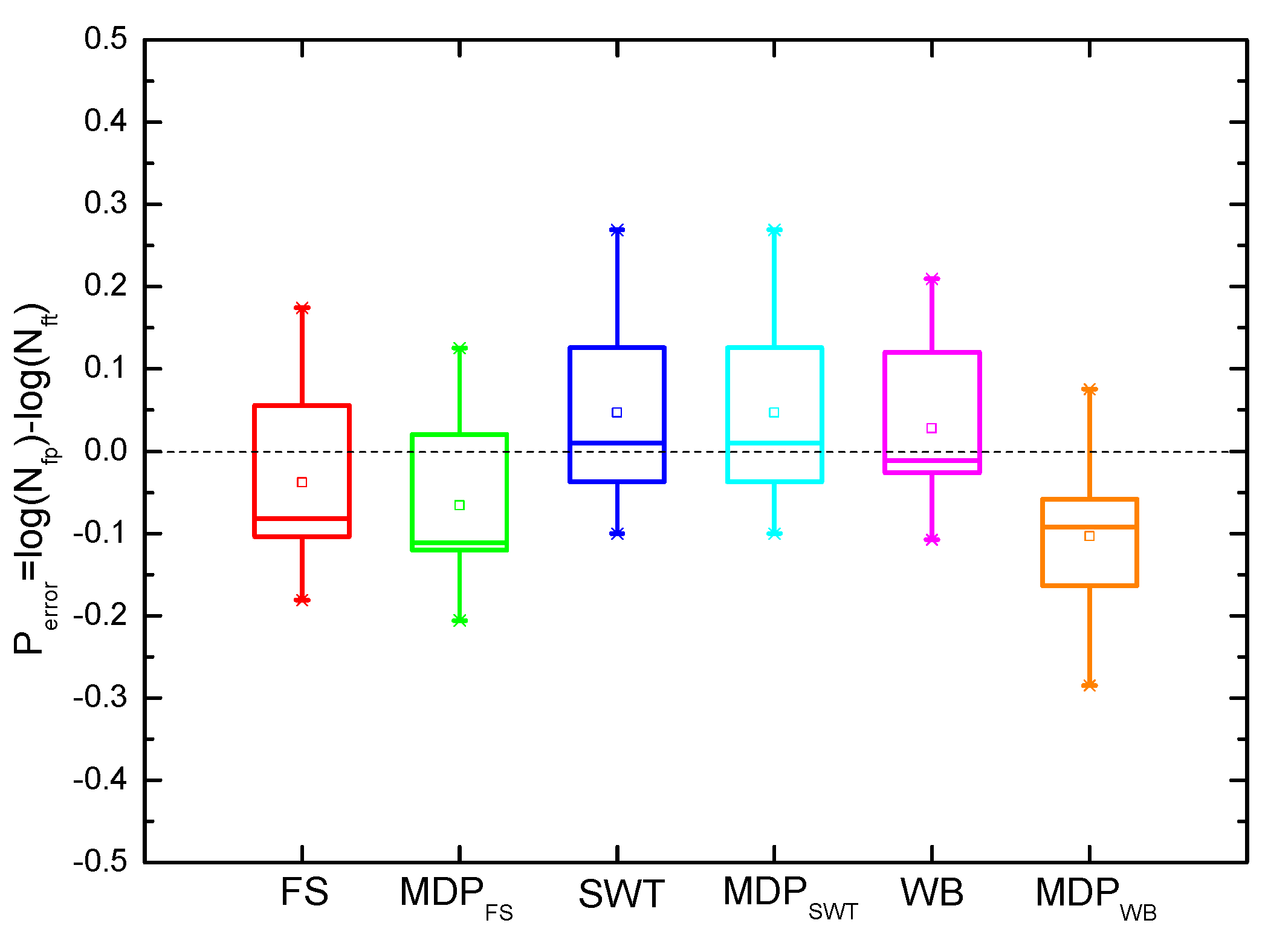
Figure 8.
Box plot of model prediction errors for GH4169 under multiaxial loading at 650 °C.

Figure 9.
A comparison of predicted life using (a) Fatemi-Socie (FS) and MDPFS parameters; (b) SWT and MDPSWT parameters; (c) Wang-Brown (WB) and MDPWB parameters and (d) SWT and energy-critical plane (ECP) parameters under multiaxial fatigue loadings.
Figure 9.
A comparison of predicted life using (a) Fatemi-Socie (FS) and MDPFS parameters; (b) SWT and MDPSWT parameters; (c) Wang-Brown (WB) and MDPWB parameters and (d) SWT and energy-critical plane (ECP) parameters under multiaxial fatigue loadings.

Figure 10.
FEA of a turbine disk-blade contact system: (a) the mesh; (b) von-Mises equivalent stress filed; and (c) equivalent plastic strain filed of turbine blade under the 0-Maximum-0 cycle.
Figure 10.
FEA of a turbine disk-blade contact system: (a) the mesh; (b) von-Mises equivalent stress filed; and (c) equivalent plastic strain filed of turbine blade under the 0-Maximum-0 cycle.

Figure 11.
Stress analysis of the element with critical plane.


Table 1.
Material properties of GH4169.
| T (°C) | E (GPa) | (MPa) | (MPa) | b | c | (MPa) | ||
|---|---|---|---|---|---|---|---|---|
| 650 | 182 | 626.4 | 1476 | 0.162 | −0.086 | −0.58 | 1933 | 0.1483 |
Table 2.
Multiaxial fatigue test data for GH4169 at 650 °C.
| No. | (°) | (%) | (%) | (MPa) | (MPa) | (cycles) |
|---|---|---|---|---|---|---|
| 1 | 45 | 0.354 | 0.420 | 601 | 347 | 4420 |
| 2 | 90 | 0.397 | 0.479 | 679 | 434 | 5665 |
| 3 | 0 | 0.408 | 0.592 | 503 | 295 | 1544 |
| 4 | 45 | 0.524 | 0.745 | 658 | 560 | 722 |
| 5 | 45 | 0.553 | 0.813 | 691 | 436 | 295 |
| 6 | 90 | 0.548 | 0.833 | 762 | 475 | 436 |
| 7 | 90 | 0.586 | 0.838 | 801 | 506 | 563 |
| 8 | 0 | 0.546 | 0.884 | 584 | 301 | 458 |
| 9 | 45 | 0.704 | 1.090 | 793 | 477 | 171 |
| 10 | 45 | 0.701 | 1.160 | 757 | 492 | 260 |
| 11 | 90 | 0.783 | 1.330 | 899 | 607 | 121 |
| 12 * | 0 | 0.54 | 0.896 | 745 | 317 | 338 |
| 13 * | 0 | 0.536 | 0.945 | 642 | 401 | 161 |
| 14 * | 0 | 0.427 | 0.633 | 637 | 268 | 1108 |
| 15 * | 0 | 0.448 | 0.709 | 556 | 370 | 1370 |
| 16 * | 45 | 0.478 | 0.749 | 655 | 426 | 1048 |
| 17 * | 45 | 0.625 | 1.000 | 648 | 435 | 222 |
| 18 * | 90 | 0.613 | 1.010 | 838 | 527 | 529 |
Note: The specimen number with labeling * is under sine wave loading.
Table 3.
Comparison of model predicted blade life.
| Model | Evaluated Life (cycles) | ||
|---|---|---|---|
| 0-450r/s-0 | 230r/s-450r/s-230r/s | 431r/s-450r/s-431r/s | |
| WB | 993346 | 59560715 | > |
| MDPWB | 13481520 | 113213394 | > |
| FS | 360185 | 63404561 | > |
| MDPFS | 253996 | 53007514 | > |
| SWT | 71540 | 676766 | > |
| MDPSWT | 71540 | 676766 | > |
| ECP | 85932 | 936842 | > |
© 2017 by the authors. Licensee MDPI, Basel, Switzerland. This article is an open access article distributed under the terms and conditions of the Creative Commons Attribution (CC BY) license (http://creativecommons.org/licenses/by/4.0/).
Share and Cite
MDPI and ACS Style
Yu, Z.-Y.; Zhu, S.-P.; Liu, Q.; Liu, Y. A New Energy-Critical Plane Damage Parameter for Multiaxial Fatigue Life Prediction of Turbine Blades. Materials 2017, 10, 513. https://doi.org/10.3390/ma10050513
AMA Style
Yu Z-Y, Zhu S-P, Liu Q, Liu Y. A New Energy-Critical Plane Damage Parameter for Multiaxial Fatigue Life Prediction of Turbine Blades. Materials. 2017; 10(5):513. https://doi.org/10.3390/ma10050513
Chicago/Turabian StyleYu, Zheng-Yong, Shun-Peng Zhu, Qiang Liu, and Yunhan Liu. 2017. "A New Energy-Critical Plane Damage Parameter for Multiaxial Fatigue Life Prediction of Turbine Blades" Materials 10, no. 5: 513. https://doi.org/10.3390/ma10050513
Note that from the first issue of 2016, this journal uses article numbers instead of page numbers. See further details here.