
Marginal Accuracy and Internal Fit of 3-D Printing Laser-Sintered Co-Cr Alloy Copings

Abstract
:1. Introduction
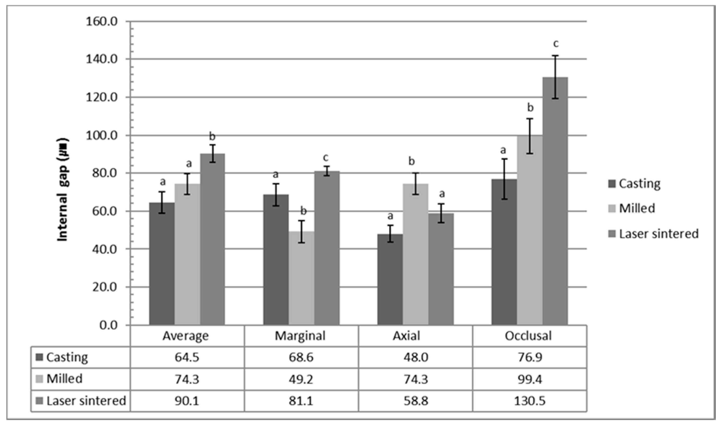
2. Results
3. Discussion
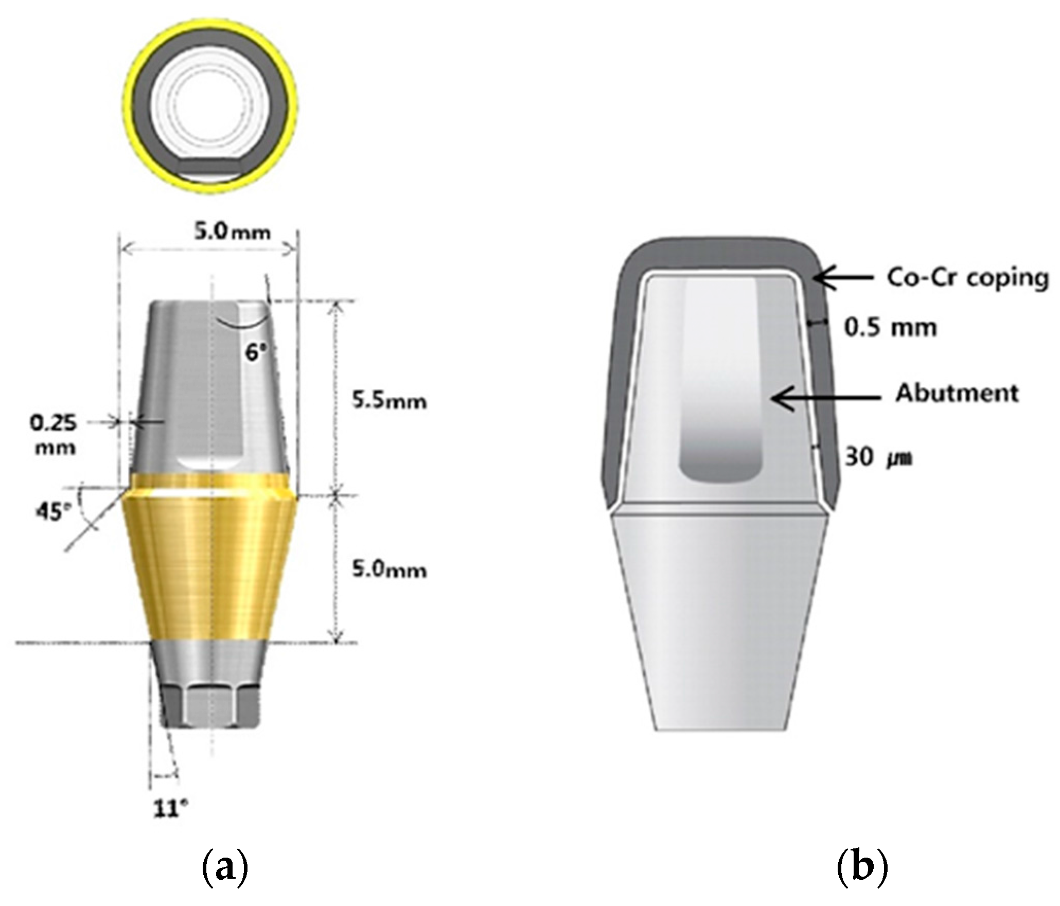
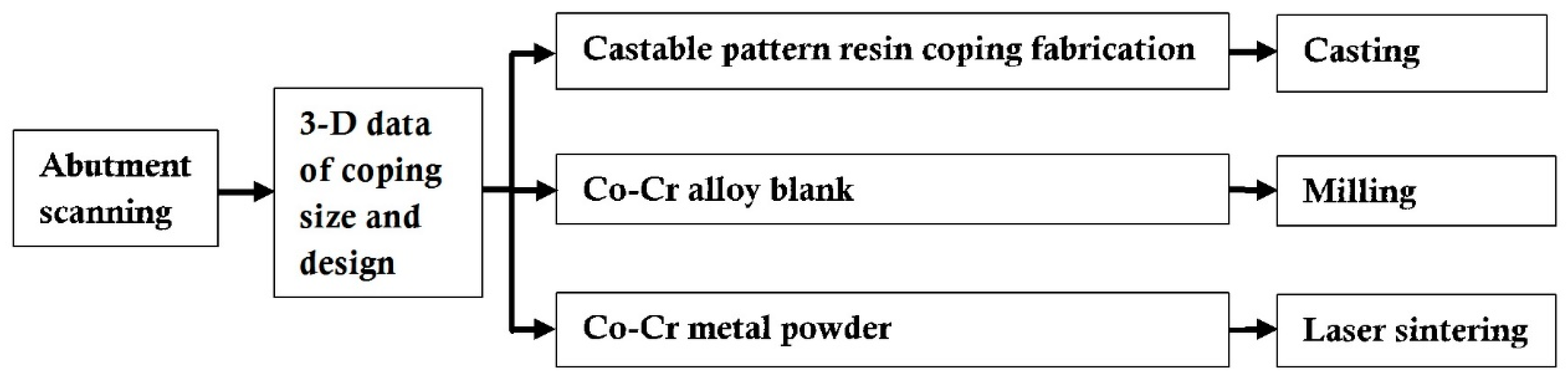
4. Materials and Methods
4.1. Material and Preparation of Specimens
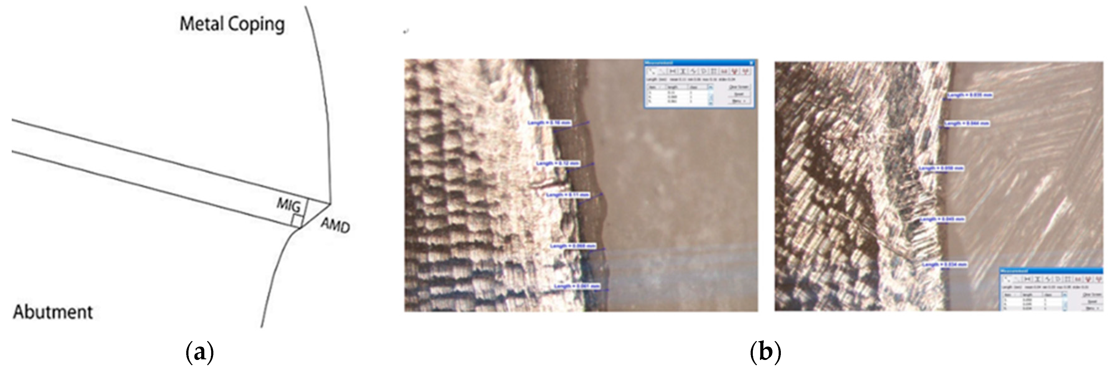
4.2. Fit Evaluations and Statistical Analysis
5. Conclusions
Acknowledgments
Author Contributions
Conflicts of Interest
References
- Wataha, J.C. Alloys for prosthodontic restorations. J. Prosthet. Dent. 2002, 87, 351–363. [Google Scholar] [CrossRef] [PubMed]
- Akova, T.; Ucar, Y.; TUKay, A.; Balkaya, M.C.; Brantley, W.A. ComParison of the bond strength of laser-sintered and cast base metal dental alloys to porcelain. Dent. Mater. 2008, 24, 1400–1404. [Google Scholar] [CrossRef] [PubMed]
- De Vasconcellos, L.G.; Buso, L.; Lombardo, G.H.; Souza, R.O.; Nogueira, L., Jr.; Bottino, M.A.; Ozcan, M. Opaque layer firing temperature and aging effect on the flexural strength of ceramic fused to the cobalt-chromium alloy. J. Prosthodont. 2010, 19, 471–477. [Google Scholar] [CrossRef] [PubMed]
- Viennot, S.; Dalard, F.; Lissac, M.; Grosgogeat, B. Corrosion resistance of cobalt-chromium and palladium-silver alloys used in fixed prosthetic restorations. Eur. J. Oral Sci. 2005, 113, 90–95. [Google Scholar] [CrossRef] [PubMed]
- Wu, Y.; Moser, J.B.; Jameson, L.M.; Malone, W.F. The effect of oxidation heat treatment of porcelain bond strength in selected base metal alloys. J. Prosthet. Dent. 1991, 66, 439–444. [Google Scholar] [CrossRef]
- Roach, M. Base metal alloys used for dental restorations and implants. Dent. Clin. N. Am. 2007, 51, 603–627. [Google Scholar] [CrossRef] [PubMed]
- Morris, H.F. Properties of cobalt-chromium metal ceramic alloys after heat treatment. J. Prosthet. Dent. 1990, 63, 426–433. [Google Scholar] [CrossRef]
- Takaichi, A.; Nakamoto, T.; Joko, N.; Nomura, N.; Tsutsumi, Y.; Migita, S.; Doi, H.; Kurosu, S.; Chiba, A.; Wakabayashi, N.; et al. Microstructures and mechanical properties of Co-29Cr-6Mo alloy fabricated by selective laser melting process for dental applications. J. Mech. Behav. Biomed. Mater. 2013, 21, 67–76. [Google Scholar] [CrossRef] [PubMed]
- Gelbard, S.; Aoskar, Y.; Zalkind, M.; Stern, N. Effect of impression materials and techniques on the marginal fit of metal castings. J. Prosthet. Dent. 1994, 71, 1–6. [Google Scholar] [CrossRef]
- Tan, P.L.; Gratton, D.G.; Diaz-Arnold, A.M.; Holmes, D.C. An in vitro comParison of vertical marginal gaps of CAD/CAM titanium and conventional cast restorations. J. Prosthodont. 2008, 17, 378–383. [Google Scholar] [CrossRef] [PubMed]
- Kim, K.B.; Kim, W.C.; Kim, H.Y.; Kim, J.H. An evaluation of marginal fit of three-unit fixed dental prostheses fabricated by direct metal laser sintering system. Dent. Mater. 2013, 29, e91–e96. [Google Scholar] [CrossRef] [PubMed]
- Fasbinder, D.J. Clinical performance of chairside CAD/CAM restorations. J. Am. Dent. Assoc. 2006, 137, 22S–31S. [Google Scholar] [CrossRef] [PubMed]
- Miyazaki, T.; Hotta, Y.; Kunii, J.; Kuriyama, S.; Tamaki, Y. A review of dental CAD/CAM: Current status and future perspectives from 20 years of experience. Dent. Mater. J. 2009, 28, 44–56. [Google Scholar] [CrossRef] [PubMed]
- Holst, S.; Persson, A.; Wichmann, M.; Karl, M. Digitizing implant position locators on master casts: Comparison of a noncontact scanner and a contact-probe scanner. Int. J. Oral Maxillofac. Implants 2012, 27, 29–35. [Google Scholar] [PubMed]
- Ucar, Y.; Akova, T.; Akyil, M.S.; Brantley, W.A. Internal fit evaluation of crowns prepared using a new dental crown fabrication technique: Laser-sintered Co-Cr crowns. J. Prosthet. Dent. 2009, 102, 253–259. [Google Scholar] [CrossRef]
- Chan, D.C.; Chung, A.K.; Haines, J.; Yau, E.H.; Kuo, C.C. The accuracy of optical scanning: Influence of convergence and die preparation. Oper. Dent. 2011, 36, 486–491. [Google Scholar] [CrossRef] [PubMed]
- Park, J.K.; Lee, W.S.; Kim, H.Y.; Kim, W.C.; Kim, J.H. Accuracy evaluation of metal copings fabricated by computer-aided milling and direct metal laser sintering systems. J. Adv. Prosthodont. 2015, 7, 122–128. [Google Scholar] [CrossRef] [PubMed]
- Suleiman, S.H.; Vult von Steyern, P. Fracture strength of porcelain fused to metal crowns made of cast, milled or laser-sintered cobalt-chromium. Acta Odontol. Scand. 2013, 71, 1280–1289. [Google Scholar] [CrossRef] [PubMed]
- Al Jabbari, Y.S.; KoutsoUKis, T.; Barmpagadaki, X.; Zinelis, S. Metallurgical and interfacial characterization of PFM Co-Cr dental alloys fabricated via casting, milling or selective laser melting. Dent. Mater. 2014, 30, e79–e88. [Google Scholar] [CrossRef] [PubMed]
- Xin, X.Z.; Chen, J.; Xiang, N.; Wei, B. Surface properties and corrosion behavior of Co-Cr alloy fabricated with selective laser melting technique. Cell Biochem. Biophys. 2013, 67, 983–990. [Google Scholar] [CrossRef] [PubMed]
- Quante, K.; Ludwig, K.; Kern, M. Marginal and internal fit of metal-ceramic crowns fabricated with a new laser melting technology. Dent. Mater. 2008, 24, 1311–1315. [Google Scholar] [CrossRef] [PubMed]
- Choi, Y.J.; Heo, S.J.; Kim, S.K.; Ahn, J.S.; Park, D.S. ComParison of the mechanical properties and microstructures of the fractured surface for Co-Cr alloy fabricated by the conventional cast, 3-D printing laser-sintered and CAD/CAM milled techniques. J. Korean Acad. Prosthodont. 2014, 52, 67–73. [Google Scholar] [CrossRef]
- Sorensen, S.E.; Larsen, I.B.; Jorgensen, K.D. Gingival and alveolar bone reaction to the marginal fit of subgingival crown margins. Scand. J. Dent. Res. 1986, 94, 109–114. [Google Scholar] [CrossRef] [PubMed]
- Felton, D.A.; Kanoy, B.E.; Bayne, S.C.; Wirthman, G.P. Effect of in vivo crown margin discrepancies on periodontal health. J. Prosthet. Dent. 1991, 65, 357–364. [Google Scholar] [CrossRef]
- Jacobs, M.S.; Windeler, A.S. An investigation of dental luting cement solubility as a function of the marginal gap. J. Prosthet. Dent. 1991, 65, 436–442. [Google Scholar] [CrossRef]
- Gavelis, J.R.; Morency, J.D.; Riley, E.D.; Sozio, R.B. The effect of various finish line preparations on the marginal seal and occlUSAl seat of full crown preparations. J. Prosthet. Dent. 1981, 45, 138–145. [Google Scholar] [CrossRef]
- Lindhe, J.; Berglundh, T.; Ericsson, I.; Liljenberg, B.; Marinello, C. Experimental breakdown of peri-implant and periodontal tissues. A study in the beagle dog. Clin. Oral Implants Res. 1992, 3, 9–16. [Google Scholar] [CrossRef] [PubMed]
- McLean, J.W.; von Fraunhofer, J.A. The estimation of cement film thickness by an in vivo technique. Br. Dent. J. 1971, 131, 107–111. [Google Scholar] [CrossRef] [PubMed]
- Kashani, H.G.; Khera, S.C.; Gulker, I.A. The effects of bevel angulation on marginal integrity. J. Am. Dent. Assoc. 1981, 103, 882–885. [Google Scholar] [CrossRef] [PubMed]
- Jesus Suarez, M.; Lozano, J.F.; Paz Salido, M.; Martinez, F. Marginal fit of titanium metal-ceramic crowns. Int. J. Prosthodont. 2005, 18, 390–391. [Google Scholar] [PubMed]
- Blackman, R.; Baez, R.; Barghi, N. Marginal accuracy and geometry of cast titanium copings. J. Prosthet. Dent. 1992, 67, 435–440. [Google Scholar] [CrossRef]
- Christensen, G.J. The marginal fit of gold inlay castings. J. Prosthet. Dent. 1966, 16, 297–305. [Google Scholar] [CrossRef]
- Han, H.S.; Yang, H.S.; Lim, H.P.; Park, Y.J. Marginal accuracy and internal fit of machine-milled and cast titanium crowns. J. Prosthet. Dent. 2011, 106, 191–197. [Google Scholar] [CrossRef]
- Ortorp, A.; Jonsson, D.; Mouhsen, A.; von Steyern, P.V. The fit of cobalt-chromium three-unit fixed dental prostheses fabricated with four different techniques: A comparative in vitro study. Dent. Mater. 2011, 27, 356–363. [Google Scholar] [CrossRef] [PubMed]
- Witkowski, S.; Komine, F.; Gerds, T. Marginal accuracy of titanium copings fabricated by casting and CAD/CAM techniques. J. Prosthet. Dent. 2006, 96, 47–52. [Google Scholar] [CrossRef] [PubMed]
- Alghazzawi, T.F.; Liu, P.R.; Essig, M.E. The effect of different fabrication steps on the marginal adaptation of two types of glass-infiltrated ceramic crown copings fabricated by CAD/CAM technology. J. Prosthodont. 2012, 21, 167–172. [Google Scholar] [CrossRef] [PubMed]
- Kokubo, Y.; Nagayama, Y.; Tsumita, M.; Ohkubo, C.; Fukushima, S.; von Steyern, P.V. Clinical marginal and internal gaps of In-Ceram crowns fabricated using the GN-I system. J. Oral Rehabil. 2005, 32, 753–758. [Google Scholar] [CrossRef] [PubMed]
- Nakamura, T.; Dei, N.; Kojima, T.; Wakabayashi, K. Marginal and internal fit of Cerec 3 CAD/CAM all-ceramic crowns. Int. J. Prosthodont. 2003, 16, 244–248. [Google Scholar] [PubMed]
- May, K.B.; Russell, M.M.; Razzoog, M.E.; Lang, B.R. The precision of fit: The Procera AllCeram crown. J. Prosthet. Dent. 1998, 80, 394–404. [Google Scholar] [CrossRef]
- Bindl, A.; Mormann, W.H. Marginal and internal fit of all-ceramic CAD/CAM crown-copings on chamfer preparations. J. Oral Rehabil. 2005, 32, 441–447. [Google Scholar] [CrossRef] [PubMed]
- Oyague, R.C.; Turrion, A.S.; Toledano, M.; Monticelli, F.; Osorio, R. In vitro vertical misfit evaluation of cast frameworks for cement-retained implant-supported partial prostheses. J. Dent. 2009, 37, 52–58. [Google Scholar] [CrossRef] [PubMed]
- Wang, C.J.; Millstein, P.L.; Nathanson, D. Effects of cement, cement space, marginal design, seating aid materials, and seating force on crown cementation. J. Prosthet. Dent. 1992, 67, 786–790. [Google Scholar] [CrossRef]
- Sulaiman, F.; Chain, J.; Jameson, L.M.; Wozniak, W.T. A comParison of the marginal fit of In-Ceram, IPS Empress, and Procera crowns. Int. J. Prosthodont. 1997, 10, 478–484. [Google Scholar] [PubMed]
- Wakabayashi, K.; Sohmura, T.; Nakamura, T.; Kojima, T.; Kinuta, S.; Takahashi, J.; Yatani, H. New evaluation method by microfocus radiograph CT for 3D assessment of internal adaptation of all-ceramic crowns. Dent. Mater. J. 2005, 24, 362–367. [Google Scholar] [CrossRef] [PubMed]
- Gonzalo, E.; Suarez, M.J.; Serrano, B.; Lozano, J.F. A comParison of the marginal vertical discrepancies of zirconium and metal ceramic posterior fixed dental prostheses before and after cementation. J. Prosthet. Dent. 2009, 102, 378–384. [Google Scholar] [CrossRef]
- Kohorst, P.; Brinkmann, H.; Li, J.; Borchers, L.; Stiesch, M. Marginal accuracy of four-unit zirconia fixed dental prostheses fabricated using different computer-aided design/computer-aided manufacturing systems. Eur. J. Oral Sci. 2009, 117, 319–325. [Google Scholar] [CrossRef] [PubMed]
- Holmes, J.R.; Bayne, S.C.; Holland, G.A.; Sulik, W.D. Considerations in the measurement of marginal fit. J. Prosthet. Dent. 1989, 62, 405–408. [Google Scholar] [CrossRef]
- Groten, M.; Girthofer, S.; Probster, L. Marginal fit consistency of copy-milled all-ceramic crowns during fabrication by light and scanning electron microscopic analysis in vitro. J. Oral Rehabil. 1997, 24, 871–881. [Google Scholar] [CrossRef] [PubMed]
- Yeo, I.S.; Yang, J.H.; Lee, J.B. In vitro marginal fit of three all-ceramic crown systems. J. Prosthet. Dent. 2003, 90, 459–464. [Google Scholar] [CrossRef] [PubMed]
- Ardekani, K.T.; Ahangari, A.H.; Farahi, L. Marginal and internal fit of CAD/CAM and slip-cast made zirconia copings. J. Dent. Res. Dent. Clin. Dent. Prospect. 2012, 6, 42–48. [Google Scholar]
- Rinke, S.; Huls, A.; Jahn, L. Marginal accuracy and fracture strength of conventional and copy-milled all-ceramic crowns. Int. J. Prosthodont. 1995, 8, 303–310. [Google Scholar] [PubMed]
- Zeng, L.; Zhang, Y.; Liu, Z.; Wei, B. Effects of repeated firing on the marginal accuracy of Co-Cr copings fabricated by selective laser melting. J. Prosthet. Dent. 2015, 113, 135–139. [Google Scholar] [CrossRef] [PubMed]
- Barucca, G.; Santecchia, E.; Majni, G.; Girardin, E.; Bassoli, E.; Denti, L.; Gatto, A.; Iuliano, L.; Moskalewicz, T.; Mengucci, P. Structural characterization of biomedical Co-Cr-Mo components produced by direct metal laser sintering. Mater. Sci. Eng. C Mater. Biol. Appl. 2015, 48, 263–269. [Google Scholar] [CrossRef] [PubMed] [Green Version]
- Mengucci, P.; Barucca, G.; Gatto, A.; Bassoli, E.; Denti, L.; Fiori, F.; Girardin, E.; Bastianoni, P.; Rutkowski, B.; Czyrska-Filemonowicz, A. Effects of thermal treatments on microstructure and mechanical properties of a Co-Cr-Mo-W biomedical alloy produced by laser sintering. J. Mech. Behav. Biomed. Mater. 2016, 60, 106–117. [Google Scholar] [CrossRef] [PubMed]
- Matta, R.E.; Schmitt, J.; Wichmann, M.; Holst, S. Circumferential fit assessment of CAD/CAM single crowns—A pilot investigation on a new virtual analytical protocol. Quintessence Int. 2012, 43, 801–809. [Google Scholar] [PubMed]
- Martinez-Rus, F.; Suarez, M.J.; Rivera, B.; Pradies, G. Evaluation of the absolute marginal discrepancy of zirconia-based ceramic copings. J. Prosthet. Dent. 2011, 105, 108–114. [Google Scholar] [CrossRef]
- Baig, M.R.; Tan, K.B.; Nicholls, J.I. Evaluation of the marginal fit of a zirconia ceramic computer-aided machined (CAM) crown system. J. Prosthet. Dent. 2010, 104, 216–227. [Google Scholar] [CrossRef]


| Group | Mean (g) | SD |
|---|---|---|
| Casting | 0.006 a | 0.001 |
| CAD/CAM milled | 0.007 b | 0.001 |
| 3-D laser sintered | 0.007 b | 0.001 |
| Group | Mean (µm) | SD |
|---|---|---|
| Casting | 38.2 a | 6.2 |
| CAD/CAM milled | 51.5 b | 7.0 |
| 3-D laser sintered | 72.5 c | 12.4 |
| Group | Weight | Marginal Gap | Average Internal Fit |
|---|---|---|---|
| Weight | 1 | - | - |
| Marginal Gap | 0.257 | 1 | - |
| Average Internal Fit | 0.008 | 0.625 | 1 |
| Alloys | Co | Cr | Mo | W | Si | Fe | Mn |
|---|---|---|---|---|---|---|---|
| Casting | 63 | 28 | 5.5 | <3.5 | |||
| CAD/CAM Milled | 59 | 25 | 3.5 | 9.5 | 1.0 | <1.5 | |
| 3-D Lasersintered | 63.8 | 24.7 | 5.1 | 5.4 | 1.0 | <0.5 | <0.1 |
© 2017 by the authors. Licensee MDPI, Basel, Switzerland. This article is an open access article distributed under the terms and conditions of the Creative Commons Attribution (CC BY) license ( http://creativecommons.org/licenses/by/4.0/).
Share and Cite
Kim, M.-J.; Choi, Y.-J.; Kim, S.-K.; Heo, S.-J.; Koak, J.-Y. Marginal Accuracy and Internal Fit of 3-D Printing Laser-Sintered Co-Cr Alloy Copings. Materials 2017, 10, 93. https://doi.org/10.3390/ma10010093
Kim M-J, Choi Y-J, Kim S-K, Heo S-J, Koak J-Y. Marginal Accuracy and Internal Fit of 3-D Printing Laser-Sintered Co-Cr Alloy Copings. Materials. 2017; 10(1):93. https://doi.org/10.3390/ma10010093
Chicago/Turabian StyleKim, Myung-Joo, Yun-Jung Choi, Seong-Kyun Kim, Seong-Joo Heo, and Jai-Young Koak. 2017. "Marginal Accuracy and Internal Fit of 3-D Printing Laser-Sintered Co-Cr Alloy Copings" Materials 10, no. 1: 93. https://doi.org/10.3390/ma10010093