
Effect of Photoanode Design on the Photoelectrochemical Performance of Dye-Sensitized Solar Cells Based on SnO2 Nanocomposite

Abstract
:1. Introduction
2. Results and Discussion
3. Materials and Methods
4. Conclusions
Acknowledgments
Author Contributions
Conflicts of Interest
References
- Bella, F.; Galliano, S.; Gerbaldi, C.; Viscardi, G. Cobalt-based electrolyte for dye-sensitized solar cells: Recent advances towards stable devices. Energies 2016, 9, 384. [Google Scholar] [CrossRef]
- Raj, A.C.; Prasanth, R. A critical review of recent developments in nanomaterials for photoelectrodes in dye sensitized solar cells. J. Power Sources 2016, 317, 120–132. [Google Scholar] [CrossRef]
- Gerosa, M.; Sacco, A.; Scalia, A.; Bella, F.; Chiodoni, A.; Quaglio, M.; Tresso, E.; Bianco, S. Toward totally flexible dye-sensitized solar cells based on titanium grids and polymeric electrolyte. IEEE J. Photovolt. 2016, 6, 498–505. [Google Scholar] [CrossRef]
- Bella, F.; Leftheriotis, G.; Griffini, G.; Syrrokostas, G.; Turri, S.; Gratzel, M.; Gerbaldi, C. A new design paradigm for smart windows: Photocurable polymer for quasi-solid photoelectrochromic devices with excellent long-term stability under real outdoor operating conditions. Adv. Funct. Mater. 2016, 26. [Google Scholar] [CrossRef]
- Yella, A.; Lee, H.W.; Tsao, H.N.; Yi, C.; Chandiran, A.K.; Nazeeruddin, M.K.; Diau, E.W.G.; Yeh, C.Y.; Zakeeruddin, S.M.; Grätzel, M. Porphyrin-sensitized solar cells with cobalt (II/III)-based redox electrolyte 719 exceed 12 percent efficiency. Science 2011, 334, 629–634. [Google Scholar] [CrossRef] [PubMed]
- Venditti, I.; Barbero, N.; Russo, M.V.; Di Carlo, A.; Decker, F.; Fratoddi, I.; Barolo, C.; Dini, D. Electrodeposited ZnO with squaraine sensitizers as photoactive anode of DSCs. Mater. Res. Exp. 2014, 1. [Google Scholar] [CrossRef]
- Lee, J.H.; Park, N.G.; Shin, Y.J. Nano-grain SnO2 electrodes for high conversion efficiency SnO2-DSSC. Sol. Energy Mater. Sol. Cells 2011, 95, 179–183. [Google Scholar] [CrossRef]
- Tan, B.; Toman, E.; Li, Y.; Wu, Y. Zinc stannate (Zn2SnO4) dye-sensitized solar cells. J. Am. Chem. Soc. 2007, 129, 4162–4163. [Google Scholar] [CrossRef] [PubMed]
- Elumalai, N.K.; Jose, R.; Archana, P.S.; Chellappan, V.; Ramakrishna, S. Charge transport through electrospun SnO2 nanoflowers and nanofibers: Role of surface trap density on electron transport dynamics. J. Phys. Chem. C 2012, 116, 22112–22120. [Google Scholar] [CrossRef]
- Fonstad, C.G.; Rediker, R.H. Electrical properties of high quality stannic oxide crystals. J. Appl. Phys. 1971, 42, 2911–2918. [Google Scholar] [CrossRef]
- Lupan, O.; Chowa, L.; Chaic, G.; Schultea, A.; Parka, S.; Heinrich, H. A rapid hydrothermal synthesis of rutile SnO2 nanowires. Mater. Sci. Eng. B 2009, 157, 101–104. [Google Scholar] [CrossRef]
- Bhande, S.S.; Taur, G.A.; Shaikh, A.V.; Joo, O.S.; Sung, M.M.; Mane, R.S.; Ghule, A.V.; Han, S.H. Structural analysis and dye-sensitized solar cell application of electrodeposited tin oxide nanoparticles. Mater. Lett. 2012, 79, 29–31. [Google Scholar] [CrossRef]
- Liu, M.; Yang, J.; Feng, S.; Zhu, H.; Zhang, J.; Li, G.; Peng, J. Composite photoanodes of Zn2SnO4 nanoparticles modified SnO2 hierarchical microspheres for dye-sensitized solar cells. Mater. Lett. 2012, 76, 215–218. [Google Scholar] [CrossRef]
- Milan, R.; Selopal, G.S.; Epifani, M.; Natile, M.M.; Sberveglieri, G.; Vomiero, A.; Concina, I. ZnO@SnO2 engineered composite photoanodes for dye sensitized solar cells. Sci. Rep. 2015, 5, 14523. [Google Scholar] [CrossRef] [PubMed]
- Tennakone, K.; Bandara, J.; Bandaranayake, P.K.M.; Kumara, G.R.A.; Konno, A. Enhanced efficiency of a dye-sensitized solar cell made from MgO-coated nanocrystalline SnO2. Jpn. J. Appl. Phys. 2001, 40, L732–L734. [Google Scholar] [CrossRef]
- Look, D.C.; Reynolds, D.C.; Sizelove, J.R.; Jones, R.L.; Litton, C.W.; Cantwell, G.; Harsch, W.C. Electrical properties of bulk ZnO. Solid State Commun. 1998, 105, 399–401. [Google Scholar] [CrossRef]
- Wang, H.; Bhattacharjee, R.; Hung, I.M.; Li, L.; Zeng, R. Material characteristics and electrochemical performance of Sn-doped ZnO spherical-particle photoanode for dye-sensitized solar cells. Electrochim. Acta 2013, 111, 797–801. [Google Scholar] [CrossRef]
- Polat, I.; Yılmaz, S.; Bacaksız, E.; Atasoy, Y.; Tomakin, M. Synthesis and fabrication of Mg-doped ZnO-based dye-synthesized solar cells. J. Mater. Sci. Mater. Electron. 2014, 25, 3173–3178. [Google Scholar] [CrossRef]
- Bhattacharjee, R.; Hung, I.M. Effect of different concentration Li-doping on the morphology, defect and photovoltaic performance of Li-ZnO nanofibers in the dye-sensitized solar cells. Mater. Chem. Phys. 2014, 143, 693–701. [Google Scholar] [CrossRef]
- Lai, F.I.; Yang, J.F.; Kuo, S.Y. Efficiency enhancement of dye-sensitized solar cells’ performance with ZnO nanorods grown by low-temperature hydrothermal reaction. Materials 2015, 8, 8860–8867. [Google Scholar] [CrossRef]
- EI-Morshedi, N.; Alzahrani, I.; Kizibash, N.A.; Al-Fayez, H.A.A. Toxic effect of zinc oxide nanoparticles on some organs in experimental male wistar rats. Int. J. Adv. Res. 2014, 2, 907–915. [Google Scholar]
- Zhang, X.Q.; Yin, L.H.; Tang, M.; Pu, Y.P. ZnO, TiO2, SiO2, and Al2O3 nanoparticles induced toxic effects on human fetal lung fibroblasts. Biomed. Environ. Sci. 2011, 24, 661–669. [Google Scholar] [PubMed]
- Cox, A.; Venkatachalam, P.; Sahi, S.; Sharma, N. Silver and titanium dioxide nanoparticle toxicity in plants: A review of current research. Plant Physiol. Biochem. 2016, 107, 147–163. [Google Scholar] [CrossRef] [PubMed]
- Bhattacharjee, R.; Hung, I.M. A SnO2 and ZnO nanocomposite photoanodes in dye-sensitized solar cells. Electrochem Solid State Lett. 2013, 2, Q101–Q104. [Google Scholar] [CrossRef]
- Snaith, H.J.; Ducati, C. SnO2-based dye-sensitized hybrid solar cells exhibiting near unity absorbed photon-to-electron conversion efficiency. Nano Lett. 2010, 10, 1259–1265. [Google Scholar] [CrossRef] [PubMed]
- Frank, A.J.; Kopidakis, N.; Lagemaat, J.V.D. Electrons in nanostructured TiO2 solar cells: Transport, recombination and photovoltaic properties. Coord. Chem. Rev. 2004, 248, 1165–1179. [Google Scholar] [CrossRef]
- Tennakone, K.; Jayaweera, P.V.V.; Bandaranayake, P.K.M. Dye-sensitized photoelectrochemical and solid-state solar cells: Charge separation, transport and recombination mechanisms. J. Photochem. Photobiol. A Chem. 2003, 158, 125–130. [Google Scholar] [CrossRef]
- Ito, S.; Liska, P.; Comte, P.; Charvet, R.; Pechy, P.; Bach, U.; Schmidt-Mende, L.; Zakeeruddin, S.M.; Kay, A.; Nazeeruddin, M.K.; et al. Control of dark current in photoelectrochemical (TiO2/I−-I3−) and dye-sensitized solar cells. Chem. Commun. 2005, 34, 4351–4353. [Google Scholar] [CrossRef] [PubMed]
- Hu, F.Y.; Xia, Y.J.; Guan, Z.S.; Yin, X.; He, T. Low temperature fabrication of ZnO compact layer for high performance plastic dye-sensitized ZnO solar cells. Electrochim. Acta 2012, 69, 97–101. [Google Scholar] [CrossRef]
- Tan, B.; Wu, Y. Dye-sensitized solar cells based on anatase TiO2 nanoparticle/nanowire composites. J. Phys. Chem. B 2006, 110, 15932–15938. [Google Scholar] [CrossRef] [PubMed]
- Grätzel, M. Photoelectrochemical cells. Nature 2001, 414, 338–344. [Google Scholar] [CrossRef] [PubMed]
- Bisquert, J.; Zaban, A.; Greenshtein, M.; Mora-Seró, I. Determination of rate constants for charge transfer and the distribution of semiconductor and electrolyte electronic energy levels in dye-sensitized solar cells by open circuit photovoltage decay method. J. Am. Chem. Soc. 2004, 126, 13550–13559. [Google Scholar] [CrossRef] [PubMed]
- Chi, C.F.; Cho, H.W.; Teng, H.; Chuang, C.Y.; Chang, Y.M.; Hsu, Y.J.; Lee, Y.L. Energy level alignment, energy level alignment, electron injection, and charge recombination characteristics in CdS/CdSe cosensitized TiO2 photoelectrode. Appl. Phys. Lett. 2011, 98. [Google Scholar] [CrossRef]
- Santiago, F.F.; Canadas, J.G.; Palomares, E.; Clifford, J.N.; Haque, S.A.; Durrant, J.R.; Belmonte, G.G.; Bisquert, J. The origin of slow electron recombination processes in dye-sensitized solar cells with alumina barrier coatings. J. Appl. Phys. 2004, 96, 6903–6907. [Google Scholar] [CrossRef]
- Saito, M.; Fujihara, S. Large photocurrent generation in dye-sensitized ZnO solar cells. Energy Environ. Sci. 2008, 1, 280–283. [Google Scholar] [CrossRef]
- Dong, H.P.; Wang, L.D.; Gao, R.; Ma, B.B.; Qiu, Y. Constructing nanorod-nanoparticles hierarchical structure at low temperature as photoanodes for dye-sensitized solar cells: Combining relatively fast electron transport and high dye-loading together. J. Mater. Chem. 2011, 21, 19389–19394. [Google Scholar] [CrossRef]
- Guerin, V.M.; Magne, C.; Pauporte, T.; Le Bahers, T.; Rathousky, J. Electrodeposited nanoporous versus nanoparticulate ZnO films of similar roughness for dye-sensitized solar cell applications. ACS Appl. Mater. Interfaces 2010, 2, 3677–3685. [Google Scholar] [CrossRef] [PubMed]
- Liu, Y.; Sun, X.; Tai, Q.; Hu, H.; Chen, B.; Huang, N.; Sebo, B.; Zhao, X.Z. Efficiency enhancement in dye-sensitized solar cells by interfacial modification of conducting glass/mesoporous TiO2 using a novel ZnO compact blocking film. J. Power Sources 2011, 196, 475–481. [Google Scholar] [CrossRef]
- Adachi, M.; Sakamoto, M.; Jiu, J.; Ogata, Y.; Isoda, S. Determination of parameters of electron transport in dye-sensitized solar cells using electrochemical impedance spectroscopy. J. Phys. Chem. B 2006, 110, 13872–13880. [Google Scholar] [CrossRef] [PubMed]
- Wang, M.; Chen, P.; Humphry-Baker, R.; Zakeeruddin, S.M.; Gratzel, M. The influence of charge transport and recombination on the performance of dye-sensitized solar cells. Chemphyschem 2009, 10, 290–299. [Google Scholar] [CrossRef] [PubMed]
- Supothina, S.; Rattanakam, R.; Vichaphund, S.; Thavorniti, P. Effect of synthesis condition on morphology and yield of hydrothermally grown SnO2 nanorod clusters. J. Eur. Ceram. Soc. 2011, 31, 2453–2458. [Google Scholar] [CrossRef]
- Zhang, Q.; Dandeneau, C.S.; Candelaria, S.; Liu, D.; Garcia, B.B.; Zhou, X.; Jeong, Y.H.; Cao, G. Effects of lithium ions on dye-sensitized ZnO aggregate solar cells. Chem. Mater. 2010, 22, 2427–2433. [Google Scholar] [CrossRef]


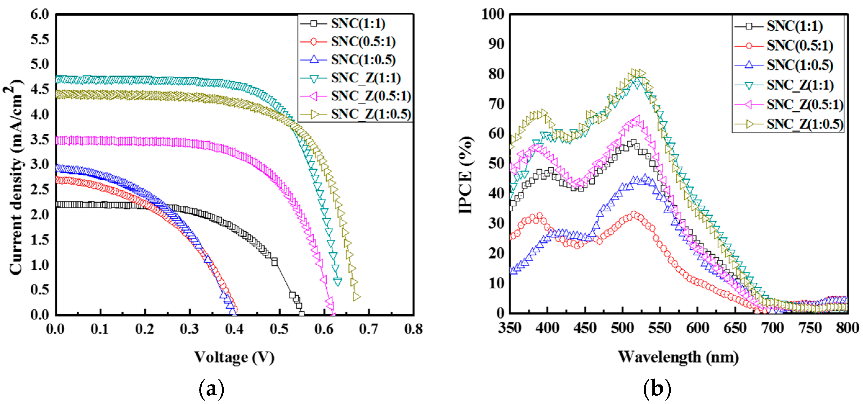
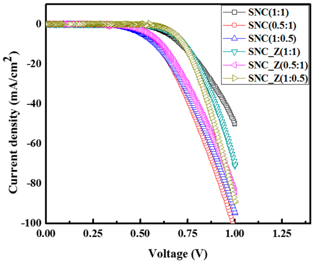
| Sample | Jsc (mA/cm2) | Voc (mV) | FF (%) | IPCE (%) | η (%) |
|---|---|---|---|---|---|
| SNC (1:1) | 2.21 | 549.93 | 57.38 | 57.3 | 0.70 |
| SNC (1:0.5) | 2.91 | 395.13 | 45.92 | 44.4 | 0.65 |
| SNC (0.5:1) | 2.72 | 400.07 | 45.00 | 33.0 | 0.49 |
| SNC_Z (1:1) | 4.73 | 630.15 | 69.33 | 78.5 | 2.06 |
| SNC_Z (1:0.5) | 3.57 | 670.16 | 68.56 | 80.6 | 2.02 |
| SNC_Z (0.5:1) | 3.49 | 615.08 | 63.21 | 63.9 | 1.36 |
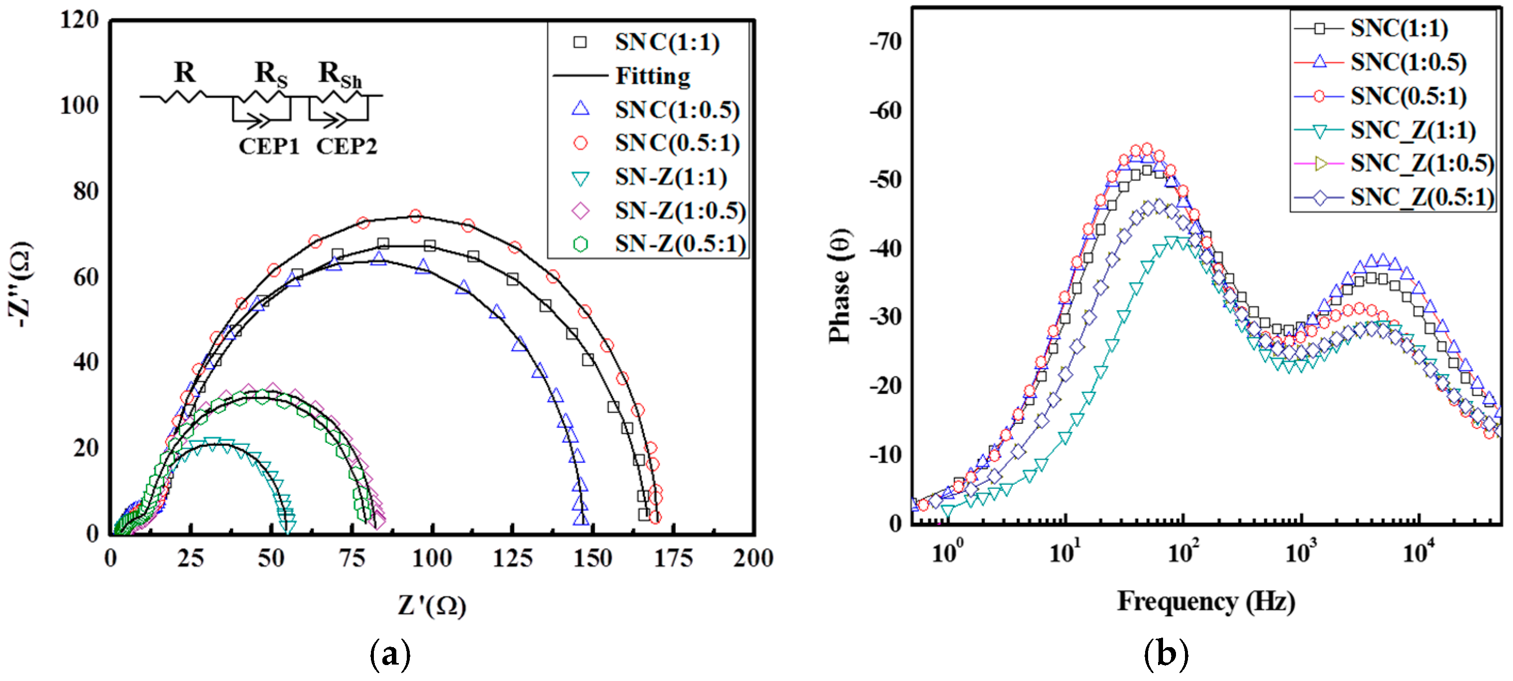
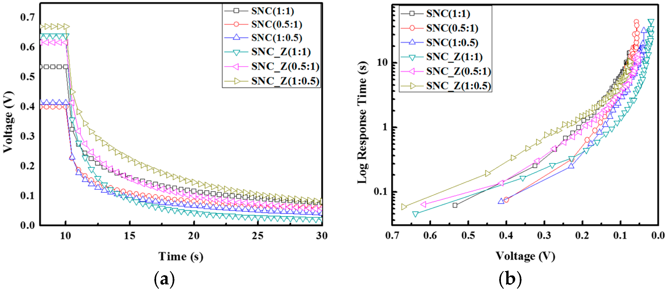
| Sample | Rs (Ω) | Rsh (Ω) | τe (ms) | Deff (cm2·S−1) | Le (cm) |
|---|---|---|---|---|---|
| SNC (1:1) | 12.75 | 151.1 | 10.04 | 1.95 × 10⁻⁵ | 0.447 |
| SNC (1:0.5) | 12.35 | 131.9 | 12.65 | 1.38 × 10⁻⁵ | 0.422 |
| SNC (0.5:1) | 12.72 | 153.6 | 12.65 | 1.56 × 10⁻⁵ | 0.499 |
| SNC_Z (1:1) | 9.02 | 69.33 | 3.99 | 4.90 × 10⁻⁵ | 0.559 |
| SNC_Z (1:0.5) | 9.16 | 69.33 | 6.33 | 3.04 × 10⁻⁵ | 0.555 |
| SNC_Z (0.5:1) | 9.16 | 67.38 | 7.97 | 2.35 × 10⁻⁵ | 0.547 |
© 2016 by the authors; licensee MDPI, Basel, Switzerland. This article is an open access article distributed under the terms and conditions of the Creative Commons Attribution (CC-BY) license (http://creativecommons.org/licenses/by/4.0/).
Share and Cite
Hung, I.-M.; Bhattacharjee, R. Effect of Photoanode Design on the Photoelectrochemical Performance of Dye-Sensitized Solar Cells Based on SnO2 Nanocomposite. Energies 2016, 9, 641. https://doi.org/10.3390/en9080641
Hung I-M, Bhattacharjee R. Effect of Photoanode Design on the Photoelectrochemical Performance of Dye-Sensitized Solar Cells Based on SnO2 Nanocomposite. Energies. 2016; 9(8):641. https://doi.org/10.3390/en9080641
Chicago/Turabian StyleHung, I-Ming, and Ripon Bhattacharjee. 2016. "Effect of Photoanode Design on the Photoelectrochemical Performance of Dye-Sensitized Solar Cells Based on SnO2 Nanocomposite" Energies 9, no. 8: 641. https://doi.org/10.3390/en9080641