1. Introduction
The Organic Rankine Cycle (ORC) provides a means of recovering useful energy from low temperature heat sources. Compared to conventional high temperature steam Rankine cycles, the low temperature of these heat sources means that the attainable cycle efficiency is much lower, while the required surface area of the heat exchangers per unit power output is much higher. Also, the lower latent heat of evaporation of organic fluids relative to steam implies that the feed pump work required in ORCs is a significantly higher proportion of the gross power output. Maximising the net power output from an ORC is a compromise between increasing the mean temperature of heat addition, which is necessary for high cycle efficiency, and increasing the amount of heat extracted from the source, which often requires a lower evaporation temperature. The aim of this study is to investigate the relative performance of difference ORC systems for low temperature heat recovery applications, and the studies described in this paper are based on material presented at the ASME ORC 2015 conference [
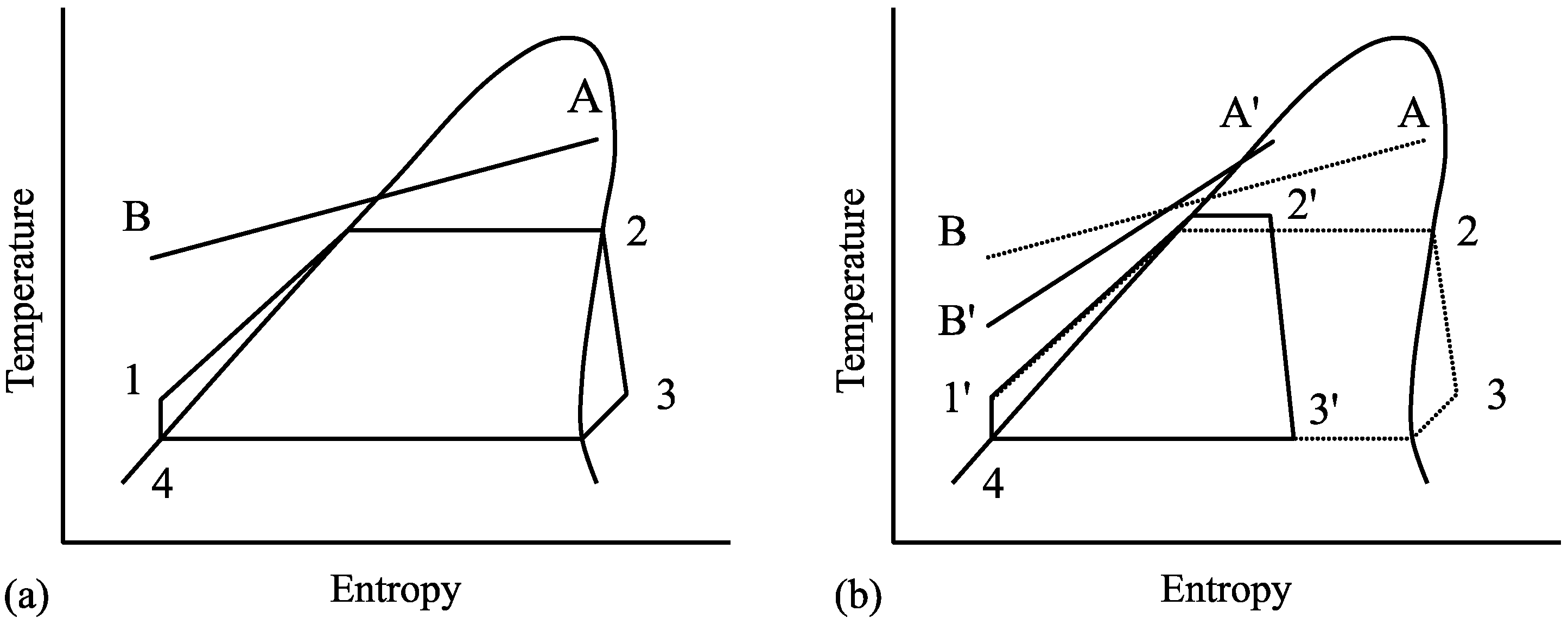
1]. At heat source temperatures of up to 120 °C, a conventional ORC operates with working fluid entering the expander as dry saturated (as shown in
Figure 1a) or superheated vapour. However, in most cases, this leads to the working fluid leaving the expander with some superheat. A heat exchanger is required to cool the fluid to saturation conditions via internal heat exchange (i.e., recuperation) or rejection to the heat sink. Using a screw expander instead of a turbine enables the working fluid to enter the expander as wet vapour. This removes the need to de-superheat the vapour after expansion and raises the evaporation temperature, as shown in
Figure 1b, which can improve the cycle efficiency [
2,
3,
4]. The potential cost and performance benefits of using screw expanders in ORC systems have been extensively studied for geothermal applications by Smith et al. [
5,
6,
7], and the aim of this study is to compare the performance of screw and turbine systems for power generation from low temperature heat sources at both design and off-design conditions. The focus is on the effect of atmospheric air temperature variation on the optimum operating conditions and net power output of the different systems.
Screw expanders are volumetric machines, and their efficiencies are more sensitive to expansion pressure ratio than turbines. At fixed suction and discharge pressures, the expansion ratio increases as the expander inlet vapour dryness fraction decreases. Identifying the conditions that lead to the maximum system power output requires an understanding of how both the screw expander and the feed pump performance vary as the inlet dryness fraction of the working fluid is changed in such a wet vapour ORC (WORC) system. The performance of these systems is considered here for operation at both design and off-design conditions, and compared to equivalent optimised ORC systems using conventional turbine expanders. This also requires an understanding of how the turbine efficiency varies with inlet conditions and the required mass flow rate of the working fluid. The aim of this study is therefore to present a comparative analysis of the design and off-design performance of twin-screw WORC and turbine ORC systems.
As well as the expander performance, pump or fan power is required to drive the coolant through the condenser heat exchanger. The power requirement increases with the coolant flow rate, but a higher coolant flow rate allows the condensing temperature to be reduced for the same minimum temperature difference, leading to a higher cycle efficiency and gross power output. The best combination of these conflicting factors to obtain the condensing temperature that yields the maximum net power output needs also to be estimated. In reality there is some deviation from the idealised Rankine cycles shown in
Figure 1 due to pressure drops in the heat exchangers and the requirement for sub-cooling of the condensed working fluid to avoid cavitation in the feed pump. While these effects do not generally have a large influence on the performance of individual components, the sensitivity of the cycle performance to the operating conditions means that they should also be considered in the analysis of low temperature heat recovery systems.
The size of the heat exchangers required for a particular system depends on the heat transfer rate, the heat transfer coefficients of the fluids and the temperature difference between the fluids. This affects the overall system cost and must therefore be taken into consideration in a full evaluation of the system choice. In practical applications of low temperature heat recovery there is usually a minimum allowable discharge temperature for the source fluid, especially in geothermal power generation, where solid precipitates can form at low temperatures. If required, this lower limit must be included as the cut-off point in evaluating the whole system.
The potential of the WORC as a cost effective system for power recovery from low temperature heat sources was investigated by Leibowitz et al. [
8], but only limited cycle optimisation was performed using a simple expander model with constant efficiency. The performance of ORC systems has therefore been assessed using a more rigorous computational model of the cycle described in
Section 2.
2. Description of Analysis Method and Component Models
A computational ORC model has been developed using a well-established quasi one dimensional model of twin-screw machines. Thermodynamic and fluid properties are obtained from the “Reference Fluid Thermodynamic and Transport Properties Database” program (known as REFPROP) produced by the National Institute of Standards and Technology (NIST). Other cycle components such as the feed pump and motor have been characterised using performance data from manufacturers, and the pressure loss in the heat exchanger components was estimated. Discretised models of the heat source sink and heat exchangers allow the log mean temperature difference (LMTD) to be calculated, and the required surface area for heat transfer can be estimated. Multi-variable optimisation of the cycle operating conditions is implemented using an evolutionary algorithm. This optimisation program has been used to identify the cycle conditions that result in the maximum net power output for a number of specific applications. This paper illustrates how the optimum cycle conditions can be identified for a given temperature and flow rate of the heat source fluid. For the WORC case, the effect of dryness fraction at the expander inlet on the net power output, expander operation and required heat exchanger surface areas is investigated. For the conventional ORC a number of turbine options have been considered including fixed and variable nozzle throat area rotational speed. More details of the cycle and expander models are given below.
2.1. Thermodynamic Cycle Model
The performance of ORC systems has been assessed using a computational model of the cycle. This has been written as an object-oriented program in the C# language. Generic description of heat sources, heat sinks and cycle components have been created containing definitions for all the necessary input and output parameters along with the required calculations. Both simple cycles such as those shown in
Figure 1, and more complex cases (including multiple heat source streams, multiple paths for the working fluid or varying working fluid composition) can be analysed by creating models of the required components and providing the necessary input parameter values. The current study investigates conventional and wet ORC systems as illustrated in
Figure 1. The variables specified as inputs to the cycle model are as follows:
Evaporator inlet pressure;
Condenser outlet pressure;
Enthalpy of fluid at expander inlet (defines fluid quality for screw machine or degree of superheat for turbine);
Temperature drop in subcooler;
Source fluid mass flow rate;
Source fluid inlet and minimum allowable temperatures.
Simplified heat exchanger models have been used with specified pressure loss factors and constant heat transfer coefficients. For the case of design point optimization, the minimum allowable temperature differences in the boiler and condenser heat exchangers have been specified as an input to the model. The “pinch point” temperature differences are varied in the case of off-design calculations in order to maintain constant heat exchanger areas across a range of cycle conditions. The efficiency of the feed pump has been characterised as a function of volumetric flow rate using data from manufacturers.
Once specified, the cycle input parameters allow the required mass flow rate of the working fluid to be calculated. When combined with the expander inlet conditions and discharge pressure, this allows the expander efficiency to be estimated for screw expanders and turbines, as described in the following sections. The net power output and required heat exchanger areas can then be calculated.
2.2. Twin-Screw Expander Model
A thermodynamic model of the expander has been developed to estimate expander efficiency at proposed cycle operating conditions for use in the cycle model. This is based on the quasi one dimensional analysis of twin-screw machines as described by Stosic and Hanjalic [
9], which has been validated for a range of working fluids and operating conditions [
10,
11]. The calculation procedure requires the rotor geometries to be specified in order to calculate machine performance. An initial optimization has therefore been performed to identify suitable rotor profiles for operating conditions representative of the application considered in the current study. The “N” rotor profile developed at City University has been used in the analysis as this geometry is known to have benefits including greater throughput and a stiffer gate rotor than is possible using alternative profiles with similar blow-hole area and sealing line lengths [
2]. For the specified geometry, the characteristics of the screw machine such as the working chamber volume as a function of angular position, sealing line lengths, blowhole area and axial/radial clearances between the rotors and the casing are defined as fixed inputs for the expander model, the main elements of which are described.
In order to find the properties of the working fluid throughout the expansion process and assess machine performance, the fluid flow through the machine is assumed to be quasi one-dimensional. The internal energy of the fluid can be found by applying Equation (1) which describes the conservation of internal energy for non-steady flow in a single working chamber of the machine. The total enthalpy of the fluid at the inflow and outflow of the working chamber are function of the angular position of the main rotor, θ, and are shown in Equations (2) and (3):
The mass flow rates into and out of the working chamber (via the suction and discharge ports and leakage paths) are also functions of the rotor angle, as shown in Equations (4) and (5), and the mass continuity equation is defined in Equation (6):
The subscripts
and
relate to the total mass flow rates of pressure driven leakage flows into and out of the working chamber via the rotor tip, interlobe and end face leakage paths. Characterisation of these leakage flows is achieved by applying the continuity and momentum equations and assuming an isenthalpic throttling process with negligible change in temperature to achieve the expression for leakage mass flow rate given in Equation (7) [
9,
12]:
In Equation (7),
is the leakage flow discharge coefficient (a function of Reynolds and Mach numbers) and
is the leakage flow resistance that can be evaluated as a function of the shape and dimensions of the leakage path and the Reynolds number [
12]. The viscosity of the fluid in the leakage path is therefore required. The leakage fluid is assumed to be at the same conditions as the working chamber from which it is leaking, and the viscosity can be easily obtained for pure liquid or vapour phase conditions. In the case of 2-phase fluid the following assumption has been applied in order to find an approximate value of dynamic viscosity,
, as a function of pressure,
, fluid quality,
, and the saturated liquid and vapour viscosities:
Using these equations, the thermodynamic processes in the expander can be found by considering the working chamber volume as a function of rotor angle (defined by the specified machine geometry and rotor profiles), and combining with the differential equations for internal energy and working chamber mass balance. A fourth order Runge-Kutta numerical method has been used to solve the differential equations. Once the specific internal energy and instantaneous bulk density are known in the working chamber, an equation of state for the working fluid can be used to determine the corresponding temperature, pressure and the quality, if 2-phase. As the mass flow rates into and out of the working chamber depend on the instantaneous chamber mass and internal energy, it is clear that once initial conditions are specified as a function of rotor angle, a number of iterations are required to find a converged solution. Finally, the indicated power output of the expander can be found by calculating the area of the indicated
p-
V diagram. The main parameters used to define the particular screw expander considered in this study are defined in
Table 1.
When considering the performance of a screw expander for a particular application, an important machine parameter is the built-in volume ratio,
, defined as the ratio of working chamber volumes,
, at discharge port opening and suction port closing:
As discharge is always chosen to begin at the maximum working chamber volume, the therefore influences the proportion of the cycle for which the suction port is open. For the suction and discharge pressures specified in the cycle analysis, the mass flow rate and efficiency of the machine will therefore depend on the rotational speed and the . As the mass flow rate is also specified from the cycle model it is clear that iteration is required to identify the appropriate expander operating conditions.
2.3. Turbine Model
Single stage radial inflow reaction turbines are commonly used in ORC applications. These turbines must be sized for specified design point conditions. The flow of working fluid is choked at the throat of the turbine inlet nozzle, and the cross-sectional area at this point must be chosen in order to achieve the required mass flow rate. The operation of the turbine can be characterised by considering the conditions at the throat (denoted by the superscript *) assuming isentropic expansion from turbine inlet conditions (subscript
) as described by Wendt and Mines [
13]. The pressure, density, enthalpy and velocity of the working fluid at the throat can be calculated using the relationships in Equations (10)–(12), where the critical conditions of the working fluid are denoted by the subscript
:
For the mass flow rate required at design conditions (denoted by subscript
), the cross-sectional area at the throat of the nozzle can then be calculated using Equation (13):
The mass flow rate of the working fluid in the cycle will vary at off-design conditions, and two possibilities have therefore been considered for the turbine design:
Fixed nozzle geometry, with constant throat area of ,
Variable nozzle geometry, allowing the value of to be adjusted.
For the fixed geometry case, an upstream throttle valve is required to reduce the turbine inlet pressure to a value which achieves the required mass flow rate through the fixed design throat area. Using variable geometry, the value of
may be varied between zero and a specified maximum value to achieve the required mass flow rate. To characterise the effect of varying inlet and exhaust conditions on turbine performance, the turbine isentropic efficiency can be related to a velocity ratio,
, for the turbine. The velocity ratio is the ratio of the turbine tip speed,
, to the spouting velocity, defined as the velocity achieved if the enthalpy change for an isentropic expansion were entirely converted to kinetic energy, as shown in Equation (14) (where
is the isentropic turbine outlet enthalpy):
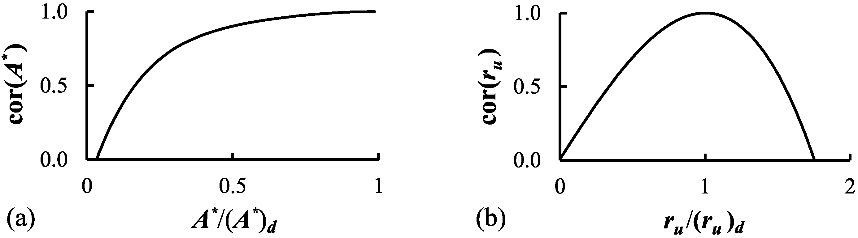
The correlations proposed by Wendt and Mines [
13] are shown in
Figure 2, and have been used to characterise the change in turbine efficiency as a function of both the change in the nozzle throat area resulting from manipulating the nozzle geometry, and the change in the velocity ratio for the expansion process. It is assumed that a turbine can be designed to operate at the required conditions with a specified design efficiency,
. The correction factors,
and
, relating to the throat area and speed ratio respectively, indicate how the turbine efficiency is affected by moving away from the design conditions, as shown in Equation (15):
As the power output of the turbine is in the region of 100 kW, a representative design efficiency of 75% has been assumed for ORCs using both fixed and variable area turbines are considered, where the rotational speed is constant. In order to investigate the potential improvement to the cycle power output by the use of advanced ORC turbine designs, a higher efficiency of 85% has also been considered for the fixed area case [
14,
15]. When the turbine rotational speed is constant, the ratio of velocity ratios,
, becomes the ratio of the design to the actual spouting velocities, leading to variation in the value of
. However, if the tip speed of the turbine is variable then the velocity ratio can be kept equal to the design value. An initial estimate of the performance of an ORC system using a turbine with fixed area and variable speed has therefore also been considered by applying
in all cases, with throttling used where necessary to achieve the required mass flow rate.
The aim of investigating these different possible turbine configurations is to better understand the relative benefits that can be achieved by increasing the complexity of the turbine, generator and/or control system.
2.4. Working Fluid Properties
The REFPROP database developed by NIST has been used to calculate all the thermodynamic properties of the working fluid. The working fluid used in this study for both the saturated vapour and wet ORCs is the refrigerant R245fa, which has a critical temperature of 154 °C. This is sufficiently high to ensure sub-critical pressure in the evaporator. While using fluids with higher critical temperature may increase the achievable net power output by reducing the pressure difference across the feed pump and expander, the reduced vapour density at condenser pressure would significantly increase the size and cost of cycle components. The cost of the R245fa fluid itself is relatively low, and it is widely used in commercial low temperature ORC systems.
2.5. Heat Exchanger Models
A discretized approach has been taken to the calculation of the required surface area in the heat exchangers. Once the temperatures of the source, sink and working fluids have been defined, the heat exchangers are split into a number of short sections and the heat transfer and the log-mean temperature difference (LMTD) are calculated. Representative values for the overall heat transfer coefficient in conventional shell and tube heat exchangers with different fluid phases [
15,
16] are shown in
Table 2, and have been used to calculate the heat transfer surface areas. These are then lumped into two overall heat exchanger areas for “heat addition” (combined feed-heater, evaporator and, if required, super-heater) and “heat rejection” (combined de-superheater, condenser and sub-cooler) which can be sized for design-point conditions. The calculation of heat exchanger areas is essential for the analysis of off-design system operation, and while this simple approach is not expected to be highly accurate for design purposes, it can be used to gain some insight into the requirements of the different cycles.
2.6. Integrated Cycle Model and Optimisation Procedure
There are two important aspects to applying the component models in an integrated cycle model. Firstly, the mass flow rate, identified by consideration of the heat transfer between the source fluid and the working fluid, must be matched to the mass flow rate in the expander itself, which requires iteration of expander operating conditions. Secondly, although the heat transfer surface area of the heat exchangers can be calculated for the design point optimisation, during off-design operation these values must remain fixed. The varying cycle conditions cause changes in the integrated LMTD and the heat transferred in each heat exchanger. Two separate iterative loops are therefore required to identify the pinch point temperature differences required to achieve the necessary area of the boiler/evaporator and the de-superheater/condenser/sub-cooler units to within an allowable error. If, for any reason, the required expander mass flow rate or heat exchanger areas cannot be achieved with particular cycle conditions, the expander efficiency is set to zero. Applying these iterative subroutines allows the cycle to be completely defined, and the net power output can be calculated. Due to the different expander models used for the turbine and screw machine, the details of the calculation procedure are different for the wet and dry vapour ORCs.
2.6.1. Calculation Procedure for WORC with Screw Expander
The required expander suction/discharge pressures, inlet quality and mass flow rate are known from the cycle analysis. As the mass flow rate is an output from the expander model, iteration is required. The matching of the expander to the cycle is discussed in some detail by Read et al. [
17] for both single and multi-stage screw expanders. To find the cycle performance at the design point conditions for the application considered here, the procedure can be summarized as follows:
Specify the suction/discharge pressures and the expander inlet quality and calculate the mass flow rate from cycle model;
Specify the expander built-in volume ratio, BIVR, and iterate using the expander model to find the required speed to match the mass flow rate to within allowable error;
Use the calculated expander efficiency to find the net power output from the cycle model;
Perform a multi-variable optimization to maximize the net power at the design point conditions as a function of suction/discharge pressures, expander inlet quality and BIVR.
The value of the BIVR is limited by the geometry of the rotors, and a practical maximum limit of 4.5 has therefore been applied for the 4/5 lobed rotor configuration considered in this study. For optimisation at off-design conditions, however, a fixed
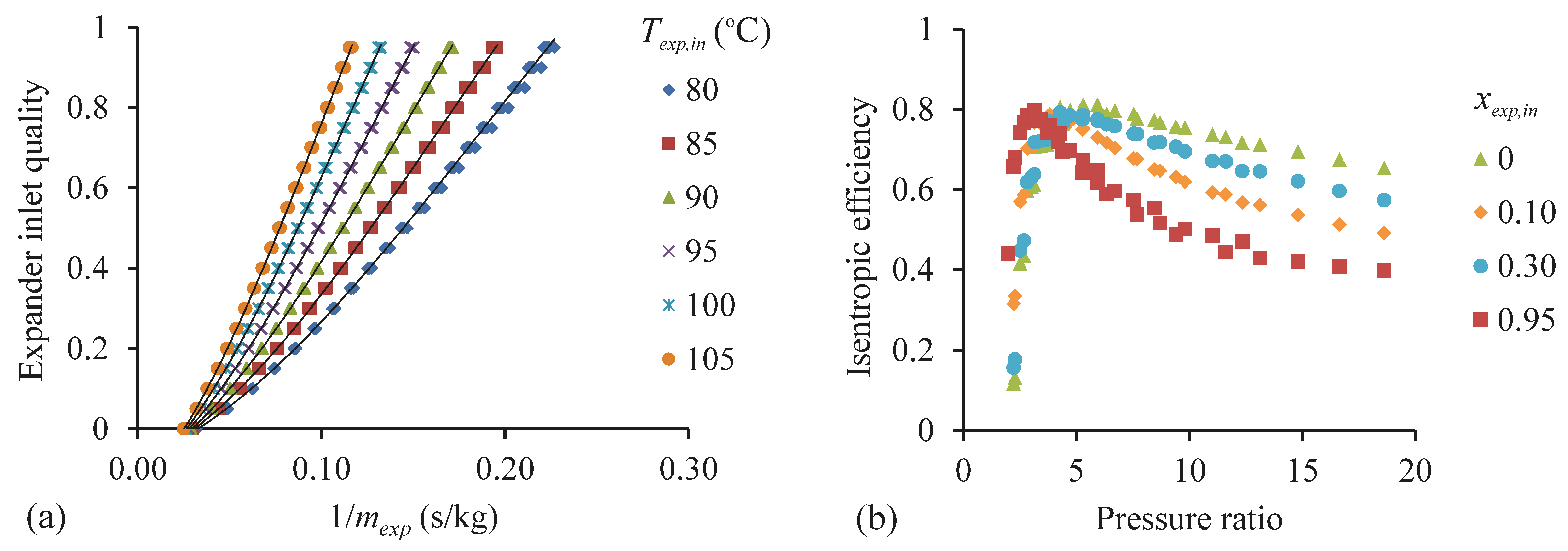
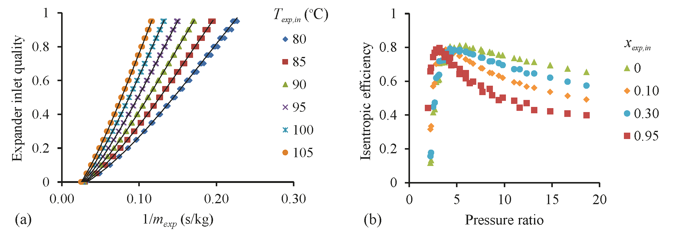
and speed are preferable in order to minimize the expander and generator complexity and control requirements. As the thermodynamic performance calculation for the screw machine is relatively time consuming, it is not practical to perform this calculation for all conditions considered in the cycle optimization, as the error between the cycle and expander mass flow rates must be minimized while also maximizing the net power output. Using the machine parameters identified from the design point optimization, an initial matrix of screw expander performance is therefore calculated as a function of inlet temperature, inlet quality and discharge temperature, over the full range of conditions expected in the application. This allows simple numerical correlations to be derived relating mass flow rate and efficiency to the cycle parameters as illustrated in
Figure 3.
Using correlations such as those shown in
Figure 3, for given cycle conditions the expander mass flow rate and efficiency can be easily estimated, and iteration can be applied to find operating conditions at which the cycle and expander mass flow rates match to within an acceptable error. This allows a rapid initial optimization of cycle operating conditions, which can then be confirmed and refined using the full thermodynamic expander model.
2.6.2. Calculation Procedure for ORC with Turbine
As shown in
Section 2.3, the turbine mass flow rate is calculated as a function of the expander inlet conditions (which may be throttled) and the turbine geometry. For the optimization of the ORC at design conditions, it is assumed that the turbine achieves the specified design isentropic efficiency,
. The required throat area,
, that corresponds to maximum net power output can then be found.
For optimization at off-design conditions, the mass flow rate through the turbine must match that required for the cycle conditions. If the nozzle geometry is fixed, the turbine mass flow rate can only be adjusted by varying the expander inlet conditions, and hence the throat conditions. This is achieved by throttling the flow leaving the boiler prior to the turbine inlet. If the turbine has variable nozzle geometry then it is also possible to adjust the mass flow rate by varying the throat area up to a specified maximum (in this study, the design throat area). An iterative approach is therefore required in order to bring the error between the calculated cycle and turbine mass flow rates below an acceptable value, and identify the required fluid inlet conditions for the expander. For turbines with either fixed or variable nozzle geometry, if the required mass flow rate cannot be achieved by the turbine through throttling and/or nozzle area control then the isentropic efficiency is set to zero in the cycle calculation.
2.6.3. Optimisation Procedure
An evolutionary algorithm has been used to identify the optimum operating conditions for the cycle model. This is a flexible and stable numerical approach which allows for optimisation with any number of variables and is particularly good for distinguishing global from local maxima and coping with discontinuities in the target function. A population of solutions is defined in which each individual solution has a unique “gene” consisting of a “chromosome” for each of the cycle optimisation variables under consideration. The values of the chromosomes are initially randomly generated, and a function is defined in order to calculate the “fitness” of a particular solution. Over successive generations of the calculation procedure, “fitter” genes are used to create new solutions through both combination and random mutation of the chromosomes. Optimisation variables for the cycle analysis are the evaporator and condenser pressures, and the enthalpy at the boiler exit which relates to the expander inlet conditions. For the conventional ORC, this was limited to be greater than or equal to the saturated vapour enthalpy at the specified pressure, in order to avoid liquid at the turbine inlet. For the WORC, the enthalpy was limited to be between the saturated liquid and vapour values, and a further restriction was imposed that the vapour at the exit of the screw should also be less than or equal to the saturated vapour enthalpy at the specified condenser pressure; this was to ensure that sufficient liquid would be present to provide sealing and lubrication of the rotors.
One issue with the evolutionary algorithm method is the lack of a clearly defined convergence criteria. In this study, the optimisation method was implemented as follows:
An initial estimate was made of the optimal system operating conditions;
An initial population of 5000 randomly generated solutions was created, centred on the estimated values (with chromosome values ranging between ±5% for pressures, and ±1% for enthalpy);
The combination and mutation algorithm was implemented for 1000 generations (with two “offspring” from high ranking solution and one randomly generated solution created in each generation), and the best solution identified;
If the best solution had one or more chromosomes outside the original range of values, step (ii) was repeated using the updated estimate;
A check was performed by creating a random population of 1000 centred on the best solution (with the chromosome value ranges reduced by a factor of ten) and if a new best solution was identified the procedure was repeated.
For the design point optimisation, the pinch point temperature differences were fixed at 5 and 10 °C for the boiler and condenser respectively. The calculation of net power output from the cycle model was used as the fitness function. The off-design optimization was performed using the same procedure for a range of air temperatures, but with the fixed values of the expander parameters and heat exchanger areas found for the design conditions.
3. Results
In order to investigate the relative performance of conventional and wet vapour ORCs, and to demonstrate the cycle analysis methods described in
Section 2, a simple case study has been performed for the recovery of heat from a geothermal brine source fluid. This liquid stream has an inlet temperature of 120 °C and contains a recoverable heat content of 2.7 MW if cooled to an ambient temperature of 10 °C; however, a minimum allowable brine temperature of 70 °C has been imposed as this represents a typical limit for controlling the formation of precipitates. The study presented below has investigated the generation of power from this heat source using both conventional and wet ORCs with the following characteristics:
The working fluid is refrigerant R245fa;
An air cooled condenser is used with 2 °C sub-cooling of the working fluid at the exit;
Minimum pinch point temperature differences of 5 and 10 °C respectively have been applied for the boiler and condenser for the design-point optimization;
The efficiency of the feed pump has been characterised as a function of volumetric flow and pressure difference rate using data from manufacturers;
An efficiency of 95% has been assumed for the electrical generator and 90% for the pump/fan motors;
Mechanical efficiencies of 90% and 94% have been used for screw and turbine expanders respectively;
A pressure drop of 5% has been assumed across the feed heater and condenser heat exchangers.
The results for the design point and off-design optimization of the ORC system model, described in
Section 2, are shown below. For this type of application, if the fluid leaving the expander is superheated, as is likely for a conventional ORC, the cycle efficiency, and hence the power output, can be improved via recuperation. This is due to the minimum allowable source temperature being well above the feed pump exit temperature when operating at design conditions, although close temperature matching between the superheated vapour and the sub-cooled liquid often necessitates a relatively large heat exchanger. In order to simplify the system analysis and the matching of the heat exchanger areas at off-design conditions, this study assumes that no recuperation is used to recover heat from the superheated turbine exit vapour.
3.1. Design Point Optimisation
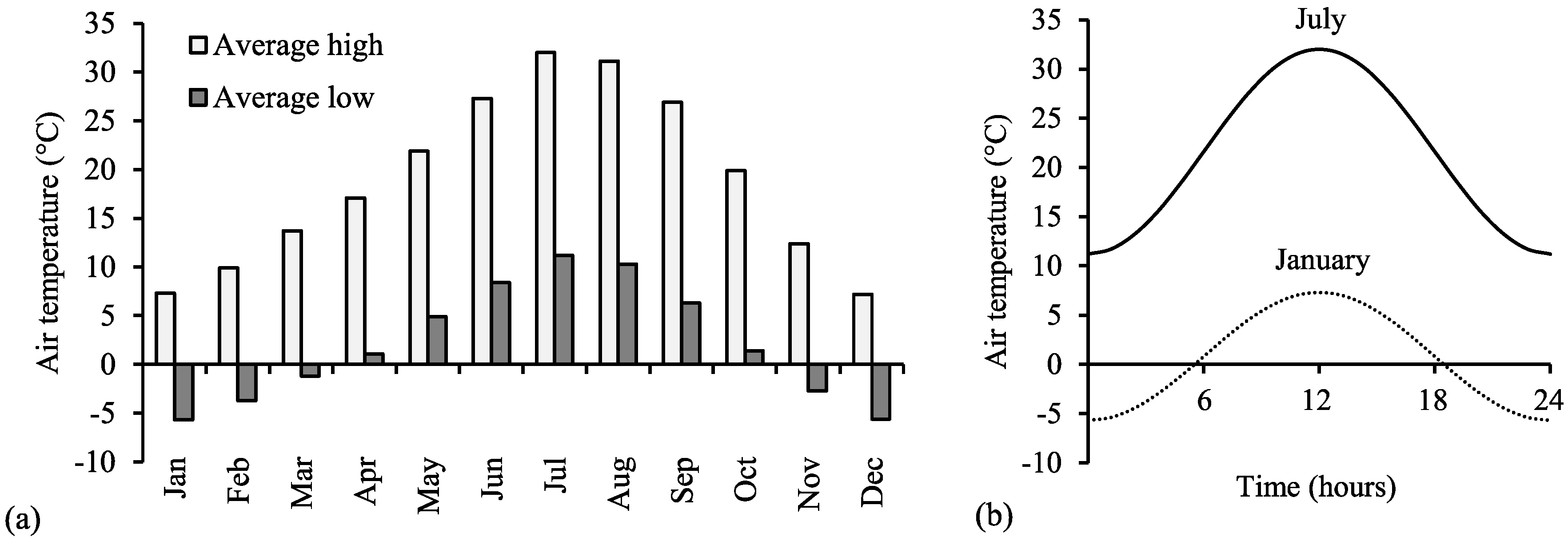
Operation of the ORC systems has been considered for average climate conditions in Nevada, USA where there are significant geothermal resources of this type. The annual mean temperature is 10.5 °C, with monthly variations in the average maximum and minimum temperatures shown in
Figure 4. A design-point optimisation has been performed for this annual mean temperature. The fixed parameters for this optimisation are shown in
Table 3, and the results for the ORC systems using twin-screw and turbine expanders are shown in
Table 4 and
Table 5 respectively.
The results for the conventional ORC systems shown in
Table 5 indicate that the performance can potentially be improved by using a recuperator to pre-heat the fluid exiting the feed pump while cooling the superheated vapour at the turbine exit. The enthalpy available from the superheated vapour is however only around 5% of the total enthalpy change of the working fluid during heat addition, and recuperation therefore does not greatly affect the cycle performance. The effect of recuperation on design and off-design ORC system performance will be considered in future work.
In order to assess the effect that the off-design performance has on the operation of the ORC systems throughout the year, it has been assumed that for a typical day, the temperature has a sinusoidal variation between the average monthly maximum and minimum temperatures as shown in
Figure 4. The variation in power with temperature through the course of a typical day in each month can then be calculated, and the mean power output for each month can be found. The off-design performance of the optimised ORCs has been investigated by identifying the conditions required to achieve maximum net power output from the systems defined in
Table 4 and
Table 5 for a range of air temperatures from −10 to 40 °C.
3.2. Optimum Parameters for a Conventional ORC as a Function of Air Temperature
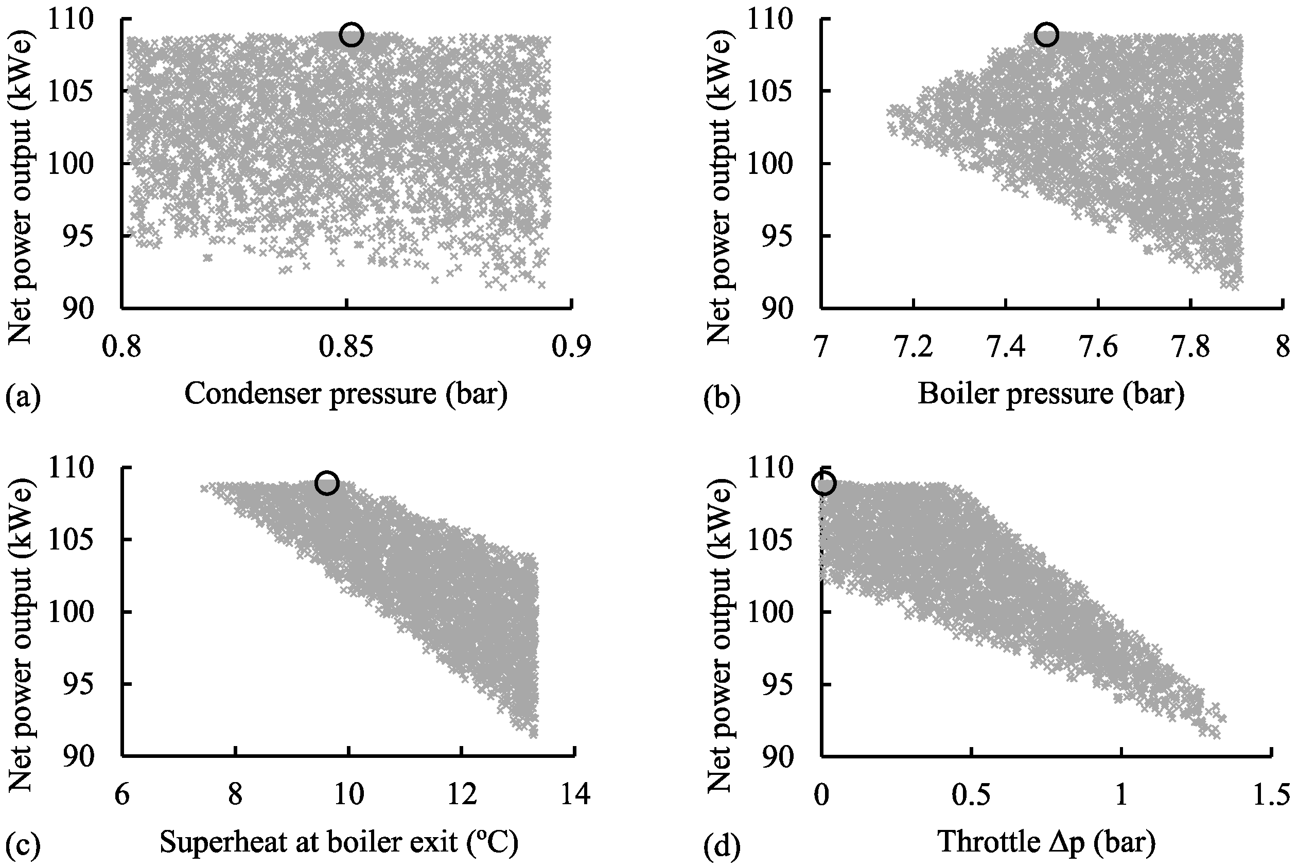
An example of the data produced in the off-design optimization procedure is given in
Figure 5. This shows how the choice of operating conditions can have a significant effect on the net power output, with small variations in conditions (±5% for pressures) reducing power output by up to 20%. It is also clear however that the ‘peak’ of the curve is relatively broad, with a range of conditions achieving very close to the maximum power output. An interesting result from the off-design optimization is the fact that in all cases, the maximum net power output was found to occur with negligible throttling prior to the expander entry, as illustrated in
Figure 5. It is however important to include the throttling process in the cycle model as it allows the optimization procedure to create a wide range of solutions and close in on the optimum (unthrottled) case.
In all cases, the off-design analysis achieved an error of less than 0.1% between the design-point and off-design values of the heat transfer surface area for the boiler and condenser heat exchangers. Reducing this allowable error was found to have negligible effect on the net power output from the system; with an air temperature of 30 °C for example, a maximum error of in the heat exchanger areas was found to change the calculated net power output by less than 0.05%.
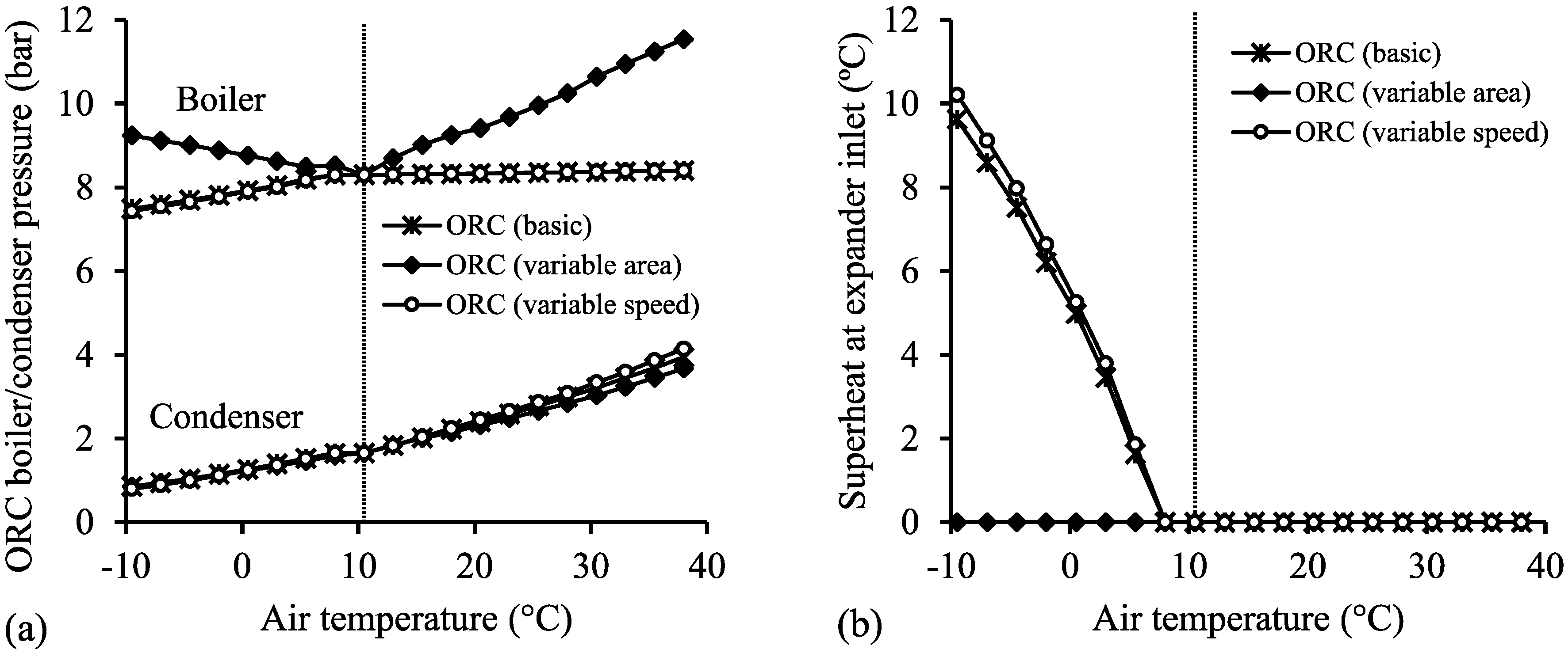
Overall results for the optimisation of the conventional ORC using basic turbine (fixed speed and nozzle area, 75% isentropic efficiency at design conditions), variable speed and variable area turbines are shown in
Figure 6 and
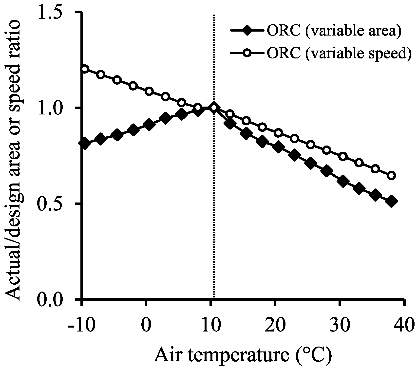
Figure 7. At all air temperatures, the operating conditions of the ORC with basic and variable speed turbines are very similar. The greater operating flexibility of the variable area turbine allows higher boiler pressure, which is a compromise between reducing heat recovery from the source and raising cycle efficiency due to the higher mean temperature of heat addition. The operating conditions required for the variable area and speed turbines are shown in
Figure 7; the area is seen to varying between 50% and 100% of the design condition, while the speed varies between 65% and 120% of the design value.
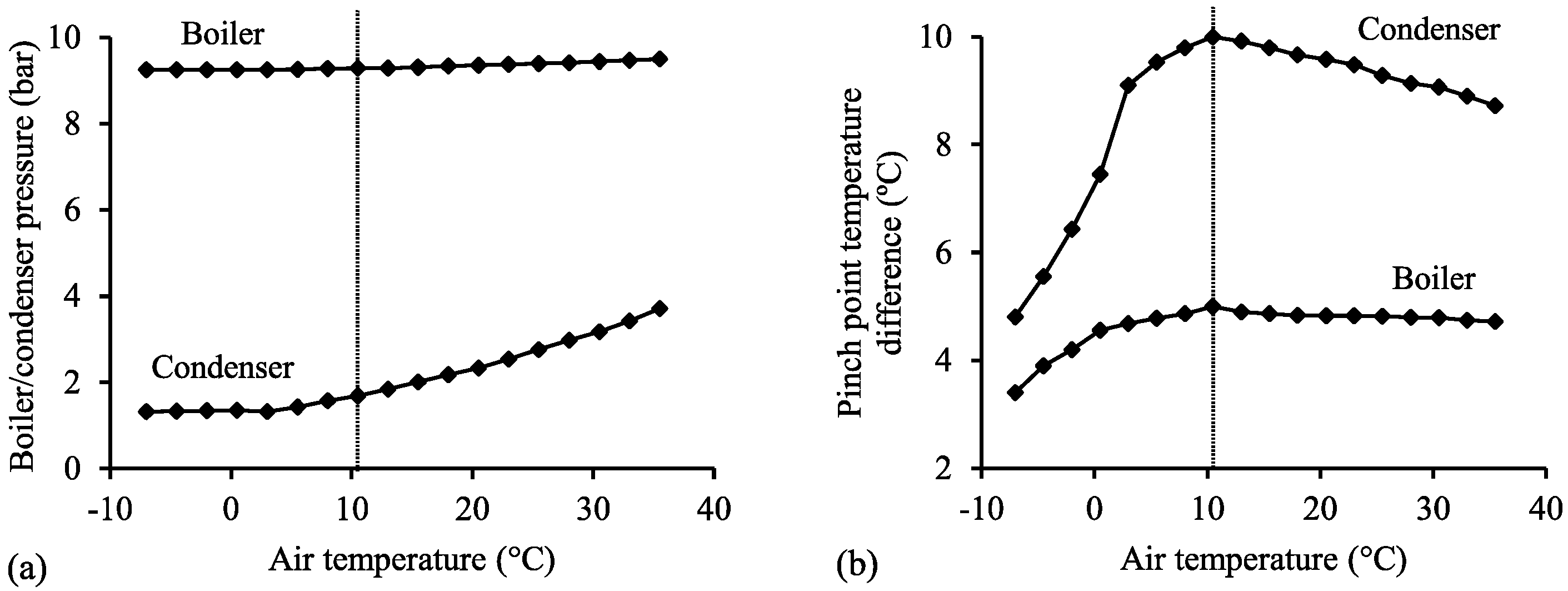
3.3. Optimum Parameters for WORC as Function of Air Temperature
A key aim of the study was to investigate how the performance of the WORC using a positive displacement expander should be optimized in order to maximise net power output of the system, within the constraints of fixed rotor speed and built-in volume ratio,
(defined in Equation (9)). The resulting variation in optimum boiler/condenser pressure, pinch points, expander inlet dryness fraction and expansion volume ratio are shown in
Figure 8 and
Figure 9.
3.4. Overall Off-Design Performance of Wet and Conventional ORC Systems
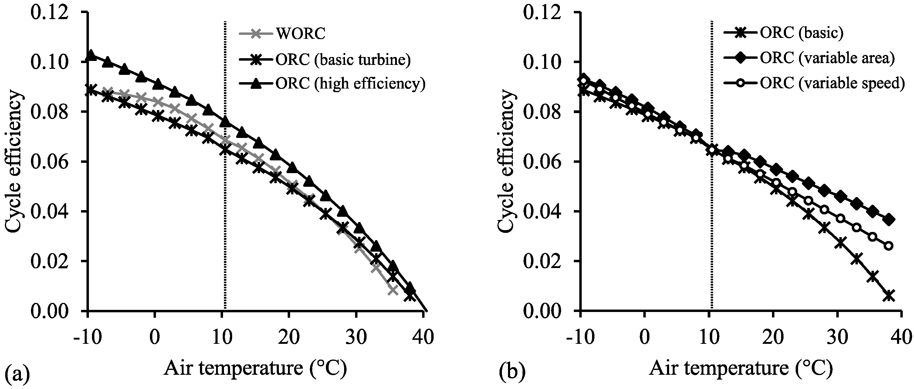
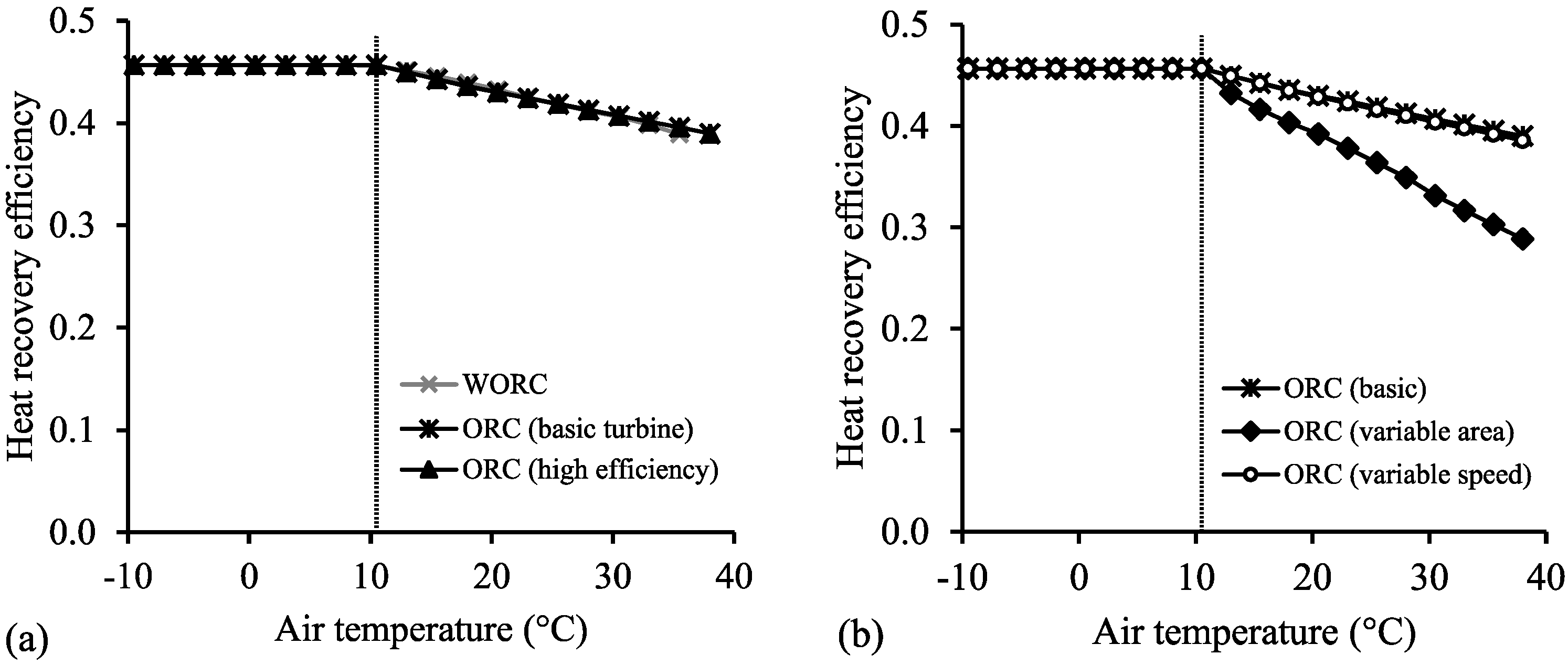
The heat recovery efficiency refers to the fraction of available heat from the source fluid that is transferred into the cycle, and the cycle efficiency is the net power output divided by the heat input. These efficiencies are defined in Equations (16) and (17) respectively:
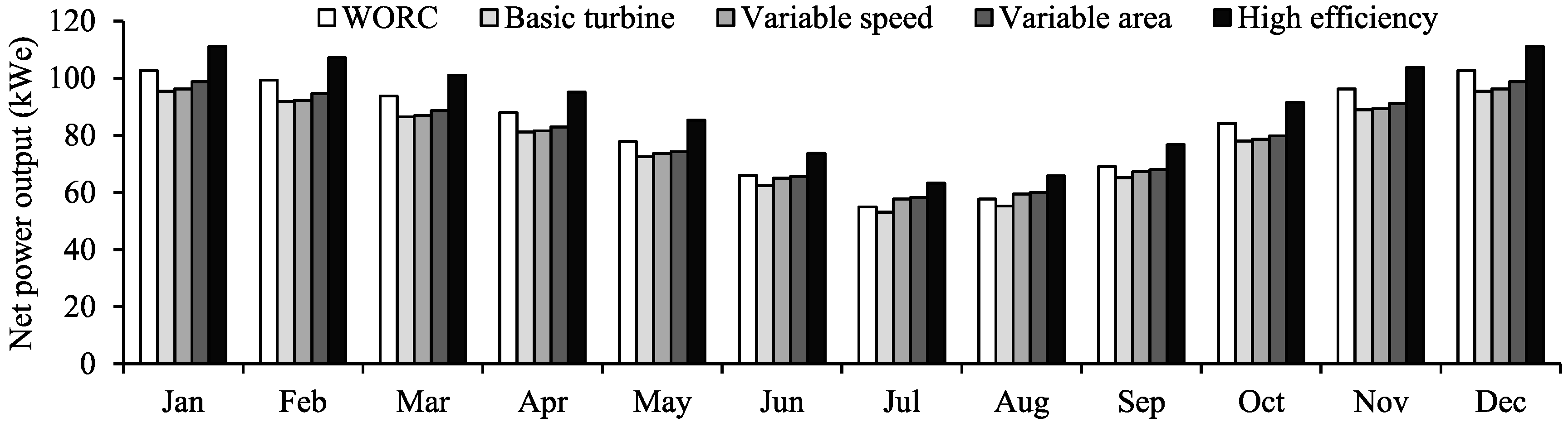
Based on the results shown in
Figure 10 and temperature profile shown in
Figure 4, the estimated time-averaged power output from the ORC systems for each month are given in
Figure 14. The values of net power output calculated for both design-point and time-averaged annual conditions are compared in
Table 6, which also shows a comparison between the calculated overall heat transfer areas for heat addition and heat rejection in the different ORC systems.
4. Discussion
The results in
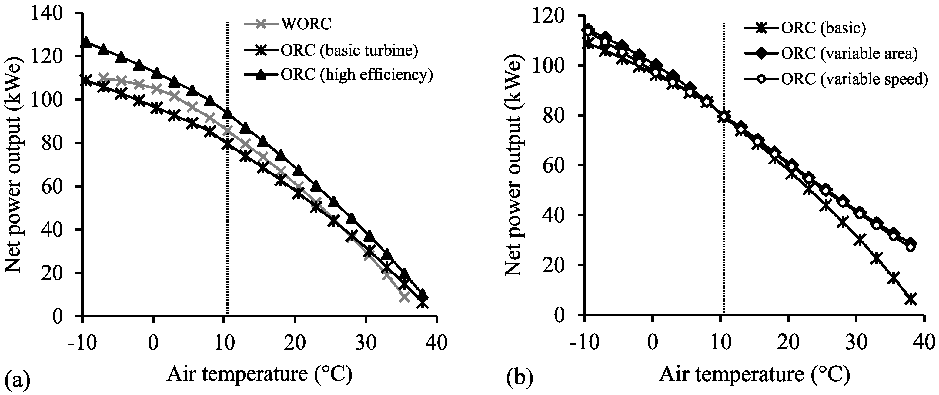
Figure 10 show that variation in air temperature has a large effect on the maximum net power output possible from the different ORC systems. The main effect of increasing air temperature on the cycle conditions is the increase in condenser pressure. In all cases, off-design operation can be optimised by allowing variation in the inlet pressure and pinch point conditions in the boiler and condenser. For the systems considered, positive net power output was achieved for air temperatures up to at least 35 °C. The power output is greatest during the winter months, where there is little daily variation between maximum and minimum values. During the summer months, power generation in the hottest part of the day can fall as low as 25% of the daily maximum. The time-averaged net power output is seen to be reasonably similar for all systems, at around 80 kWe, and is close to the results for the design point calculation using the average air temperature. For this type of application with a constant heat source temperature and flow rate, the use of the average annual temperature to perform the design point calculations is seen to provide a good initial estimate of the real-world system performance.
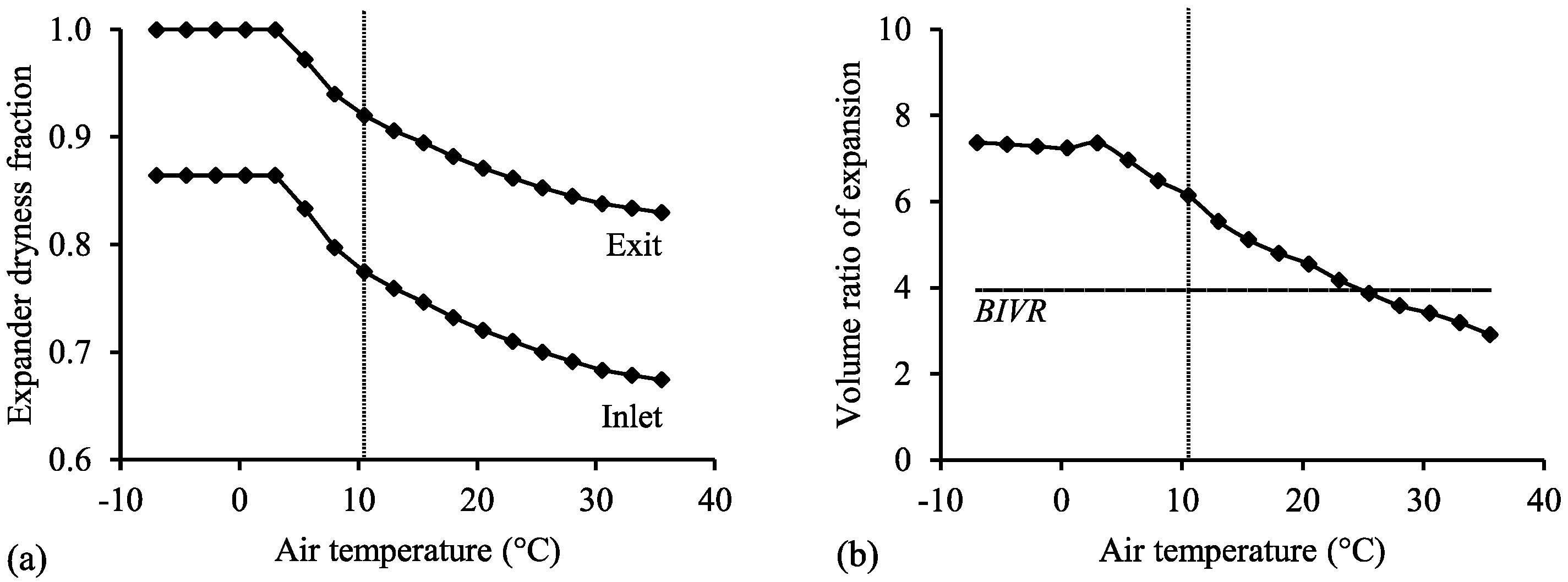
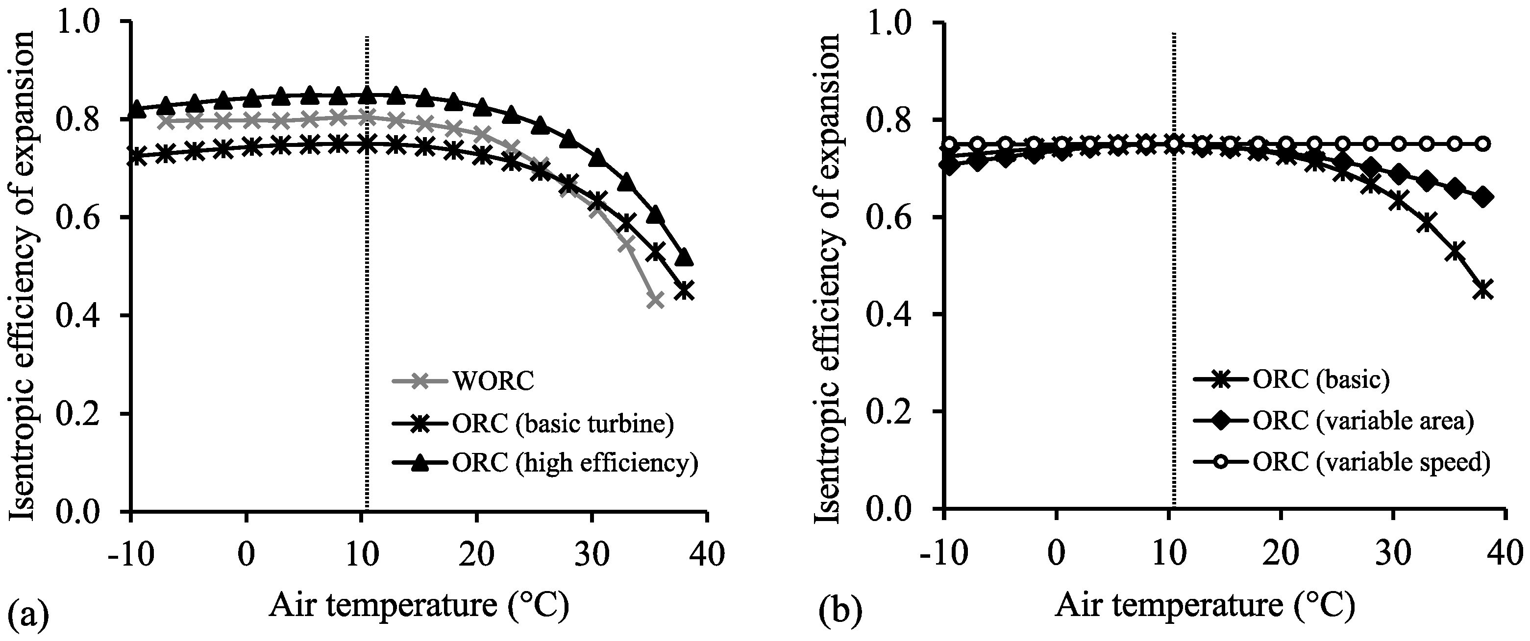
For the screw expander in a WORC, the dryness fraction at the inlet to the expander can also be varied, while the BIVR and rotor speed of the expander are kept constant. This decreases the overall volume ratio for the expansion process. The BIVR of the screw expander is however fixed in this study, which at higher temperatures (over 25 °C) leads to over-expansion of the working fluid and a decrease in expander efficiency (as shown in
Figure 9 and
Figure 10), reducing the net power output. As air temperature decreases the optimum expander inlet dryness fraction tends to increase. The WORC optimisation has been performed with the constraint of wet or dry-saturated vapour at the expander outlet in order to ensure adequate sealing and lubrication. Maximum net power output is achieved at this limiting case of dry-saturated expander exit vapour when the air temperature falls below 5 °C. The boiler and condenser pressures are then approximately constant, and the required values of heat exchanger area are then achieved by decreasing the pinch point temperature differences. Other than at the higher temperatures, where efficiency falls due to over-expansion in the screw, the WORC generally achieves a power output around midway between the conventional ORCs with turbine efficiencies of 75% and 85%, which is reflected in the time-averaged results presented in
Table 6. The reduction of efficiency due to over-expansion of the working fluid at high air temperatures in largely caused by the fixed built-in volume ratio of the machine. It may therefore be possible to improve the high temperature performance of the WORC system by allowing optimisation of the expander speed and/or built-in volume ratio in order to better match the volume ratio of the expansion process. The increase in net power output is however expected to be small due to the limited periods of time spent operating at these higher air temperatures.
In the conventional ORCs, optimum operating conditions are seen to depend on the turbine control. For the basic and variable speed turbines optimum conditions are very similar. Boiler and condenser pressures are constant at air temperatures above the design point, with zero superheat. At lower temperatures, the boiler and condenser pressures both fall and the required superheat rises to a maximum of around 10 °C at an air temperature of −10 °C. The variable speed turbines maintain an efficiency of 75% at all air temperatures, resulting in higher cycle efficiency and net power output, most significantly at high air temperature, where the basic turbine efficiency falls due to significant mismatch between actual and design velocity ratios. However, from
Figure 4 it is clear that operation at these high temperatures is relatively rare, and the benefits in the time averaged power output are therefore small (an increase of 1.9% for the annual average), as shown in
Figure 14 and
Table 6.
For the variable area turbine, optimum conditions are found to occur with higher boiler pressure at temperatures both higher and lower than the design point, which is achieved by reducing the nozzle area. At higher temperatures, this raises the exit temperature of the source fluid, limiting the heat recovery efficiency. This is however offset by the higher cycle efficiency; a result of the increased mean temperature of heat addition. The resulting net power output for the variable area case is slightly higher than for the variable speed case across the range of air temperatures, but again, only increases the annual time-average net power output by a relatively small 3.8%. These results suggest that for this type of application, the small increase in power output available from the variable speed and geometry turbines are much less significant than those resulting from improved turbine efficiency, and are unlikely to be sufficient to justify the additional complexity and cost of such systems.
The results of this study suggest that the required heat exchanger areas are similar for the different systems. The WORC has a slightly larger heat transfer area for the boiler due to the closer temperature matching between the source and working fluids, while the conventional ORCs have slightly larger air-cooled condenser heat transfer areas. The condenser area is more important as it is likely to represent a significant proportion of the total system cost due to its large size. However, more detailed consideration of the design and performance of heat exchangers and the associated heat transfer coefficients would be required to investigate how the choice of system influences the equipment costs. The possible economic benefits of using twin-screw machines in WORC systems has already been discussed in detail [
7,
8], and the results here suggest that performance can match or exceed conventional ORCs for relatively low power applications. It is however worth noting that the isentropic efficiency of current turbines increases with power up to a maximum of around 83% for large-scale geothermal applications [
13]. While the efficiency of twin-screw machines also generally improves with size and power output (due to the relative reduction in leakage flows), standard screw machine rotors are currently produced with a practical manufacturing limit of around half a meter. Using the model presented in this paper, the performance of a 512 mm diameter screw expander at the optimum operating conditions identified for the WORC, and operating with the same tip speed of 48m/s, is predicted to achieve expander isentropic efficiencies of around 84% and a net power output of around 590 kWe.
5. Conclusions
In this paper, the optimisation and off-design operation of low temperature heat recovery systems has been demonstrated. The case study considered above suggests that similar overall performance can be achieved by ORC systems using both twin-screw and turbine expanders. The results indicate that for the application considered (where the heat source conditions remain constant) there is little benefit, in terms of average power output, in using turbines with variable geometry or speed. While the efficiency of the screw expander is seen to decrease more rapidly than the turbine at higher air temperatures, the WORC is predicted to achieve comparable design-point and time-averaged performance. The choice of system for a particular application is therefore likely to be strongly influenced by other factors such as initial and operational costs, component design limitations, reliability, system control and off-design performance. The model described can be used for a wide range of applications, and allows comparative studies of the performance of low temperature heat recovery systems and their components. Future work will focus on investigating the possible benefits of regenerative feed heating and optimum working fluid selection in both ORC systems, while more detailed heat exchanger and pump models are being developed to improve the understanding of off-design performance and the necessary control systems required to maximize power output.
Acknowledgments
This study was internally funded by the Centre for Compressor Technology at City University London.
Author Contributions
Matthew Read, Ian Smith and Nikola Stosic conceived the study; Matthew Read developed the analysis tools, performed the analysis and wrote the paper; Ian Smith, Nikola Stosic and Ahmed Kovacevic contributed to analysis tools.
Conflicts of Interest
The authors declare no conflict of interest.
Abbreviations
| Built-In Volume Ratio |
| Boiler |
| Condenser |
| Discharge |
| Expander |
| Log Mean Temperature Difference |
| ORC | Organic Rankine Cycle |
| Superheat |
| Suction |
| Turbine |
| WORC | Wet Organic Rankine Cycle |
References
- Read, M.G.; Kovacevic, A.; Smith, I.K.; Stosic, N. Comparison of Organic Rankine Cycle Systems under Varying Conditions Using Turbine and Twin-Screw Expanders. In Proceedings of the 3rd International Seminar on ORC Power Systems, Brussels, Belgium, 12–14 October 2015.
- Smith, I.K.; Stosic, N.; Kovacevic, A. Power Recovery from Low Grade Heat by Means of Screw Expanders, 1st ed.; Elsevier: Amsterdam, The Netherlands, 2014. [Google Scholar]
- Read, M.G.; Smith, I.K.; Stosic, N. Multi-Variable Optimisation of Wet Vapour Organic Rankine Cycles with Twin-Screw Expanders. In Proceedings of the 22nd International Compressor Engineering Conference, Purdue, IN, USA, 14–17 July 2014; p. 2359.
- Read, M.G.; Smith, I.K.; Stosic, N. Effect of Air Temperature Variation on the Performance of Wet Vapour Organic Rankine Cycle Systems; Transactions of Geothermal Resource Council: Davis, CA, USA, 2014; pp. 705–712. [Google Scholar]
- Smith, I.K.; Stosic, N.; Kovacevic, A. Power Recovery from Low Cost Two-Phase Expanders; Transactions of Geothermal Resource Council: Davis, CA, USA, 2001; pp. 601–605. [Google Scholar]
- Smith, I.K.; Stosic, N.; Kovacevic, A. An improved System for Power Recovery from Higher Enthalpy Liquid Dominated Fields; Transactions of Geothermal Resource Council: Davis, CA, USA, 2004; pp. 561–565. [Google Scholar]
- Smith, I.K.; Stosic, N.; Kovacevic, A. Screw Expanders Increase Output and Decrease the Cost of Geothermal Binary Power Plant Systems; Transactions of Geothermal Resource Council: Davis, CA, USA, 2005; pp. 787–794. [Google Scholar]
- Leibowitz, H.; Smith, I.K.; Stosic, N. Cost effective small scale ORC systems for power recovery from low grade heat sources. In Proceedings of the ASME 2006 International Mechanical Engineering Congress and Exposition, Chicago, IL, USA, 5–10 November 2006; pp. 521–527.
- Stosic, N.; Hanjalic, K. Development and optimization of screw machines with a simulation model—Part I: Profile generation. J. Fluids Eng. 1997, 119, 659–663. [Google Scholar] [CrossRef]
- Smith, I.K.; Stosic, N.; Aldis, C.A. Development of the trilateral flash cycle system: Part 3: The design of high-efficiency two-phase screw expanders. Proc. Inst. Mech. Eng. Part A J. Power Energy 1996, 210, 75–93. [Google Scholar] [CrossRef]
- Read, M.G.; Smith, I.K.; Stosic, N. Optimization of screw expanders for power recovery from low-grade heat sources. J. Energy Technol. Policy 2014, 1, 131–142. [Google Scholar] [CrossRef]
- Sakun, I.A. Screw Compressors; Mashgiz Press: Moscow, Russia, 1960. (In Russian) [Google Scholar]
- Wendt, D.S.; Mines, G.L. Simulation of Air-Cooled Organic Rankine Cycle Geothermal Power Plant Performance; Report No. INL/EXT-13–30173; U.S. Department of Energy Idaho National Laboratory: Idaho Falls, ID, USA, 2013.
- Kang, S.H. Design and experimental study of ORC (organic Rankine cycle) and radial turbine using R245fa working fluid. Energy 2012, 41, 514–524. [Google Scholar] [CrossRef]
- Uusitalo, A. Working Fluid Selection and Design of Small-Scale Waste Heat Recovery Systems Based on Organic Rankine Cycles. Ph.D. Thesis, Acta Universitatis Lappeenrantaensis, Lappeenranta University of Technology, Lappeenranta, Finland, 2014. [Google Scholar]
- Roetzel, W.; Spang, B. VDI Heat Atlas: C3 Typical Values of Overall Heat Transfer Coefficients; Springer: Berlin, Germany, 2010; pp. 75–78. [Google Scholar]
- Read, M.G.; Smith, I.K.; Stosic, N. Optimisation of Two-Stage Screw Expanders for Waste Heat Recovery Applications; IOP Conference Series: Materials Science and Engineering: London, UK, 2015; Volume 90. [Google Scholar]
Figure 1.
Illustrative T-s diagrams showing: (a) Conventional ORC with dry saturated vapour at the expander inlet; (b) How the expansion of wet vapour can avoid superheated vapour and increase heat recovery. Points A and B are the source fluid inlet and exit conditions, while feed pump and turbine inlet/exit conditions are shown by point 4/1 and 2/3 respectively. Dashes represent the modified conditions in the wet vapour ORC.
Figure 2.
Efficiency correction factors as functions of: (a) Throat area; (b) Velocity ratio relative to the design values.
Figure 2.
Efficiency correction factors as functions of: (a) Throat area; (b) Velocity ratio relative to the design values.
Figure 3.
Illustration of screw expander performance data generated for a given design point machine geometry and speed (BIVR = 3.2, 4500 rpm), showing correlations for; (a) Mass flow rate; (b) Isentropic efficiency as functions of expander inlet temperature and quality, and pressure ratio. For each inlet temperature, results are shown for discharge temperatures ranging from 0 to 50 °C.
Figure 4.
(a) Monthly average maximum and minimum air temperatures in Nevada USA; (b) Examples of assumed daily sinusoidal variation of air temperature.
Figure 4.
(a) Monthly average maximum and minimum air temperatures in Nevada USA; (b) Examples of assumed daily sinusoidal variation of air temperature.
Figure 5.
Example of results from optimization procedure, showing; (a) Boiler pressure; (b) Condenser pressure; (c) Superheat at boiler exit; (d) Pressure drop across throttle in order maximize net power at off-design conditions in a conventional ORC with air temperature −10 °C and (circle shows optimum operating point).
Figure 6.
Results showing optimization of: (a) Boiler/condenser pressures; (b) Superheat at boiler exit in order maximize net power at off-design conditions, and required turbine control conditions for variable area and variable speed operation.
Figure 6.
Results showing optimization of: (a) Boiler/condenser pressures; (b) Superheat at boiler exit in order maximize net power at off-design conditions, and required turbine control conditions for variable area and variable speed operation.
Figure 7.
Results showing required turbine control conditions for variable area and variable speed operation at optimum conditions.
Figure 7.
Results showing required turbine control conditions for variable area and variable speed operation at optimum conditions.
Figure 8.
(a) Boiler and condenser pressure; (b) Pinch point temperature differences required for maximum net power output at off-design conditions using WORC optimised for 10.5 °C air temperature.
Figure 8.
(a) Boiler and condenser pressure; (b) Pinch point temperature differences required for maximum net power output at off-design conditions using WORC optimised for 10.5 °C air temperature.
Figure 9.
Results for screw expander: (a) Inlet and exit dryness fractions; (b) Volume ratio of expansion process (with expander shown as dashed line) required for maximum net power output at off-design conditions using WORC optimised for 10.5 °C air temperature.
Figure 9.
Results for screw expander: (a) Inlet and exit dryness fractions; (b) Volume ratio of expansion process (with expander shown as dashed line) required for maximum net power output at off-design conditions using WORC optimised for 10.5 °C air temperature.
Figure 10.
Maximum net power output as a function of air temperature for: (a) WORC using screw expander and ORC using basic and high efficiency turbines; (b) ORC using basic, variable speed and variable area turbines.
Figure 10.
Maximum net power output as a function of air temperature for: (a) WORC using screw expander and ORC using basic and high efficiency turbines; (b) ORC using basic, variable speed and variable area turbines.
Figure 11.
Isentropic efficiency of expansion process: (a) WORC using screw expander and ORC using basic and high efficiency turbines; (b) ORC using basic, variable speed and variable area turbines.
Figure 11.
Isentropic efficiency of expansion process: (a) WORC using screw expander and ORC using basic and high efficiency turbines; (b) ORC using basic, variable speed and variable area turbines.
Figure 12.
Cycle efficiency as functions of air temperature for: (a) WORC using screw expander and ORC using basic and high efficiency turbines; (b) ORC using basic, variable speed and variable area turbines.
Figure 12.
Cycle efficiency as functions of air temperature for: (a) WORC using screw expander and ORC using basic and high efficiency turbines; (b) ORC using basic, variable speed and variable area turbines.
Figure 13.
Heat recovery efficiency as functions of air temperature for: (a) WORC using screw expander and ORC using basic and high efficiency turbines; (b) ORC using basic, variable speed and variable area turbines.
Figure 13.
Heat recovery efficiency as functions of air temperature for: (a) WORC using screw expander and ORC using basic and high efficiency turbines; (b) ORC using basic, variable speed and variable area turbines.
Figure 14.
Comparison of monthly time-averaged net power output for the WORC, and ORC using basic, variable speed, variable area and high efficiency turbines.
Figure 14.
Comparison of monthly time-averaged net power output for the WORC, and ORC using basic, variable speed, variable area and high efficiency turbines.
Table 1.
Parameters used for analysis of twin-screw expander.
Table 1.
Parameters used for analysis of twin-screw expander.
| Parameter | Value |
|---|
| Working fluid | R245fa |
| Lobe No. of main/gate rotor | 4/5 |
| Maximum BIVR | 4.5 |
| Main rotor speed | 4500 rpm |
| Main rotor diameter | 204 mm |
| Rotor length | 316 mm |
| Wrap angle | 300° |
| Axial clearances | 100 μm |
| Radial clearances | 100 μm |
| Interlobe clearance | 100 μm |
| Mechanical efficiency | 90% |
Table 2.
Representative values of overall heat transfer coefficient for ORC shell and tube heat exchangers with different states for the heat transfer fluids.
Table 2.
Representative values of overall heat transfer coefficient for ORC shell and tube heat exchangers with different states for the heat transfer fluids.
| State of the Heat Transfer Fluids | Approximate Overall Heat Transfer Coefficient (W/m2·K) |
|---|
| Liquid or 2-phase/Liquid | 1200 |
| Liquid or 2-phase/Vapour | 70 |
| Vapour/Vapour | 35 |
Table 3.
Fixed parameters for design point optimisation of ORC systems.
Table 3.
Fixed parameters for design point optimisation of ORC systems.
| Parameter | Value |
|---|
| Working fluid | R245fa |
| Boiler design pinch point | 5 °C |
| Condenser design pinch point | 10 °C |
| Air temperature at design point | 10.5 °C |
| Source fluid inlet temperature | 120 °C |
| Minimum allowable source temperature | 70 °C |
Table 4.
Optimised parameters for WORC with twin-screw expander operating at the design point conditions stated in
Table 3.
Table 4.
Optimised parameters for WORC with twin-screw expander operating at the design point conditions stated in Table 3.
| Parameter | Units | Value |
|---|
| bar | 9.28 |
| bar | 1.68 |
| % | 80.4 |
| Dryness fraction, | - | 0.75 |
| Dryness fraction, | - | 0.91 |
| - | 3.94 |
| Mass flow rate, | kg/s | 6.44 |
| °C | 70.0 |
| (electrical) | kWe | 109.4 |
| (electrical) | kWe | 17.8 |
| (electrical) | kWe | 6.0 |
| (electrical) | kWe | 85.6 |
Table 5.
Optimised parameters for a non-recuperated ORC with “basic” and “advanced” turbine expanders operating at the design point conditions stated in
Table 3.
Table 5.
Optimised parameters for a non-recuperated ORC with “basic” and “advanced” turbine expanders operating at the design point conditions stated in Table 3.
| Parameter | Units | Value |
|---|
| Turbine design efficiency | % | 75 | 85 |
| bar | 8.30 | 8.32 |
| bar | 1.65 | 1.63 |
| at turbine inlet | °C | 0 | 0 |
| at turbine exit | °C | 16.1 | 13.7 |
| kg/s | 5.37 | 5.36 |
| °C | 70 | 70 |
| (electrical) | kWe | 102.8 | 117.6 |
| (electrical) | kWe | 18.7 | 19.4 |
| (electrical) | kWe | 4.6 | 4.6 |
| (electrical) | kWe | 79.5 | 93.6 |
Table 6.
Comparison of net power output and heat exchanger areas for the different ORC systems.
Table 6.
Comparison of net power output and heat exchanger areas for the different ORC systems.
| Cycle | WORC | Basic | Variable Speed | Variable Area | High η |
|---|
| Design-point (kWe) | 85.6 | 79.5 | 79.5 | 79.5 | 93.6 |
| Time-averaged annual (kWe) | 82.6 | 77.1 | 78.6 | 80.0 | 90.4 |
| Total area for heat addition (m2) | 65.1 | 61.7 | 61.7 | 61.7 | 61.5 |
| Total area for heat rejection (m2) | 1171 | 1192 | 1192 | 1192 | 1199 |
© 2016 by the authors; licensee MDPI, Basel, Switzerland. This article is an open access article distributed under the terms and conditions of the Creative Commons Attribution (CC-BY) license (http://creativecommons.org/licenses/by/4.0/).


