Article

Experimental and Numerical Analyses on the Rotary Vane Expander Operating Conditions in a Micro Organic Rankine Cycle System

Department of Thermodynamics, Theory of Machines and Thermal Systems, Faculty of Mechanical and Power Engineering, Wrocław University of Science and Technology, Wybrzeże Wyspiańskiego 27, Wrocław 50-370, Poland
*
Author to whom correspondence should be addressed.
Energies 2016, 9(8), 606; https://doi.org/10.3390/en9080606
Submission received: 10 June 2016 / Revised: 15 July 2016 / Accepted: 28 July 2016 / Published: 1 August 2016

Abstract

:
Micro (0.5–10 kW) organic Rankine cycle (ORC) power systems are nowadays considered for domestic power generation. Selection of a suitable expander is one of the most important problems connected with the domestic ORC system design. Volumetric machines or micro-turbines can be adopted as an expander in domestic ORC systems. Scroll and screw expanders are a common choice and were successfully applied in different small- and micro-power applications. However, micro-turbines as well as scroll and screw expanders are mechanically complicated and expensive. An alternative are rotary-vane machines, which are simple and cheap compared to micro-turbines. This paper documents a study providing the experimental and numerical analyses on the rotary vane expander operating conditions in a micro-ORC system. A test-stand was designed and set up and a series of experiments was performed using the test-stand. Results of these experiments were further used as an input to numerical simulations of an expander operation. In order to simulate the expander operating conditions, a three-dimensional numerical model has been prepared. The analysis presented in this paper indicates that a properly designed multi-vane expander is a cheap and mechanically simple alternative to other expansion devices proposed for domestic ORC systems.

Graphical Abstract

1. Introduction

The rapidly-growing electricity consumption is one of the most important present-day problems [1]. Constantly increasing number of energy consumers—and electrical appliances in turn—leads to increased fossil fuels consumption in power plants and thus to increased environmental pollution [2]. Small power systems, i.e., local or domestic, can supplement large power plants. Domestic energy conversion systems can provide an opportunity for a development of distributed energy generation and prosumers [3], i.e., the energy consumers self-supporting in terms of electricity, heat, and cooling energy. These systems can be based on different fossil fuels (e.g., coal, gas, oil, and biomass) as well as on alternative energy sources (i.e., renewable and waste) [4]. Commercially available domestic power systems (featuring power up to 10 kWe) include wood chips boilers, photovoltaic cells, solar collectors, heat pumps, wind turbines, fuel cells, and heat storage systems. Their design and working principles are different and were comprehensively described in [5,6,7,8]. The mean efficiency of modern photovoltaic cells and flat plate solar collectors is ca. 20% and 60%, correspondingly [5]. The efficiency of wind turbines ranges between 75% and 80% [6], while the efficiency of wood chips boilers ranges between 80% and 90% [7]. The coefficient of performance (COP) of modern heat pumps ranges between 2.0 and 5.0 [4]. Fuel cells are generally between 40% and 60% efficient [8]. The efficiency of heat storage systems ranges between 90% and 95% [9]. Micro (0.5–10 kW) organic Rankine cycle (ORC) power systems are also nowadays considered for domestic power generation [10]. The ORC has the same configuration as the classical Rankine cycle but uses low-boiling working media instead of water. The most important issues connected with the domestic ORC system design are the selection of a suitable working fluid and expander. Turbines are successfully applied in large (500 kW and more) and medium (100–500 kW) power ORC systems powered by industrial waste heat or biomass boilers [11]. In such systems, the turbine operates in optimum operational conditions, i.e., high mass flow and high thermal properties of working fluid at the turbine inlet. The working conditions of domestic ORCs are different, i.e., the thermal properties and a capacity of the heat source are significantly lower. Additionally, domestic heat sources (e.g., solar heat) are often characterized by the time-varying thermal characteristics. Variation in the heat source properties has a negative influence on the continuity of the system operation. Additionally, a small heat source capacity results in a small working fluid flow. Thus, the design and construction of a turbine dedicated to a domestic ORC system is challenging. Small and micro power turbines are mechanically complicated. Small dimensions and very high rotational speeds result in a necessity of very precise parts fitting and difficulties in rotor balancing and sealing, which in turn can result in high manufacturing costs. Thus, micro-turbines dedicated to domestic ORC power systems are at the level of lab-prototypes or under research. To the knowledge of the authors, the cost of the prototype of a ORC-dedicated micro-turbine featuring power of ca. 3 kWe can be very high (several hundred thousand euros). Applicability of turbines to ORC systems were analyzed in many papers [12,13,14,15,16,17]. An agricultural ORC system with a micro-turbine is presented in [18]. Domestic ORC systems should be simple, inexpensive and easy to use. Thus, a cheaper and mechanically simpler expander should be adopted.
Volumetric expanders are nowadays considered as an alternative to an expensive micro-turbine, as they can easily be adopted to small and micro power ORCs. These machines are suitable for ORC systems where low pressures and low working medium flows are expected. Namely, scroll, screw, piston, vane, rolling piston, and rotary lobe expanders may be adopted to domestic ORC systems. The advantages of these expanders were treated in [10,19].
Multi-vane expanders are especially interesting for domestic ORCs as they are low weight, mechanically simple, suitable for wet gas conditions and inexpensive. The cost of a multi-vane expander featuring the power of 1 kW is ca. 500 euros. Their additional advantages are: high power in relation to the dimensions, low rotational speed (approximately 3000 rev/min), ease of gas-tight sealing, and negligible clearance volume. The assembly, working principle, and mathematical description of a rotary vane expander is comprehensively described in [10,19]. ORC-dedicated vane expanders are not commercially available, however, standard pneumatic vane air motors can easily be adapted. Vane expanders became the subject of several experimental and numerical studies [10,19,20,21].
In some papers [20,21], the numerical analysis of multi-vane expanders applied in ORC systems was presented. However, these analyses were dedicated only to modelling without experimental validation. Thus, in this study the authors decided to examine the multi-vane expander operation in a domestic ORC system both experimentally and numerically. For this purpose, a test-stand was designed and commissioned, and a 3D numerical model of the expander was developed. The following aspects are treated in the subsequent sections: the experimental test-stand, the numerical model description, and the results of experiments and numerical simulations.

2. Description of the Experimental Test-Stand and the Experiment Results

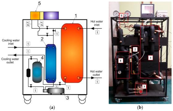
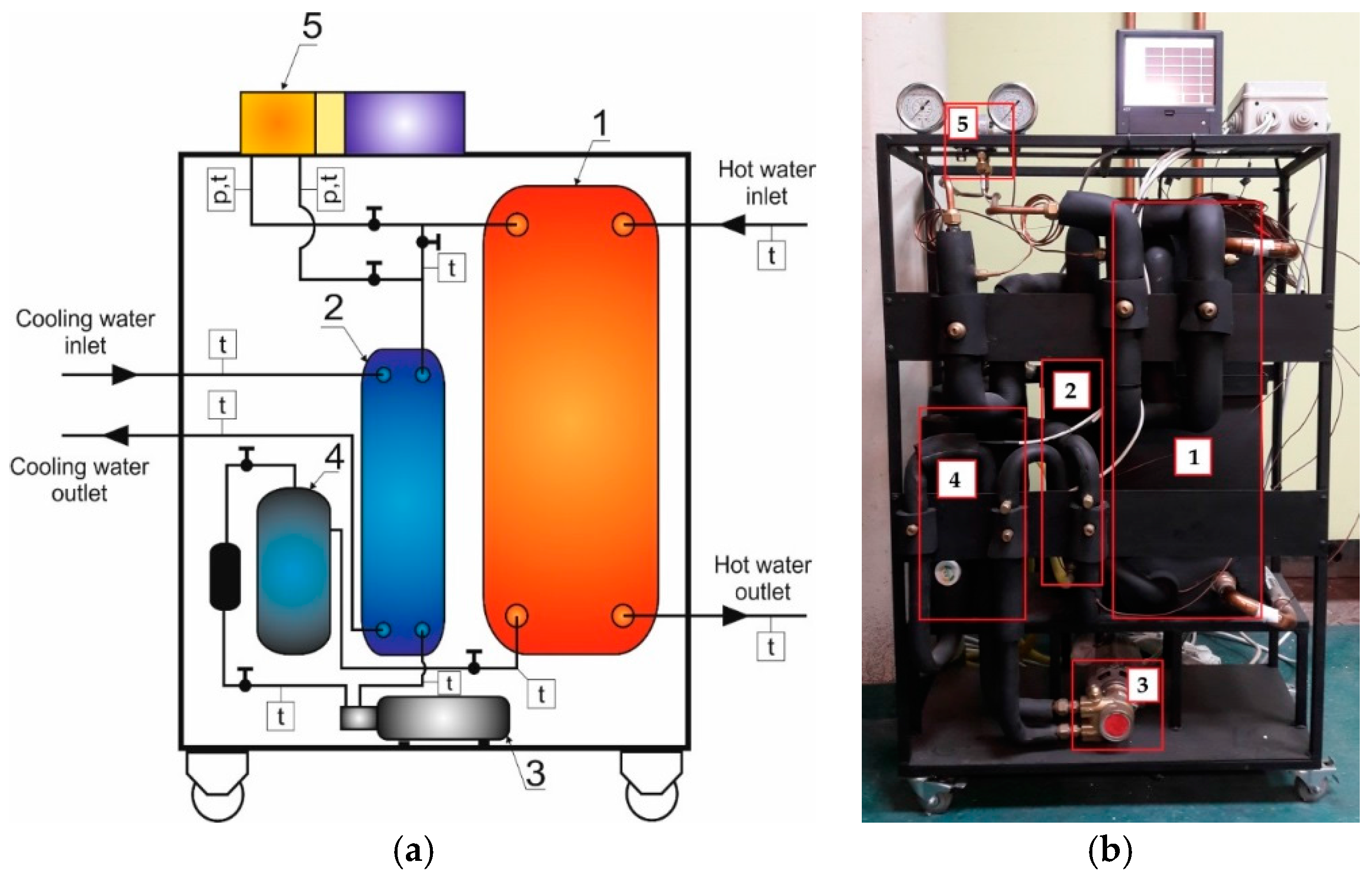
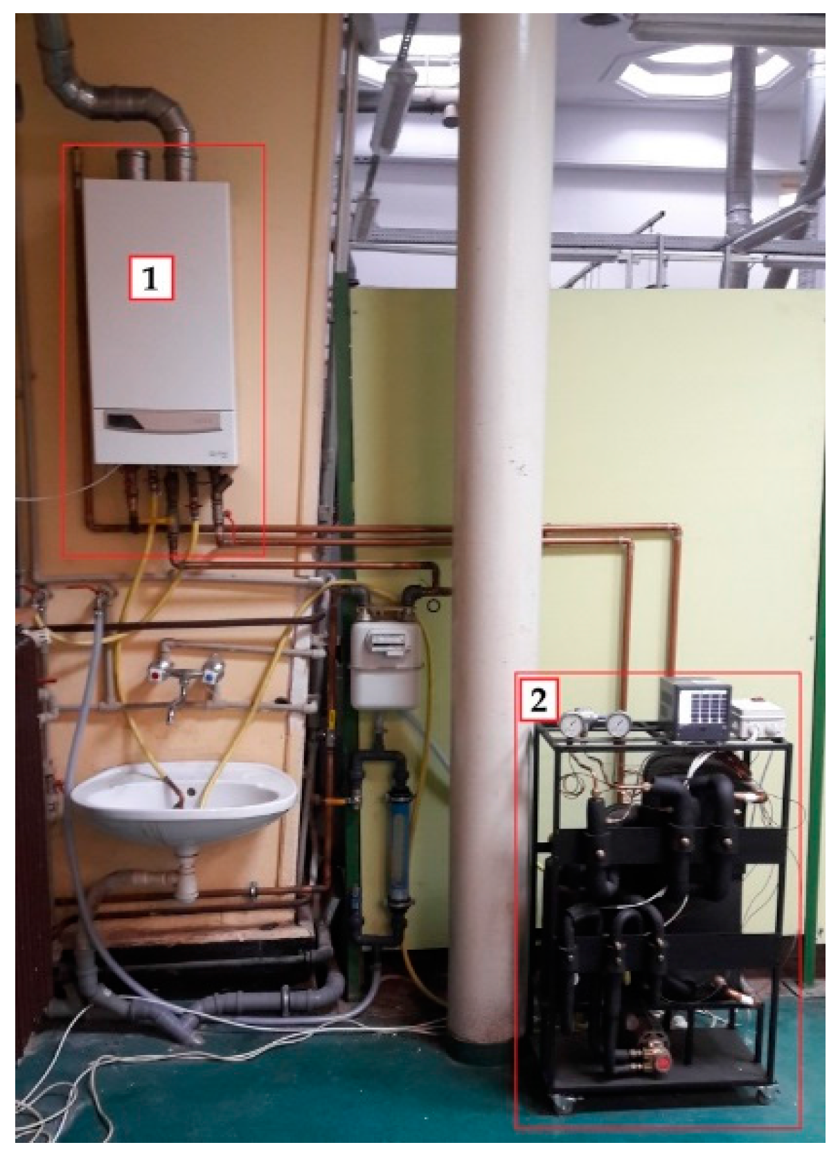
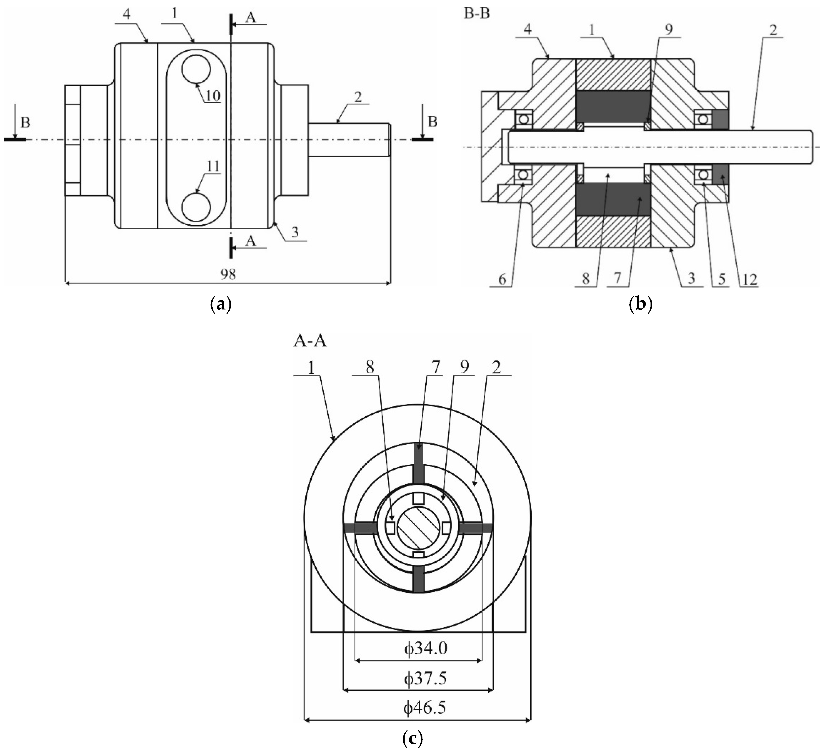
2.1. Description of the Test-Stand and the Multi-Vane Expander

The experimental test-stand (a prototype of a domestic combined heat and power (CHP) ORC system) was commissioned at the Laboratory of Thermodynamics and Thermal Properties of Materials of the Department of Thermodynamics, Theory of Machines and Thermal Systems at the Wroclaw University of Science and Technology in 2016. Figure 1a shows a simplified construction scheme of the test-stand. Figure 1b shows a general view of the test-stand. Figure 2 shows a general view of the test-system.
The test-stand was designed and realized in order to study the applicability of the different types of volumetric expanders in domestic ORC power systems. The authors are experimentally investigating (testing) applicability of the following three types of expanders: rotary lobe expander (featuring the maximal power of 3 kW), multi-vane expander with an elliptic cylinder (featuring the maximal power of 1.5 kW), and a micro multi-vane expander (featuring the maximal power of 300 W). The test-stand components are: a plate evaporator (1); a plate condenser (2); a working fluid pump (3); a reservoir of a working fluid (4); and a micro multi-vane expander (5). Pipelines are made of copper welded by a silver binder. The test-stand features the maximal thermal power of 18 kW. The electric power of the test-stand varies between 300 W and 3 kW and depends on the type of the tested expander, as well as on the system working conditions (i.e., heat source and heat sink temperature, working fluid flow and pressure). The overall test-stand efficiency ranges between 7% and 12%. The working fluid is R123 (Du Pont, Mississauga, ON, Canada). This working fluid was selected basing on its thermal properties (i.e., low pressures in the heat source temperature range; low boiling temperature under the atmospheric pressure tb = 27 °C, enabling the possibility of easily filling the system with the liquid-phase medium) and the authors’ good experiences resulting from use of this fluid in an earlier prototype of ORC power system [10,19]. The heat source for the test-stand is hot water from a gas boiler with a closed combustion chamber. The condenser is cooled by the cold water in the open cycle. The water temperature can be regulated in the range of 40–95 °C. This allows the simulation of different operational conditions of the system and the expander. Temperatures were measured with the use of T-type thermocouples, with accuracy of ±0.5%, connected to a digital microprocessor data acquisition system. Pressures were measured with the use of tube pressure gauges, with accuracy of ±1.6%. Rotational speed of the expander was measured with the use of laser tachometer, with accuracy of ±0.05%.
The working principle of the system can be described on the basis of Figure 1. The hot water from the gas boiler is pumped to the plate evaporator (1). The liquid working fluid (R123) is pumped (3) from the reservoir (4) to the plate evaporator (1), and it is heated by the hot water circulating between the plates. The hot pressurized vapor flows from the outlet of the evaporator (1) through a pipeline to the inlet of the multi-vane expander (5). After the expansion, the vapor flows to the plate condenser (2) and it is cooled by the cold water circulating between the plates. Then, the liquid flows to the reservoir (4) and the cycle is therefore complete.
The expansion device is a micro four-vane air motor. The expander was adapted for low-boiling working fluid, i.e., the vanes made of cured silicone doped with graphite, the seals made of Teflon, and stainless steel bearings were used. Figure 3 shows the simplified construction scheme of the expander.
The main expander components are: the cylinder (1) with an inner diameter of 37.5 mm and a length of 22.0 mm, the rotor (2) with an outer diameter of 34.0 mm and the pair of end covers (3 and 4). The rotor is mounted eccentrically in the cylinder on stainless steel rolling bearings (5 and 6). Eccentricity is equal to 1.75 mm. Vanes (7) are placed in perpendicular slots (8) milled in the rotor. The vanes are pressed to the cylinder surface with help of the ring (9). Thickness of a vane is equal to 1.5 mm. The expander is fed with working fluid vapor through the cylindrical inlet port (10) with an inner diameter of 8.5 mm. After the expansion, vapor flows through the outlet port (11) with an inner diameter of 8.5 mm. Figure 4 shows a general view of the expander.

2.2. The Experimental Description and Results

The aim of the experiment was obtaining a data needed for the validation of the 3D numerical model. Measurements were carried out for a variable heat source temperature (ths). Initially, the boiler was started and the water temperature was set to 45 °C on the boiler controller. Then the working fluid pump was started. The liquid R123 was pumped throughout all of the test-stand components, excluding the expander (via bypass pipeline). The temperature of the water was increased by increments of 10 °C. When the water was heated up to the required temperature, the vapor inlet of the expander was opened and the bypass pipeline was closed. When the system reached a steady-state, the measurements of the operational parameters were made. Then the vapor inlet of the expander was closed again and the bypass pipeline was opened. After cooling of the test-stand the experiment was repeated for the following values of the water temperature: 55 °C, 65 °C, 75 °C, and 85 °C. The experiment was performed for the working fluid pressure range of 2.0–5.2 bar. Table 1 reports the experimental results. Table 2 shows the values of the thermodynamic properties of the working fluid at the inlet and at the outlet of the expander, the expander isentropic work ls, the expander indicated work li as well as the expander internal efficiency ηi. The values of the thermodynamic properties of the working fluid were evaluated using the NIST Refprop Software (Thermophysical Properties Division, National Institute of Standards and Technology, Boulder, CO, USA). The expander indicated work was calculated as the difference of the specific enthalpy of the working fluid at the inlet and at the outlet of the expander. The expander internal efficiency was calculated as a ratio of li/ls. During the experiments, the operation of the expander was kept under observation. It was found that the expander operation was smooth and proceeded continuously.
As can be observed in Table 2, the expander indicated work and efficiency change depending on the heat source temperature and the expansion ratio (σ = pin/pout). The minimal indicated work (2.22 kJ/kg) was observed for the heat source temperature of 45 °C and the expansion ratio of 1.54. In the second measurement point the indicated work increases with increasing heat source temperature and expansion ratio and reaches maximum value (4.18 kJ/kg). In the next measurement points, the indicated work decreases with increasing heat source temperature and expansion ratio. The expander’s internal efficiency varies in the range of ηi = 17.2%–58.3%. As can be observed in Table 2, progressive lowering the expander’s internal efficiency and indicated work is observed for higher values of the expansion ratio. This is the characteristic feature of the multi-vane expanders, resulting from the dependence of the indicated work on expansion ratio. Multi-vane expanders are characterized by the optimum value of the expansion ratio [19]. For the analyzed expander it is seen that the optimum expansion ratio is σ ≅ 2. Thus, increasing the working fluid pressure at the inlet of the expander results in decreasing the efficiency and power of the expander. This issue is comprehensively treated in [19].

3. Numerical Modelling

In order to simulate the expansion process, a three-dimensional numerical model has been prepared. Due to the expanders’ principle of operation, the calculations were performed in transient with use of moving boundary conditions. Thus, the numerical mesh had to be deformed at each time-step. The coordinates of a rotor and vanes’ boundary conditions were recalculated for each time-step and grid nodes were being moved into their new locations. This translation between coordinate systems has to be represented in the governing equations solved.

3.1. The Governing Equations

In considered non-isothermal, compressible and turbulent flow, standard Navier–Stokes equations were modified to incorporate mesh motion (Equations (1)–(3)). The U vector, is relative velocity vector (U = UfluidUwalls, where Ufluid is the fluid velocity and Uwalls is the wall velocity).
Continuity equation:
ρ t + · ( ρ U ) = 0
Momentum equation:
ρ U τ + · ( ρ U U ) = p + · [ μ ( U + U T ) ]
Energy equation:
( ρ h ) t + · ( ρ U h ) = · ( k T )
In the model, additional geometric conservation law (Equation (4)) was introduced [22]. The modifications of governing equations assure that only boundary conditions affect the flow, regardless the internal mesh deformation. Otherwise, a dimension change of the counter volume would result in artificial mass sources appearance. The discretized form of above equations was solved using the commercial solver Ansys CFX (ANSYS, Inc., Canonsburg, PA, USA).
Global conservation law:
d d t Ω d Ω + S U walls n d S = 0
where Ω is the volume of the numerical cell, S is the area of the numerical cell wall, Uwalls is the wall velocity, and n is the wall normal vector.

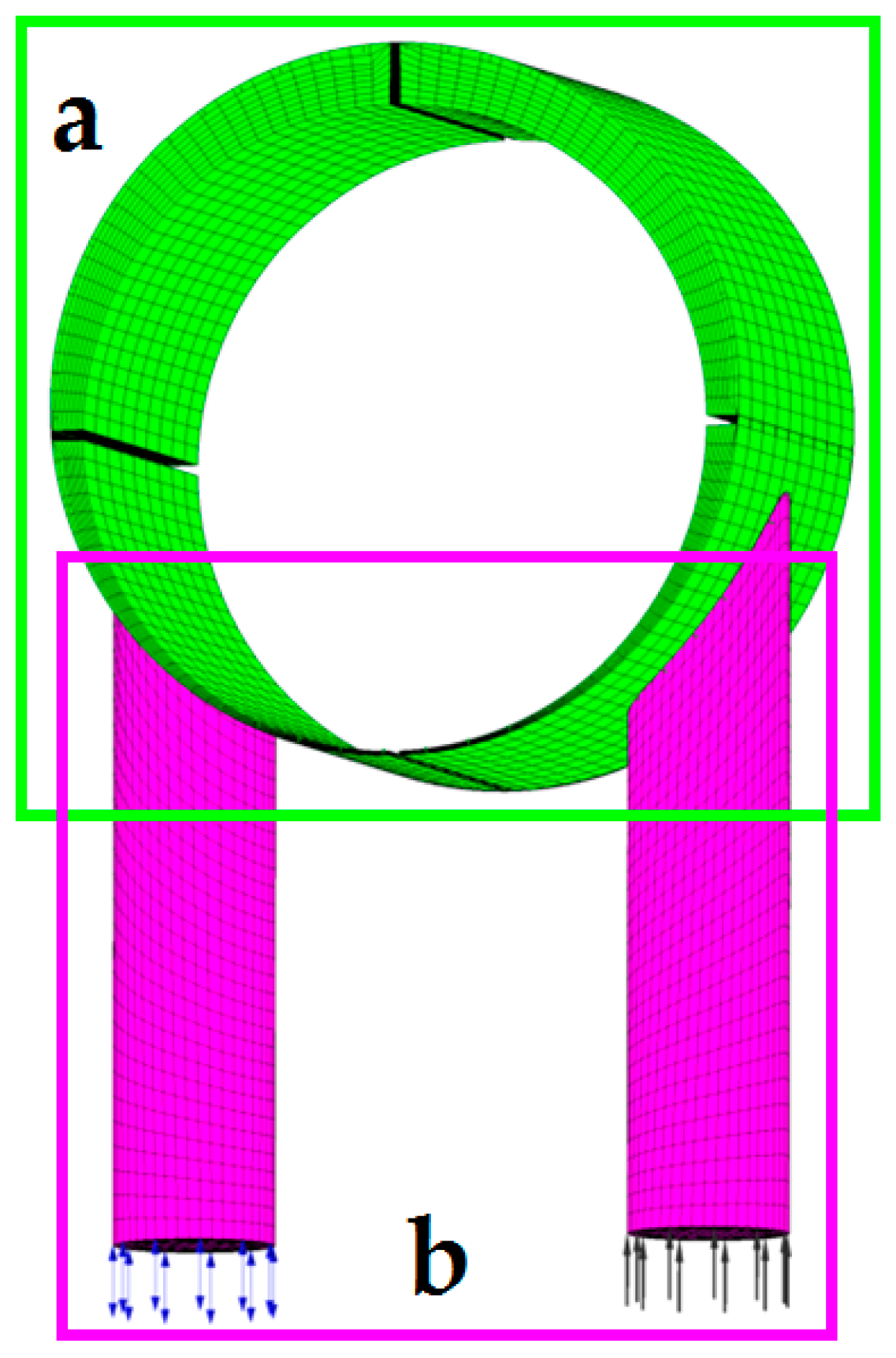
3.2. The Computational Grid

Based on the preliminary calculations, the numerical grid consisting of 34,026 hexagonal elements was chosen. The mesh independence study showed that double increase of the mesh resolution does not improve the quality of results. The grid was divided into two computational domains (connected with an interface boundary condition [22]): stationary inlet and discharge ports, and rotating/deforming working chambers (Figure 5). Thirty five percent of the mesh nodes was at the rotor domain. While the mesh deformation is slight, the grid quality and orthogonality were preserved during the calculations. The mesh inflation layers were used towards the expander vanes, walls and interfaces in order to ensure a proper solution resolution. It is important since in the model, a clearance between vanes tips and the outer wall has been taken into account. The constant value of the clearance for each simulation was assumed, and it was set to 40 μm. This allowed the modelling of all of the working chambers as one domain. The advantage of such an approach that it takes the inner radial leakage phenomenon into account. The leakage in the axial direction was not included in the analysis. This is justified by the small area of the side tips of the vanes with the expander end-covers [20]. Thus, this is considered to have a minor impact on the results.

3.3. Model Details

Specified pressure and temperature inlet boundary conditions were used (Table 3). Inlet parameters, as well as the rotor rotational speed and outlet pressure, were taken from the experiment. Time-dependent working fluid thermal properties, in working chambers and at the discharge, were solved. The walls were considered adiabatic. This is justified by a small difference in temperature between the medium and the ambient and the high rotational speed. Time step size was set to τ = 5.5 × 10⁻⁵ s. For the rotational speed of 3000 rpm it represents about 1 degree of rotor revolution. The total operation time of the expander in Computational Fluid Dynamics (CFD) analysis was 0.1 s (5 full revolutions of the rotor). Calculations have been performed on the BEM supercomputer (Wroclaw Centre for Networking and Supercomputing, Wrocław, Poland) in parallel mode using four Intel Xeon E5-2670 v3 2.3 GHz processors (Intel, Santa Clara, CA, USA) and they lasted for about 16 h per simulation.
The flow was modeled as single-phase. Thermal properties of R123 were calculated using two models. The first was an ideal gas equation, where density and enthalpy were calculated with use of R123 molar mass MR123 = 152.93 kg/kmol.
The second model used was the Redlich–Kwong real gas equation of state with Soave modification. The equations take into account the attractive forces between the molecules and are supplemented with a volume correction. The heat capacity was calculated using a fourth order polynomial. Soave–Redlich–Kwong equation is able to deal with phase behavior of mixtures in the proximity of the critical point [23]. Thus, this model was selected because the saturated conditions of the medium were expected.
The experimental mass flow rate was estimated with Equation (5). The results were compared to the output from the numerical model. The proposed expression is valid assuming negligible vanes volumes compared to the machine volume:
m ˙ = 4 π R e L n ( ρ in + ρ out 2 )
where R is the radius of the cylinder, e is the eccentricity, L is the length of the cylinder, n is the rotational speed, and ρin and ρout is the working fluid density at the inlet and the outlet of the expander, respectively.

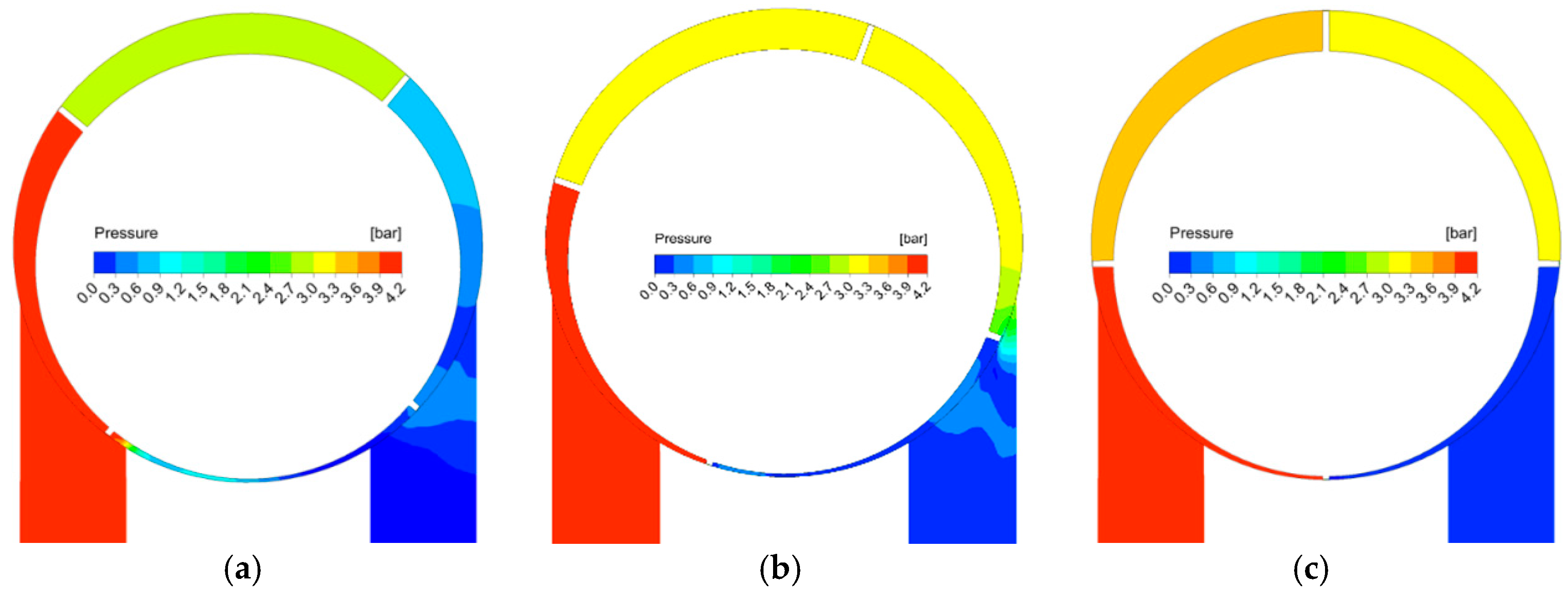
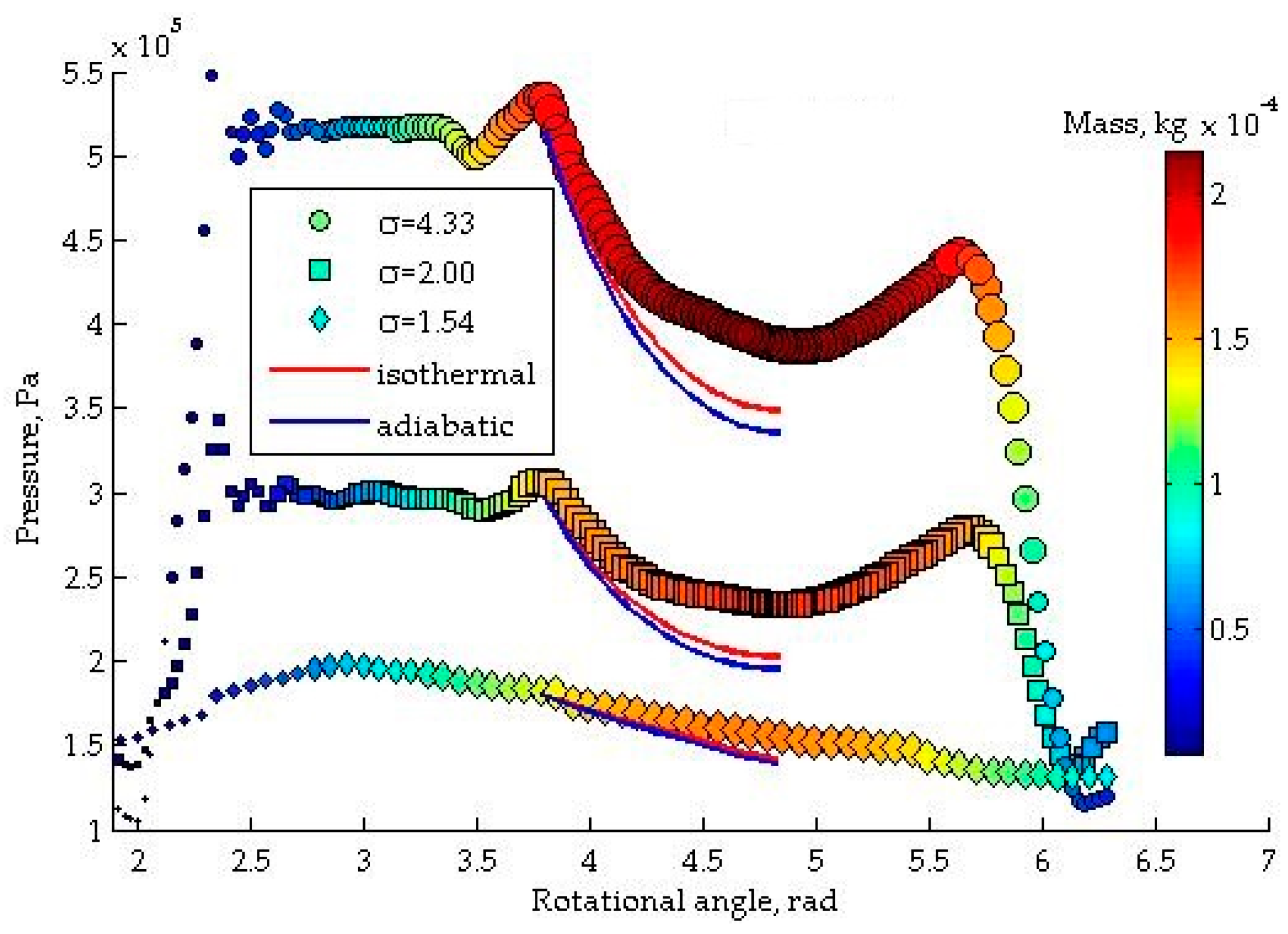
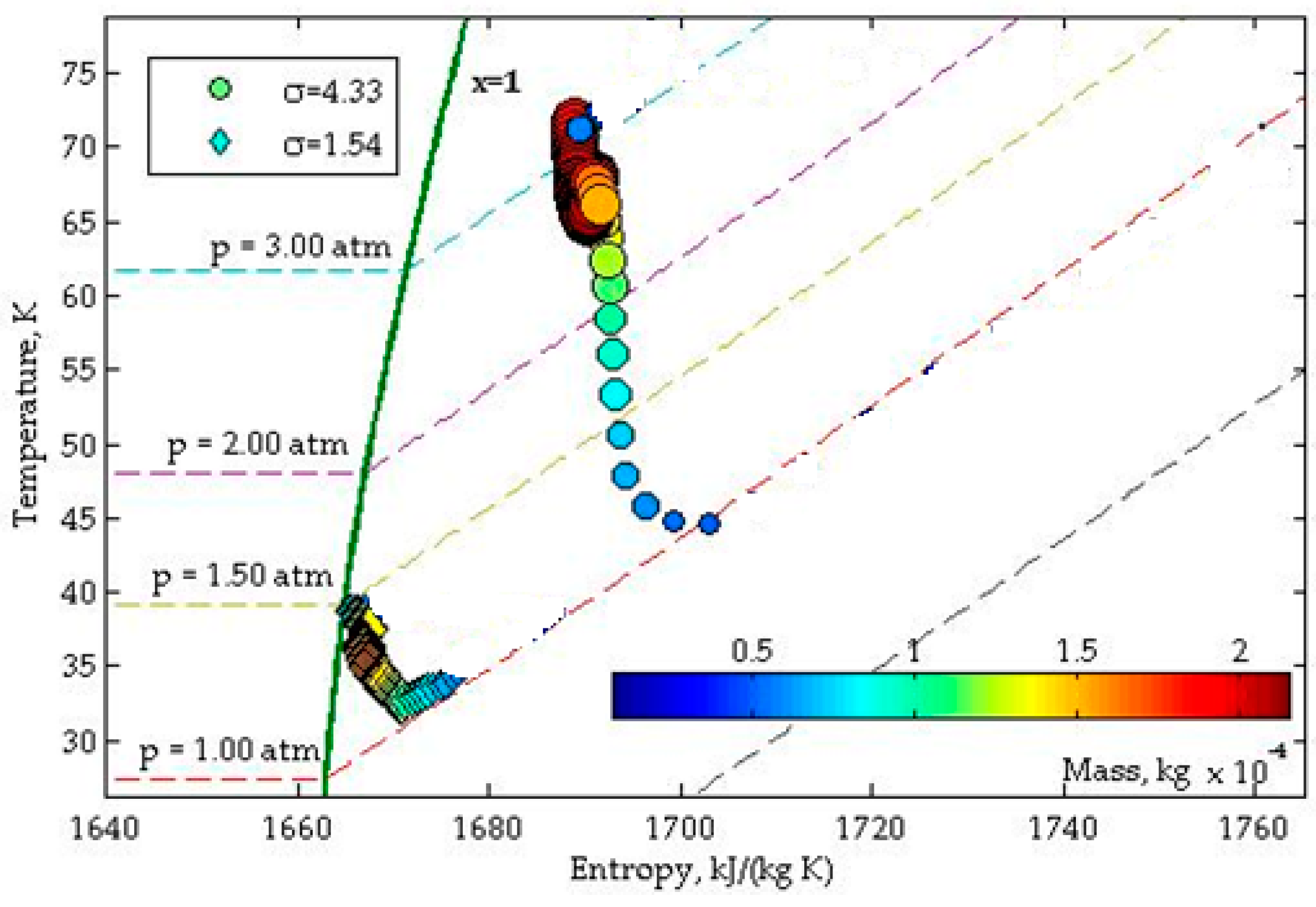
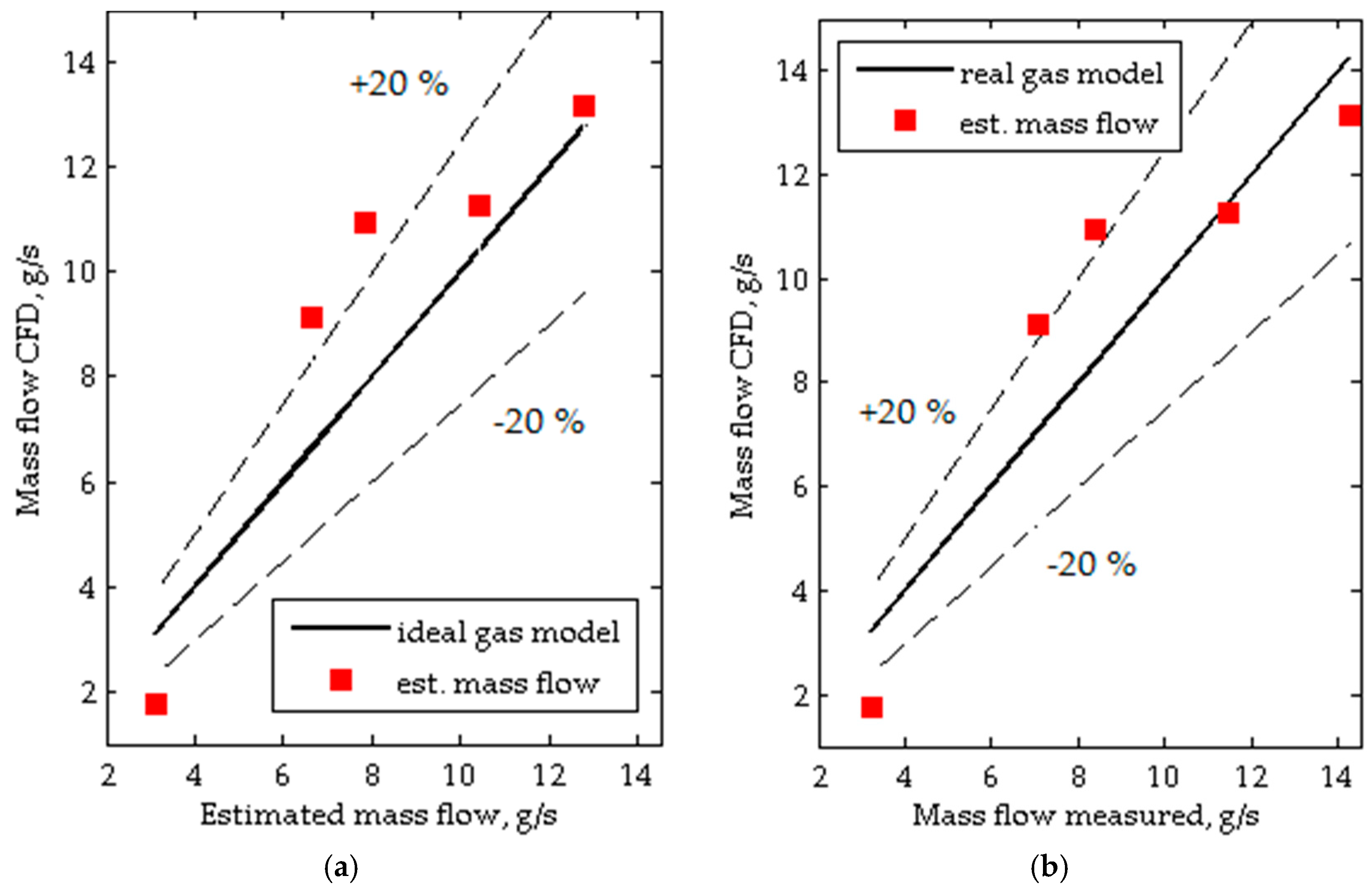
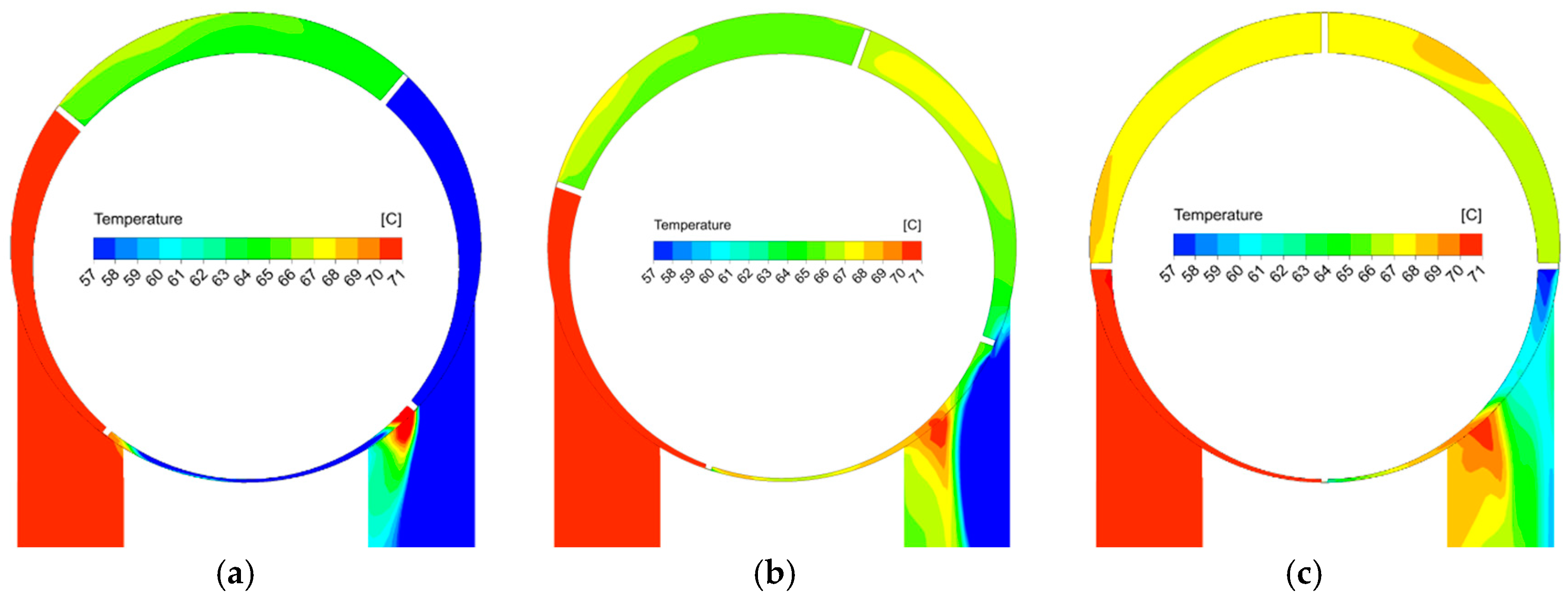
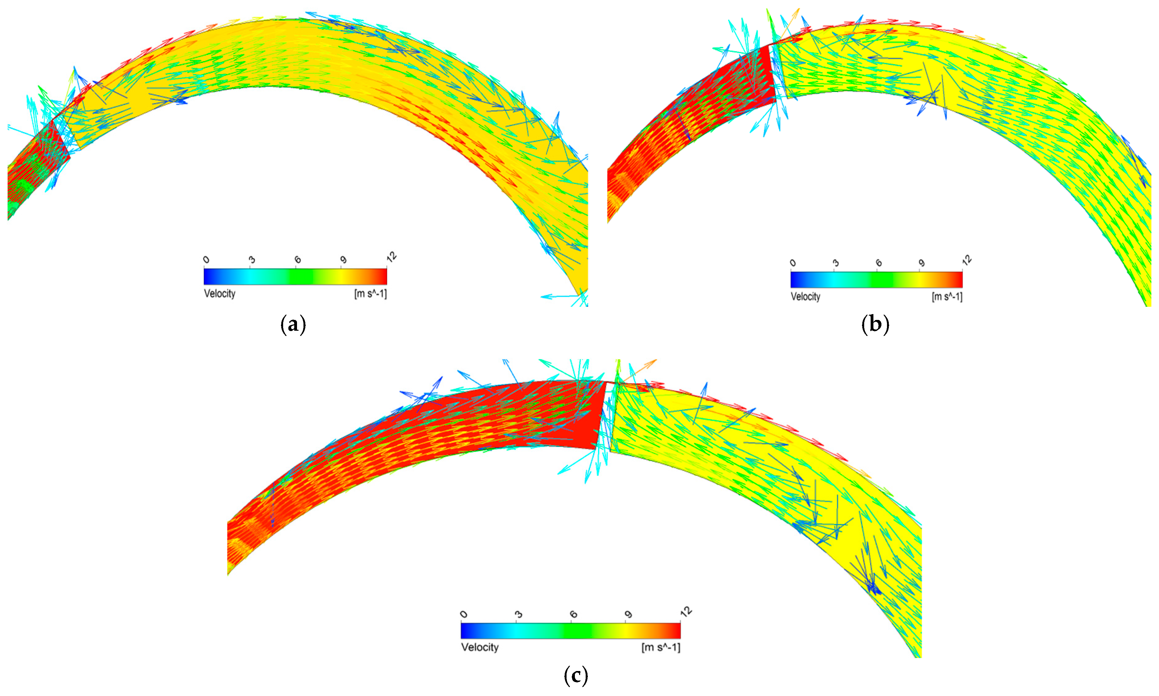
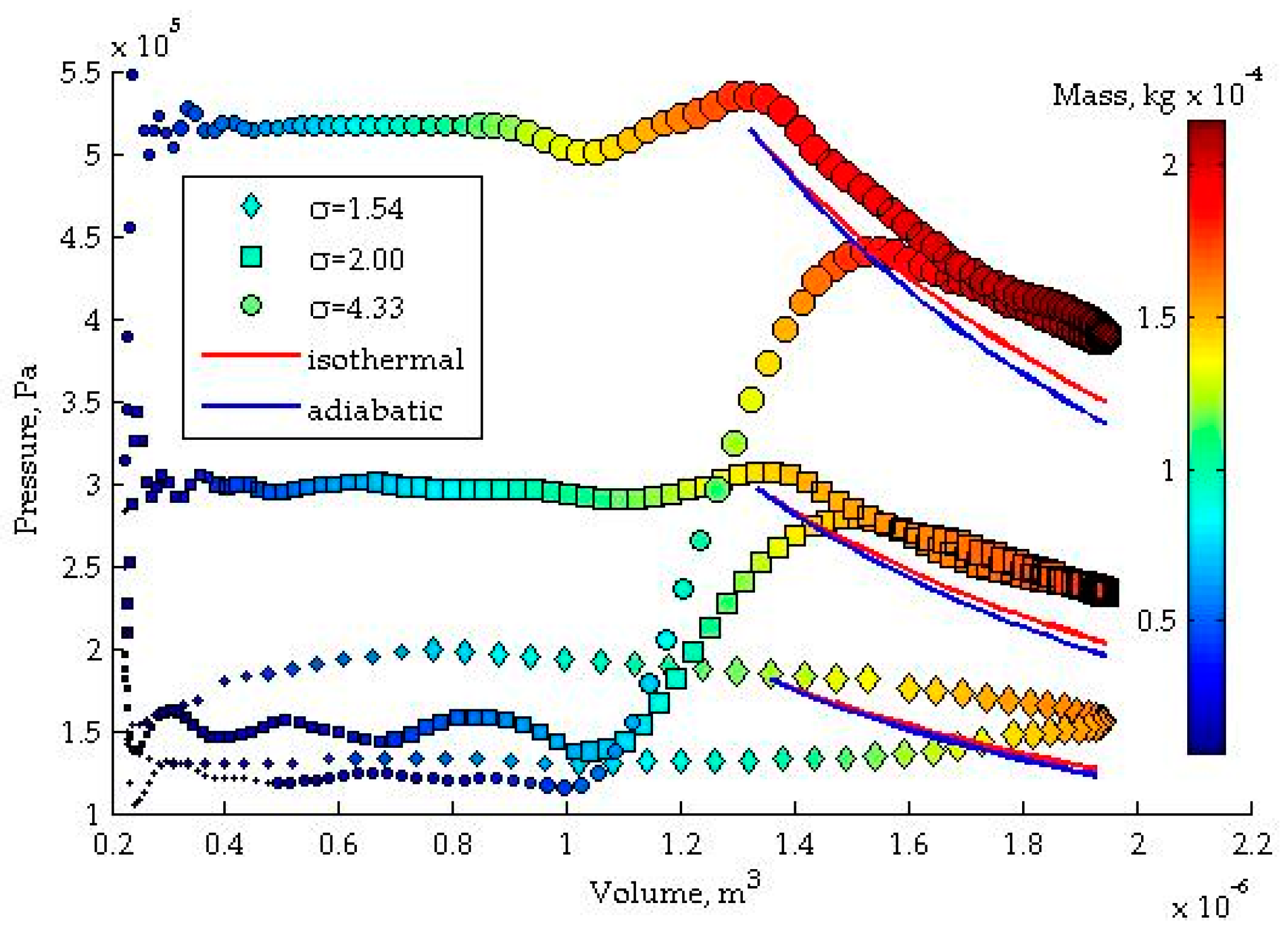
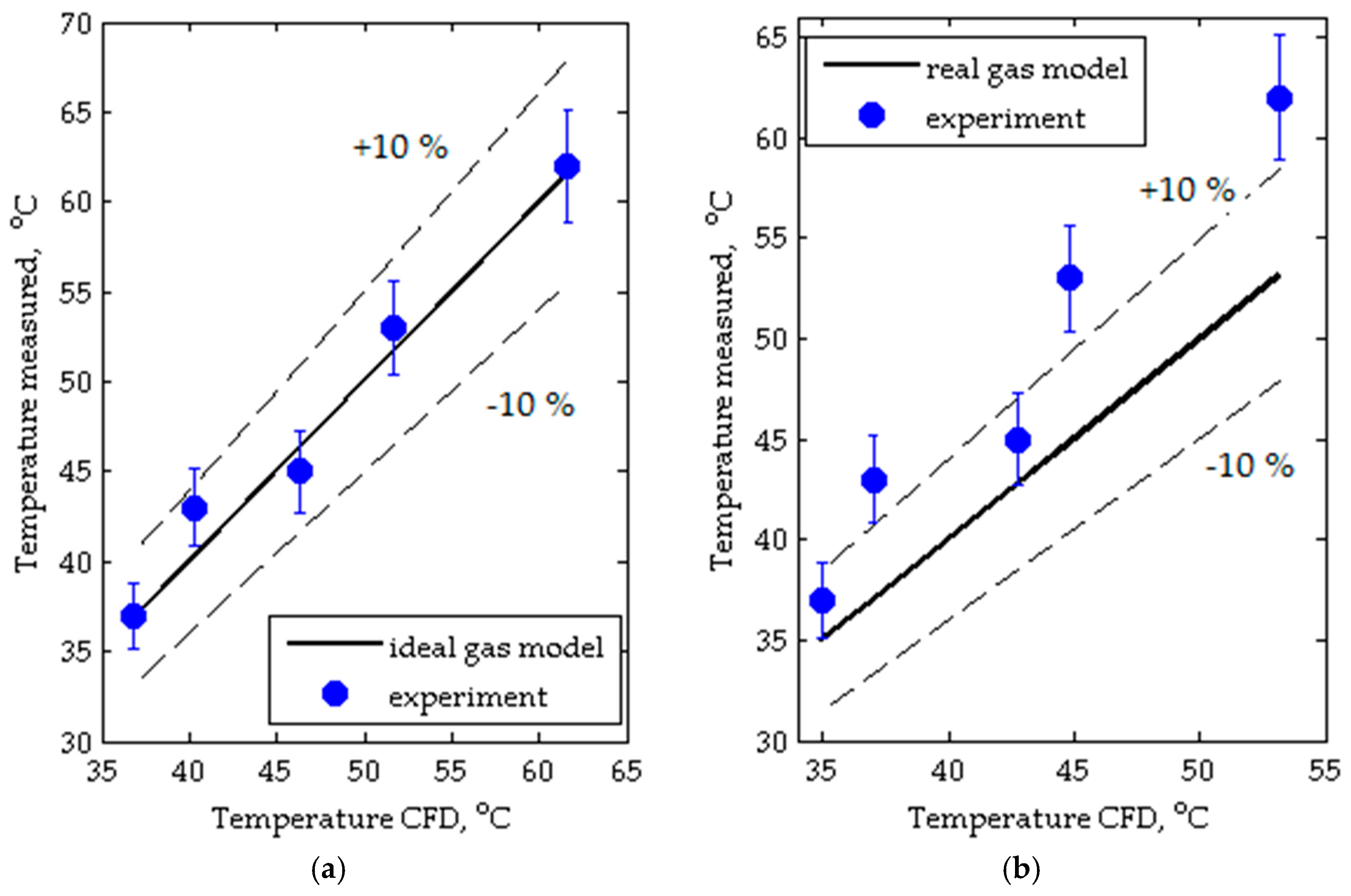
4. Results and Discussion

The output from the model were time-dependent distributions of working fluid thermal properties in four working chambers. Although the calculations covered five full shaft revolutions, the results were periodically stable after the first full revolution. The solution convergence for the governing equations was always under 10−4 Root Mean Square (RMS) criterion. Moreover, a mass imbalance between the inlet and outlet ports was under 0.1% during the cycle. This suggests that the geometric conservation law (Equation (4)) was satisfied and no artificial mass sources occurred inside the deformed mesh domain.
Figure 6 and Figure 7 show exemplary temperature and relative pressure distributions for the value of expansion ratio σ = 4.3 and for the angle of rotor rotation (ϕ) varying in the range of 0–2π, respectively. These figures correspond to measurement No. 5 (Table 1). The temperature and pressure fields inside each working chamber are almost uniform (differences less than 3 K and 0.3 bar, respectively, are observed).
In Figure 6 it also may be noticed that temperature field disturbances are likely to occur in the regions close to the vanes. This is caused by the working fluid leakage between working chambers. This effect is also visible in the temperature field in the outlet port. The gas with high values of thermodynamic properties pin and Tin flows into the rotating chamber through the inlet port. A portion of this gas leaks through the gap between a rotor and the cylinder to the outlet port. It mixes with the gas in the outlet port raising its temperature. This phenomenon is reflected in Figure 7a, where the disturbances of pressure field in the outlet port, caused by this leakage, are visible. The leakages between vanes tips and the cylinder negatively influence the expander operation and its efficiency. These leakages are characteristic for sliding-vane machines but their negative influence can be limited by proper machine design, i.e., arrangement of the inlet and the outlet ports as well as “steering edges” and increasing the number of vanes [19]. Even more, insight into the issue may be found in Figure 8 where velocity vectors are presented. Nozzle effect and movement of the vanes result in highly rotational flow field in the working chamber. Consequently, a recirculation zone is clearly visible.
The mean pressure evolution inside a working chamber is presented in Figure 9. The size of the symbol and its color indicate the mass of the medium inside the chamber volume at given time. Three main cycle phases may be observed: filling, expansion, and evacuation. The characteristic is consistent with the results of Jia et al. [24] who tested and modelled similar multi-vane machine. The distinctive feature observed in the obtained characteristic [24] is the pressure growth before the end of the expansion. This negative feature results from symmetric design of the analyzed expander and improper arrangement of the outlet port. Non continuous expansion significantly and negatively influences the expander power output. In the analyzed expander, four working chambers coexist in one moment in time. A single working chamber changes its volume continuously during one full rotor revolution. In the beginning of the revolution, the working chamber volume is small and it increases with the rotor movement. The maximum volume of the working chamber is reached in the half of the shaft revolution. During the next part of the shaft revolution, the working chamber volume decreases again. Thus, the working fluid is first expanded and then re-compressed (aforementioned pressure growth in Figure 9) before the work cycle is completed. In the properly designed expander the recompression should be minimized, this effect can be achieved by changing the expander design to asymmetric or changing the outlet port placement [10]. As it can be observed in Figure 9, after the re-compression the working fluid is rapidly evacuated from the working chamber (ϕ = 3.8–4.3 rad) through the outlet port without further energy conversion. The re-compression effect vanishes for σ < 1.6 as a result of lower rotational speed of the expander.
Figure 10 shows an indicator diagram depicted in the pV diagram. It is seen that only small part of the gas energy was converted into mechanical power as a result of low pressure drop during the expansion caused by rapid gas evacuation from the working chamber. This is due to the above-described issues of expander construction. The results show the need of research on expander geometry optimization.
Figure 11 shows the expansion process in the Ts plane. By analyzing Figure 11 it is seen that during the expansion entropy increases as the numerical model takes into account viscosity of the fluid. Resulting expansion is polytropic and limited in a 65–75 °C temperature range (red circles in Figure 11). However, as it was mentioned earlier, the design of the expander causes limited enthalpy drop. The expansion process should proceed to the lower pressure and corresponding temperature at the outlet. The visible temperature increase, during the expansion, corresponds to the re-compression process observed in pV chart (Figure 10).
Additionally, the time average discharge temperature and mass flow obtained numerically were compared with the experimental results in Figure 12 and Figure 13, respectively. As shown in Figure 12, the ideal gas model predictions were under 5% deviation from the measurements. In case of Redlich–Kwong method, temperatures are lower in the whole range of pressure ratios studied, although they are still in the 15% variance limit. Numerically obtained mass flow rates are presented in Figure 13 and compared with theoretical ones. The results show good agreement between both models used and theory. Except the lowest pressure ratio, all of the models’ predictions are in a 30% accuracy range.

5. Summary and Conclusions

This paper presents a study providing the experimental and numerical analyses on the rotary vane expander operating conditions in a micro-ORC system. Such systems are promising for application as energy converters in a domestic cogeneration of heat and electric power. Experiments were performed on a prototype of a domestic micro-power ORC system. Numerical analysis was carried out on three-dimensional model of the expander. The model was developed based on the geometrical data obtained by complete disassembly of the tested machine. Numerical analysis of the expander operation was performed in ANSYS CFX. The input data for numerical analyses were the thermodynamic parameters measured on the test-stand.
The experiment demonstrated that commercially available multi-vane pneumatic engines can be adopted to micro-ORC systems if the sealing and bearing issues are properly solved. During the experiments, the operation of the multi-vane expander was kept under observation. The operation was smooth and silent.
The results of the numerical analyses showed the distributions of the pressure, velocity vectors and the temperature of R123 in the expander working chambers. Modelling results show good agreement with experimentally obtained data. In the analyzed range of operational parameters, the ideal gas model was proved to be accurate for the global machine parameters. The real gas effects were found to be negligible since a more complex, real gas model gives compatible results to the ideal model. Moreover, the results showed few disadvantages of the tested expander. Namely, it was found that the symmetric expander design negatively influences the expansion process as the working fluid is first expanded and then re-compressed during the operational cycle. This results in significant decrease of a work performance. Moreover, it was found that the leakages between the vane tips and cylinder negatively influence the expander operation as the gas from the inlet port leaks to the outlet port and mixes with the gas evacuated from the expander. These effects can be eliminated by optimizing the expander design. The optimization of the expander design should include the change of the symmetrical design to asymmetrical in order to increase the volume of the working chambers in the final stage of the operation cycle. This solution avoids the re-compression of the gas after the expansion. The rotor diameter should also be lower and the length of the cylinder should be larger. This would increase volume of the working chambers and in turn results in the increase of the expander power.
Encouraged by the results of the experiment and numerical simulation, the authors designed a new ORC-dedicated multi-vane expander. The construction of the prototype is underway. The authors are currently working on further numerical and experimental analyses concerning the application of the volumetric expanders to domestic ORC systems.

Acknowledgments

Calculations have been carried out using BEM supercomputer resources provided by Wroclaw Centre for Networking and Supercomputing (http://wcss.pl).

Author Contributions

Piotr Kolasiński conceived and designed the test-stand and the experiments; Przemysław Błasiak and Józef Rak conceived and designed the numerical model; Piotr Kolasiński, Przemysław Błasiak and Józef Rak performed the experiments; Piotr Kolasiński, Przemysław Błasiak and Józef Rak analyzed the data; Piotr Kolasiński, Przemysław Błasiak and Józef Rak wrote the paper.

Conflicts of Interest

The authors declare no conflict of interest.

References

  1. Asif, M.; Muneer, T. Energy supply, its demand and security issues for developed and emerging economies. Renew. Sustain. Energy Rev. 2007, 11, 1388–1413. [Google Scholar] [CrossRef]
  2. Meij, R. Trace element behavior in coal-fired power plants. Fuel Process. Technol. 1994, 39, 199–217. [Google Scholar] [CrossRef]
  3. Dinusha Rathnayaka, A.J.; Potdar, V.M.; Dillon, T.S.; Kuruppu, S. Formation of virtual community groups to manage prosumers in smart grids. Int. J. Grid Util. Comput. 2015, 6, 47–56. [Google Scholar] [CrossRef]
  4. Lund, H. Renewable Energy Systems, 2nd ed.; Academic Press: Manhattan, NY, USA, 2014. [Google Scholar]
  5. Neville, R.C. Solar Energy Conversion, 2nd ed.; Elsevier: Amsterdam, The Netherlands, 1995. [Google Scholar]
  6. Hau, E. Wind Turbines—Fundamentals, Technologies, Application, Economics; Springer: Berlin, Germany, 2013. [Google Scholar]
  7. Saidur, R.; Abdelaziz, E.A.; Demirbas, A.; Hossain, M.S.; Mekhilef, S. A review on biomass as a fuel for boilers. Renew. Sustain. Energy Rev. 2011, 15, 2262–2289. [Google Scholar] [CrossRef]
  8. Revankar, S.T.; Majumdar, P. Fuel Cells: Principles, Design, and Analysis; CRC Press: Boca Raton, FL, USA, 2014. [Google Scholar]
  9. Dinçer, I.; Rosen, M.A. Thermal Energy Storage: Systems and Applications; John Wiley & Sons: Chichester, UK, 2002. [Google Scholar]
  10. Kolasiński, P. The influence of the heat source temperature on the multivane expander output power in an organic Rankine cylce (ORC) system. Energies 2015, 8, 3351–3369. [Google Scholar] [CrossRef]
  11. Ahmadi, P.; Dincer, I.; Rosen, M.A. Development and assessment of an integrated biomass-based multi-generation energy system. Energy 2013, 56, 155–166. [Google Scholar] [CrossRef]
  12. Tchanche, B.F.; Lambrinos, Gr.; Frangoudakis, A.; Papadakis, G. Low-grade heat conversion into power using organic Rankine cycles—A review of various applications. Renew. Sustain. Energy Rev. 2011, 15, 3969–3979. [Google Scholar] [CrossRef]
  13. Bao, J.; Zhao, L. A review of working fluid and expander selections for organic Rankine cycle. Renew. Sustain. Energy Rev. 2013, 24, 325–342. [Google Scholar] [CrossRef]
  14. Mago, P.J.; Luck, R. Energetic and exergetic analysis of waste heat recovery from a microturbine using organic Rankine cycles. Int. J. Energy Res. 2013, 37, 888–898. [Google Scholar] [CrossRef]
  15. Kozanecki, Z.; Łagodziński, J. Magnetic thrust bearing for the ORC high-speed microturbine. Solid State Phenom. 2013, 198, 348–353. [Google Scholar] [CrossRef]
  16. Liu, H.; Qiu, G.; Shao, Y.; Daminabo, F.; Riffat, S.B. Preliminary experimental investigations of a biomass-fired micro-scale CHP with organic Rankine cycle. Int. J. Low-Carbon Technol. 2010, 5, 81–87. [Google Scholar] [CrossRef]
  17. Cotana, F.; Messineo, A.; Petrozzi, A.; Coccia, V.; Cavalaglio, G.; Aquino, A. Comparison of ORC turbine and stirling engine to produce emectricity from gasified poultry waste. Sustainability 2014, 6, 5714–5729. [Google Scholar] [CrossRef]
  18. Kozanecki, Z.; Kozanecka, D.; Klonowicz, P.; Łagodziński, J.; Gizelska, M.; Tkacz, E.; Miazga, M.; Kaczmarek, A. Oil-Less Small Power Turbo-Machines; Institute of Fluid-flow Machinery Publishing: Gdańsk, Poland, 2014. [Google Scholar]
  19. Gnutek, Z.; Kolasiński, P. The application of rotary vane expanders in organic Rankine cycle systems—Thermodynamic description and experimental results. J. Eng. Gas Turbines Power 2013, 135. [Google Scholar] [CrossRef]
  20. Montenegro, G.; Della Tore, A.; Fiocco, M.; Onorati, A.; Benatzky, C.; Schlager, G. Evaluating the performance of rotary vane expander for small scale organic Rankine cycles using CFD tools. Energy Procedia 2014, 45, 1136–1145. [Google Scholar] [CrossRef]
  21. Montenegro, G.; Della Tore, A.; Onorati, A.; Broggi, D.; Schlager, G.; Benatzky, C. CFD simulation of a sliding vane expander operating inside a small scale ORC for low temperature waste heat recovery. In Proceedings of the 9th OpenFOAM Workshop, Zagreb, Croatia, 23–26 June 2014. [CrossRef]
  22. Ansys CFX Theory Guide; ANSYS, Inc.: Canonsburg, PA, USA, 2014.
  23. Soave, G. Equilibrium constants from a modified Redlich-Kwong equation of state. Chem. Eng. Sci. 1972, 27, 1197–1203. [Google Scholar] [CrossRef]
  24. Jia, X.; Zhang, B.; Yang, B.; Peng, X. Study of a rotary vane expander for the transcritical CO2 Cycle—Part II: Theoretical modeling. HVACR Res. 2009, 15, 689–709. [Google Scholar] [CrossRef]
Figure 1. The simplified construction scheme of the test-stand and a general view of the test-stand. (a) The simplified construction scheme of the test-stand; (b) A general view of the test-stand: (1) plate evaporator; (2) plate condenser; (3) working fluid pump; (4) working fluid reservoir; and (5) multi-vane expander.
Energies 09 00606 g001
Figure 2. A general view of the test-system. 1: gas central heating boiler; 2: domestic organic Rankine cycle (ORC) prototype.
Energies 09 00606 g002
Figure 3. The simplified construction scheme of the expander. (a) General view; (b) longitudinal section; and (c) transverse cross-section (1: cylinder; 2: rotor; 3 and 4: end covers; 5 and 6: rolling bearings; 7: vane; 8: vane slot; 9: ring; 10: inlet port; 11: outlet port; 12: shaft sealing).
Energies 09 00606 g003
Figure 4. A general view of the expander.
Energies 09 00606 g004
Figure 5. The numerical domains and the mesh. (a) Suction and discharge and (b) rotor domain.
Energies 09 00606 g005
Figure 6. The temperature distribution inside the expander for expansion ratio σ = 4.3. (a) ϕ = 1.50π; (b) ϕ = 1.75π and (c) ϕ = 2.00π (ideal gas model).
Energies 09 00606 g006
Figure 7. The relative pressure distribution inside the expander for expansion ratio σ = 4.3. (a) ϕ = 1.50π; (b) ϕ = 1.75π and (c) ϕ = 2.00π (ideal gas model).
Energies 09 00606 g007
Figure 8. Velocity vectors in a working chamber with visible recirculation zone. (a) ϕ = 1.50π; (b) ϕ = 1.75π and (c) ϕ = 2.00π (ideal gas model).
Energies 09 00606 g008
Figure 9. Pressure evolution inside the working chamber during the expansion process.
Energies 09 00606 g009
Figure 10. The pressure–volume diagram for an ideal gas model. Dot size represents the medium mass inside the working chamber.
Energies 09 00606 g010
Figure 11. Ts diagram for an ideal gas model.
Energies 09 00606 g011
Figure 12. Numerical temperature deviation from the measured values. (a) Ideal gas model; and (b) real gas model.
Energies 09 00606 g012
Figure 13. Comparison between numerical and the mass flow rate estimates (Equation (5)) for different pressure ratios. (a) Ideal gas model; and (b) real gas model.
Energies 09 00606 g013
Table 1. The experimental results.
No.ths (°C)pin (bar)tin (°C)pout (bar)tout (°C)n (rev/min)
1452.039.01.337.0700
2552.546.01.237.03280
3653.052.01.545.03300
4754.260.01.253.02900
5855.271.01.262.02950
Table 2. Thermodynamic parameters of R123 at the inlet and at the outlet of the expander and values of the expander indicated work and internal efficiency.
No.σhinsinhouthout ssoutlsliηi
kJ/kgkJ/kgKkJ/kgkJ/kgkJ/kgKkJ/kgkJ/kg(-)
11.54404.941.665403.98402.711.6692.220.960.431
22.08409.121.666404.94401.951.6767.174.180.583
32.00412.691.668408.91406.041.6776.643.780.569
43.50417.41.671413.92403.251.70414.153.470.246
54.33423.81.675420.47404.471.72419.333.320.172
Table 3. Numerical simulation parameters.
ParameterValueRemarks
Properties at the inletpin, TinFrom measurements
Properties at the outletpoutFrom measurements
Rotational speednFrom measurements
Time step5.5 × 10−5 s1 degree of revolution
Total time0.1 s5 full revolutions
Turbulence modelk-epsilonStandard model
Wall heat transferAdiabatic-
Vane-to-wall clearance40 μm-

