
Green Material Prospects for Passive Evaporative Cooling Systems: Geopolymers

Abstract
:
1. Introduction
2. Evaporative Cooling Systems
2.1. Direct Evaporative Systems
2.2. Indirect Evaporative Systems
2.3. Modified Evaporative Coolers
3. Potential Porous Materials
3.1. Ceramics
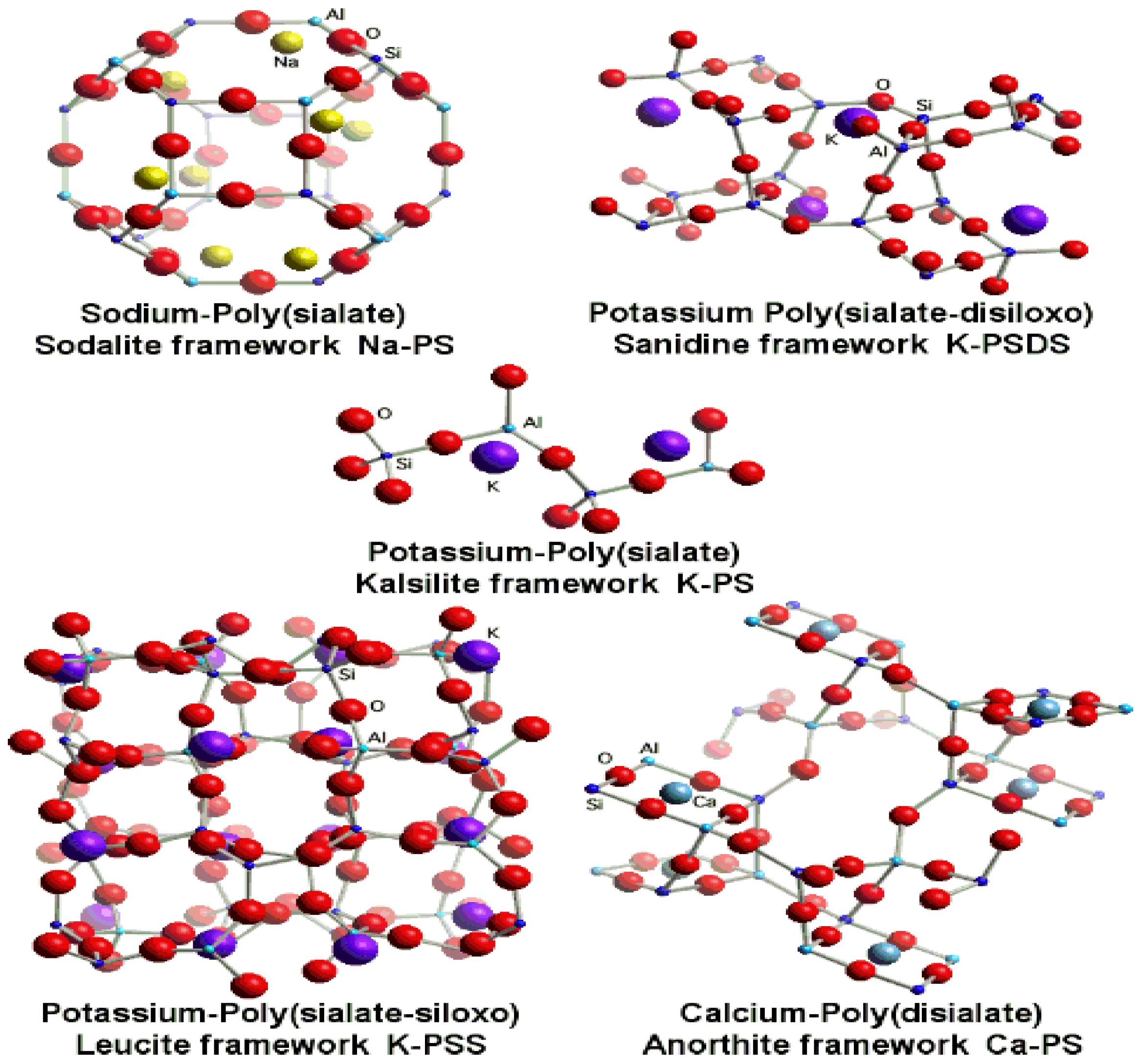
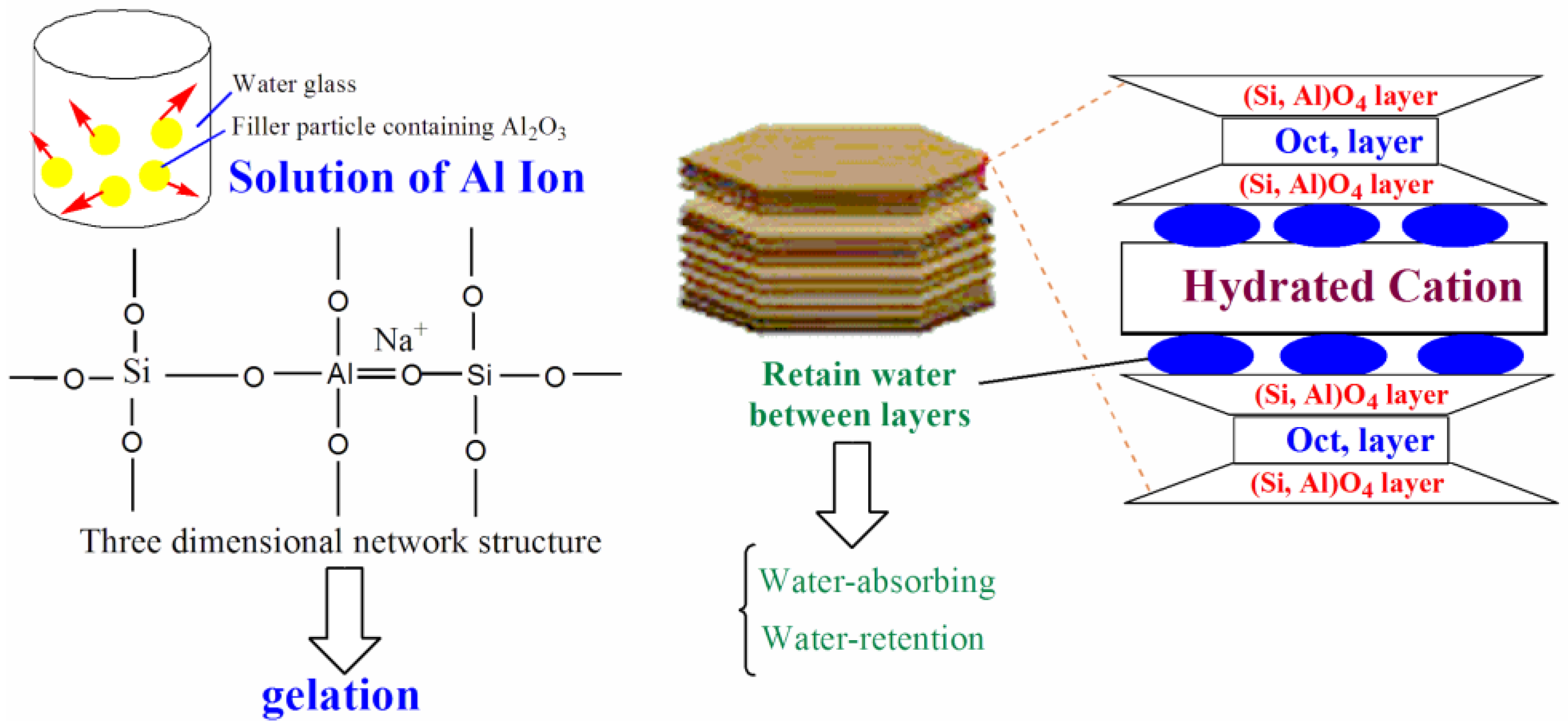
3.2. Geopolymers

 .
.
3.2.1. Application of Byproducts and Waste Products as Potential Raw Materials for Geopolymer Preparation
4. Design Consideration (Greener Prospects)
- What is the required cooling need?
- What is the average relative humidity of the area where cooling is needed?
- What is the wind condition in the area where the cooling is needed?
- Is there a good supply of water where the cooling system will be used?
- What kind of the cooling materials are available?
- Side effects.
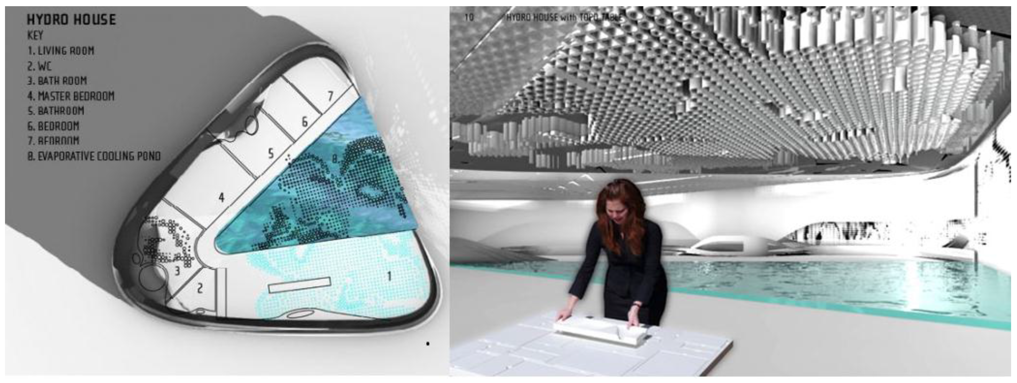
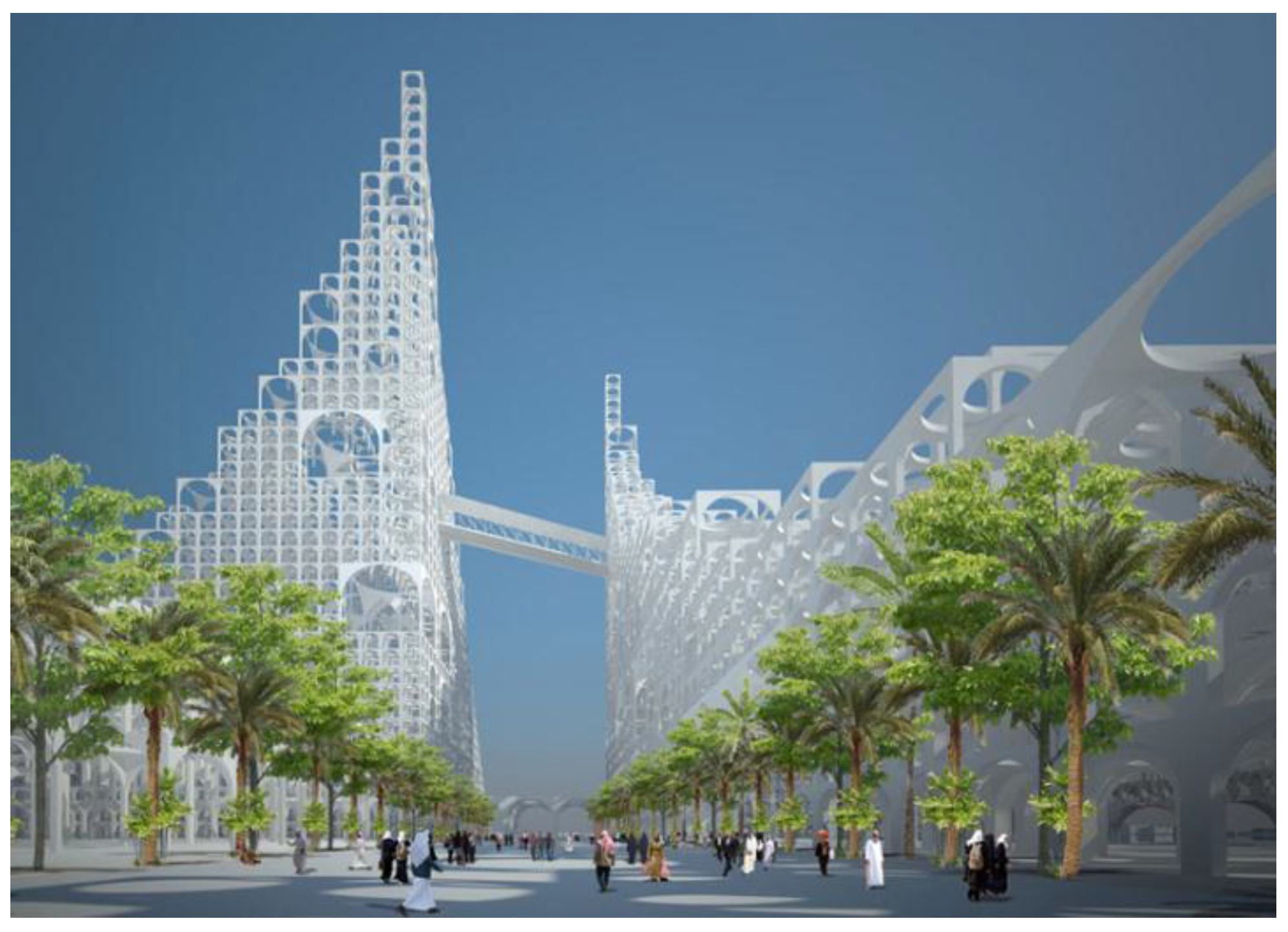
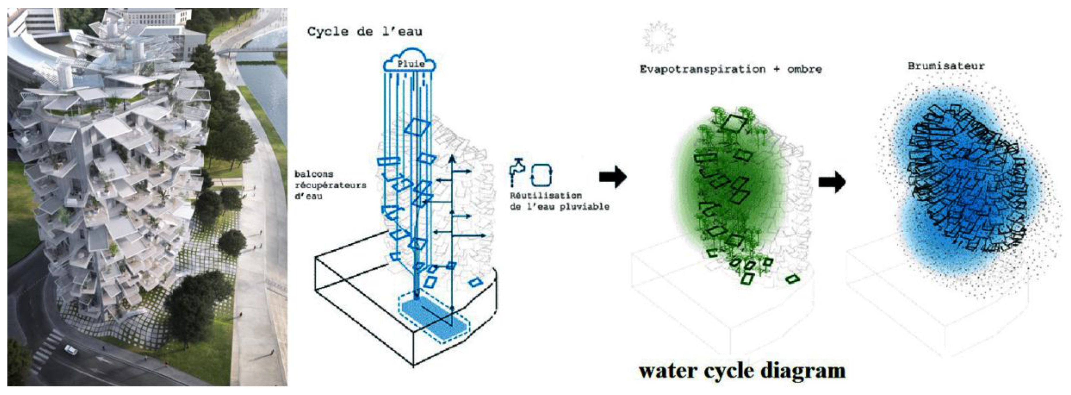
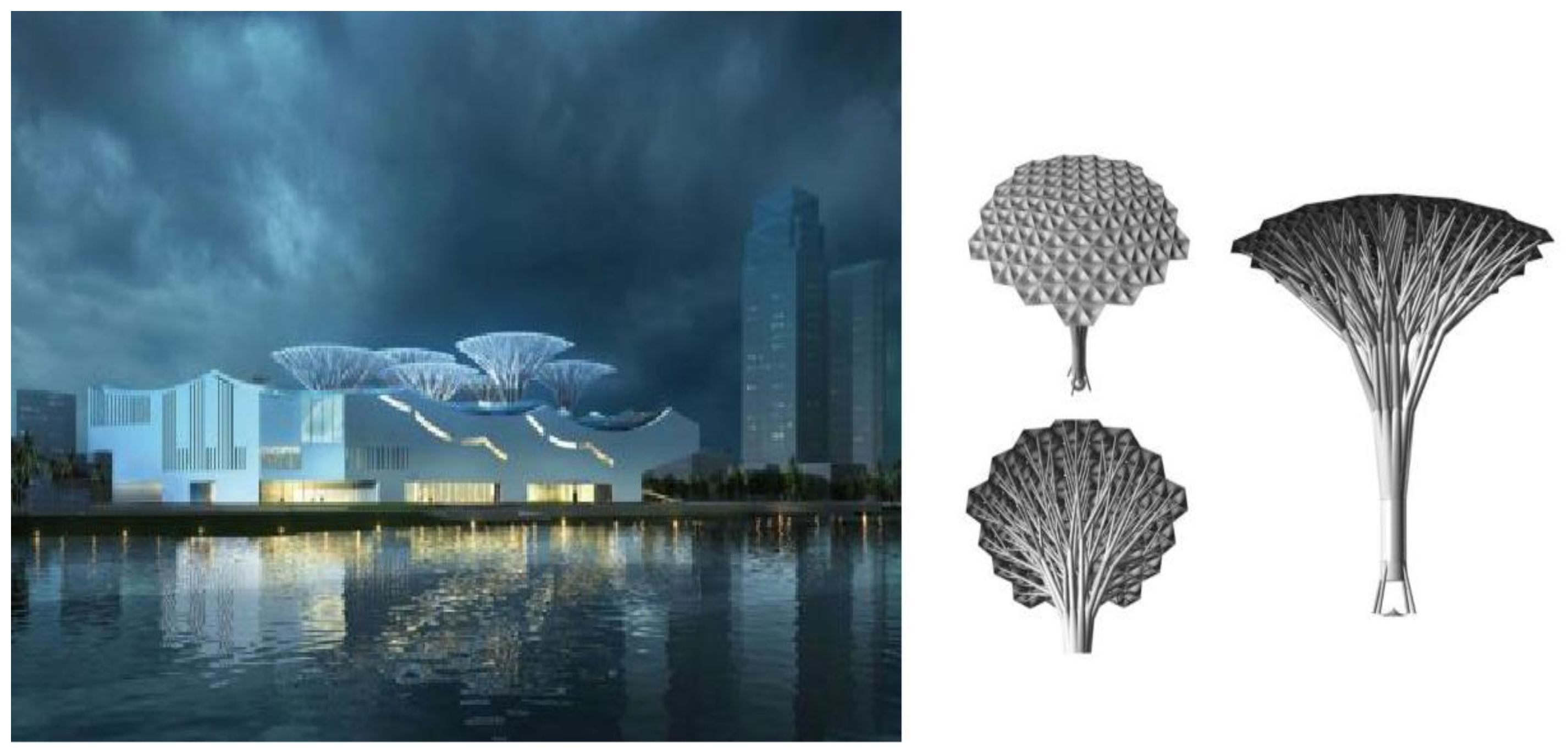
5. Ingenious Designs
6. Conclusions
Acknowledgments
Conflicts of Interest
References
- IEA. World Energy Outlook 2011 Factsheet; International Energy Agency: Paris, France, 2011. [Google Scholar]
- Masoso, O.T.; Grobler, L.J. The dark side of occupants’ behaviour on building energy use. Energy Build. 2010, 42, 173–177. [Google Scholar] [CrossRef]
- Chan, H.Y.; Riffat, S.B.; Zhu, J. Review of passive solar heating and cooling technologies. Renew. Sustain. Energy Rev. 2010, 14, 781–789. [Google Scholar] [CrossRef]
- Givoni, B. Passive Low Energy Cooling of Buildings; John Wiley & Sons: New York, NY, USA, 1994. [Google Scholar]
- Erell, E. Evaporative Cooling; Earthscan: London, UK, 2007; pp. 228–261. [Google Scholar]
- Costelloe, B.; Finn, D. Thermal effectiveness characteristics of low approach indirect evaporative cooling systems in buildings. Energy Build. 2007, 39, 1235–1243. [Google Scholar] [CrossRef]
- Shukla, A.; Tiwari, G.N.; Sodha, M.S. Experimental study of effect of an inner thermal curtain in evaporative cooling system of a cascade greenhouse. Solar Energy 2008, 82, 61–72. [Google Scholar] [CrossRef]
- Heidarinejad, G.; Moshari, S. Novel modeling of an indirect evaporative cooling system with cross-flow configuration. Energy Build. 2015, 92, 351–362. [Google Scholar] [CrossRef]
- Cerci, Y. A new ideal evaporative freezing cycle. Int. J. Heat Mass Transf. 2003, 46, 2967–2974. [Google Scholar] [CrossRef]
- Handbook, A. Evaporative Cooling Applications, HVAC Applications; American Society of Heating, Refrigerating and Air-Conditioning Engineers: N.E. Atlanta, GA, USA, 2003. [Google Scholar]
- La Roche, P.M. Carbon-Neutral Architectural Design; CRC Press: Boca Raton, FL, USA, 2011. [Google Scholar]
- Sharifi, A.; Yamagata, Y. Roof ponds as passive heating and cooling systems: A systematic review. Appl. Energy 2015, 160, 336–357. [Google Scholar] [CrossRef]
- Velasco Gómez, E.; Rey Martínez, F.J.; Varela Diez, F.; Molina Leyva, M.J.; Herrero Martín, R. Description and experimental results of a semi-indirect ceramic evaporative cooler. Int. J. Refrig. 2005, 28, 654–662. [Google Scholar] [CrossRef]
- Porumb, B.; Ungureşan, P.; Tutunaru, L.F.; Şerban, A.; Bălan, M. A Review of Indirect Evaporative Cooling Technology. Energy Procedia 2016, 85, 461–471. [Google Scholar] [CrossRef]
- Duan, Z.; Zhan, C.; Zhang, X.; Mustafa, M.; Zhao, X.; Alimohammadisagvand, B.; Hasan, A. Indirect evaporative cooling: Past, present and future potentials. Renew. Sustain. Energy Rev. 2012, 16, 6823–6850. [Google Scholar] [CrossRef]
- Maheshwari, G.; Al-Ragom, F.; Suri, R. Energy-saving potential of an indirect evaporative cooler. Appl. Energy 2001, 69, 69–76. [Google Scholar] [CrossRef]
- Jaber, S.; Ajib, S. Evaporative cooling as an efficient system in Mediterranean region. Appl. Therm. Eng. 2011, 31, 2590–2596. [Google Scholar] [CrossRef]
- Delfani, S.; Esmaeelian, J.; Pasdarshahri, H.; Karami, M. Energy saving potential of an indirect evaporative cooler as a pre-cooling unit for mechanical cooling systems in Iran. Energy Build. 2010, 42, 2169–2176. [Google Scholar] [CrossRef]
- Shapiro, L.E. Advanced Energy Saving Through the Use of Evaporative Cooling and Energy Recovery in Hybrid HVAC Systems; DTIC Document: Los Angeles, CA, USA, 2004. [Google Scholar]
- Crum, D. Open Cycle Airconditioning Systems. Master’s Thesis, Wisconsin-Madison, Madison, WI, USA, 1986. [Google Scholar]
- Rusten, E. Understanding Evaporative Cooling; Volunteers in Technical Assistance (VITA): Arlington, VA, USA, 1985. [Google Scholar]
- Ibrahim, E.; Shao, L.; Riffat, S.B. Performance of porous ceramic evaporators for building cooling application. Energy Build. 2003, 35, 941–949. [Google Scholar] [CrossRef]
- He, J.; Hoyano, A. A 3D CAD-based simulation tool for prediction and evaluation of the thermal improvement effect of passive cooling walls in the developed urban locations. Solar Energy 2009, 83, 1064–1075. [Google Scholar] [CrossRef]
- Jain, D.; Tiwari, G.N. Modeling and optimal design of evaporative cooling system in controlled environment greenhouse. Energy Convers. Manag. 2002, 43, 2235–2250. [Google Scholar] [CrossRef]
- Ghosal, M.K.; Tiwari, G.N.; Srivastava, N.S.L. Modeling and experimental validation of a greenhouse with evaporative cooling by moving water film over external shade cloth. Energy Build. 2003, 35, 843–850. [Google Scholar] [CrossRef]
- He, J.; Hoyano, A. A numerical simulation method for analyzing the thermal improvement effect of super-hydrophilic photocatalyst-coated building surfaces with water film on the urban/built environment. Energy Build. 2008, 40, 968–978. [Google Scholar] [CrossRef]
- Rafique, M.M.; Gandhidasan, P.; Rehman, S.; Al-Hadhrami, L.M. A review on desiccant based evaporative cooling systems. Renew. Sustain. Energy Rev. 2015, 45, 145–159. [Google Scholar] [CrossRef]
- Santamouris, M.; Kolokotsa, D. Passive cooling dissipation techniques for buildings and other structures: The state of the art. Energy Build. 2013, 57, 74–94. [Google Scholar] [CrossRef]
- Qiu, G.; Riffat, S. Novel design and modelling of an evaporative cooling system for buildings. Int. J. Energy Res. 2006, 30, 985–999. [Google Scholar] [CrossRef]
- Zhao, X.; Li, J.; Riffat, S. Numerical study of a novel counter-flow heat and mass exchanger for dew point evaporative cooling. Appl. Therm. Eng. 2008, 28, 1942–1951. [Google Scholar] [CrossRef]
- Zhao, X.; Liu, S.; Riffat, S. Comparative study of heat and mass exchanging materials for indirect evaporative cooling systems. Build. Environ. 2008, 43, 1902–1911. [Google Scholar] [CrossRef]
- Riangvilaikul, B.; Kumar, S. An experimental study of a novel dew point evaporative cooling system. Energy Build. 2010, 42, 637–644. [Google Scholar] [CrossRef]
- Riangvilaikul, B.; Kumar, S. Numerical study of a novel dew point evaporative cooling system. Energy Build. 2010, 42, 2241–2250. [Google Scholar] [CrossRef]
- Bruno, F. On-site experimental testing of a novel dew point evaporative cooler. Energy Build. 2011, 43, 3475–3483. [Google Scholar] [CrossRef]
- Camargo, J.R.; Ebinuma, C.D.; Silveira, J. Thermoeconomic analysis of an evaporative desiccant air conditioning system. Appl. Therm. Eng. 2003, 23, 1537–1549. [Google Scholar] [CrossRef]
- Eskra, N. Indirect-Direct Evaporative Cooling Systems. ASHRAE J. Am. Soc. Heat. Refrig. Air Cond. Eng. 1980, 22, 21–25. [Google Scholar]
- Kulkarni, R.; Rajput, S. Performance evaluation of two stage indirect/direct evaporative cooler with alternative shapes and cooling media in direct stage. Int. J. Appl. Eng. Res. 2010, 1, 800–812. [Google Scholar]
- Alonso, J.S.J.; Martinez, F.R.; Gomez, E.V.; Plasencia, M.A.-G. Simulation model of an indirect evaporative cooler. Energy Build. 1998, 29, 23–27. [Google Scholar] [CrossRef]
- Guo, X.; Zhao, T. A parametric study of an indirect evaporative air cooler. Int. Commun. Heat Mass Transf. 1998, 25, 217–226. [Google Scholar] [CrossRef]
- Zhan, C.; Duan, Z.; Zhao, X.; Smith, S.; Jin, H.; Riffat, S. Comparative study of the performance of the M-cycle counter-flow and cross-flow heat exchangers for indirect evaporative cooling–paving the path toward sustainable cooling of buildings. Energy 2011, 36, 6790–6805. [Google Scholar] [CrossRef]
- Heidarinejad, G.; Bozorgmehr, M.; Delfani, S.; Esmaeelian, J. Experimental investigation of two-stage indirect/direct evaporative cooling system in various climatic conditions. Build. Environ. 2009, 44, 2073–2079. [Google Scholar] [CrossRef]
- Heidarinejad, G.; Farmahini Farahani, M.; Delfani, S. Investigation of a hybrid system of nocturnal radiative cooling and direct evaporative cooling. Build. Environ. 2010, 45, 1521–1528. [Google Scholar] [CrossRef]
- Rick Phillips, P. Using direct evaporative+ chilled water cooling. ASHRAE J. Am. Soc. Heat. Refrig. Air Cond. Eng. 2009, 16–19. [Google Scholar]
- Bowman, N.; Eppel, H.; Lomas, K.; Robinson, D.; Cook, M. Passive downdraught evaporative cooling. Indoor Built Environ. 2001, 9, 284–290. [Google Scholar]
- Robinson, D.; Lomas, K.J.; Cook, M.J.; Eppel, H. Passive down-draught evaporative cooling: Thermal modelling of an office building. Indoor Built Environ. 2004, 13, 205–221. [Google Scholar] [CrossRef]
- Riffat, S.B.; Zhu, J. Mathematical model of indirect evaporative cooler using porous ceramic and heat pipe. Appl. Therm. Eng. 2004, 24, 457–470. [Google Scholar] [CrossRef]
- He, J.; Hoyano, A. Experimental study of cooling effects of a passive evaporative cooling wall constructed of porous ceramics with high water soaking-up ability. Build. Environ. 2010, 45, 461–472. [Google Scholar] [CrossRef]
- Liberty, J.T.; Ugwuishiwu, B.O.; Pukuma, S.A.; Odo, C.E. Principles and Application of Evaporative Cooling Systems for Fruits and Vegetables Preservation. Int. J. Curr. Eng. Technol. 2013, 3, 1000–1006. [Google Scholar]
- Ishizaki, K.; Komarneni, S.; Nanko, M. Porous Materials: Process Technology and Applications; Kluwer Academic: Dordrecht, The Netherlands, 1998. [Google Scholar]
- Chen, W.; Liu, S.; Lin, J. Analysis on the passive evaporative cooling wall constructed of porous ceramic pipes with water sucking ability. Energy Build. 2015, 86, 541–549. [Google Scholar] [CrossRef]
- Luyten, J.; Mullens, S.; Snijkers, F.; Buekenhoudt, A. Proceedings of the Global Roadmap for Ceramics-ICC2 Proceedings, Verona, Italy, 29 June–4 July 2008; pp. 309–316.
- Katsuki, H.; Furuta, S.; Shiraishi, A.; Komarneni, S. Porous mullite honeycomb by hydrothermal treatment of fired kaolin bodies in NaOH. J. Porous Mater. 1995, 2, 299–305. [Google Scholar] [CrossRef]
- Saito, Y.; Hayashi, S.; Yasumori, A.; Okada, K. Effects of calcining conditions of kaolinite on pore structures of mesoporous materials prepared by the selective leaching of calcined kaolinite. J. Porous Mater. 1996, 3, 233–239. [Google Scholar] [CrossRef]
- Katsuki, H.; Takagi, H.; Matsuda, O. Fabrication and properties of mullite ceramics with needle-like crystals. Ceram. Trans. 1992, 31, 137–146. [Google Scholar]
- Liu, Y.-F.; Liu, X.-Q.; Wei, H.; Meng, G.-Y. Porous mullite ceramics from national clay produced by gelcasting. Ceram. Int. 2001, 27, 1–7. [Google Scholar] [CrossRef]
- Okada, K.; Matsui, S.; Isobe, T.; Kameshima, Y.; Nakajima, A. Water-retention properties of porous ceramics prepared from mixtures of allophane and vermiculite for materials to counteract heat island effects. Ceram. Int. 2008, 34, 345–350. [Google Scholar] [CrossRef]
- Okada, K.; Kameshima, Y.; Nakajima, A.; Madhusoodana, C. Preparation of lotus-type porous ceramics with high water pump-up ability and its cooling effect by water vapor evaporation. J. Heat Island Inst. Int. 2007, 2, 1–5. [Google Scholar]
- Okada, K.; Uchiyama, S.; Isobe, T.; Kameshima, Y.; Nakajima, A.; Kurata, T. Capillary rise properties of porous mullite ceramics prepared by an extrusion method using organic fibers as the pore former. J. Eur. Ceram. Soc. 2009, 29, 2491–2497. [Google Scholar] [CrossRef]
- Takahashi, H.; Kobayashi, H.; Hinata, H. KAWAPROM ACE® pavement block manufactured by recycling fused sewage slag. Tech. Rep. Kawasaki 1995, 27, 19–26. [Google Scholar]
- Toya, T.; Tamura, Y.; Kameshima, Y.; Okada, K. Preparation and properties of CaO-MgO-Al2O3-SiO2 glass-ceramics from kaolin clay refining waste (Kira) and dolomite. Ceram. Int. 2004, 30, 983–989. [Google Scholar] [CrossRef]
- Washburn, E.W. The dynamics of capillary flow. Phys. Rev. 1921, 17, 273. [Google Scholar] [CrossRef]
- Isobe, T.; Kameshima, Y.; Nakajima, A.; Okada, K. Preparation and properties of porous alumina ceramics with uni-directionally oriented pores by extrusion method using a plastic substance as a pore former. J. Eur. Ceram. Soc. 2007, 27, 61–66. [Google Scholar] [CrossRef]
- Isobe, T.; Kameshima, Y.; Nakajima, A.; Okada, K.; Hotta, Y. Extrusion method using nylon 66 fibers for the preparation of porous alumina ceramics with oriented pores. J. Eur. Ceram. Soc. 2006, 26, 2213–2217. [Google Scholar] [CrossRef]
- Isobe, T.; Kameshima, Y.; Nakajima, A.; Okada, K.; Hotta, Y. Gas permeability and mechanical properties of porous alumina ceramics with unidirectionally aligned pores. J. Eur. Ceram. Soc. 2007, 27, 53–59. [Google Scholar] [CrossRef]
- Davidovits, J. Geopolymers. J. Therm. Anal. Calorim. 1991, 37, 1633–1656. [Google Scholar] [CrossRef]
- Duxson, P.; Fernández-Jiménez, A.; Provis, J.L.; Lukey, G.C.; Palomo, A.; Deventer, J.S.J. Geopolymer technology: The current state of the art. J. Mater. Sci. 2007, 42, 2917–2933. [Google Scholar] [CrossRef]
- Provis, J.L.; Lukey, G.C.; van Deventer, J.S.J. Do Geopolymers Actually Contain Nanocrystalline Zeolites? A Reexamination of Existing Results. Chem. Mater. 2005, 17, 3075–3085. [Google Scholar] [CrossRef]
- Shi, C.; Roy, D.; Krivenko, P. Alkali-Activated Cements and Concretes; CRC press: New York, NY, USA, 2006. [Google Scholar]
- Provis, J.L.; Van Deventer, J.S.J. Geopolymers: Structures, Processing, Properties and Industrial Applications; Elsevier: Amsterdam, The Netherlands, 2009. [Google Scholar]
- Pacheco-Torgal, F.; Labrincha, J.; Leonelli, C.; Palomo, A.; Chindaprasit, P. Handbook of Alkali-Activated Cements, Mortars and Concretes; Elsevier: Cambridge, UK, 2014. [Google Scholar]
- Duxson, P.; Provis, J.L.; Lukey, G.C.; van Deventer, J.S.J. The role of inorganic polymer technology in the development of ’green concrete’. Cem. Concr. Res. 2007, 37, 1590–1597. [Google Scholar] [CrossRef]
- Van Jaarsveld, J.G.S.; Van Deventer, J.S.J. Effect of metal contaminants on the formation and properties of waste-based geopolymers. Cem. Concr. Res. 1999, 29, 1189–1200. [Google Scholar] [CrossRef]
- He, J.; Zhang, J.; Yu, Y.; Zhang, G. The strength and microstructure of two geopolymers derived from metakaolin and red mud-fly ash admixture: A comparative study. Constr. Build. Mater. 2012, 80–91. [Google Scholar] [CrossRef]
- Davidovits, J. Geopolymers: man-made rock geosynthesis and the resulting development of very early high strength cement. J. Mater. Educ. 1994, 16, 91–139. [Google Scholar] [CrossRef]
- Examples of geopolymer frameworks. Available online: http://www.geopolymer.org/science/examples-geopolymer-frameworks (accessed on 20 August 2013).
- Verdolotti, L.; Iannace, S.; Lavorgna, M.; Lamanna, R. Geopolymerization reaction to consolidate incoherent pozzolanic soil. J. Mater. Sci. 2008, 43, 865–873. [Google Scholar] [CrossRef]
- Van Jaarsveld, J.G.S.; Van Deventer, J.S.J.; Lorenzen, L. The potential use of geopolymeric materials to immobilise toxic metals: Part I. Theory and applications. Minerals Eng. 1997, 10, 659–669. [Google Scholar] [CrossRef]
- Škvára, F.; Kopecký, L.; Nemecek, J.; Bittnar, Z. Microstructure of geopolymer materials based on fly ash. Silikáty 2006, 50, 208–215. [Google Scholar]
- Geopolymer/vermiculite composite. Available online: http://www.rmat.ceram.titech.ac.jp/research-e/heatiland-e.html (accessed on 3 July 2013).
- Poon, C.S.; Lam, L.; Kou, S.C.; Wong, Y.L.; Wong, R. Rate of pozzolanic reaction of metakaolin in high-performance cement pastes. Cem. Concr. Res. 2001, 31, 1301–1306. [Google Scholar] [CrossRef]
- Ding, J.T.; Li, Z. Effects of metakaolin and silica fume on properties of concrete. ACI Mater. J. 2002, 99, 393–398. [Google Scholar]
- Mustafa Al Bakri, A.M.; Kamarudin, H.; Bnhussain, M.; Khairul Nizar, I.; Rafiza, A.R.; Zarina, Y. Microstructure of different NaOH molarity of fly ash-based green polymeric cement. J. Eng. Technol. Res. 2011, 3, 44–49. [Google Scholar]
- Xie, J.; Yin, J.; Chen, J.; Xu, J. Study on the Geopolymer Based on Fly Ash and Slag. In Proceedings of the International Conference on Energy and Environment Technology, Guilin, China, 16–18 October 2009; pp. 578–581.
- Malhotra, V.M.; Mehta, P.K. Pozzolanic and Cementitious Materials; Taylor & Francis: Boca Raton, FL, USA, 1996; Volume 1. [Google Scholar]
- Van Deventer, J.S.J.; Provis, J.L.; Duxson, P. Technical and commercial progress in the adoption of geopolymer cement. Minerals Eng. 2012, 29, 89–104. [Google Scholar] [CrossRef]
- Lin, T.; Jia, D.; He, P.; Wang, M.; Liang, D. Effects of fiber length on mechanical properties and fracture behavior of short carbon fiber reinforced geopolymer matrix composites. Mater. Sci. Eng. A 2008, 497, 181–185. [Google Scholar] [CrossRef]
- He, P.; Jia, D.; Lin, T.; Wang, M.; Zhou, Y. Effects of high-temperature heat treatment on the mechanical properties of unidirectional carbon fiber reinforced geopolymer composites. Ceram. Int. 2010, 36, 1447–1453. [Google Scholar] [CrossRef]
- Xie, N.; Bell, J.L.; Kriven, W.M. Fabrication of Structural Leucite Glass–Ceramics from Potassium-Based Geopolymer Precursors. J. Am. Ceram. Soc. 2010, 93, 2644–2649. [Google Scholar] [CrossRef]
- Ge, Y.; Cui, X.; Kong, Y.; Li, Z.; He, Y.; Zhou, Q. Porous geopolymeric spheres for removal of Cu (II) from aqueous solution: Synthesis and evaluation. J. Hazard. Mater. 2015, 283, 244–251. [Google Scholar] [CrossRef] [PubMed]
- Dimas, D.D.; Giannopoulou, I.P.; Panias, D. Utilization of alumina red mud for synthesis of inorganic polymeric materials. Miner. Process. Extract. Metall. Rev. 2009, 30, 211–239. [Google Scholar] [CrossRef]
- Kumar, A.; Kumar, S. Development of paving blocks from synergistic use of red mud and fly ash using geopolymerization. Constr. Build. Mater. 2013, 38, 865–871. [Google Scholar] [CrossRef]
- Kusbiantoro, A.; Nuruddin, M.F.; Shafiq, N.; Qazi, S.A. The effect of microwave incinerated rice husk ash on the compressive and bond strength of fly ash based geopolymer concrete. Constr. Build. Mater. 2012, 36, 695–703. [Google Scholar] [CrossRef]
- de Sensale, G.R.; Ribeiro, A.B.; Gonçalves, A. Effects of RHA on autogenous shrinkage of Portland cement pastes. Cem. Concr. Compos. 2008, 30, 892–897. [Google Scholar] [CrossRef]
- Saraswathy, V.; Song, H.-W. Corrosion performance of rice husk ash blended concrete. Constr. Build. Mater. 2007, 21, 1779–1784. [Google Scholar] [CrossRef]
- Tangchirapat, W.; Buranasing, R.; Jaturapitakkul, C.; Chindaprasirt, P. Influence of rice husk–bark ash on mechanical properties of concrete containing high amount of recycled aggregates. Constr. Build. Mater. 2008, 22, 1812–1819. [Google Scholar] [CrossRef]
- Nazari, A.; Riahi, S.; Bagheri, A. Designing water resistant lightweight geopolymers produced from waste materials. Mater. Des. 2012, 35, 296–302. [Google Scholar] [CrossRef]
- Rattanasak, U.; Pankhet, K.; Chindaprasirt, P. Effect of chemical admixtures on properties of high-calcium fly ash geopolymer. Int. J. Min. Metall. Mater. 2011, 18, 364–369. [Google Scholar] [CrossRef]
- Sata, V.; Jaturapitakkul, C.; Rattanashotinunt, C. Compressive Strength and Heat Evolution of Concretes Containing Palm Oil Fuel Ash. J. Mater. Civ. Eng. 2010, 22, 1033–1038. [Google Scholar] [CrossRef]
- Chindaprasirt, P.; Homwuttiwong, S.; Jaturapitakkul, C. Strength and water permeability of concrete containing palm oil fuel ash and rice husk–bark ash. Constr. Build. Mater. 2007, 21, 1492–1499. [Google Scholar] [CrossRef]
- Nehdi, M. Ternary and quaternary cements for sustainable development. Concr. Int. 2001, 23, 35–42. [Google Scholar]
- Tippayasam, C.; Boonsalee, S.; Sajjavanich, S.; Ponzoni, C.; Kamseu, E.; Chaysuwan, D. Geopolymer development by powders of metakaolin and wastes in Thailand. Adv. Sci. Technol. 2011, 69, 63–68. [Google Scholar] [CrossRef]
- Hajiha, H.; Sain, M. 17–The use of sugarcane bagasse fibres as reinforcements in composites. In Biofiber Reinforcements in Composite Materials; Faruk, O., Sain, M., Eds.; Woodhead Publishing: Cambridge, UK, 2015; pp. 525–549. [Google Scholar]
- Alzeer, M.; MacKenzie, K.D. Synthesis and mechanical properties of new fibre-reinforced composites of inorganic polymers with natural wool fibres. J. Mater. Sci. 2012, 47, 6958–6965. [Google Scholar] [CrossRef]
- Dias, D.P.; Thaumaturgo, C. Fracture toughness of geopolymeric concretes reinforced with basalt fibers. Cem. Concr. Compos. 2005, 27, 49–54. [Google Scholar] [CrossRef]
- Bajare, D.; Bumanis, G.; Shakhmenko, G.; Justs, J. In Proceedings of the International Scientific Conference on Obtaining Composition of Geopolymers (Alkali Activated Binders) from Local Industrial Wastes, Civil Engineering, Jelgava, Latvia, 12–13 May 2011.
- Kang, D.; Strand, R.K.; Hammann, R.E.; Newell, T.A.; Vanka, P.S. Advances in the application of passive down-draft evaporative cooling technology in the cooling of buildings. Available online: http://hdl.handle.net/2142/26273 (accessed on 21 October 2015).
- Odesola, I.F.; Onyebuchi, O. A Review of Porous Evaporative Cooling for the Preservation of Fruits and Vegetables. Pac. J. Sci. Technol. 2009, 2, 935–941. [Google Scholar]
- Jain, D. Modeling of solar passive techniques for roof cooling in arid regions. Build. Environ. 2006, 41, 277–287. [Google Scholar] [CrossRef]
- Kamal, M.A. An Overview of Passive Cooling Techniques in Buildings: Design, Concepts and Architectural Interventions. Acta Tech. Napoc. Civil Eng. Archit. 2012, 55, 84–97. [Google Scholar]
- Ben Cheikh, H.; Bouchair, A. Passive cooling by evapo-reflective roof for hot dry climates. Renew. Energy 2004, 29, 1877–1886. [Google Scholar] [CrossRef]
- Naticchia, B.; D’Orazio, M.; Carbonari, A.; Persico, I. Energy performance evaluation of a novel evaporative cooling technique. Energy Build. 2010, 42, 1926–1938. [Google Scholar] [CrossRef]
- He, J. A design supporting simulation system for predicting and evaluating the cool microclimate creating effect of passive evaporative cooling walls. Build. Environ. 2011, 46, 584–596. [Google Scholar] [CrossRef]
- Hughes, B.R.; Calautit, J.K.; Ghani, S.A. The development of commercial wind towers for natural ventilation: A review. Appl. Energy 2012, 92, 606–627. [Google Scholar] [CrossRef]
- Ford, B.; Schiano-Phan, R.; Francis, E. The Architecture and Engineering of Downdraught Cooling: A Design Source Book; PHDC Press: Chicago, IL, USA, 2010. [Google Scholar]
- Bahadori, M.N. An improved design of wind towers for natural ventilation and passive cooling. Solar Energy 1985, 35, 119–129. [Google Scholar] [CrossRef]
- Schiano-Phan, R.; Ford, B. 324: Post Occupancy Evaluation of non-domestic buildings using owndraught cooling: Case studies in the US. In Proceedings of PLEA 2008–25th Conference on Passive and Low Energy Architecture, Dublin, Ireland, 22–24 October 2008.
- Kang, D.; Strand, R.K. Building Simulation. In Proceedings of the Building Simulation of Passive Down-Draught Evaporative Cooling (PDEC) Systems in EnergyPlus, Glasgow, Scotland, 27–30 July 2009.
- Pearlmutter, D.; Erell, E.; Etzion, Y.; Meir, I.; Di, H. Refining the use of evaporation in an experimental down-draft cool tower. Energy Build. 1996, 23, 191–197. [Google Scholar] [CrossRef]
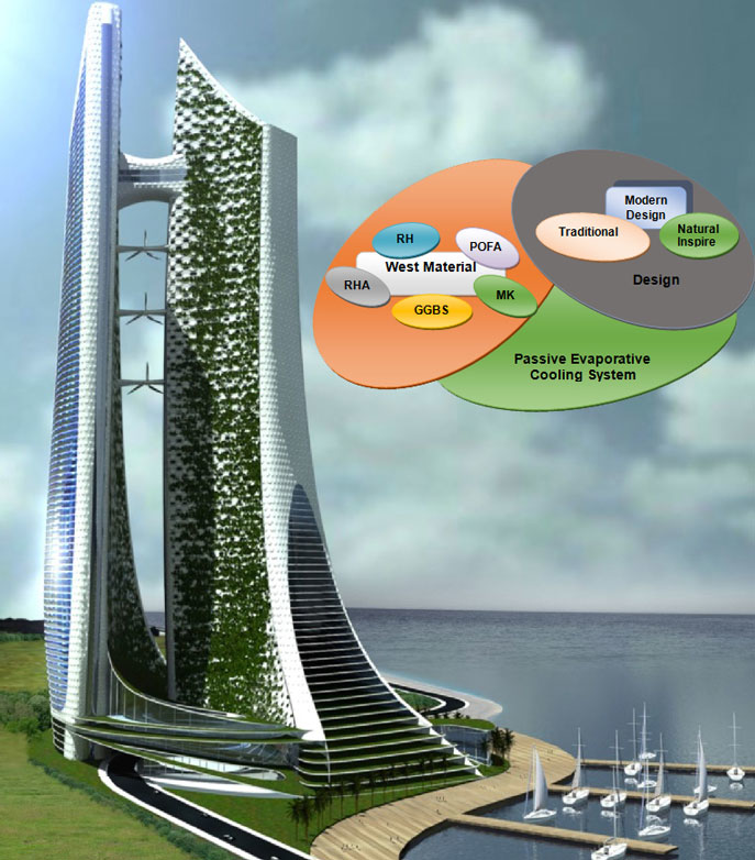
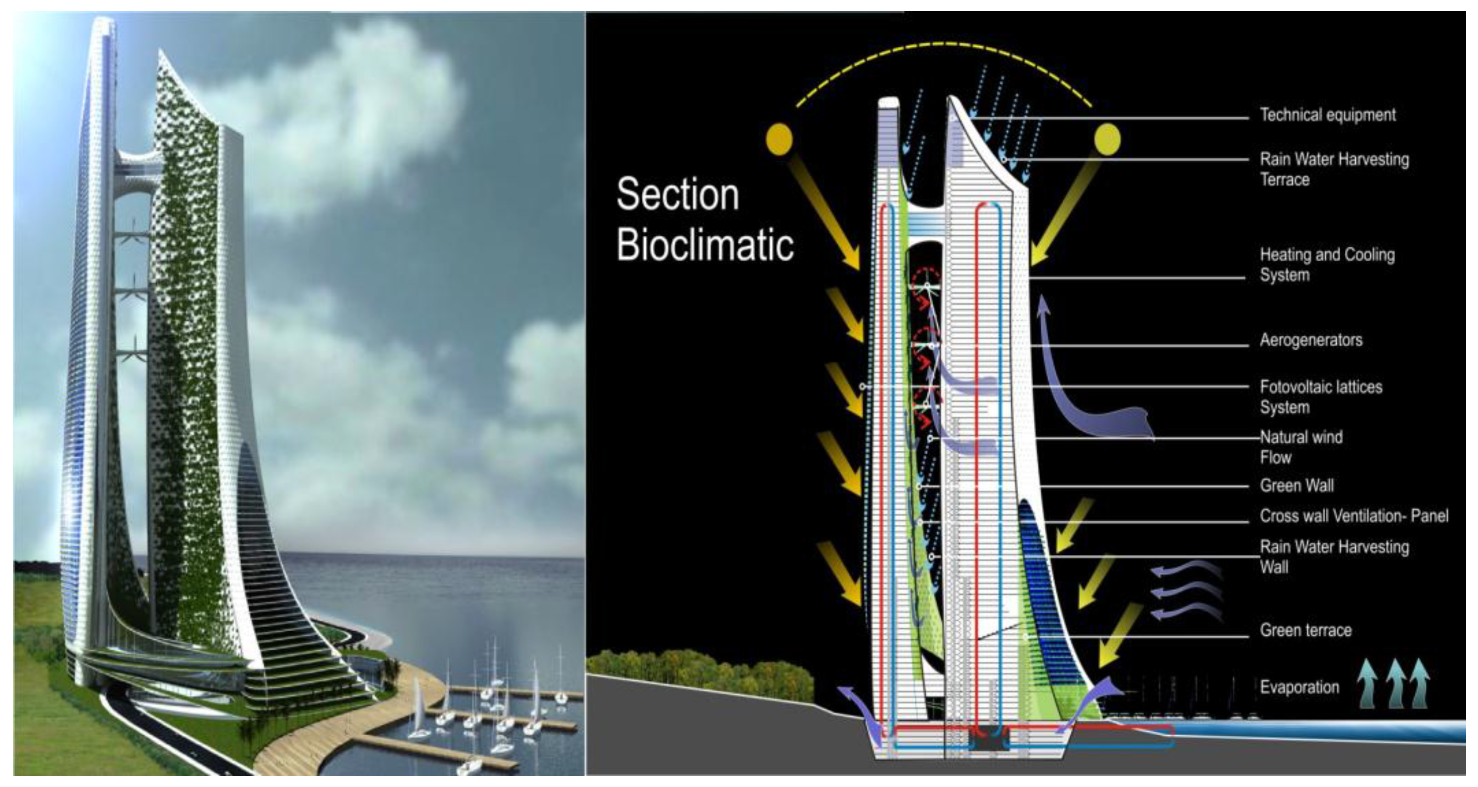
- Mineral Research and Tourist Hub, Badwater, CA. Available online: https://azizulhakimmusa.wordpress.com/2010/06/20/mineral-research-and-tourist-hub-badwater-ca/ (accessed on 10 August 2015).
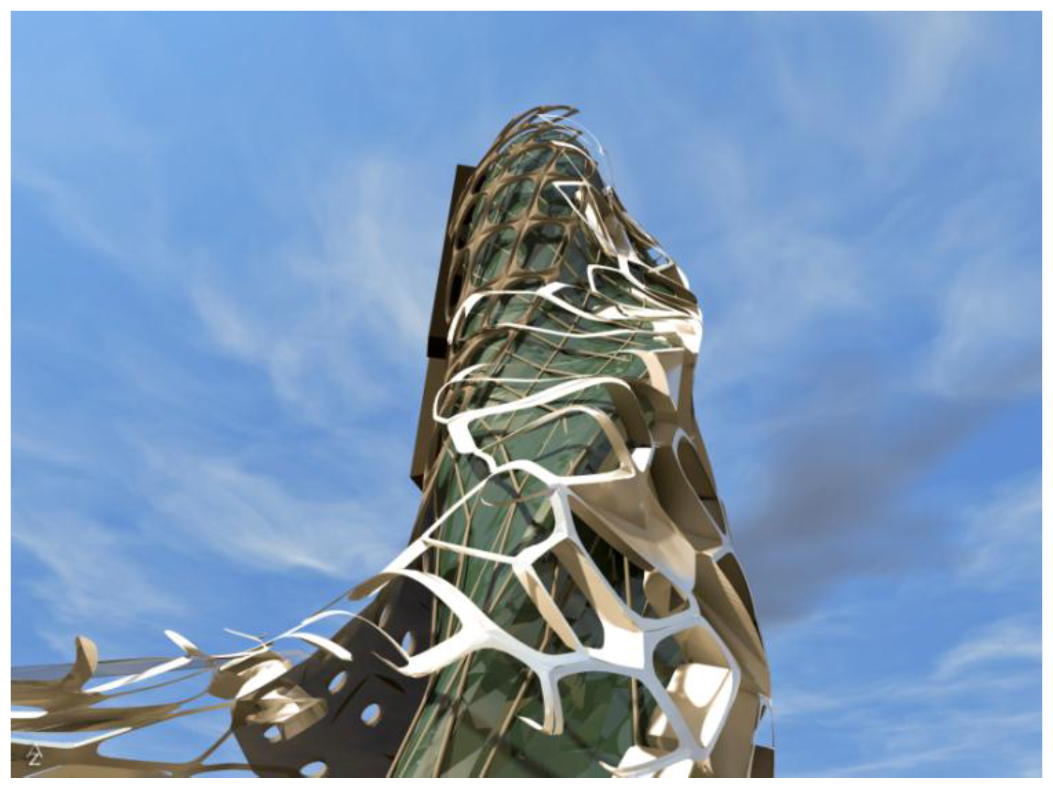
- Eco-Cybernetic City—Environmentally-Conscious Structure. Available online: http://www.infoniac.com/environment/eco-cybernetic-city-environmentally-conscious-structure.html (accessed on 27 July 2015).
- Hydro House concept. evolo-Architecture Magazine 2010. Available online: http://www.evolo.us/architecture/hydro-house-rael-san-fratello-architects/ (accessed on 3 July 2015).
- Sou Fujimoto designs nature-inspired towerfor Montpellier “modern follies” project. Available online: http://www.dezeen.com/2014/03/10/sou-fujimoto-montpellier-tower-modern-follies/ (accessed on 3 July 2015).
- Sou Fujimoto envisions trees and balconies for Université Paris-Saclay building. Available online: http://www.dezeen.com/tag/Sou-Fujimoto/ (accessed on 8 July 2015).
- Keeping Cool Through the Ages: Slideshow. Available online: http://www.dezeen.com/2013/11/20/sou-fujimoto-designs/ (accessed on 8 July 2015).
- Ábalos + Sentkiewicz arquitectos wins Zhuhai Huafa Contemporary Art Museum competition. Available online: http://aasarchitecture.com/2014/07/abalos-sentkiewicz-arquitectos-wins-zhuhai-huafa-contemporary-art-museum-competition.html (accessed on 1 July 2015).
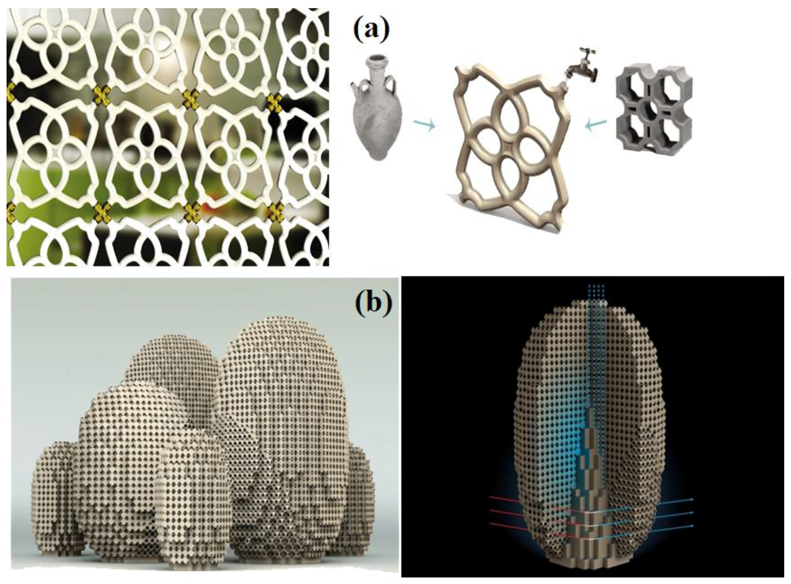
- Yoneda, Y. Ceramic “Ecooler” Screen is a Beautiful Passive Cooling System. Available online: http://inhabitat.com/ceramic-ecooler-screen-is-a-beautiful-passive-cooling-system/ (accessed on 1 July 2015).
- Art Installations Produce Microclimates. Evolo-Architecture Magazine 2010. Available online: http://www.evolo.us/architecture/art-installations-produce-microclimates-postlerferguson/ (accessed on 8 July 2015).


| Reference | System Description | Type of Model | Results |
|---|---|---|---|
| Qiu and Riffat [29] | Novel evaporative cooling system | Analytical | - |
| Zhao et al. [30] | Counter-flow indirect evaporative cooler (IEC) made from plate fin heat exchanger | Simulation | Wet bulb effectiveness (54%–130%) |
| Zhao et al. [31] | indirect evaporating cooler with five different materials as heat and mass transfer | Analytical | Dew point effectiveness (36%–82%) |
| Ringvilaikul and Kumar [32,33] | Counter-flow indirect evaporative cooler made from flat sheet, stacked structure heat exchanger | Experimental and simulation | Wet bulb effectiveness (92%–114%) |
| Bruno [34] | Counter-flow plate type exchanger based IEC | Experimental | Wet bulb effectiveness (106%–124%) |
| Camargo et al. [35] | Comparison of Direct evaporating cooling (DEC) and indirect evaporative cooling | Analytical | - |
| Eskra [36] | Two stage evaporative cooling | Simulation | Reduction of energy consumption (60%–75%) |
| Kulkarni and Rajput [ 37] | Two stage evaporative cooler | Analytical | Saturate efficiency (64%–89%) |
| Eskra [36] | Two stage evaporative cooler | Analytical | Wet bulb effectiveness (93%) |
| Alonso [38] | Cross-flow IEC made from plate fin heat exchanger | Simulation | Wet bulb effectiveness (77%–93%) |
| Guo [39] | IEC made from plate fin heat exchanger | Analytical | Wet bulb effectiveness (78%–95%) |
| Zhan [40] | Cross-flow IEC made from plate fin heat exchanger | Analytical | Wet bulb effectiveness (50%–65%) |
| Heidarnejad et al. [41] | Two stage DEC- IEC | Experimental | The effectiveness of the two stages is 108%–111% while the effectiveness of IEC is 55%–61%; 60% power saving. |
| Heidarnejad et al. [42] | Hybrid system including DEC coupled with of nocturnal radiative cooling, cooling coil | Experimental | The results demonstrate the overall effectiveness of hybrid system is more than 100%. |
| Phillips [43] | Chilled water coil conjunction with a DEC pad | Experimental | Using DEC in conjunction with a chilled coil results to 35% energy saving comparing the chilled coil for a LEED rated building, this corresponds to four credits for energy conservation. |
| Bowman et al. [44] and Robinson et al. [45] | Passive down draught evaporative cooling (PDEC) | Simulation | Saving between 50% and 83%, depending upon occupancy and set point. Thermal comfort could not be achieved by PDEC only. |
| Ibrahim et al. [22] | Porous ceramic evaporators (DEC) | Experimental Simulation Experimental | - |
| Riffat et al. [46] | |||
| He and Hoyano [47] |
© 2016 by the authors; licensee MDPI, Basel, Switzerland. This article is an open access article distributed under the terms and conditions of the Creative Commons Attribution (CC-BY) license (http://creativecommons.org/licenses/by/4.0/).
Share and Cite
Emdadi, Z.; Asim, N.; Ambar Yarmo, M.; Shamsudin, R.; Mohammad, M.; Sopian, K. Green Material Prospects for Passive Evaporative Cooling Systems: Geopolymers. Energies 2016, 9, 586. https://doi.org/10.3390/en9080586
Emdadi Z, Asim N, Ambar Yarmo M, Shamsudin R, Mohammad M, Sopian K. Green Material Prospects for Passive Evaporative Cooling Systems: Geopolymers. Energies. 2016; 9(8):586. https://doi.org/10.3390/en9080586
Chicago/Turabian StyleEmdadi, Zeynab, Nilofar Asim, Mohd Ambar Yarmo, Roslinda Shamsudin, Masita Mohammad, and Kamaruzaman Sopian. 2016. "Green Material Prospects for Passive Evaporative Cooling Systems: Geopolymers" Energies 9, no. 8: 586. https://doi.org/10.3390/en9080586