Article

Monitoring and Analysing Changes in Temperature and Energy in the Ground with Installed Horizontal Ground Heat Exchangers

Department of Mechanical Engineering, Faculty of Engineering, Czech University of Life Sciences Prague, Kamýcká 129, Prague-Suchdol 165 21, Czech Republic
*
Author to whom correspondence should be addressed.
Energies 2016, 9(8), 555; https://doi.org/10.3390/en9080555
Submission received: 10 May 2016 / Revised: 14 June 2016 / Accepted: 1 July 2016 / Published: 28 July 2016
(This article belongs to the Special Issue Advanced Heating and Cooling Techniques)

Abstract

:
The objective of this work was to monitor and analyse temperature changes in the ground with installed linear and Slinky-type horizontal ground heat exchangers (HGHEs), used as low-potential heat pump energy sources. Specific heat flows and specific energies extracted from the ground during the heating season were also measured and compared. The verification results showed that the average daily ground temperatures with the two HGHEs are primarily affected by the temperature of the ambient environment. The ground temperatures were higher than ambient temperature during most of the heating season, were only seldom below zero, and were higher by an average 1.97 ± 0.77 K in the ground with the linear HGHE than in the ground with the Slinky-type HGHE. Additionally, the specific thermal output extracted from the ground by the HGHE was higher by 8.45 ± 16.57 W/m2 with the linear system than with the Slinky system. The specific energies extracted from the ground over the whole heating season were 110.15 kWh/m2 and 57.85 kWh/m2 for the linear and Slinky-type HGHEs, respectively.

1. Introduction

According to the Intergovernmental Panel on Climate Change report [1], CO2 emissions should decrease by 40%–70% during the 2010–2050 period and global temperature increase should be limited by 2 °C compared to the level existing before the industrial revolution. The use of heat pumps for room heating and water heating may significantly help reach those ambitious targets. Statistical information of the U.S. Energy Information Administration, Residential Energy Consumption Survey (RECS) [2] shows that the share of energy use in residential and commercial buildings in total energy use in the country exceeds 22%. In this, about 65% energy is spent on room heating, residential house cooling, and hot water heating. Previous research [3] suggested that power systems with heat pumps consume 42%–62% less energy than the conventional heating/cooling systems. In contrast to other renewable sources (solar energy, wind energy), heat pumps transform energy directly between the low-potential energy source and the building without any need for additional heat transfer or accumulation.
Natural low-potential energy sources for heat pumps include air, surface water or groundwater, and ground or rock masses. According to the EHPA statistical report [4], the heat pumps predominating before 2006 were the ground-water type, whereas the air-water type started to predominate after that date. Currently, 61.07% of the installed heat pumps are the air-water type, 33.97% are the ground-water type, 2.84% are the water-water type, and 2.12% use other sources. The air-water pump type seems to owe its large-scale use to the lower investment costs and simple design. The energy savings and the operating costs, however, are not that beneficial.
In a reversed Carnot cooling cycle, the effect, which is expressed by the heating factor for a heat pump, is higher the smaller the temperature difference is between the cycle heat input and output. Assuming a constant condensation temperature, a higher heating factor can be attained via a higher evaporation temperature. The results of practical testing [5,6,7], as well as modelling [8], have shown that the ground temperatures are higher than the ambient temperatures during the major part of the heating season, whereas the reverse is true during the summer season. Hence, the ground is a convenient, stable, low-potential heat pump source for building heating in winter and for their cooling in summer.
The low-potential heat is extracted from/delivered to the rock/ground by means of vertical ground heat exchangers (VGHEs) or horizontal ground heat exchangers (HGHEs). VGHEs require a minimal land plot area, they work at a high efficiency, and are considered to be among the most stable low-potential energy sources; their installation, however, is very costly. HGHEs, existing in three design variants—linear, helical, or spiral [9], require a larger land area but are less costly. They are a compromise between a high efficiency and the investment costs. Petit and Meyer [10] examined the power and financial parameters of heat pumps using the following low-potential sources: air, HGHEs, and VGHEs. Air, as an energy source for heat pumps, emerged as the poorest of them. VGHEs provided the highest power output and HGHEs exhibited the most convenient heating factor and financial parameters. De Swart and Meyer [11] reported that at low ambient temperatures, the ground-water heat pump type provides a heating power and a heating factor 24% and 20%, respectively, higher than the air-water heat pump type.
Our measurements were aimed to:
  • Analyse temperature changes in the ground with a linear HGHE and a Slinky-type exchanger during the heating season;
  • Assess the effect of the HGHE configuration on the temperature values and distribution in the ground;
  • Assess the effect of the HGHE configuration on the specific heat flows and specific energies extracted from the ground.
The following hypotheses were tested:
(a)
The ground temperatures will be largely above zero during the heating season for both exchanger types. The ground temperatures in the exchanger area will be rarely below zero;
(b)
The temperatures of the ground with the linear HGHE will be higher than those with the Slinky-type exchanger;
(c)
The specific heat flows and specific energies extracted from the ground by the HGHE will be higher for the linear HGHE type than for the Slinky type.
The temperature distribution across the ground, the temperature gradients, and the heat flow densities shared between the ground surface and the surrounding environment were investigated by Popiel et al. [12]. Heat energy extraction from the ground, specific heat output of a linear HGHE and a Slinky-type HGHE, and the effect of the incident solar radiation on the ground energy balance were studied in detail by Wu et al. [13]. Garcia et al. [14] examined the interaction between the ground and an HGHE and found that heat extraction by the HGHE had a pronounced effect not only on the temperature, but also on the moisture, of the ground. The importance of knowledge of the ground temperature and of the climatic data of the ambient environment and their changes throughout the year, with respect to the HGHE configuration design, is stressed in the publication by Hepburn et al. [15], who examined the power and sustainability of HGHEs as low-potential energy sources for heat pumps depending on the ground temperatures and heat parameters. Extensive measurements resulted in a deeper insight into the effects of heat extraction by an HGHE and of the climatic conditions on the ground temperatures. Sanaye and Niroomand [16] engaged themselves in design optimisation and use of different configurations of linear HGHEs in relation to the ground temperature, extracted energy flows, and use of ground source heat pump (GSHP) systems, while Wu et al. [13] examined the design and operation of Slinky-type HGHEs with respect to similar parameters and conditions. Zarrella and De Carli [17] paid thorough attention to the impact of the interaction between the ground surface and environment on the performance of HGHE and on the effect of the heat pump. They created a model of thermal resistances and capacities respecting the state of the environment, solar radiation intensity, heat transfer via the radiation of the Earth’s surface to the sky, and the influence of the spacing of tubes of a spiral heat exchanger. They analysed the model in detail and verified it in operational mode. The simulation results showed good agreement with measurements and also showed an insignificant effect of the spacing of tubes of a spiral heat exchanger.
Requirements for the ground temperature with respect to the temperature of the HGHE’s heat-transfer fluid are set by the German VDI standard [18]. The effects of the ground moisture on the HGHE heat output and on the COP were investigated by Leong et al. [19]. Wu et al. [20] examined the temperatures of the ground with HGHEs used as low-potential energy sources for a conventional heat pump with a compressor and for an absorption type heat pump. The factors that affect the important thermal conductivity coefficient of the ground were analysed by Song et al. [21] and by Banks [22]. The effect of rainfall on the ground heat parameters and on the HGHE power was in the focus of Go et al. [23].

2. Materials and Methods

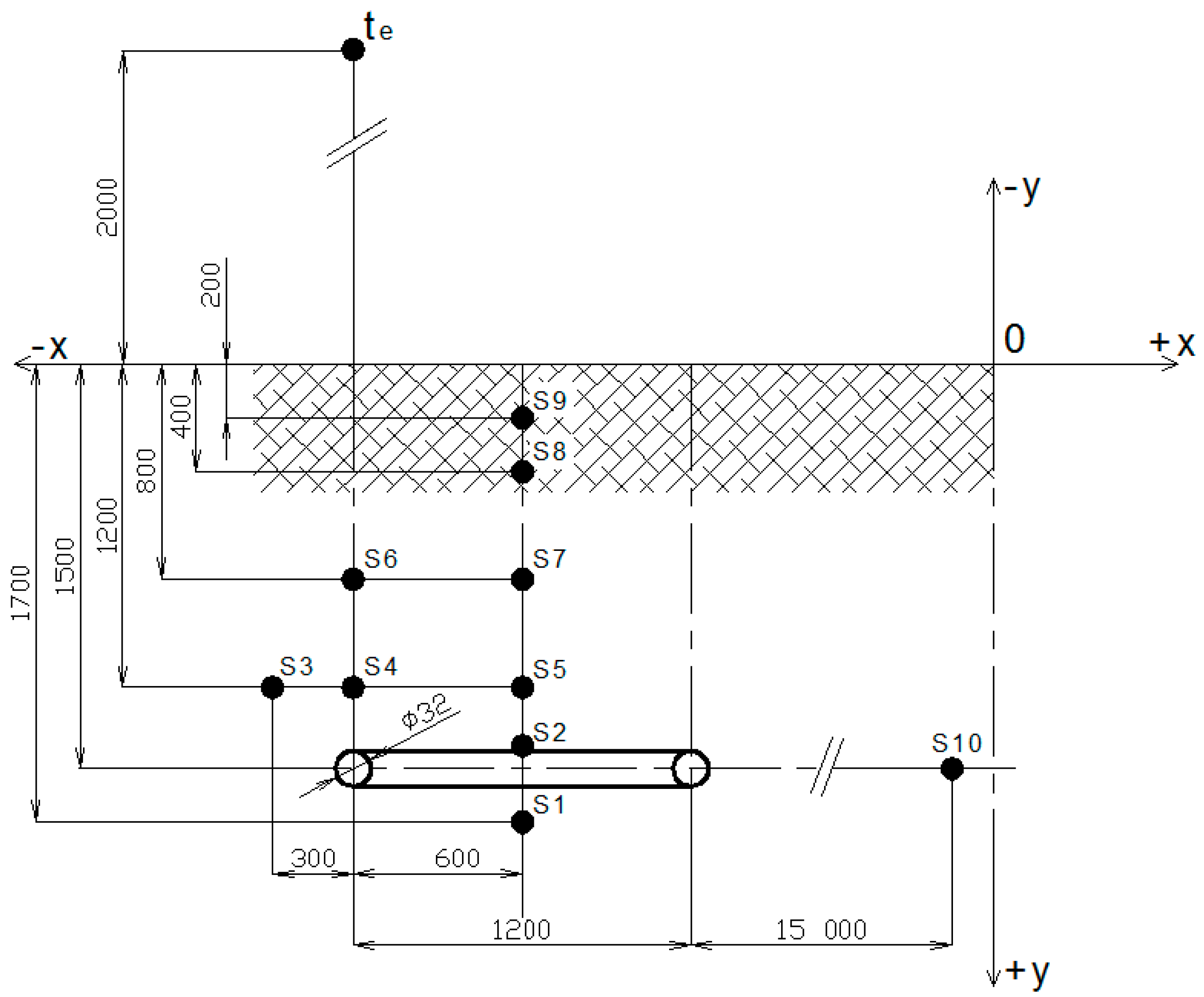
2.1. Measurement Methods

The linear horizontal ground heat exchanger was manufactured from polyethylene piping PE 100RC 40 mm × 3.7 mm (LUNA PLAST a. s., Hořín, Czech Republic), resistant to point loads and to the occurrence of cracks. The heat exchanger piping with the total length of 330 m (41.473 m2) was installed at a depth of 1.8 m in 3 loops at a 1 m span. The length of each loop was 54.62 m. Layouts of the HGHE and the locations of the temperature sensors are shown in Figure 1 and Figure 2.
The layouts of the Slinky-type HGHE and the sensor locations are shown in Figure 3 and Figure 4. The heat exchanger was manufactured from polyethylene piping PE 100RC 32 mm × 2.9 mm. It was not placed in a sand bed. The heat exchanger piping 200 m total length (20.107 m2) was installed at a depth of 1.5 m in 53 circular loops at a span of 0.38 m.
An ethyl alcohol/water 1:2 mixture served as the heat-transfer fluid for the two exchangers. The HGHEs used served as energy sources for IVT PremiumLine EQ E17 (Industriell Värme Teknik, Tnanas, Sweden) heat pumps, rated for 17 kW (0/35 °C) heat output. The heat pumps, along with three additional ones, are used for heating (not for cooling) of an administrative building and of the operational halls of VESKOM s.r.o. (=limited liability company) in Prague-Dolní Měcholupy (Czech Republic).
The ground temperatures were measured with GKF 125 and GKF 200 sensors and recorded every 30 minutes by means of ALMEMO 5990 and ALMEMO 2890-9 data acquisition systems. Ambient air temperatures te were measured 2 m above the ground, 20 m far from the horizontal ground exchangers, by using an ALMEMO FHA646AG sensor. An FLA613GS global radiation sensor was used to measure the incident solar radiation intensity. The total heat flow extracted by the horizontal exchangers was measured with MTW 3 (Itron Inc., Liberty Lake, WA, USA) electronic heat consumption meters.
The ground heat parameters—thermal conductivity coefficient λ (W/m·K), specific heat capacity C (MJ/m3·K) and temperature conductivity coefficient a (mm2/s)—at a temperature t (°C) and volumetric moisture w (%), measured with an ISOMET 2104 instrument (Applied Precision, Bratislava, Slovakia). Volumetric moisture of the ground was measured with soil moisture sensor SM 200 (Delta-T Devices Ltd, Burwell, Cambridge, UK).
The ground in which the HGHEs were installed was defined as Technosol [24]. The ground profile consisted of two layers: an arable land layer (approximately 0.25 m) and a layer of detritus (approximately 2 m) consisting of dark-brown sand-clay soil, coarse-grain gravel, crushed rock, and brick debris.
The measurements were performed from 17 September 2012 and covered one heating season.

2.2. Method to Determine the Development of the Average Daily Temperatures

The development of the rock mass’ average daily temperatures during the heating season can be described by Equation (1) which is based on the equation of free undamped oscillation of a mass point [6,25]:
t G R = t ¯ G + Δ t A × sin ( Ω . τ + ϕ )
where:
  • t G R = ground temperature (°C)
  • t ¯ G = mean ground temperature (°C)
  • Δ t A = oscillation amplitude around the temperature t ¯ G (K)
  • τ = number of days from the start of measurement (day)
  • ϕ = initial phase of oscillation (rad)
  • Ω = angular velocity (2π/365 rad/day)
This equation expresses nonlinear regression of y on x, and so the degree of tightness between the two parameters was characterized by the determination index I y x 2 (Bowerman et al. [26]). Equation (1) expresses only the course of the ground temperature in the HGHE area during the heating season. It does not aim to analyse the interaction between the ambient environment and the ground temperature in the HGHE area. However, it also includes the influence of climatic conditions on the ground.

3. Results and Discussion

3.1. Basic Ground Heat Parameters

The heat parameters were measured in the ground with a Slinky-type HGHE in June 2012, during the exchanger stagnation period. The results are listed in Table 1.

3.2. Ground Temperatures During the Heating Season

Table 2 summarizes the average daily temperatures of the ground with the linear HGHE and the parameters in Equation (1) for the heating season. The average daily temperatures during the heating season calculated from Equation (1) are plotted in Figure 5. The left vertical axis shows the temperatures tLR of the ground with linear HGHE. The right vertical axis te shows the ambient temperature.
Both the data in Table 2 and the plot in Figure 5 demonstrate that the average daily temperature of the ground with the linear HGHE decreases toward the ground surface. The lowest temperatures were not attained in the HGHE; instead, they were observed near the mass surface. The oscillation amplitude ΔtA around the mean ground temperature t ¯ G increases toward the ground surface. Both trends confirm an appreciable effect of ambient temperature te. Some effect of the linear HGHE on the ground temperature is indicated by the difference between the mean ground temperature t ¯ G near the HGHE and the mean reference temperature tL11, measured at a distance of 12.5 m from the HGHE centre, as well as by the difference between the oscillation amplitudes ΔtA in the ground with the HGHE and beyond it.
Table 3 and Figure 6 show the average daily ground temperatures during the heating season for the setting with the Slinky-type HGHE and appropriate parameters in Equation (1). The left vertical axis shows the temperature tSR of the ground with Slinky-type HGHE. The right vertical axis shows ambient temperature te.
The decreasing trend of the average daily ground temperature and the increasing trend of oscillation amplitude ΔtA around the mean ground temperature t ¯ G in the setting with the Slinky-type HGHE are similar to those in the setting with the linear HGHE, although the former HGHE extracts heat from an appreciably smaller volume than the latter. The smaller mass volume is mirrored in the lower mean daily temperatures.
The determination index values I y x 2 exhibit adequate precision of Equation (1), describing the ground temperature development during the heating season, for both HGHE types.
The decreasing trend of the average daily ground temperature and the increasing trend of oscillation amplitude ΔtA around the mean ground temperature t ¯ G in the setting with the Slinky-type HGHE are similar to those in the setting with the linear HGHE, although the former HGHE extracts heat from an appreciably smaller mass volume than the latter. The smaller mass volume is mirrored in the lower mean daily temperatures. The difference of the average daily ground temperature tL1tS1 during the heating season, at a distance of 0.2 m below HGHEs was Δt1 = 2.28 ± 1.13 K. The ground temperature differences decrease toward the surface of ground. The difference of the average daily temperatures at a depth of 0.2 m below the surface was Δt9 = tL9tS9 = 1.13 ± 0.71 K.
The determination index values I y x 2 exhibit adequate precision of Equation (1), describing the ground temperature development during the heating season, for both HGHE types.

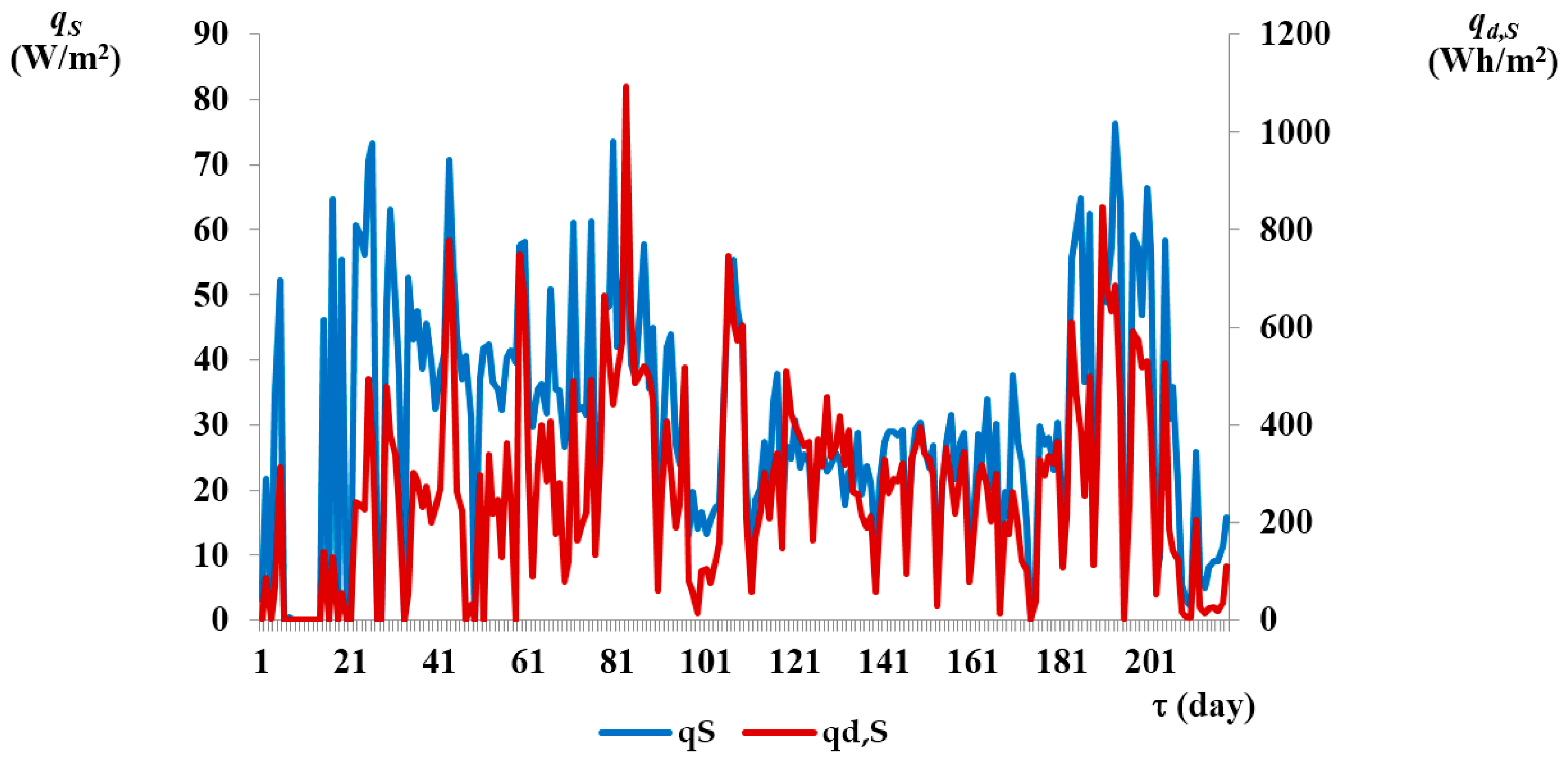
3.3. Heat Flows and Specific Energies Extracted from the Ground

Figure 7 displays plot of the ground temperatures tL2, tS2 in the HGHE area, the reference ground temperatures tL11, tS10 beyond the HGHE area, and ambient temperatures te during the heating season. Furthermore, the plots in Figure 8 and Figure 9 include the thermal output values q,S, q,L and specific energies qd,S qd,L per m2 of the HGHEs’ external heat exchange area, and also the intensity Is.r and energy Id,s.r. of the incident solar radiation during a day per m2. Specific thermal outputs qL, qS were determined based on the measured volume flow of heat transfer fluid, specific heat capacity and heat transfer fluid temperature difference at the inlet and outlet of the evaporator heat pump. Specific energies qd,L, qd,S extracted from the ground were determined based on the specific thermal output and heat pump operation time at a certain power output. The results are summarised in Table 4.
The plots in Figure 7 and the summary data in Table 2 show that the average daily ground temperatures near the HGHEs were below zero. Minimum ground temperatures in the HGHE area were reached almost on the same days of the heating season. The minimum average daily temperature was tL2 = 2.00 °C (190 days) and tS2 = −0.19 °C (192 days) with linear HGHE and the Slinky-type HGHE, respectively. The temperatures were decreasing on average 1 K per 12.55 days and per 11.36 days with linear HGHE and Slinky-type HGHE, respectively. Due to the increasing ambient temperature at the end of the heating period, the average daily ground temperature in the HGHE area was also increasing. The ground temperatures tL2, tS2 in the HGHE area at the end of the heating period differed by only 0.64 K and reached approximately 31.5% of the ground temperatures at the beginning of the heating season.
The average daily ground temperatures in the HGHE area were 1.97 ± 0.77 K higher for the linear HGHE than for the Slinky-type HGHE, while the total specific energy extracted from the HGHE during the heating season was nearly twice as high for the linear HGHE than for the Slinky-type HGHE. The ground temperatures in the HGHE area during the heating season were 68.8% (linear HGHE) and 53.6% (Slinky-type HGHE) higher than the ambient temperature te. VGHEs with a single U-tube exchanger (2 mm × 40 mm × 3.7 mm) and with a double U-tube exchanger (4 mm × 32 mm × 2.9 mm) were also examined at the same site, at the same ambient temperatures, and at the same heat-transfer fluid concentration. The average rock mass temperatures were lower for either of the VGHEs than for the linear HGHE. The rock mass temperatures in the VGHE area were higher than the ambient temperatures te only during 59.72% (single U exchanger) and 62.96% (double U exchanger) of the heating season.
The reference daily rock mass temperature tL11 measured 12.5 m from the centre of the linear HGHE heat exchange area was higher by an average 2.22 ± 1.23 K than the temperature tL2 within the linear HGHE area. The temperature tS10 measured 15.6 m from the centre of the Slinky-type HGHE heat exchange area was higher by an average 3.05 ± 1.41 K, compared to temperature tS2.
The specific energies qd extracted during a day of the heating season were 239.91 ± 198.35 Wh/m2·day in average higher with the linear HGHE than with the Slinky-type HGHE. The specific energies extracted from the ground over the entire heating season were 110.15 kWh/m2 (linear HGHE) and 57.85 kWh/m2 (Slinky-type HGHE). Additionally, the average specific thermal outputs qL extracted from the ground by the linear HGHE were higher by 8.45 ± 16.57 W/m2 than qS extracted by the Slinky-type HGHE.
The better results obtained with the linear HGHE are presumably due to the larger mass volume from which the low-potential energy was extracted.
The importance of solar radiation for the ground energy potential can be documented by the total solar radiation energy hitting the ground surface during the heating season, which is IΣd,s.r. = 350 kWh/m2.

4. Conclusions

The operational testing of the HGHEs provided a deeper insight into the processes, usable in practical design and manufacturing work and, at the same time, inspiring future research trends in this field.
The monitoring and evaluation of the ground temperature changes during the heating season have shown that:
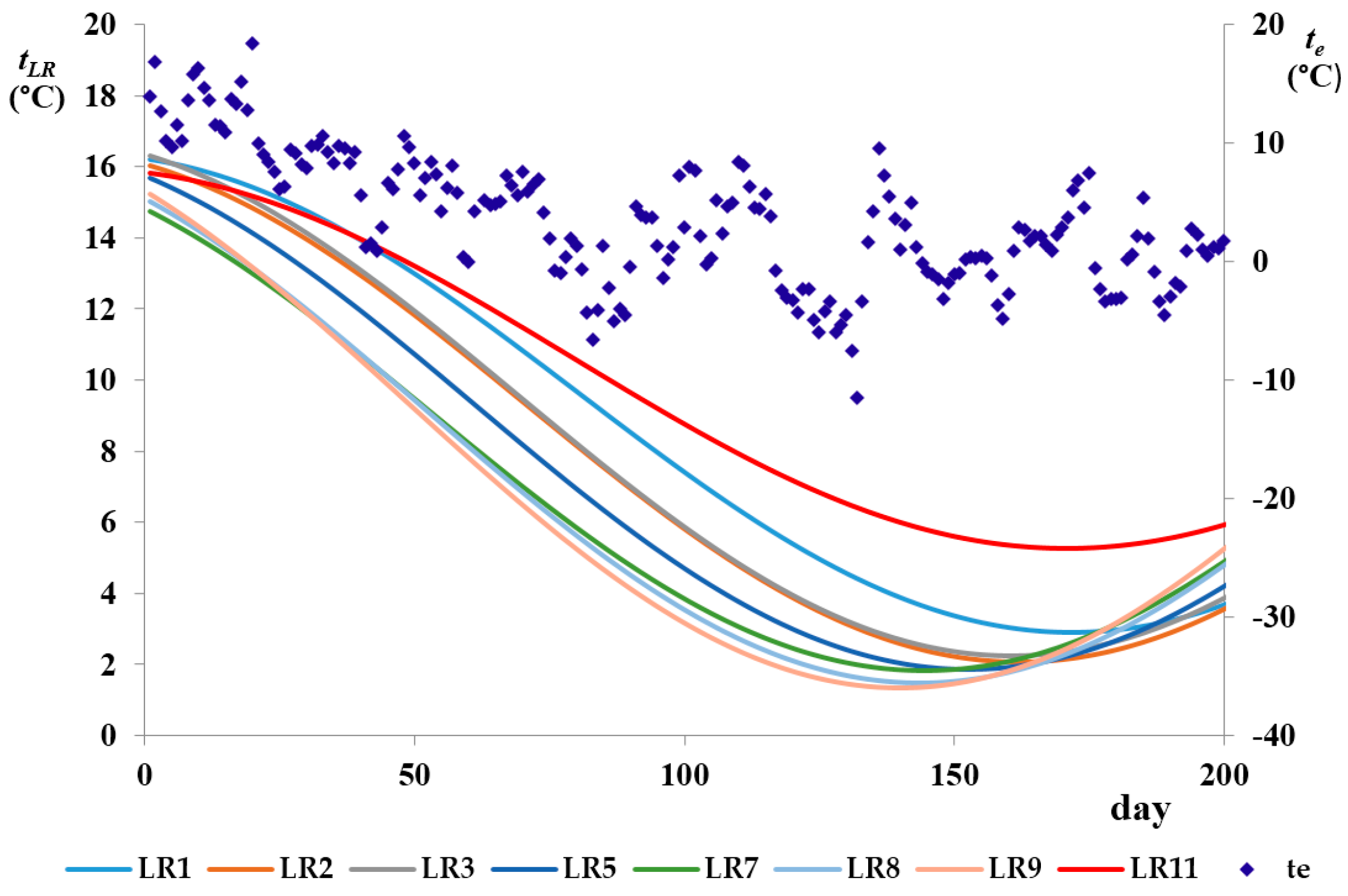
  • The average daily ground temperature was primarily influenced by the ambient temperature te irrespective of the HGHE type. The average daily ground temperatures above the HGHEs during the heating season decreased toward the ground surface. Ground sensitivity to short-time ambient temperature changes has been noticed by Hepburn et al. [15], Popiel et al. [12], Inalli, Esen [5], and Zarrella and De Carli [17];
  • The ground temperature near the HGHE was higher than ambient temperature te during 68.8% (linear HGHE) and 53.6% (Slinky-type HGHE) of the heating season. Ambient temperature was higher than the ground temperature particularly towards the end of the heating season. The importance of higher temperatures of a low-potential source for a heat pump has been pointed to by De Swardt, Meyer [11], as well as by Hepburn et al. [15];
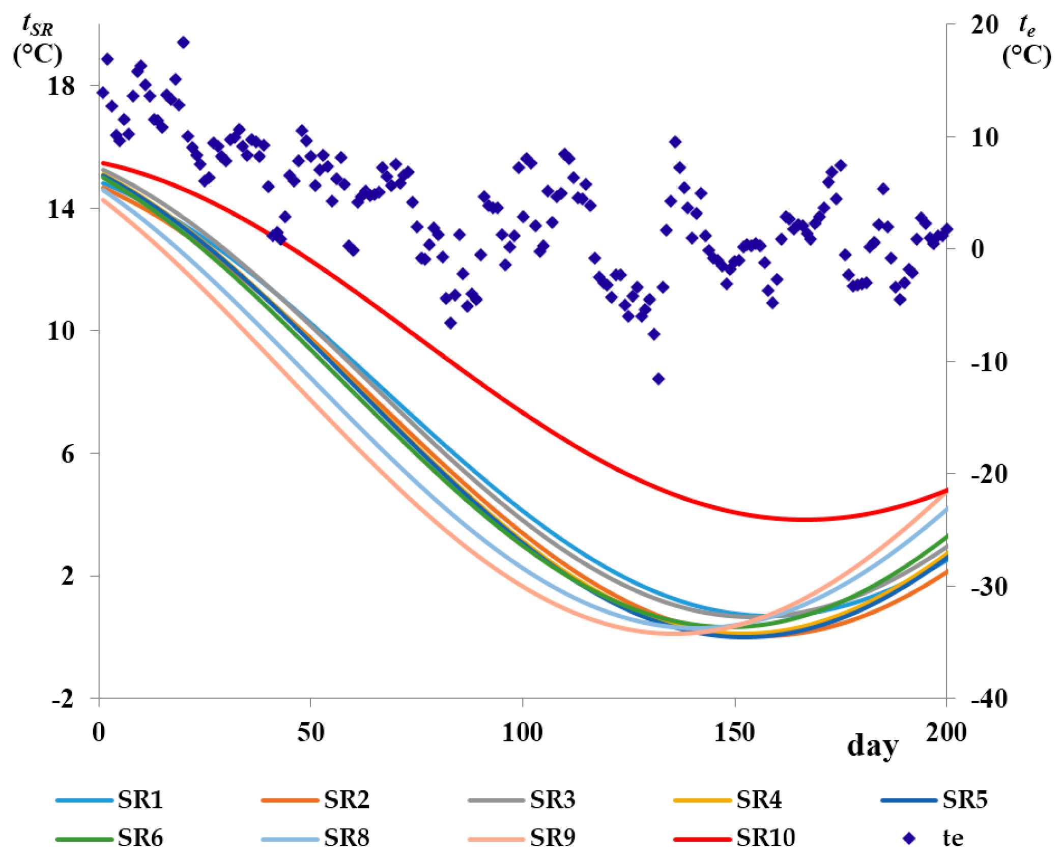
  • The average daily ground temperatures within the HGHE area were below zero only in the setting with the Slinky-type HGHE, and this was particularly toward the end of the heating season. Hypothesis a) formulated at the beginning of this paper was thereby confirmed;
  • The average daily ground temperature within the HGHE area was 1.97 ± 0.77 K higher in the setting with the linear HGHE than in the setting with the Slinky-type HGHE. The minimum daily ground temperatures were also higher in the former setting than in the latter setting. Hypothesis b) was thereby confirmed;
  • The reference average daily ground temperature beyond the HGHE area during the heating season was only 2.22 ± 1.23 K (linear HGHE) and 3.05 ± 1.41 K (Slinky-type HGHE) higher than that within the HGHE area. The differences between the reference ground temperatures and the temperatures within the HGHE areas are in accordance with the VDI recommendations [18];
  • The average daily ground temperatures with the HGHEs during the heating season can be described by Equation (1) and by the parameters listed in Table 2 and Table 3.
Measurements of the specific heat flows and the specific energies extracted from the ground during the heating season have shown that:
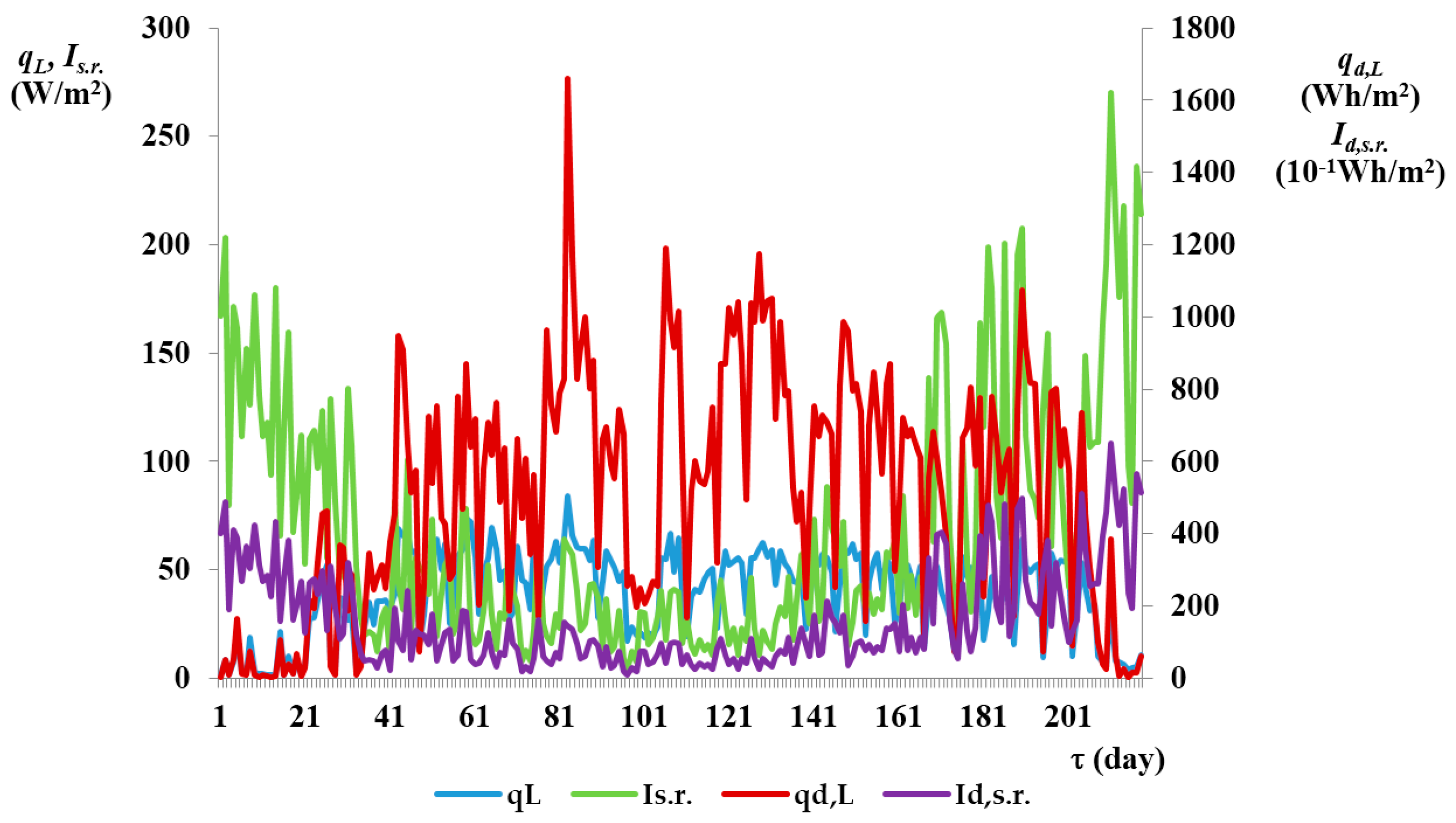
  • The specific energies extracted from the ground during a day of the heating season qd were higher by an average 239.91 ± 198.35 Wh/(m2·day) in the setting with the linear HGHE than in the setting with the Slinky-type HGHE. The specific energies extracted from the ground during the entire heating season were 110.15 kWh/m2 for the linear HGHE and 57.85 kWh/m2 for the Slinky-type HGHE. Hypothesis c) was thereby confirmed;
  • The average specific thermal outputs qL extracted from the ground by the HGHE were 8.45 ± 16.57 W/m2 higher in the setting with the linear HGHE than in the setting with the Slinky-type HGHE. Hypothesis c) was thereby confirmed. Similar thermal output levels were reported by Wu et al. [20];
  • Incident solar radiation plays an important role in the ground energy potential. The average incident solar radiation intensity during the heating season was Is.r. = 66.27 ± 55.35 W/m2. The total energies of solar radiation hitting the ground surface during the heating season were IΣd,s.r. = 350 kWh/m2. The data obtained by Hepburn et al. [15] and Wu et al. [19] were similar.
The measurements gave evidence that, with respect to the ground temperatures and energies extracted, the linear HGHE, as a low-potential energy source for heat pumps, is more convenient than the Slinky-type HGHE. On the other hand, the former design requires a larger land area for its operation than the latter design.
Our forthcoming work will be aimed to optimise the HGHE configuration and GSHP operation with focus on a reduction of the land area required for energy extraction from the ground.

Author Contributions

All authors contribute equally to this paper.

Conflicts of Interest

The authors declare no conflict of interest.

Nomenclature

Abbreviations 

HGHE
Horizontal Ground Heat Exchanger
VGHE
Vertical Ground Heat Exchanger
GSHP
Ground Source Heat Pump
COP
coefficient of performance
EHPA
European Heat Pump Association
λ
thermal conductivity coefficient (/W/m·K)
C
specific heat capacity (MJ/m3·K)
a
temperature conductivity coefficient (m2/s)
t
temperature (°C)
t ¯
mean temperature (°C)
w
volumetric moisture (%)
ΔtA
oscillation amplitude around the temperature t ¯ (K)
τ
number of days from the start of measurement (day)
ϕ
initial phase of oscillation (rad)
Ω
angular velocity (2·π/365 rad/day)
I y x 2
determination index (-)
Is.r.
solar radiation intensity (W/m2)
q
specific thermal output (W/m2)
qd
specific energy (Wh/m2)

Substript 

L
linear HGHE
S
Slinky-type HGHE
e
ambient air
G
ground
R
regression function
d
day

References

  1. IPCC. Summary for Policy Makers, Climate Change 2014, Mitigation of Climate Change (2014). Available online: http://www.ipcc.ch/pdf/assessment-report/ar5/wg3/ipcc_wg3_ar5_summary-for-policymakers.pdf (accessed on 16 April 2016).
  2. Residential Energy Consumption Survey (2014) EIA. Available online: http://www.eia.gov/consumption/residential/ (accessed on 5 October 2015).
  3. Aste, N.; Adhikari, R.S.; Manfren, M. Cost optimal analysis of heat pump technology adoption in residential reference buildings. Renew. Energy 2013, 60, 615–624. [Google Scholar] [CrossRef]
  4. Nowak, T.; Jaganjacova, S. European Heat Pump Market and Statistics Report 2013, 1st ed.; European Heat Pump Association: Brussels, Belgium, 2014; p. 197. [Google Scholar]
  5. Inalli, M.; Esen, H. Experimental thermal performance evaluation of a horizontal ground-source heat pump systém. Appl. Therm. Eng. 2004, 24, 2219–2232. [Google Scholar] [CrossRef]
  6. Neuberger, P.; Adamovsky, R.; Seďova, M. Temperatures and Heat Flows in a Soil Enclosing a Slinky Horizontal Heat Exchanger. Energies 2014, 7, 972–978. [Google Scholar] [CrossRef]
  7. Adamovsky, D.; Neuberger, P.; Adamovsky, R. Changes in energy and temperature in the ground mass with horizontal heat exchangers—The energy source for heat pumps. Energy Build. 2015, 92, 107–115. [Google Scholar] [CrossRef]
  8. Kupiec, K.; Larwa, B.; Gwadera, M. Heat transfer in horizontal ground heat exchangers. Appl. Therm. Eng. 2015, 75, 270–276. [Google Scholar] [CrossRef]
  9. Brandl, H. Energy foundations and other therma-active ground structures. Géotechnique 2006, 56, 81–122. [Google Scholar] [CrossRef]
  10. Petit, P.J.; Meyer, J.P. Techno-economic analysis between the performances of heat source air conditioners in South Africa. Energy Convers. Manag. 1998, 39, 661–669. [Google Scholar] [CrossRef]
  11. De Swardt, C.A.; Meyer, J.P. A performance comparison between an air-coupled and a ground-coupled reversible heat pump. Int. J. Energy Res. 2001, 25, 810–899. [Google Scholar] [CrossRef]
  12. Popiel, C.; Wojtkowiak, J.; Biernacka, B. Measurements of temperature distribution in ground. Exp. Therm. Fluid Sci. 2001, 25, 301–309. [Google Scholar] [CrossRef]
  13. Wu, Y.; Gan, G.; Verhoef, A.; Vidale, P.L.; Gonzalez, R.G. Experimental measurement and numerical simulation of horizontal-coupled slinky ground source heat exchangers. Appl. Therm. Eng. 2010, 30, 2574–2583. [Google Scholar] [CrossRef]
  14. Gonzalez, R.G.; Verhoef, A.; Vidale, P.L.; Main, B.; Gan, G.; Wu, Y. Interactions between the physical soil environment and a horizontal groundcoupled heat pump, for a domestic site in the UK. Renew. Energy 2012, 44, 141–153. [Google Scholar] [CrossRef]
  15. Hepburn, B.D.P.; Sedighia, M.; Thomas, H.R.; Manju. Field-scale monitoring of a horizontal ground source heat system. Geothermics 2016, 61, 86–103. [Google Scholar] [CrossRef]
  16. Sanaye, S.; Niroomand, B. Horizontal ground coupled heat pump: Thermal-economic modeling and optimization. Energy Convers. Manag. 2010, 51, 2600–2612. [Google Scholar] [CrossRef]
  17. Zarrella, A.; de Carli, M. Heat transfer analysis of short helical borehole heat exchangers. Appl. Energy 2013, 102, 1477–1491. [Google Scholar] [CrossRef]
  18. VDI 4640–2:09–2001. Thermal Use of the Underground—Ground Source Heat Pump Systems; Verein Deutscher Ingenieure: Düsseldorf, Germany, 2001; p. 43.
  19. Leong, W.H.; Tarnawski, V.R.; Aittomaki, A. Effect of soil type and moisture content on ground heat pump performance. Int. J. Refrig. 1998, 21, 595–606. [Google Scholar] [CrossRef]
  20. Wu, W.; Wang, B.; You, T.; Shi, W.; Li, X. A potential solution for thermal imbalance of ground source heat pump systems in cold regions: Ground source absorption heat pump. Renew. Energy 2013, 59, 39–48. [Google Scholar] [CrossRef]
  21. Song, Y.; Yao, Y.; Na, W. Impacts of Soil and Pipe Thermal Conductivity on Performance of Horizontal Pipe in a Ground-source Heat Pump. In Proceedings of the Sixth International Conference for Enhanced Building Operations, Shenzhen, China, 6–9 November 2006.
  22. Banks, D. An Introduction to Thermogeology: Ground Source Heating and Cooling, 2nd ed.; John Wiley & Sons: Chichester, West Sussex, UK, 2012; pp. 332–344. [Google Scholar]
  23. Go, G.H.; Lee, S.R.; Nikhil, N.V.; Yoon, S. A new performance evaluation algorithm for horizontal GCHPs (ground coupled heat pump systems) that considers rainfall infiltration. Energy 2015, 83, 766–777. [Google Scholar] [CrossRef]
  24. IUSS Working Group WRB, 2006. World Reference Base for Soil Resources 2006, A Framework for International Classification, Correlation and Communication (World Soil Resources Reports No. 103. FAO), 1st ed.; FAO: Rome, Italy, 2006; p. 143. Available online: ftp://ftp.fao.org/agl/agll/docs/wsrr103e.pdf (accessed on 16 April 2016).
  25. Beer, F.P.; Johnston, E.R., Jr. Vector Mechanics for Engineers: Statics and Dynamics, 5th ed.; McGraw-Hill: New York, NY, USA, 1988; pp. 943–946. [Google Scholar]
  26. Bowerman, B.L.; O´Connell, R.T. Applied Statistics: Improving Business Processes, 1st ed.; Richard D. Irvin Inc.: Boston, MA, USA, 1997; pp. 712–723. [Google Scholar]
Figure 1. Ground layout of the linear HGHE and locations of the temperature sensors (Unit: mm).
Energies 09 00555 g001
Figure 2. Layout of the linear HGHE and locations of the temperature sensors (Unit: mm).
Energies 09 00555 g002
Figure 3. Ground layout of the Slinky-type HGHE and locations of the temperature sensors (Unit: mm).
Energies 09 00555 g003
Figure 4. Layout of the Slinky-type HGHE and locations of the temperature sensors (Unit: mm).
Energies 09 00555 g004
Figure 5. Plot of the average daily ground temperatures during the heating season—linear HGHE.
Energies 09 00555 g005
Figure 6. Plot of the average daily ground temperatures during the heating season—Slinky-type HGHE.
Energies 09 00555 g006
Figure 7. Ground temperatures in the HGHE area and ambient temperature during the heating season.
Energies 09 00555 g007
Figure 8. Development of the thermal outputs qL, Is.r. and energies qd,L, Id,s.r. during the heating season—linear HGHE.
Energies 09 00555 g008
Figure 9. Development of the thermal outputs qS and energies qdS during the heating season—Slinky-type HGHE.
Energies 09 00555 g009
Table 1. Basic thermal parameters of the ground.
Depth (m)t (°C)w (%)λ (W/m·K)C (MJ/m3·K)a (m2/s)
0.2212.3626.201.282.146.00 × 10−7
0.3011.3130.301.382.246.17 × 10−7
0.6011.9027.291.151.736.66 × 10−7
0.9012.1632.301.412.126.67 × 10−7
1.2012.2934.91.501.997.55 × 10−7
1.5013.3740.501.762.407.33 × 10−7
1.6013.6837.501.652.277.24 × 10−7
Table 2. Temperatures of the ground with the linear HGHE during the heating season and the appropriate parameters of Equation (1).
Temp. (°C)Average (°C)Min. (°C)Max. (°C)ΔtA (K)ϕ (rad) t ¯ G (°C) I y x 2 (-)
tLR18.04 ± 4.742.6817.086.7061.7559.6170.977
tLR27.08 ± 4.762.0017.147.2071.9229.2900.978
tLR37.23 ± 4.781.2618.017.3121.9489.5510.972
tLR56.55 ± 4.571.6117.437.4292.0859.2900.950
tLR76.06 ± 4.201.7117.337.2432.2259.0570.903
tLR85.94 ± 4.390.6617.327.6272.2389.1260.904
tLR95.86 ± 4.550.7217.298.0242.3029.3550.855
tLR119.30 ± 3.745.2316.745.3371.77210.5910.984
Table 3. Temperatures of the ground with the Slinky-type HGHE during the heating season and the appropriate parameters in Equation (1).
Temp. (°C)Average (°C)Min. (°C)Max. (°C)ΔtA (K)ϕ (rad) t ¯ G (°C) I y x 2 (-)
tSR15.64 ± 4.760.8416.517.3971.9878.0960.969
tSR25.11 ± 4.94−0.1916.547.7362.0227.7830.946
tSR35.64 ± 4.820.9916.717.7882.0578.4350.969
tSR45.17 ± 4.920.3617.088.0952.0968.1870.961
tSR55.10 ± 4.950.1317.168.1102.0918.1080.958
tSR65.23 ± 4.750.6017.038.0342.1548.3740.949
tSR84.96 ± 4.570.4116.918.1982.2858.4930.905
tSR94.71 ± 4.510.3116.808.4212.3768.5310.804
tSR108.16 ± 4.053.8716.515.9471.8459.7900.983
Table 4. Average and extreme values of the ambient temperatures, specific thermal outputs, and energies during the heating season.
Physical QuantityMin.AverageMax.
te (°C)−9.155.44 ± 5.5719.99
qL (W/m2)1.3638.49 ± 19.7484.17
qS (W/m2)0.0030.08 ± 18.4776.21
qd,L (kWh/m2·day)2.220.51 ± 0.331.66
qd,S (kWh/m2·day)0.000.27 ± 0.201.09
Is.r. (W/m2)3.5266.27 ± 55.35270.29
Id,s.r. (kWh/m2·day)0.0851.61 ± 1.356.49

