1. Introduction
Inside a satellite’s structure high heat flows occur that are driven by environmental and operational heat loads. The environmental or external heat is generated by different loads such as solar radiation, Earth infrared radiation or Albedo radiation. The amount of absorbed heat depends on the surface area and its coating and the orientation to the radiation source, but also on the attitude (eclipse, etc.). However, the operational or internal heat is driven by subsystems and its electronics. These systems convert the electrical power into heat, so that up to 98% of the generated electrical power is converted [
1]. All these heat flows are concentrated and transported to radiators that emit the heat to deep space. This is mandatory to protect the satellite against overheating. Although there is a high potential using this heat for electrical power generation these heat flows are unused so far. Among others the main reason for that is high needed technical effort and because of the transient behaviour and typical space requirements it is complex to use terrestrial recovery systems.
One approach to convert this heat into electrical power is using thermoelectric generators (TEGs). Because of their solid state behaviour, they are particularly suitable for space applications: As they are not based on a dynamic conversion process they do not put any vibrations on the satellite. Furthermore TEGs are considered maintenance free and highly reliable [
2]. TEGs are not a new technology in space application. They are used since the 1960s in radioisotope-thermoelectric generators (RTGs) to supply space systems to deep space with electrical power. In RTGs a radioactive decay of a radioisotope produces radiation that is decelerated by a graphene core. Thereby the core is heated up (ca. 1200 K). This heat source is coupled by TEGs to radiator. The main differences of RTGs to the application of TEGs for energy harvesting, as discussed in this paper, are [
3,
4]:
The temperatures are significantly higher.
The thermal conditions are more constant.
The generated electrical power supplies the main power system.
Therefore, the used TEGs are much bigger and consist different materials.
2. Functionality of Thermoelectric Generators
2.1. Physical Basics
A potential difference occurs between two points with different temperatures on an electrical conductor. Therefore there is a measurable voltage caused by thermodiffusion of electrons. The reason for this lies in the temperature-dependent oscillation of electrons that is higher on the hot side than on the cold side. Consequently an adjusted motion of electrons to the cold side occurs. Due to the increasing strength of the electrical field a balance between these two against each other acting forces is established. This is the so called Seebeck effect. This effect occurs in homogeneous conductors, but it can only be used if different materials are connected in series.
If an electrical load is applied to such a configuration a current flows through the conductors. At one of the material junctions heat is absorbed; at the other one heat is emitted, depending on the materials and direction of current. Thus one junction is cooled, one is heated up. This so-called Peltier effect is the basis for Peltier devices that are used for cooling or for temperature control, but in this case this effect represents an internal loss. Additional losses are the Thomson effect which is very small and the Joule heat. For detailed information about the physical basics readers are referred to [
5,
6].
2.2. Materials
There are three main requirements on thermoelectric materials concerning an efficient power conversion [
6]:
The Seebeck coefficient α shall be as high as possible;
The electrical resistance ρ shall be as low as possible;
The thermal conductivity λ shall be as low as possible.
Because the generated open-circuit-voltage is proportional to the temperature gradient and the Seebeck coefficient, a high coefficient yields to a high voltage. This is important for a more efficient power conversion. Due to the internal electrical losses the material should be a good electrical conductor. However, the thermal conductivity should be as low as possible to minimize thermal losses through the material. The last two requirements illustrate the challenges in new material developments because of the similar and linked thermal and electrical transport mechanisms.
These three requirements are combined in the so called figure-of-merit or zT-value:
Because all material properties are temperature sensitive the zT value also depends on the temperature
T (in Kelvin). All material developments aim at increasing zT [
7].
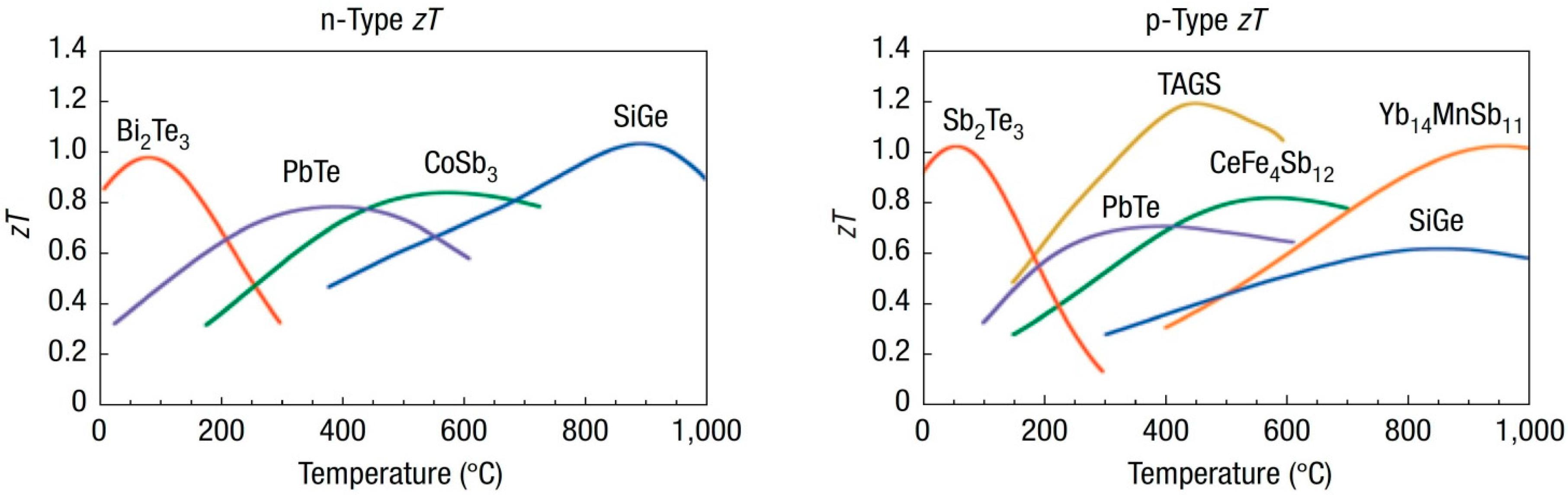
Today, semiconductors are the most used class of materials because these combine the described requirements, but also in this class there are differences between the materials which affect mainly the best performance temperature. In
Figure 1 the temperature dependence of different n- and p-doped materials is shown. The differentiation between n- and p-doped materials is important, because n-doped materials have a negative Seebeck coefficient, p-doped materials a positive one and therefore not electrons but holes are moveable. It is obvious that there is not an all-in-one solution that is powerful in a wide temperature range. Bismuth telluride (BiTe) is the most suitable material for using the heat flows inside of a satellite because the temperatures will be lower than 100 °C. This is also the temperature area of typical terrestrial low power energy harvesting applications. Therefore, in the last years a lot of commercial thermoelectric generators appeared on the market.
2.3. Thermoelectric Devices
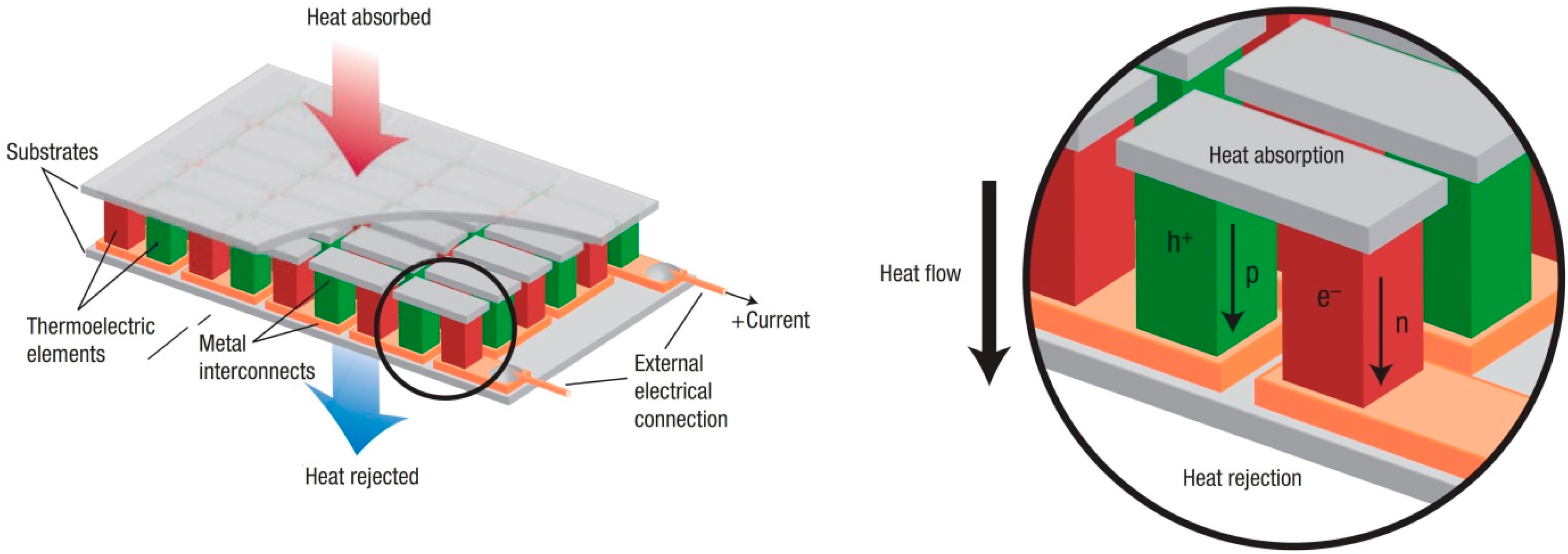
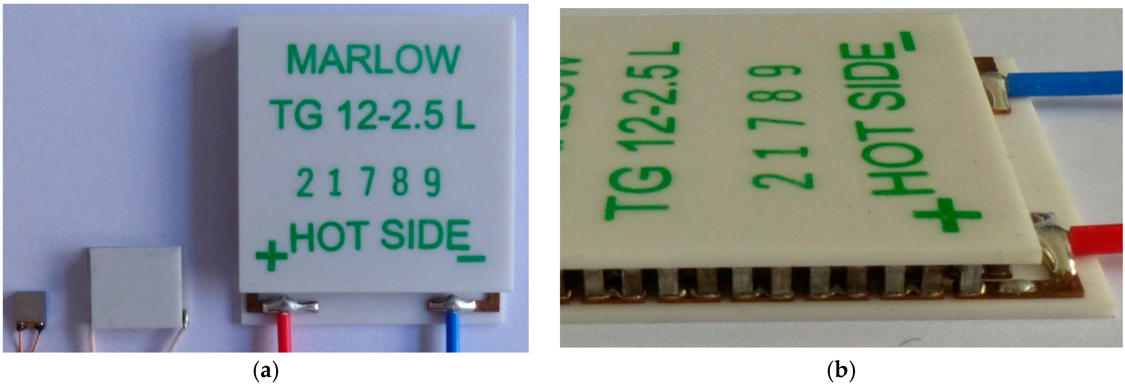
The most common design of a thermoelectric generator is shown in
Figure 2. Metal interconnections are printed on an alumina oxide substrate. On top of every one of these (copper) interconnections are both: a p- and an n-doped leg. Here a combination of a p- and an n-doped leg is called a thermocouple. Inside a thermoelectric generator a lot of thermocouples are connected electrically in series and thermally in parallel. On the top side of the generator a further substrate is connected. Both substrates have to be parallel because they establish the thermal interface of the generator. The heat flow crosses the substrate; therefore this design is called crossplane. Generators commercially available nowadays are mostly part of this class. They can be manufactured in various dimensions. The smallest device have a cross section of around 3 mm × 3 mm with a height of 1 mm, the functional material has a height of 19 µm. These devices are made by a thin-film process inspired by processes from the chip industry. Because these small devices are very sensitive against mechanical stress bigger devices (so called bulk-device) are preferred for most applications. Bulk-TEGs are made of differential parts that are soldered in semi-automatic processes. In
Figure 3 different Bulk-TEGs are shown, along with details like the solder joints.
Another basic design of TEGs is the so called in-plane device. Inside these devices the heat flow is parallel to the substrate which is commonly a flexible film or foil like kapton. The main advantage of such devices is their flexibility. Thus, gaps can be bridged without inserting a new mechanical connection, which is important for an easy integration, but the efficiency of such a design is lower than that of crossplane devices, because only a part of the available heat flows through the functional material, the remaining heat passes the device through the substrate that cannot be used for power generation. Also the manufacturing process differs strongly from that of crossplane devices. It is dominated by cost-effective printing processes like screen- or inkjet-printing.
3. Characterisation of Thermoelectric Generators
3.1. Test Bed for the Characterisation of Thermoelectric Generators (TEGs)
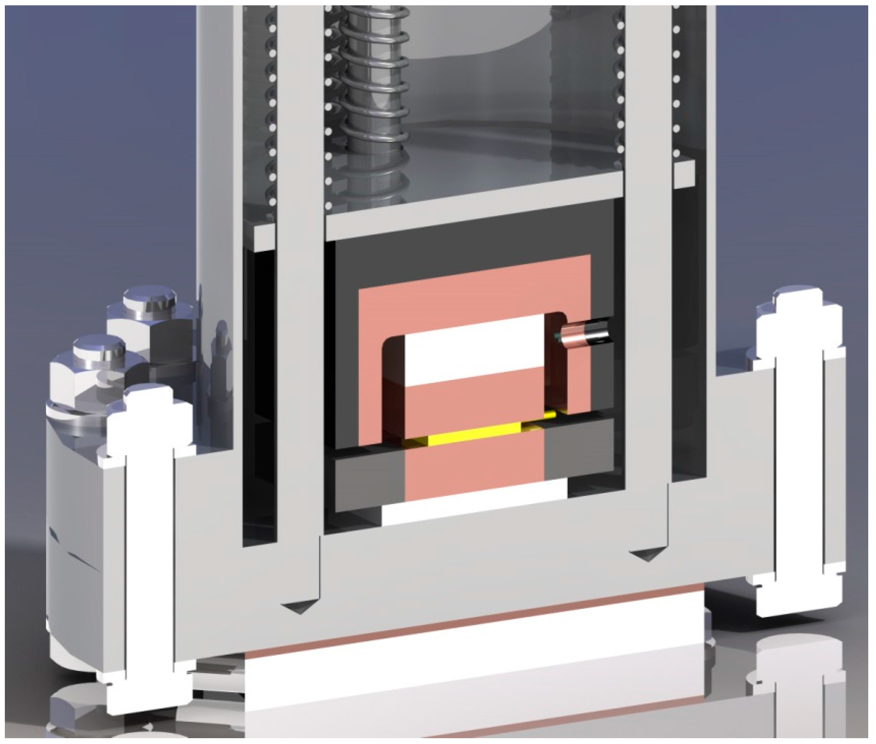
For the electrical characterisation of TEGs a test bed was developed (
Figure 4). Inside the test bed up to four TEGs can be evaluated in parallel; thereby the temperatures on the hot and the cold side of the TEG are set as boundary conditions. The hot side temperature is provided by a Peltier cooler in combination with a heat exchanger. On the hot side a foil heater provides the temperature. Both temperatures are measured by Pt1000-sensors. While testing the voltage of a TEG is measured. Up to five load resistances can be automatically connected to the TEG to determine the generated power and electric current. Although the thermal resistance of TEGs cannot be measured, it is not a major problem for our studies due to the uncertainties in thermal contacts in a real application. Therefore information from the datasheets will be used to determine the heat flow at adjusted temperatures. Because we focus our studies on space applications, the test bed can be integrated in a vacuum chamber. This is also necessary to eliminate errors caused by (forced) convection. Detailed description of the test bed can be found in [
8,
9].
3.2. Current and Voltage
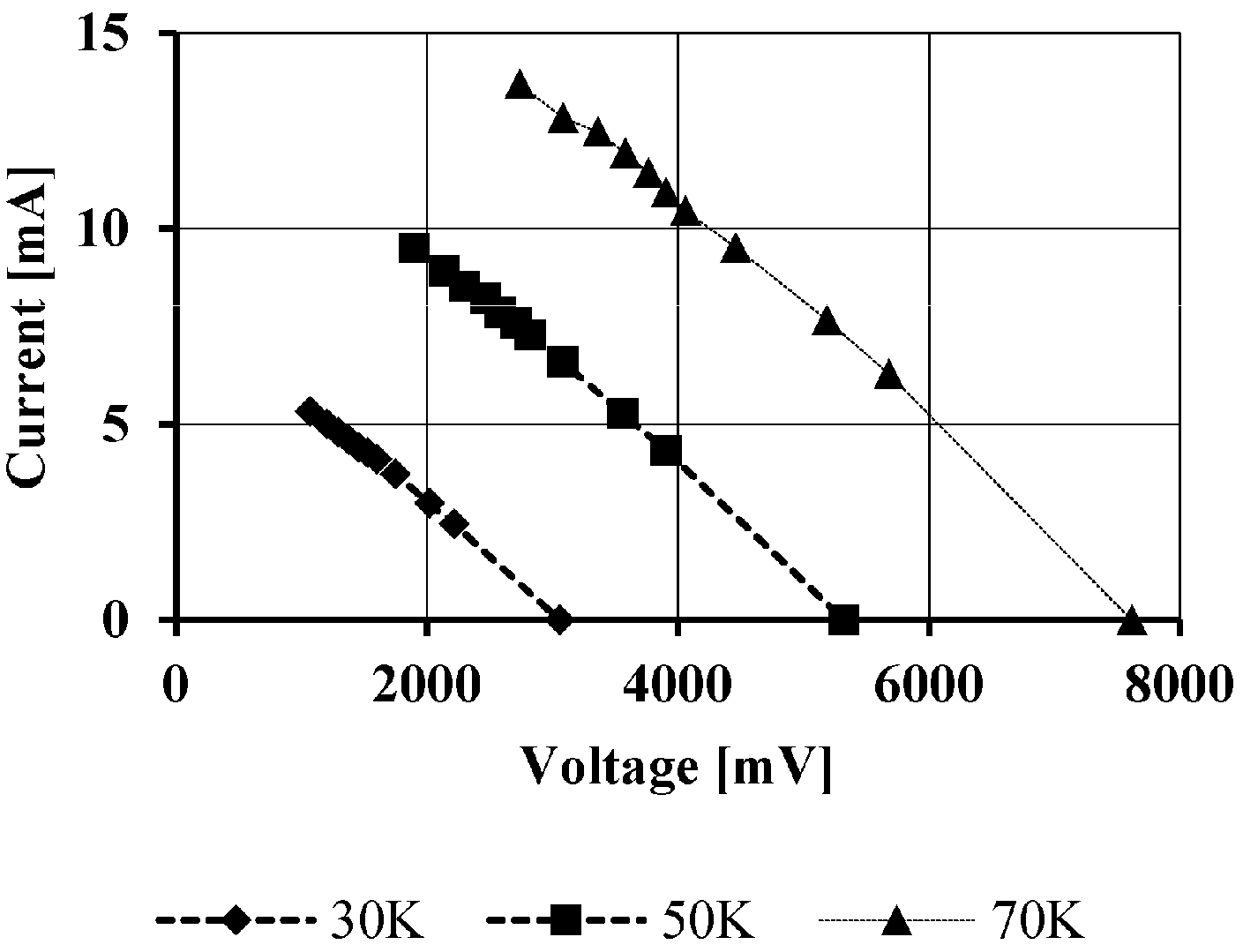
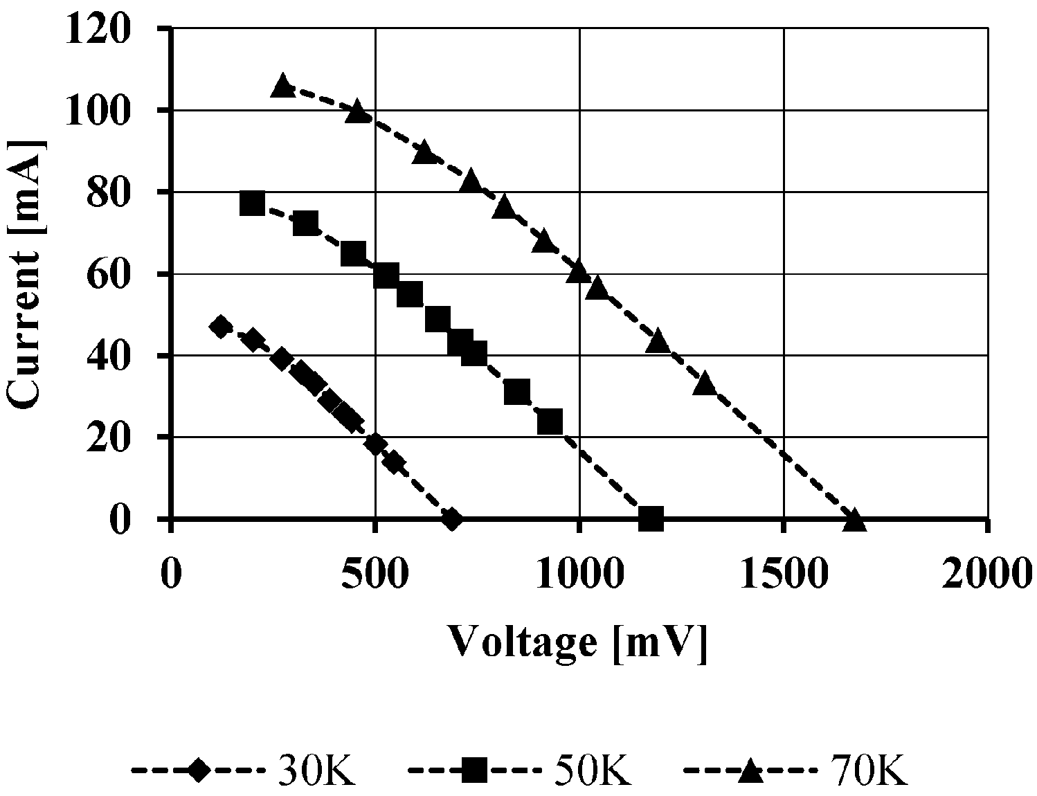
The voltage-current-characteristics of a generator include different aspects like the open-circuit-voltage, the generated power and the internal resistance. The
V-
I-characteristic of TEGs is nearly linear and is shifted parallel by changing the heat flow or rather the temperature gradient. This behaviour is shown by the example of a small Bulk-TEG in
Figure 5. The tested TEG has a cross-area of 10 mm × 10 mm and a high of ca. 2 mm [
10]. A major challenge for using the generated power is given by the low voltage. The expected temperature gradients are mainly lower than 30 K, therefore the current will also decrease. Due to the required constant higher voltage for supply of consumers, the voltage has to be converted. It is assumed, that the conversion efficiency is ca. 30% [
11,
12]. One approach to increase the output voltage of the generator is given by thin-film-device due to the high amount of thermocouples. A characteristic under similar conditions is shown in
Figure 6. Since a lot of small thermocouples are realised in a small area the internal resistance increases strongly. This can be seen in the lower generated current. For this reason we need to consider between lower conversion losses but lower generated current (thin-film device) and higher losses at higher current.
3.3. Electrical Power and Resistance
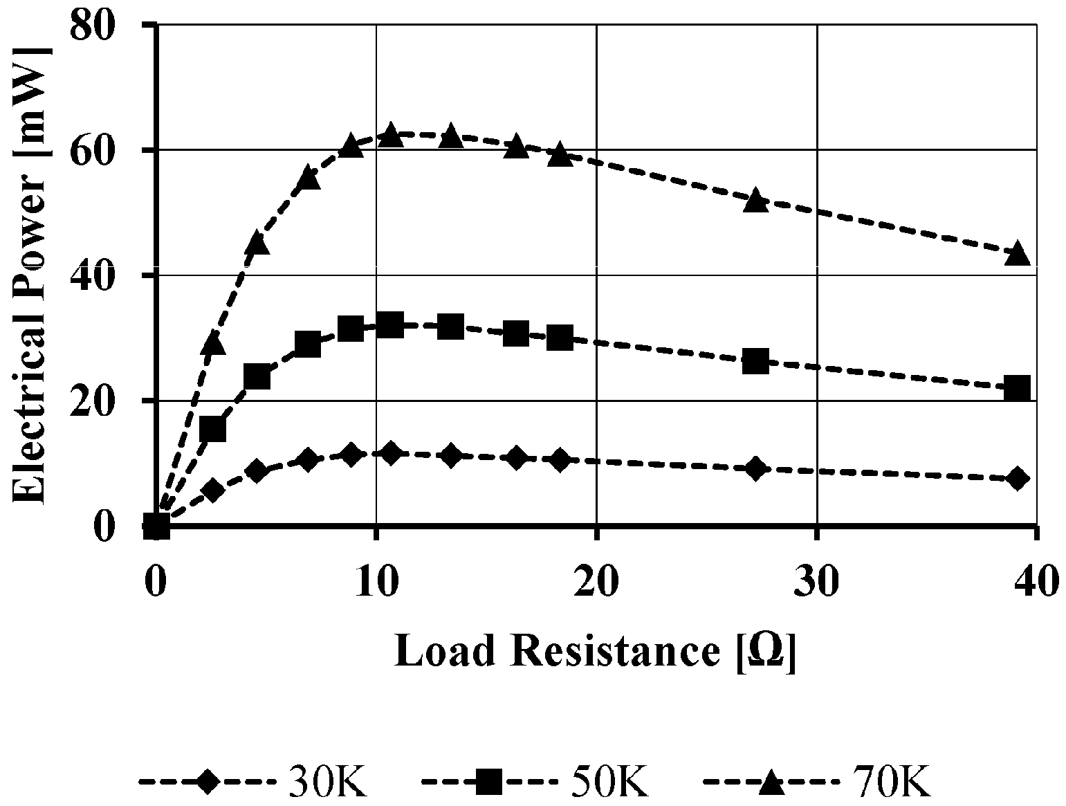
Beside the V-I-characteristic the generated electrical power is the most important value for the evaluation of the potential of thermoelectric generators. Power is only generated if a load is connected to the generator. Therefore it is mandatory to consider the load resistance when talking about the electrical power. In most applications it is important to generate as much power as possible due to the fact that the power level is low in general. The maximum electrical power can be generated if the load resistance is equivalent to the connected internal resistance which is temperature dependent. Thereby the load resistance is not given by the consumer but by the power converter. To maximise the power output a maximum-power-point-tracking (MPPT) can be foreseen. Of course, this produces additional small losses. In particular for transient thermal conditions a MPPT could be interesting. Nevertheless, it is important to realise a (rough) load matching.
Figure 7 shows the load-dependent behaviour of a small Bulk-TEG. It is obvious that there is a distinct maximum power point. If the connected load is smaller than the internal resistance the generated power drops down significantly. In contrast higher load resistances have a smaller influence on the generated power. Therefore the load resistance shall be a little bit larger than the internal one. This applies particularly to applications without a MPPT.
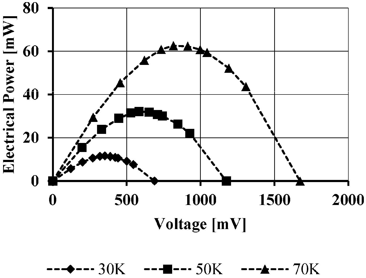
As discussed above the available voltage is an important evaluation criterion. Therefore in
Figure 8 the electrical power of a small Bulk-TEG depending on the voltage is shown. This graph underlines the maximum power point again that amounts to half of the open-circuit voltage.
Summarising, the generated electrical power depends strongly on the electrical conditions (especially on the load resistance). Of course, for a high power output a high heat flow or temperature gradient is also mandatory. As discussed, the available temperature gradient in an application will be mostly lower than 30 K, in ideally 10 mW is generated. Furthermore, it is reduced by the conversion losses.
3.4. Specific Power and Efficiency
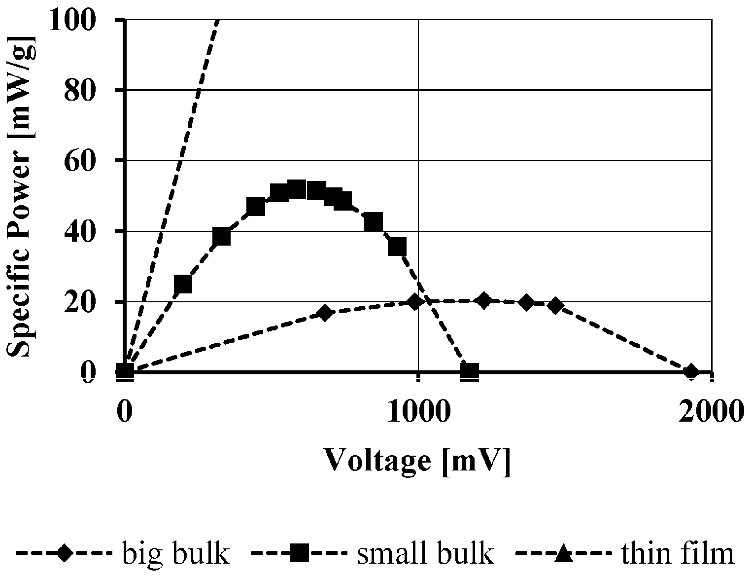
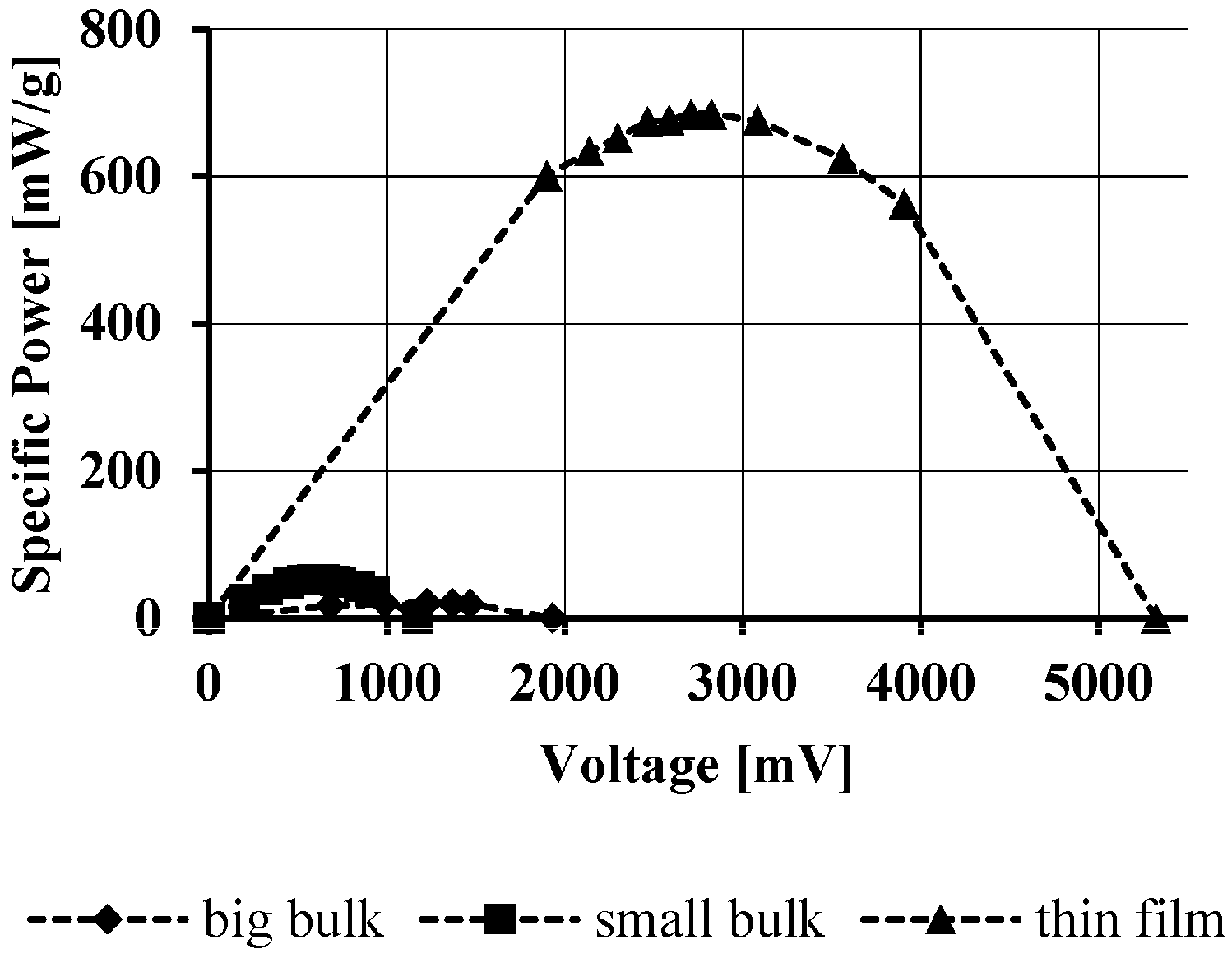
Particularly for space application lightweight technologies are mandatory, so the specific power (W/kg) of generating devices and specific electrical energy of storing devices have to be increased. Therefore, the electrical power shown in
Figure 8 is divided by the weight of the device that is shown in
Figure 9 and
Figure 10. For the calculation the mass of the device without cables or other infrastructure was taken. The mass is 0.03 g for the thin-film device, 0.61 g for the small bulk device and 10.69 g for the big bulk device. There are big differences between the two classes of TEGs: the thin film device achieves a specific power of 700 mW/g, the Bulk-TEGs start at 52 mW/g. But it could be possible, that the bulk devices generate benefits at higher heat flows due to the higher electrical current. In these cases the lower internal resistance of the TEGs could decrease losses. Nevertheless, the later discussed applications work only in low power conditions, therefore the thin-film devices are superior in terms of the specific power.
In energy harvesting the efficiency is not crucial since the heat is available anyway. Even at low efficiencies TEGs will generate benefits if their power can be used. The efficiency is lower than 2% under the conditions mentioned in
Figure 8.
3.5. Thermal Cycling and Vibration
Thermoelectric generators in space application underlie different mechanical loads during the missions. Thereby vibrations and thermal cycling are particularly challenging. While vibrations occur only during a short period of time during launch, thermal cycling loads has to be taken into account over the whole mission time. Thermal cycling results in micro cracks within the material and at junctions of different materials. They are caused by different thermal expansions and result in mechanical stress. Consequently the internal resistance increases until the conduction is interrupted. The mechanical stress is caused by two mechanisms: inside the functional material a temperature gradient arises along the height of a leg that causes in mechanical stress. Thus the cracks are parallel to the height of the leg. However, at junctions of different materials the temperature is constant but the coefficient of thermal expansions (CTE) differs abruptly. Mechanical stress is also caused and cracks occur on the junction layer. This effect is reinforced by a diffusion barrier that is located between the functional material and the copper contacts [
13]. The crack growth is aided by the brittle function material and the dynamic occurrence of the mechanical stresses by thermal cycling. An estimation how many cycles can be suffered cannot be made due to the strong dependence on the thermal conditions, the device and the mechanical interface. Studies of other institutes achieved up to 45,000 cycles until the device failed. For detailed information and studies see [
14].
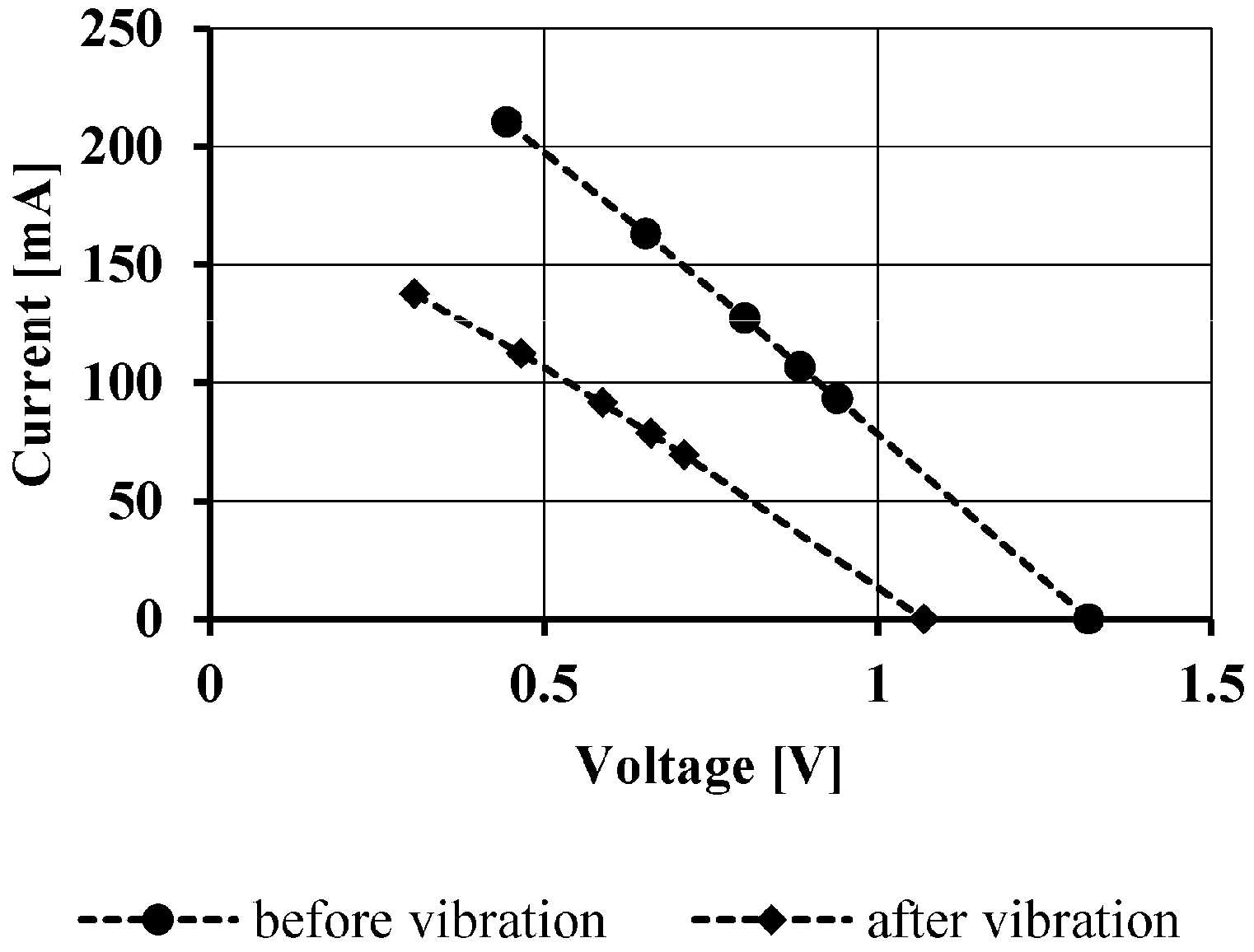
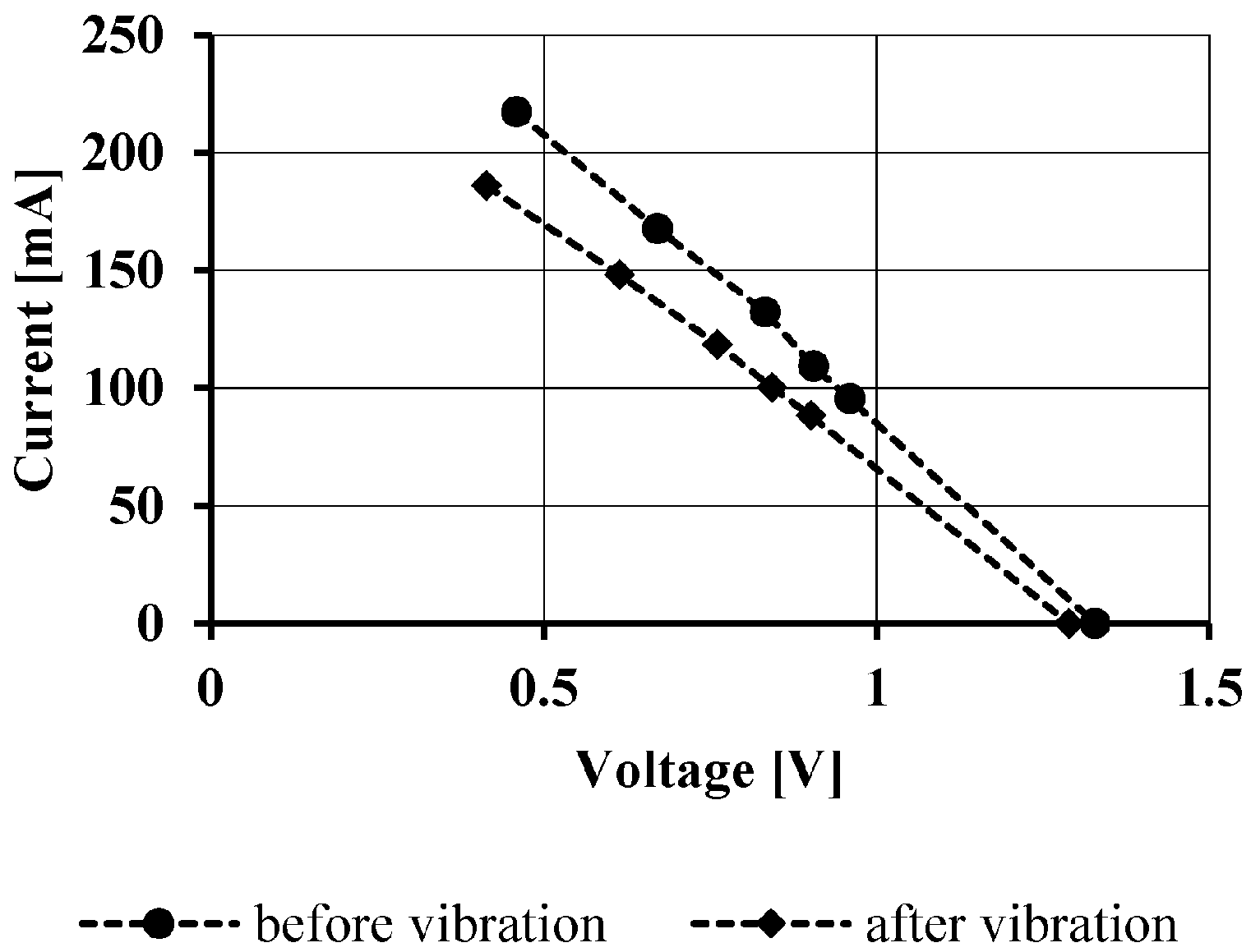
First vibration tests of TEGs were executed at the Institute of Aerospace Engineering. Several big and small bulk devices were exposed to vibrations vertically and horizontally to the substrate. Consequently the mechanical loads can be distinguished between tension/pressure and shear. All devices were glued on a thin alumina plate for mounting on the shaker, than characterised as discussed above, exposed to the vibration and characterised again to determine differences. Thereby the loads consisted of sinus vibration (3.7 g
2/Hz up to 200 Hz) and random vibrations (up to 0.035 g
2/Hz up to 2000 Hz). Both test were executed consecutively, every 2 minutes. In
Figure 11 and
Figure 12 the
V-
I-characteristics of the big bulk device are shown. It is obvious that in both vibration directions the curve drops and that the vibration vertical to the substrate will be more critical. This behaviour can also be observed at a tested small device. For a better understanding the top substrates of the devices were removed and the cracks were analysed in detail. It was obvious that a majority of the legs broke at the interface between functional material and copper contact. Thus, the interface is not only at thermal cycling a mechanical problem but also at vibration loads. Optical examinations show cavities in the solder of the interface. So one explanation can be the insufficient soldering of the components. In a further material analysis (EDX) of the fractured surface nickel was identified. It must not be used for soldering since nickel solders have a melting point over 900 °C and therefore it is not suitable for soldering BiTe with a considerable lower melting point. It can therefore be assumed, that the nickel is an element of a diffusion barrier between the copper contact and functional material to prevent an arising bridle intermetallic phase. This is a common approach to increase the thermal stability of TEGs but it seems to decrease the mechanical resistance.
4. System Studies
4.1. Occurring Heat Flows in Commercial Satellites
For the evaluation of the principle application potential it is important to have some information about available heat flows that can be used for power generation. Since satellites are mostly individual models with their own orbits it is only feasible to make reliable statements about general thermal conditions. Nevertheless, it is a good base to evaluate the potential for a specific application later on.
For this analysis a detailed thermal model of the European satellite Sentinel-2 (S2) was used [
15]. In a first step the model was calculated without any modifications to generate some information about available heat flows. In a second step TEGs were integrated into the model by changing the thermal resistance between different knots. Thereby the generated electrical power and temperature changes were calculated. The latter is important to have some information whether the integration of TEGs has an influence on the thermal housekeeping. In all cases different modes were calculated. The hot case, the cold case and the safe mode were considered. Thereby the evaluated locations of integration of TEGs can be divided into three groups:
Between an electronic unit and the floor which it is mounted on;
Between two redundant electronic units;
Between the two outer surfaces of the solar panel.
In the first case a TEG was integrated between an electronic unit and the floor which it is mounted on. Thereby the majority of the heat that is generated in the unit is given to the floor via the mechanical interface. Therefore the interface has to be a good thermal conductor. The TEG should be thermal in parallel, but for increasing the available heat flow through the TEG the thermal conduction to the floor has to be decreased. In most cases this is not possible to prevent the unit against overheating. In summary this kind of integration is promising concerning available heat flows but not suitable due to the influence on the thermal housekeeping of the satellite.
More interesting is the integration of a TEG between two redundant electronic units. For a higher reliability important components are often duplicated. In Sentinel-2 these units are located side by side but only one of them is working. For an evenly aging the satellite switches between the two units periodically. Such a design and operation can be found in a lot of satellites. By operating the unit heat is produced. However the inactive unit is significantly colder. Therefore a heat flow occurs if a TEG is integrated between the active and the inactive component. This heat flow can be used for generating power and also to adjust the temperatures of both units. In the studies according to Sentinel-2 up to 50 mW electrical power can be generated. But in most configurations that were analysed the electrical power is in the range of 10 mW. Nevertheless, using this heat flows is an elegant way for integrating TEGs in satellites. The main disadvantage is that the power is only available if the satellite and its components are working. In these cases power from the solar panels is also available and therefore some milliwatts do not cause a significant change.
The third investigated group of potential applications is represented by an attachment to the solar panel. Sentinel-2 has one traced solar panel. Therefore inside the structure of the panel a high heat flow occur due to the fact that a part of the absorbed solar radiation is heat that has to be radiated to space. This is done by the backside of the solar panel. The heat flow is distributed on the whole cross sectional area of the panel, so the specific heat flow is low. To use the heat for conversion into electrical power it is mandatory to focus on these heat flows. This can be done by decreasing the thermal conductivity between the two surfaces and the integration of thermoelectric generator in parallel to this conductor. The main problem of this approach is that the solar cells will become hotter than in the standard configuration. Since the efficiency of solar cells decreases with higher temperatures, there could be a negative impact on the available electrical power of the satellite. Another approach is the usage of flexible TEGs that are mounted at the front surfaces thermal in parallel to the structure. Even in this case the thermal conductivity of the panel structure has to be decreased. In our studies we analysed the electrical potential at the standard configuration, at halved thermal conductivity and at an assumed adiabatic structure. Thereby the TEGs have a thermal conductivity of a Kapton foil and adapted electrical parameters. The main results of these studies are given in
Table 1. In total 48 TEGs were evenly distributed. It is obvious that in the adiabatic case the amount of generated energy is bigger than in the other cases. But also the maximum temperature increases strongly. A middle course is reducing the internal thermal resistance of the panel since the temperature increases only by 3 K. By using the standard configuration it would be possible to generate some electrical energy and having a positive impact on the thermal housekeeping of the solar panel. Due to the low impact on the manufacturing and design of such panels it would be a preferred application.
In summary, inside the satellite usable heat flows are available but only some of them have the potential for energy harvesting due to the impact on the thermal housekeeping and design of the satellite. In these cases, especially high heat flows cannot be used.
4.2. Autonomous Systems Powered by Thermoelectric Generators
To generate benefits by using thermoelectric generators in an energy harvesting content it is mandatory to have electrical loads that can be supplied. The main challenge is the low available power that is reduced by the required conversion as discussed above. Therefore a feed-in of the electrical power into the main power system is not feasible. Nevertheless autonomous systems can be supplied by the generated power. Such systems do not exist on today’s satellites but there are some requirements for these: There should not be any electrical interface to the satellite, since by this interface the system can also be powered by the satellite. Furthermore these systems should not replace common technologies but provide new features. Possible systems could be:
An independent thermal control would increase the reliability of the satellite. Today an active thermal control is only possible if the satellite is in a nominal working mode. By TEGs different actuators can be driven to switch heat flows or changing optical surfaces. An approach is to power electrochromatic devices (ECD) that change their optical properties depending on an applied voltage [
16,
17]. Only during the switching power is required. By ECDs radiators can be controlled and thereby the radiated thermal power. Such systems are of particular interest since heat flows are always available that can be used directly or in a thermal bypass to avoid higher thermal resistances.
An independent and simple communication system could enable a basic communication between the satellite and a ground station. In case of a failure of the satellite or its subsystems this system can send fundamental information (temperatures, filling level of the tank, etc.). This information can be used to detect the failure, to repair the satellite or to provide a disposal manoeuvre to avoid new space debris. It is also conceivable that telecommands are received, processed and different simple tasks are executed. An example for such tasks is the controlled discharging of the batteries that is determined in international standards and agreements. A detailed description of such systems can be found in [
18].
Another conceivable application is an autonomous attitude determination. Particularly coarse earth sun sensors are suitable to be powered by TEGs [
19]. Such sensors consist of two adiabatic mounted equal surfaces with different coatings. So the temperatures driven by the radiation (earth, sun) of both areas differ. Around the satellite six of these sensors are mounted. By measuring the temperature differences between the areas of each sensor, the attitude can be determined with an accuracy of more than 10°. Such sensors are very simple and have a low power demand. By connecting the surfaces via a TEG, a heat flow occurs that can be converted into electrical power. Thereby an independent and own power supply can be realised. Of course, the temperatures drop down, so an optimisation has to be executed. Such raw attitude information can for instance be used in safe mode or LEOP and an information can be send by the independent communication system to earth as discussed above.
All applications need next to the TEG an electrical infrastructure that includes a power management for the conversion and a storage device. It can be expected that generating and consuming of electrical power is not simultaneously. Therefore the power has to be stored. Due to the transient thermal conditions there will occur a lot of charging ad discharging cycles. Since batteries are very sensitive against electrical cycling, they need to have a high mass to fulfil the requirements [
20,
21]. However, supercaps are suitable for these applications. Next to the insensitivity against cycling they have not any requirements on the temperature [
22,
23], but compared to batteries, the self-discharging is higher. Furthermore the specific energy is quite low. Next to the compensation of a power mismatch supercapacitors can be used if a low heat flow occurs over a long time and the supplied system only works for a short time with a higher electrical power.
4.3. Small Satellites
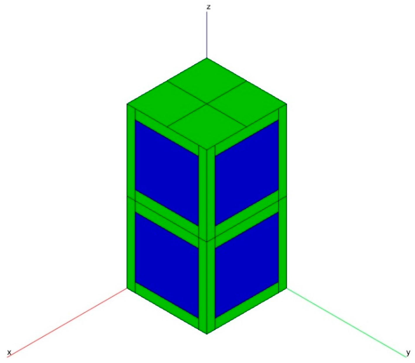
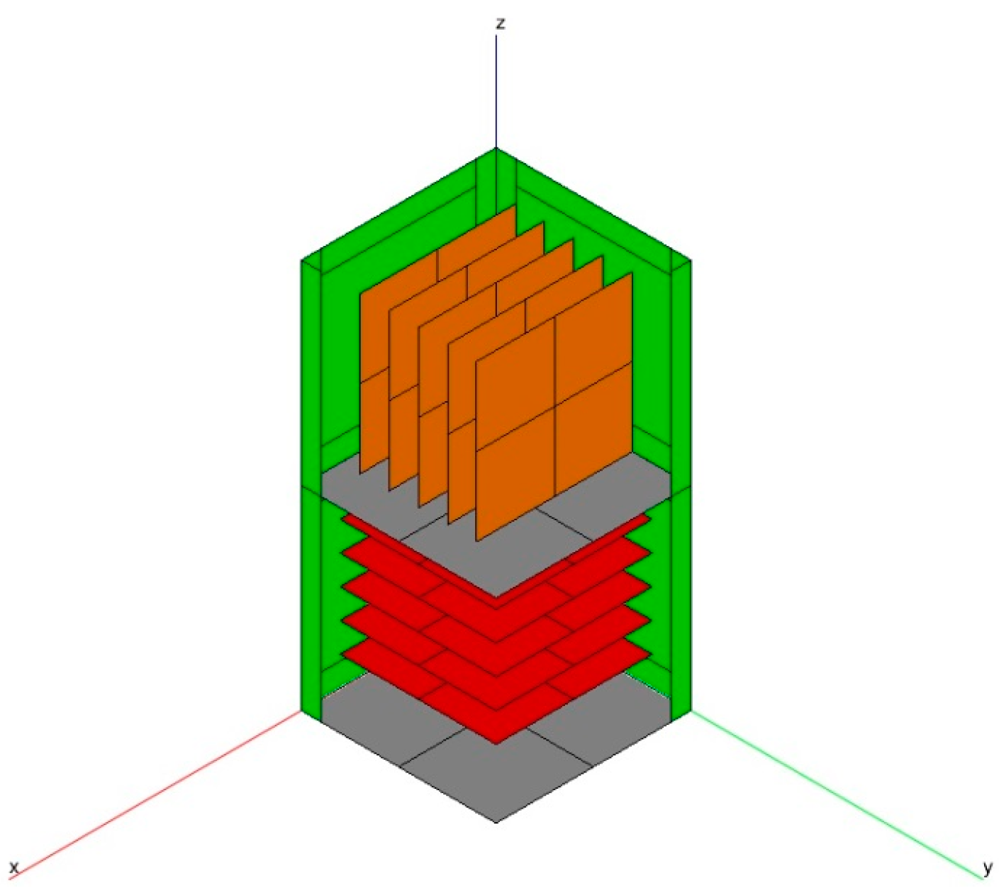
Considering the available electrical power of satellites Cubsats seem to be satellites on which TEGs could provide the main electrical power system. Cubesats have an installed power lower than 5 W. Therefore also some milliwatts of additional power have a high impact on the efficiency of the satellite. This examination is based on the CubeSat of the Institute of Aerospace Engineering at TU Dresden was used same thing written three different ways in two sentences—pick a style and use it consistently. This is a double unit Cubesat (100 mm × 100 mm × 200 mm) that has solar cells on four surfaces. Characteristic are the two PCB stacks that have a different orientation. In this configuration two different designs were taken into account. The thermal model as shown in
Figure 13 and
Figure 14 were built up in ESATAN-TMS and includes 86 knots. Different conductors between the outer surfaces and PCBs are implemented; the view factors were determined by the Monte-Carlo-Method. On the PCBs different configurations of heat loads according to power consumption of the satellite were foreseen. Next to the mechanical configuration different operation modes were investigated. The orbit is a high inclined circular orbit (600 km,
i = 70°) that is typical for such scientific missions. Also a rotation around the flight axis of 0.5°/s was considered. A verification of the model was not executed due to the greatly simplified internal design. This is mandatory because the optical and geometrical properties are very complex (e.g., cables) and therefore the calculation is both, very time-consuming and unreliable. But the representation accuracy is adequate for general results.
Although different locations of integration were considered, the potential for an energy harvesting on small satellites is quite low with today’s technologies. The temperature gradient that occurs at the integrated TEG is in all cases lower than 3 K. The highest thermal potential with up to 3.5 K arises if two facing solar cells are connected directly by a TEG. Due to the integration effort and specific power this is only a theoretical approach. The main problem of using the heat inside small satellites is their compact design. In contrast to big satellites the whole internal space of small satellites is filled by PCBs and cables. Consequently the heat flow is very diffuse. A great effort would be necessary to concentrate the heat flows and guide it through a TEG. Since in reality there are much more thermal contacts between PCBs and the outer surfaces like connectors or cables, the heat flows will be more diffuse.
In summary, an application of TEGs in small satellites is not promising today due to the diffuse heat flows. Nevertheless, a technology demonstrator will be launched in 2017 on a small satellite built by TU Dresden. The demonstrator is located under a solar cell that is adapted to this application. The assumed temperature gradient of 3 K is not high enough to feed in the generated electrical power into the main power system. But test results show that it is high enough to characterize the thermoelectric generator under real space conditions. After that mission the results will be used for further experimental setups and are therefore the next step to bring TEGs into space in an energy harvesting application.
5. Conclusions
Inside the structure of satellites heat flows occur that are driven by environmental (sun radiation, etc.) and operational loads (electronics, etc.). These heat flows are unused so far, although there is a potential for generating electrical power in general. Thereby the generated electrical power can be used for an increase of the satellites efficiency by a feed-in to the main electrical power system. Because of the low efficiency of available TEG technology this is not sufficient today. Also inside small satellites with a very low power demand the generated power is relatively low due to the diffuse heat flows. Another approach is to use the generated power to increase the reliability of the satellite by implementing new systems. These systems should have a low power demand and no electrical interface to the satellite. Tasks of such systems could be an autonomous thermal control or a redundant communication system as discussed above.
In general it is feasible to use low power thermoelectric generators that are manufactured for terrestrial applications in space. Examinations of the device behaviour under thermal cycling and vibration loads show that they can withstand them if they are exposed to medium loads. The diffusion barrier between the copper contacts and the functional material was identified as a main weakness.
Besides the generator a power-management and an electrical storage system is required. The power management converts the transient and low voltage into a constant usable voltage. At such low voltages the efficiency of this process is in the range of 30%. Storage is used for balancing the power mismatch because the time of available and required power is not synchronised. A promising storage is presented by supercapacitors due to their insensitivity to temperature and loading cycles.
It can be expected that generators with better electrical performance will appear on the market. But according to the physical basics their efficiency will also be limited in future. Another approach is to develop the manufacturing process towards printing. Consequently large area devices are feasible; therefore the heat does not to be concentrated. Furthermore functional surface coatings could be conceivable [
7,
24,
25].
In a next step a technology demonstrator will be launched in 2017 on board of small satellites as discussed above. The generated power will not be used but the TEGs will be characterised under real space conditions. New knowledge about the behaviour and thermal potential of space applications for an energy harvesting is expected.
Acknowledgments
The authors acknowledge the German Space Administration for funding the project “Potential of Thermoelectric Generators for Energy Harvesting on Space Systems” and also the European Commission for funding the NanoCaTe project.
Author Contributions
Marian v. Lukowicz did already the main work like the most examinations and writing the paper. Elisabeth Abbe did some experimental analysis concerning the discussed application, especially she made test of screen printing of thermoelectric generators. Tino Schmiel had the original idea for the idea in the paper and was in charge of managing the research project. Martin Tajmar discussed the appilcations, the ideas and gave some new approaches.
Conflicts of Interest
The authors declare no conflicts of interest.
References
- Messerschmidt, E.; Bertrand, R.; Pohlemann, F. Raumstationen: Systeme und Nutzung; Springer-Verlag: New York, NY, USA, 1997. [Google Scholar]
- Snyder, G.J.; Toberer, E.S. Comply thermoelectric materials. Nat. Mater. 2008, 7, 105–114. [Google Scholar] [CrossRef] [PubMed]
- Hyder, A.K.; Wiley, R.L.; Halpert, G.; Flood, D.J.; Sabripour, S. Spacecraft Power Technologies; Imperial College Press: London, UK, 2003. [Google Scholar]
- Lange, R.G.; Carroll, W.P. Review of recent advances of radioisotope power systems. Energy Convers. Manag. 2008, 49, 393–401. [Google Scholar] [CrossRef]
- Goldsmid, J. Introduction to Thermoelectricity; Springer: Heidelberg, Germany, 2010. [Google Scholar]
- Rowe, D.M. Handbook of Thermoelectrics; CRC Press: Boca Raton, FL, USA, 1995. [Google Scholar]
- He, W.; Zhang, G.; Zhang, X.; Ji, J.; Li, G.; Zhao, X. Recent development and application of thermoelectric generator and cooler. Appl. Energy 2015, 143, 1–25. [Google Scholar] [CrossRef]
- Von Lukowicz, M. Konzeption und Inbetriebnahme eines Teststandes zur Bestimmung der Leistungskenndaten von Thermoelektrischen Generatoren. Diploma thesis, TU Dresden, Dresden, Germany, 2011. [Google Scholar]
- Von Lukowicz, M.; Rosenfeld, M.; Schmiel, T. Evaluation of characteristics of thermoelectric generators for potential applications for low power demands in space. In Proceedings of the 31st International and 10th European Conference on Thermoelectrics, Aalborg, Denmark, 9–12 July 2012.
- Thermo Electrical Generator TEG1-9.1-9.9-0.2/100; Eureca Messtechnik GmbH: Köln, Germany, 2004.
- LTC3107-Ultra Low Voltage Energy Harvester and Primary Battery Life Extender; Linear Technology: Milpitas, CA, USA, 2013.
- LTC3109-Auto-Polarity, Ultralow Voltage Step-Up Converter and Power Management; Linear Technology: Milpitas, CA, USA, 2010.
- Nong, N.V.; Hung, L.T.; Han, L.; Ngan, P.H.; Pryds, N. Characterization of the contact between Bi2Te3-based materials and lead-free solder alloy under thermal cycling. In Proceedings of the 34th Annual International Conference on Thermoelectrics (ICT 2015) and 13th European Conference on Thermoelectrics (ECT 2015), Dresden, Germany, 28 June–2 July 2015.
- Hatzikranoitis, E.; Zorbas, K.T.; Smaras, I.; Kyratsi, T.; Paraskevopoulos, K.M. Efficiency study of a commercial thermoelectric power generator (TEG) under thermal cycling. J. Electron. Mater. 2010, 39, 2112–2116. [Google Scholar] [CrossRef]
- Drusch, M.; Del Bello, U.; Carlier, S.; Colin, O.; Fernandez, V.; Gascon, F.; Hoersch, B.; Isola, C.; Laberinti, P.; Martimort, P.; et al. Sentinel-2: ESA’s optical high-resolution mission for GMES operational services. Remote Sens. Environ. 2012, 120, 25–36. [Google Scholar] [CrossRef]
- Larsson, A.-L. All-Thin-Film Electrochromic Devices for Optical and Thermal Modulation; Acta Universitatis Upsaliensis: Uppsala, Sweden, 2004. [Google Scholar]
- Monk, P.; Mortimer, R.; Rosseinsky, D. Electrochromism and Electrochromic Devices; Cambrige University Press: Cambrige, UK, 2007. [Google Scholar]
- Von Lukowicz, M.; Schmiel, T.; Rosenfeld, M.; Heisig, J.; Tajmar, M. Characterisation of TEGs under extreme environments and integration efforts onto satellites. J. Electron. Mater. 2015, 44, 362–370. [Google Scholar] [CrossRef]
- Technische Universität München. GOCE Projektbüro. Available online: http://www.goce-projektbuero.de/8102--~goce~Goce~Mission~Vorgaengermission~Erd_und_Sonnensensor.html (accessed on 10 July 2015).
- Technical Marketing Staff of Gates Energy Products, Inc. Rechargeable Batteries Applications Handbook; Elsevier: Oxford, UK, 1998. [Google Scholar]
- Collins, D.H. Batteries 2: Research and Development in Non-Mechanical Electrical Power Sources; Elsevier: Amsterdam, The Netherlands, 2013. [Google Scholar]
- Beguin, F. Supercapacitors: Materials, Systems and Applications; Wiley-VCH: Weinheim, Germany, 2013. [Google Scholar]
- Faraji, S.; Ani, F.N. The development supercapacitor from activated carbon by electroless plating—A review. Renew. Sustain. Energy Rev. 2015, 42, 823–834. [Google Scholar] [CrossRef]
- Stepien, L.; Roch, A.; Schlaier, S.; Dani, I.; Kiriy, A.; Simon, F.; von Lukowicz, M.; Leyens, C. Investigation of the thermoelectric power factor of KOH treated PEDOT:PSS dispersions for printing applications. Energy Harvest. Syst. 2015, 3, 101–111. [Google Scholar] [CrossRef]
- Stepien, L.; Roch, A.; Schlaier, S.; Abt, M.; Hoch, C.; Dani, I.; Ngo, N.V.; von Lukowicz, M.; Leyens, C. Dispenser printed thermoelectric generators. In Proceedings of the 34th International and 13th European Conference on Thermoelectrics, Dresden, Germany, 28 June–2 July 2015.
© 2016 by the authors; licensee MDPI, Basel, Switzerland. This article is an open access article distributed under the terms and conditions of the Creative Commons Attribution (CC-BY) license (http://creativecommons.org/licenses/by/4.0/).


