1. Introduction
Most of the fuel energy in an internal combustion engine is lost as heat. These losses can be reduced by using waste-heat recovery (WHR) systems, which have been widely discussed and investigated in literature within the last decade. An overview of the activities in the field is provided in the review articles published by Sprouse and Depcik [
1] and Wang et al. [
2]. Systems based on the Rankine cycle have been identified as the most appropriate for vehicle applications, in terms of efficiency, maturity and cost. Such systems could potentially increase the powertrain efficiency of long-haul trucks (the operating conditions of which are considered particularly suitable for heat recovery) by up to 30% [
2]. Suitable waste heat sources referred to in case of a combustion engine are the engine coolant, charge air cooler, tailpipe exhaust gas and exhaust gas recirculation (EGR) system (with increasing waste heat temperature in this order). Horst et al. [
3] noted that both charge air cooler and EGR are particularly attractive for heat recovery applications, since the recovered energy is removed from the load on the vehicle cooling system, while utilizing tailpipe exhaust gas adds additional heat to it.
Besides the choice of the heat source, the two main components that affect the conceptual design and performance are the working fluid used in the cycle and the expansion device, which is used to expand the generated vapor and produce the output work of the cycle. Factors that affect the choice of these components are the boundary conditions and practical requirements of the heat-recovery system [
4,
5]. The nature of the working fluid strongly affects these boundary conditions and requirements: those of the organic Rankine cycle (ORC), which uses organic working fluids, differ significantly from those for the traditional steam Rankine cycle using water as the working fluid.
Panesar et al. [
6] compared organic working fluids for a Euro 6 heavy-duty diesel engine concept with a high EGR rate, and concluded that acetone, R30 and R1130 provided better performance (under the chosen boundary conditions) than water, which was included in the tests for comparative purposes. The drawback of water was the large amount of heat required to evaporate and superheat it, which reduced overall conversion efficiency. However, the cited authors noted that water also had substantial advantages, including its high thermal conductivity and absence of health, environmental and safety issues. These advantages were also highlighted by Stobart and Weerasinghe [
7], who decided that water would be the most practical fluid to use in vehicle applications if the freezing issue could be overcome. Furthermore, Rayegan and Tao [
8] summarized the literature and concluded that no available organic fluid has all the desirable characteristics for an ORC application. In keeping with this conclusion, Struzyna et al. [
9] found that various organics, including ethanol, acetals, siloxanes and ethers, lack long-term thermal stability at 275 °C (the most stable were alkanes, cycloalkanes, aromatics and fluorinated hydrocarbons). Water is not affected by this limitation when applied in a Rankine cycle for waste heat recovery.
Two general conclusions that can be drawn from previous studies are that as heat-source temperatures rise beyond ca. 300 °C [
10] or 370 °C [
1], the steam Rankine cycle becomes more efficient than the ORC, although neither option is clearly superior for applications involving typical heavy-duty exhaust temperatures. However, at most operating points, the temperatures in high-pressure EGR systems are higher than the 300–370 °C threshold, and thus more suitable for steam systems, both theoretically and in terms of the fluid’s thermal stability. Thus, several research groups have considered the performance of heat-recovery systems using EGR as the heat source and pure water or water-based mixtures as a working fluid [
4,
11,
12]. However, these studies have paid little attention to the operational challenges raised by using water as a fluid in a full-scale test system, such as the limitations imposed by water’s thermophysical properties, the interactions between the EGR and heat-recovery system, and key aspects of the expander design. To address this knowledge gap, the studies presented herein focus on identifying and overcoming the operational challenges and bottlenecks associated with the components of such systems rather than system performance per se.
2. Methodology
This section briefly describes the experimental setup as well as the tests and simulations that were performed to support the experiments.
2.1. Experimental Setup and Components
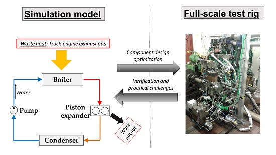
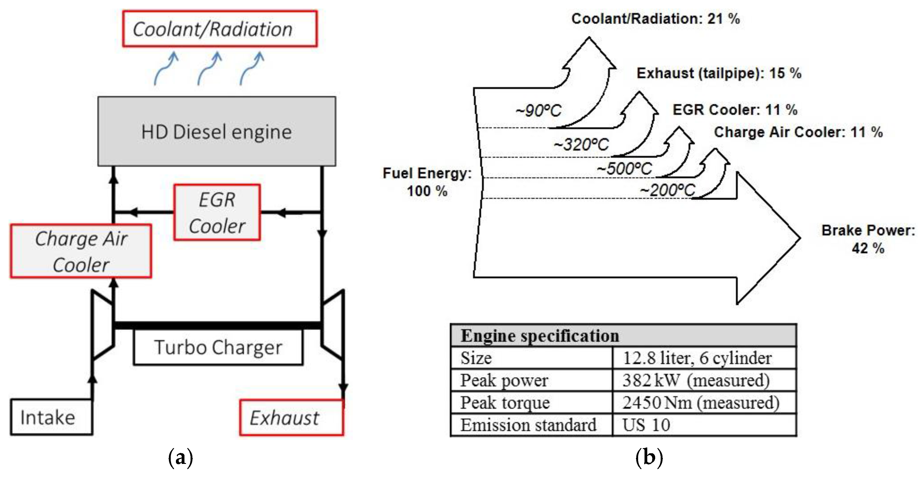
The WHR system examined in this study utilized waste heat from a 12.8-L heavy-duty diesel engine. The schematic engine layout and the possible sources for a WHR system are illustrated in
Figure 1a, supplemented by engine specification data and a Sankey diagram for the fuel distribution in a typical high-load operation point of the engine,
Figure 1b. Exhaust heat and coolant/radiation losses are rejected to the atmosphere, while the charge air and the EGR are cooled down by the engine coolant system (both separated from coolant/radiation in Sankey diagram for visibility). Using charge air or EGR as a source for the WHR system would thus unload the coolant system and avoid additional heat exchangers. Among the available heat sources, the EGR is on the highest temperature level at competitive heat contents, offering thus the highest waste-heat quality. Encouraged by these arguments, the EGR system of the engine was chosen as a sole heat source for the WHR system in this study. The combination of multiple heat sources was not considered to limit complexity of the experimental system.
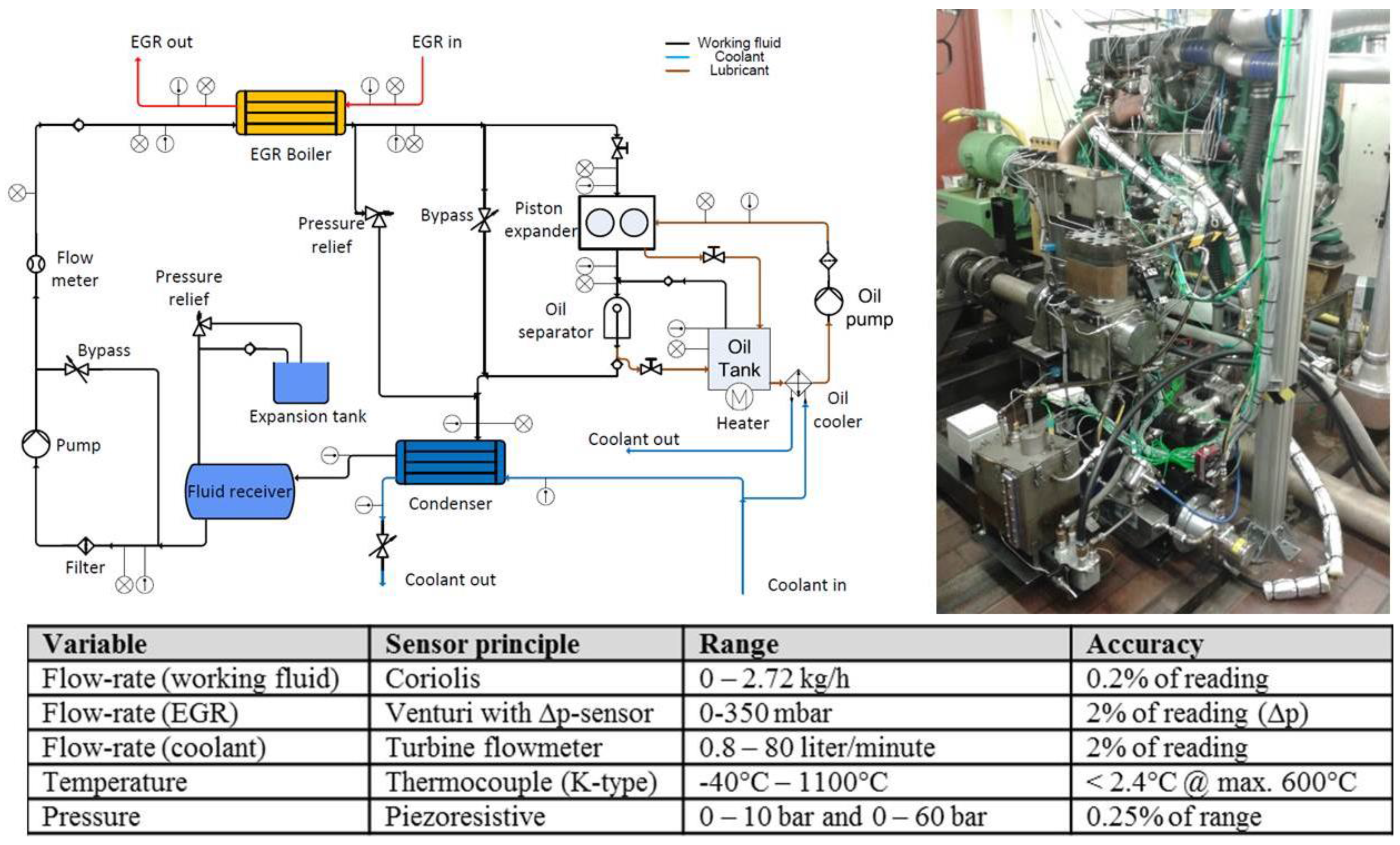
Figure 2 displays the system layout and details of the measurement equipment used to obtain the presented results. The water used as working fluid in the system was deionized to avoid scale forming in the boiler. An observation glass was installed between the boiler and expander in order to check whether the working fluid was fully superheated or still in a two-phase state. The system was developed as a flexible tool for research purposes, neglecting packaging issues related to vehicle design except that the production EGR cooler was replaced with an EGR boiler; this change required minor modifications to the engine’s bracketing.
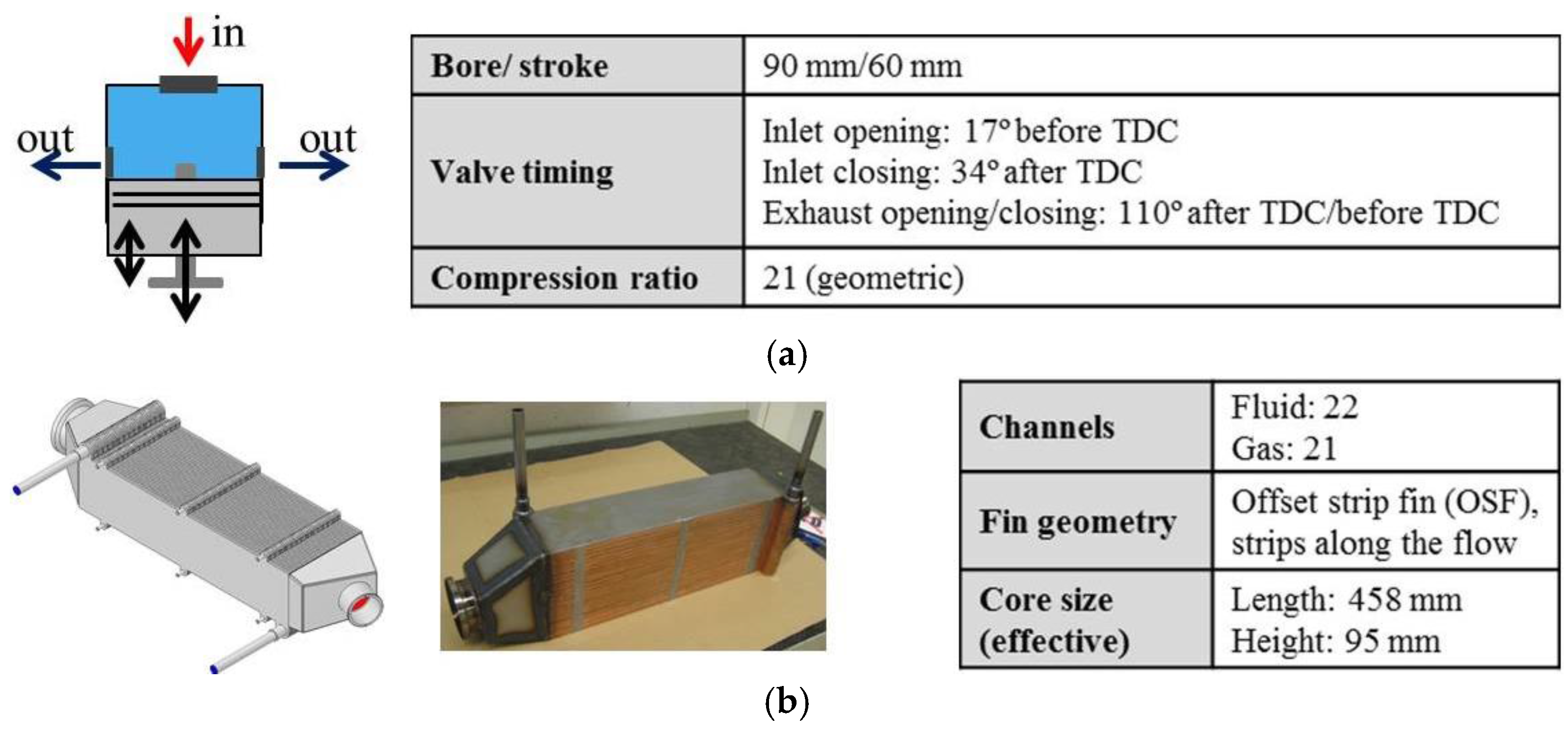
The expansion device used in the heat-recovery system was a two-cylinder uniflow [
13] piston expander in which live steam enters at the top of the cylinder and leaves after expansion through exhaust ports in the cylinder wall near the piston’s bottom dead center position (
Figure 3). The inlet valve of the piston expander is actuated from inside the cylinder by a push-rod, driven by an eccentric cam sitting on top of the con-rod. The steam gets highly re-compressed after the piston closes the exhaust port on its way to top dead center (TDC). This reduces losses at the steam inlet but means that the expander requires a relatively high live steam pressure and a relatively low exhaust steam pressure to produce any power. Preliminary tests with this expander showed that its operation required the live steam pressure to be at least 17 bar if the steam outlet pressure was 1 bar by having the condenser side of the Rankine cycle open to atmospheric conditions. The latter option was selected for the experiments to avoid air infiltration into the cycle. The expander was initially designed for a system that used ethanol as the working fluid and recovered waste heat from multiple sources rather than just the EGR, so it was not expected to be optimal for the experimental setup (which had a maximum pressure of 30 bar because of the EGR boiler’s design). The consequences of this mismatch between the pressure requirements of the boiler and expander were one of the phenomena examined in the study.
A counter-flow plate heat-exchanger was constructed using plate-and-bar technology to operate as an EGR-boiler (evaporator),
Figure 3. The boiler’s height and length were limited by the need to fit into the space once occupied by the engine’s EGR cooler, but there was no such constraint on its width. Vertical plates were used to investigate the effects of gravity and phase separation on the boiler’s operation. The heat exchanger got 43 channels, with one more fluid channel than gas channel in order to capture any flow difference by using infrared (IR) imaging from the side of the heat exchanger. Obviously the outer channel experiences much lower heat input since only a half gas channel supplied heat to this fluid channel, but the interest was to see some gradients due to the vaporization- and flow distribution effects, although the 2 mm thick outer side-plates used were expected to smear some of the IR temperature gradients through axial conduction. The turbulators in the channels are 3.2 mm high, and made of 0.2 mm gauge material. The turbulator geometry is offset strip fin (OSF) with a fin pitch of 1.6 mm and fin length of 3.2 mm and the fin legs oriented along the flow. The separating plates between the channels in the heat exchanger are 0.4 mm thick.
Since this heat exchanger was considered to be a functional prototype for limited testing, no special measures were taken to minimize corrosion. The plates and turbulators were made of stainless steel (SAE 304) and it was copper-brazed (vacuum), which was deemed acceptable for purposes of this study.
2.2. Experiments
To evaluate the potential for recovering heat from the EGR with the boiler, the experimental system was operated with the expander bypassed to avoid oil contamination from its lubrication system, which would otherwise have affected the performance and reproducibility of the boiler tests. In these experiments the expander-bypass valve controlled the boiling pressure. However, tests with the expander engaged were also performed to validate the potential power output with the current expander design and the severity of the oil contamination.
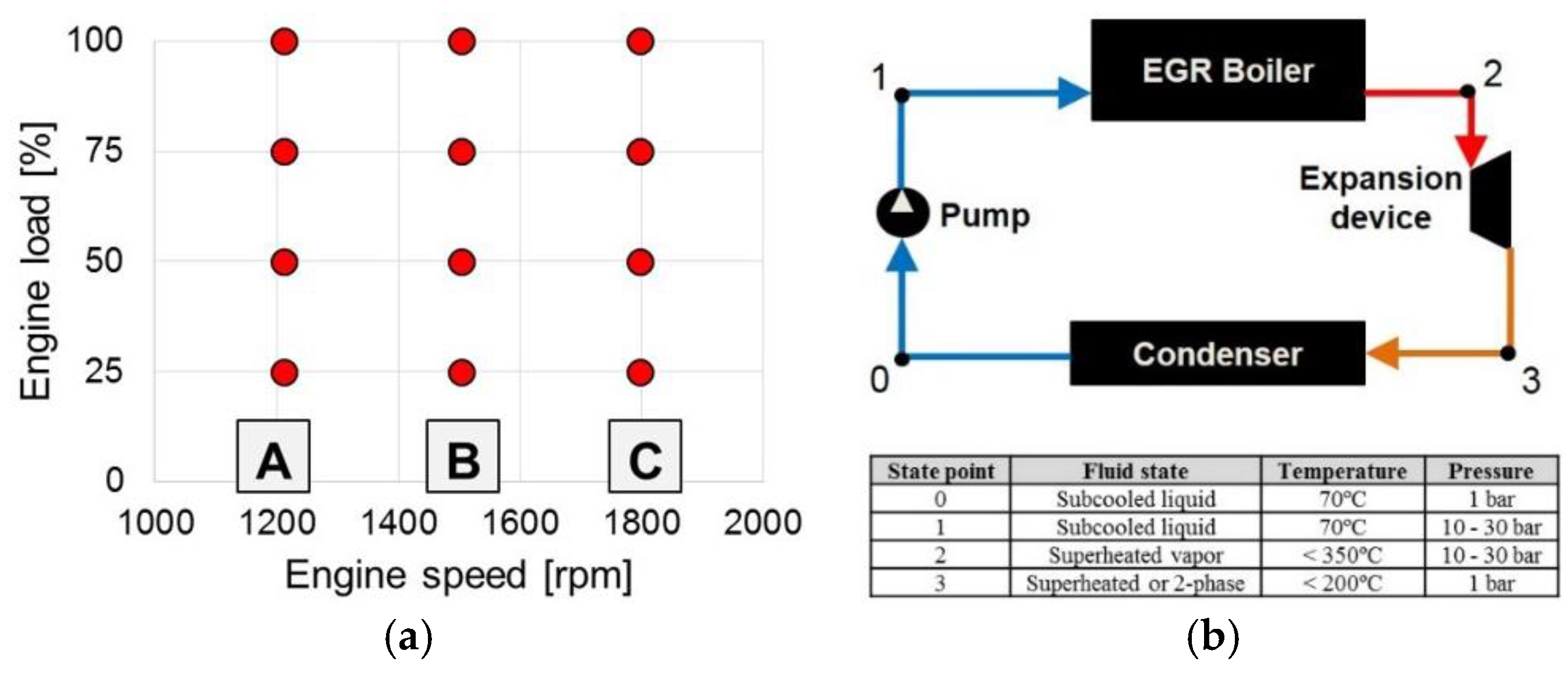
For the experiments presented in this study, the engine was operated in the characteristic points of the European stationary cycle (ESC), which is characterized by three speed and four load levels,
Figure 4a. This allowed reproducible steady-state results for the validation of the theoretical models. The WHR system (
Figure 4b) was operated at atmospheric pressure level on the low pressure side (State Points 0 and 3), while the high pressure side was restricted in peak pressure (30 bar) by the current development stage of the boiler prototype. The fluid temperature for the cold side of the system (State Points 0 and 1) was set to 70 °C, reasoned by a safety margin to the temperature limitation of the filter material and the flow meter. The maximum superheating temperature (State Point 2) was set to 350 °C in order to comply with the specification of the valves and the sight glass mounted between EGR boiler and expansion device.
2.3. Piston Expander and Exhaust Gas Recirculation Boiler Simulations
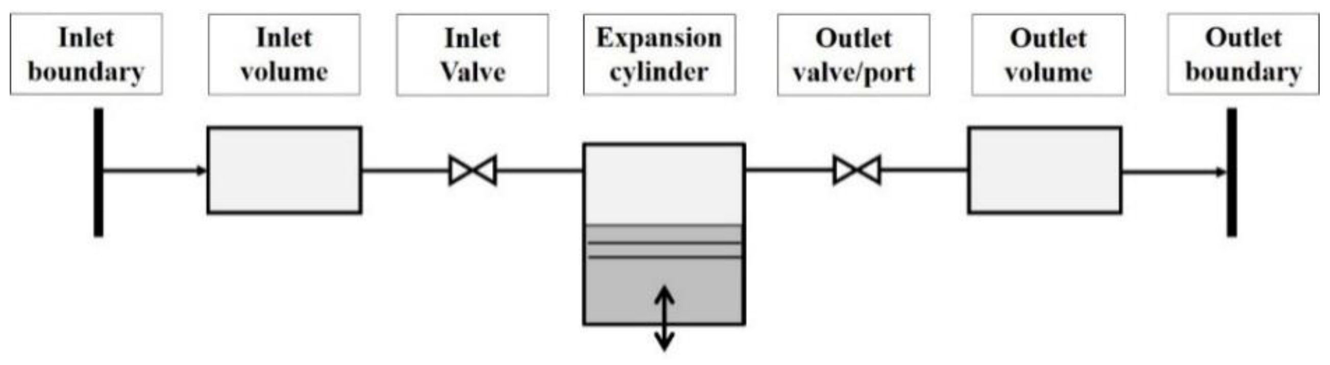
A detailed model of the piston expander was implemented in the commercial one-dimensional (1D) flow simulation package GT-SUITE. The schematic structure of the model can be seen in
Figure 5. At every time step and for each subvolume, the 1D conservation equations for mass, momentum and energy are solved by the software. The geometry data for the expander model were obtained from a physical device that was installed in the test rig. The heat transfer (HT) correlation suggested by Morel and Keribar for internal combustion engines was implemented for in-cylinder HT [
14], while the friction model used was that proposed by Chen and Flynn [
15].
Empirical correlations developed for internal combustion engines were used because they are well documented in the literature and were developed for engines of similar construction to the expander used in this work. The model was utilized to determine optimal operating parameters for the expander and its performance limits when using water as the working fluid in the heat-recovery system.
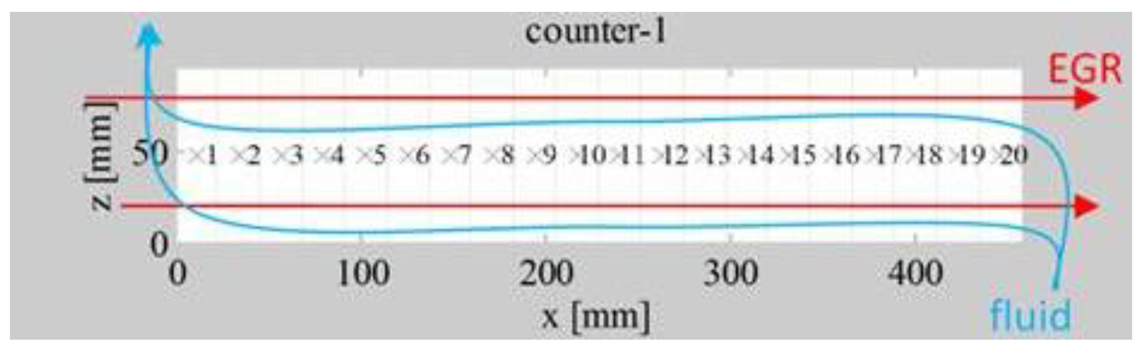
The boiler was sized using a TitanX in-house design tool based on a 0D lumped-element model (LEM) implemented in Matlab
®. The modeled heat exchanger was discretized into 20 elements along the flows (
Figure 6) and all the channels were assumed to be under the same conditions. Discretization into 30 elements was also explored without significant differences in the results. Partial boiling was allowed in elements, and where this occurred the overall HT was iteratively weighted from boiling and single phase enthalpy parts to match the boiling start/end HT energies. Cross-flow at the entry and exits on the fluid side turbulator were ignored in the simulations. Factors and assumptions used are listed in
Table 1.
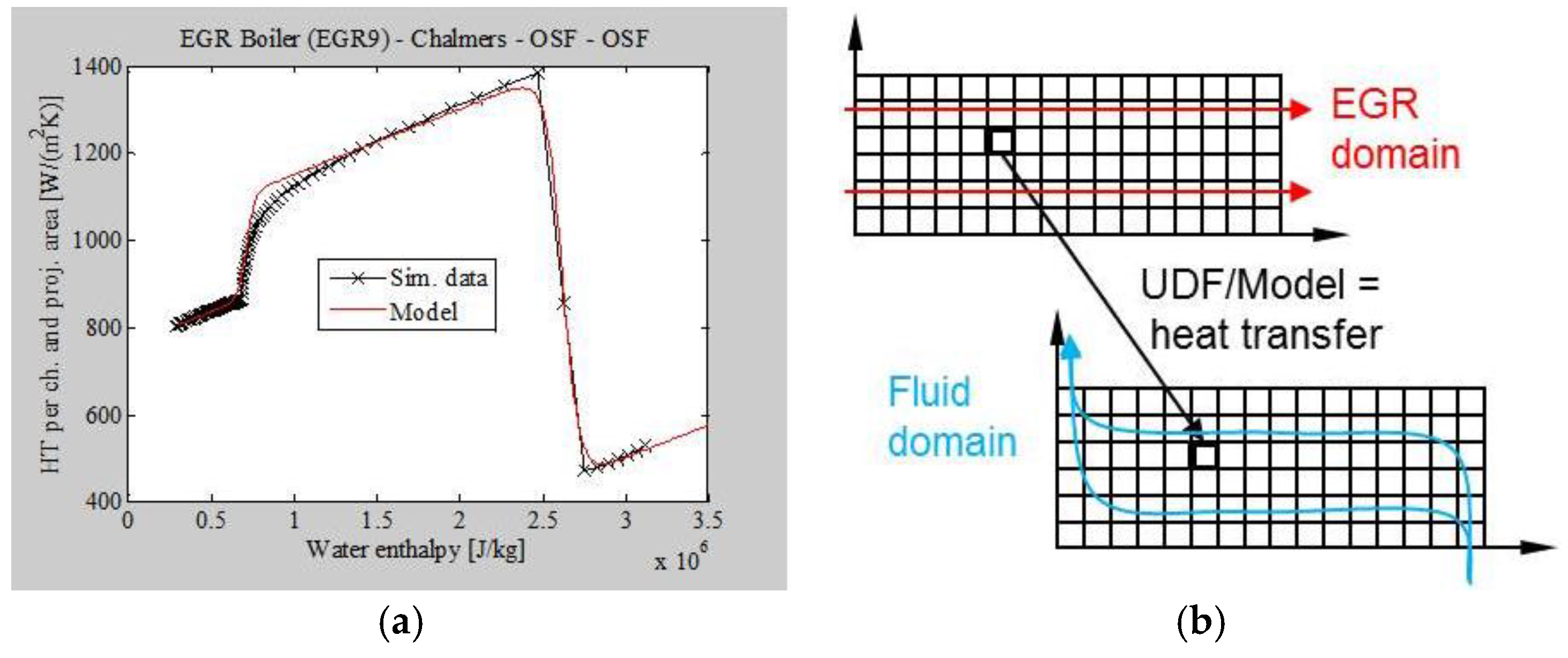
In addition to the LEM, a working computational fluid dynamics (CFD) model was developed in ANSYS Fluent by TitanX to enable (foremost a) qualitative study and characterization of local flow phenomena in fluid channels and (to a lesser extent) prediction of overall heat-exchanger performance. This CFD model, describes a single fluid and a single gas channel as two separate CFD domains. The local projected HT between the two domains is modeled from the LEM simulation described above and implemented as a continuous user-defined function (UDF). Variations in HT strongly depend on the phase on the fluid side, thus the model uses fluid enthalpy as a parameter when computing the projected HT coefficient (
Figure 7). It should be noted that the model is only valid for one particular operating condition and for characterizing the specified HT configuration, so it only provides qualitative results. The CFD model assumes a porous medium when describing the OSF resistance, with differences in resistance along and across the fins (in a separate detailed module). It extends the analytic abilities provided by the LEM by making it possible to investigate how the system is affected by fluid separation, inertia, gravity and variation of the flows in the channels.
The 0D LEM model limitations are that the flow is assumed to flow in a certain idealized way through the heat exchanger, i.e., it is uniform and equally distributed between the channels and over the width of each channel. It cannot deal with phase separation and gravity effects. The HT in the LEM is modelled from HT- and flow area calculations on the channels, fin efficiency model and correlation models for convective HT.
The 2D/3D CFD model on the other hand, with a porous media formulation, avoids a detailed description of the turbulator for saving computational effort. A formulation for the local HT between gas and fluid channels is however required. This was addressed by deriving the HT coefficient based on the LEM results. The local HT over a projected area between the channels (domains in CFD) is then dependent on the fluid and gas temperatures and the HT coefficient. The HT coefficient varies considerably with the fluid phase, so the working fluid enthalpy is used as a single parameter for this model. The HT model is limited to one operating condition and turbulator geometry, i.e., it does not respond to local flow velocities. Thus, the CFD model is not suitable for quantitative performance predictions but it provides a qualitative picture of the flow, phase separation and gravitation effects. It can be used as a tool for investigating the internal flow of a proposed heat exchanger.
3. Results
This section presents findings from experiments with the system described above and complementary simulations of the piston expander and EGR boiler.
3.1. Efficiency Terminology
The results presented in the following paragraphs partly rely on the evaluation of the thermal efficiency for the WHR system as well as the isentropic and the overall expander efficiency. For clarification of the terminology, the applied efficiencies are defined within this paragraph.
The thermal system efficiency η
th in Equation (1) relates the shaft work output of the expander
wexp,shaft to the heat
qEGR,in, which supplied to the WHR system by the EGR line. It quantifies how well the WHR system transforms the supplied heat to mechanical work output and depends mainly on expander, working fluid and EGR boiler performance under specific cycle operating conditions:
The isentropic expander efficiency η
is in Equation (2) describes the actual expansion work
wexp done by the fluid on the piston in relation to the theoretical maximum work
wexp,is done by the fluid in an isentropic expansion. Kinetic and potential energy effects were neglected, so
wexp,is can directly be expressed as the isentropic enthalpy drop ∆
his of the fluid:
For the overall expander efficiency η
o in Equation (3), the actual expander shaft work
wexp,shaft is related to the isentropic enthalpy drop ∆
his. The mechanical losses of the expander are included in this efficiency. Since the shaft work could be measured during the experiments, the overall expander efficiency was applied for the evaluation of the experimental results:
3.2. Experiments with the Bypassed System at European Stationary Cycle Points
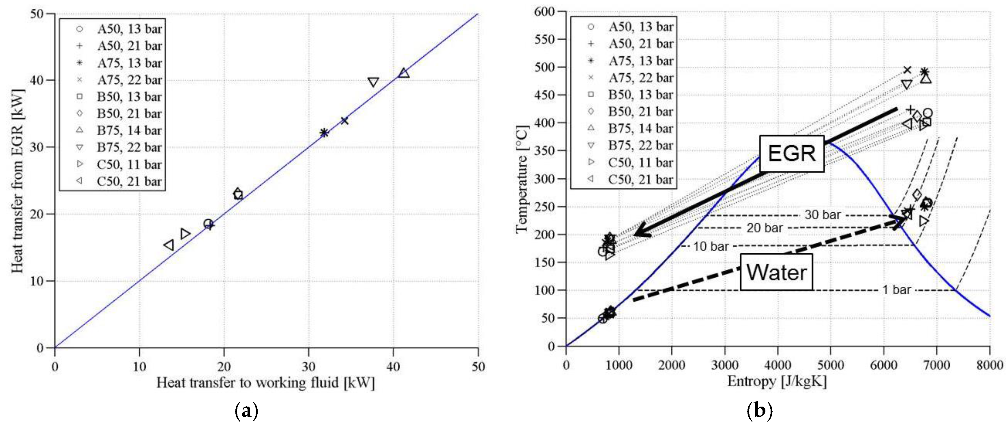
The performance of the heat recovery system, in terms of HT from the EGR and EGR cooling capability is shown in
Figure 8. Superheating clearly occurred at all covered ESC points and considered boiling pressures. The 25% load cases are excluded since it was not possible to achieve stable superheating at these points due to low EGR temperatures and flows. At the time of the boiler tests, the engine could not be operated at full load with the applied setup because of the limitations of its dynamometer. Thus, the ESC operating points A100, B100, C75 and C100 are not included in the
Section 3.2 and
Section 3.3 of this publication. As first reported by Panesar et al. [
6] on the basis of a theoretical study, water-based working fluids have higher boiling temperatures and heats of evaporation than organic fluids, which limits their ability to cool the EGR. Consequently, the EGR temperatures observed during the experiments at the higher load points and boiling pressures were around 200 °C, or more than double the values (in °C) maintained with the production EGR cooler. This necessitated some modification of the setup that will be discussed as follows.
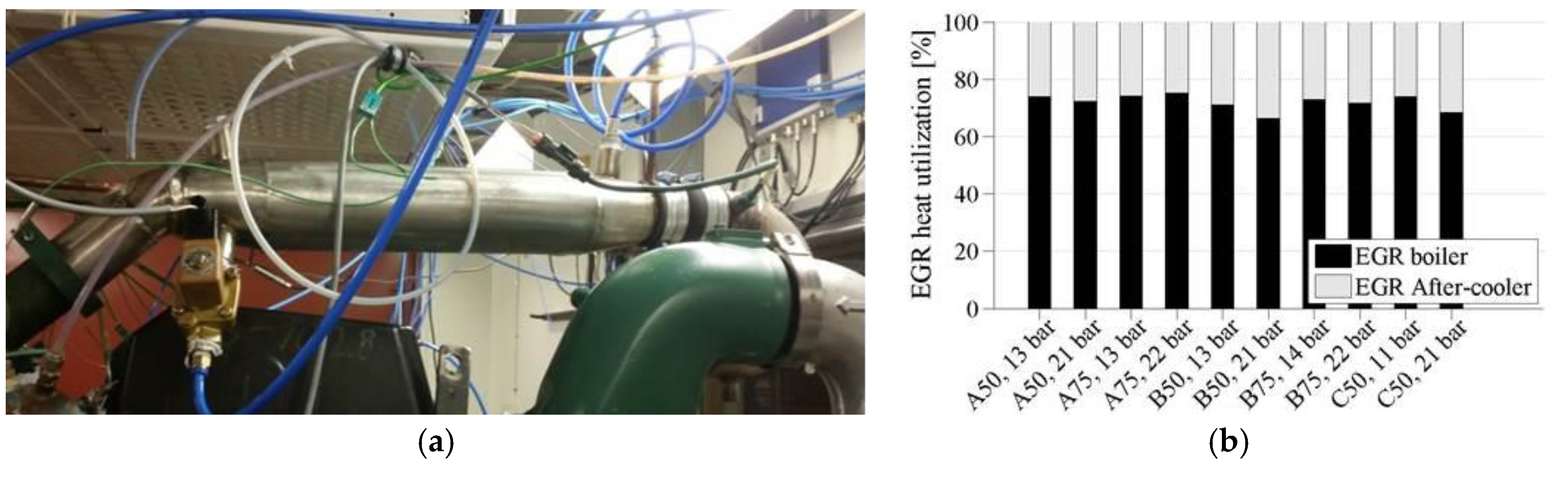
To overcome the EGR temperature problem, an EGR after-cooler was designed that was intended to provide sufficient cooling and have minimal impact on the design of the EGR system (thus avoiding flow restrictions and any need for additional piping and brackets). The designed after-cooler replaced a horizontal section of the EGR route just before the EGR mixes with the charge air, and consists of a jacketed stainless steel pipe of identical diameter to the EGR pipe, supplemented with an internal helical copper coil. The jacket is cooled in a parallel-flow configuration to the EGR, with the outlet water streaming through the copper coil in counter-flow to the EGR. This system provided stable EGR temperatures below 80 °C at all considered operating points. The after-cooler mounted in the EGR route and the distribution of EGR heat between the boiler and after-cooler are shown in
Figure 9. Up to a third of the EGR heat was transferred to the after-cooler. The impact of the boiling pressure on this fraction is rather weak and less systematic than expected. However, at operating points with lower EGR temperatures (e.g., B50 and C50), high boiling pressures reduced the boiler’s heat utilization due to the pinch-point limitation.
3.3. Experiments with the Expander Engaged
Following the tests with the bypassed system, the operation and performance of the current expander design was evaluated.
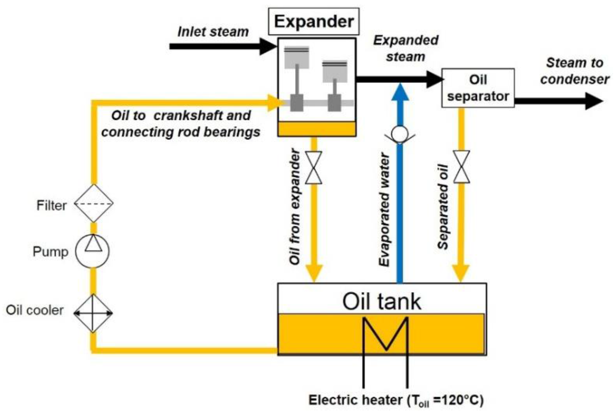
An engine oil with SAE classification 15W40 was used for these initial tests. The expander’s oil circuit was based on a dry sump system, in which the external oil tank was electrically heated to 120 °C to evaporate blow-by water from the lubrication system quickly and return the steam to the system downstream of the expander as illustrated in
Figure 10. The oil from the tank was cooled to protect the pump and to increase the viscosity before being supplied via the crankshaft to the connecting rod bearings. The cylinder liners of the expander were not lubricated. Downstream of the expander, an oil separator was installed for removing excessive lubricant from the working fluid in case of contamination inside the expander or from oil droplets transported in the evaporated water from the oil tank.
During expander operation, perceptible contamination of the working fluid with oil and vice versa was observed due to blow-by, resulting in unacceptable reductions in the oil’s viscosity and hence the expander’s oil pressure, which had adverse effects on the lubrication of the expander’s bearings. The water separation capability of the 15W40 engine oil was poor and evaporation of the working fluid from the oil in the tank was too inefficient to address these problems. Consequently, the oil was replaced with steam engine oil that had a kinematic viscosity of 290 mm²/s at 40 °C (DIN 51562-1) and which showed improved properties (specifically, viscosity and ease of separation) in the presence of water.
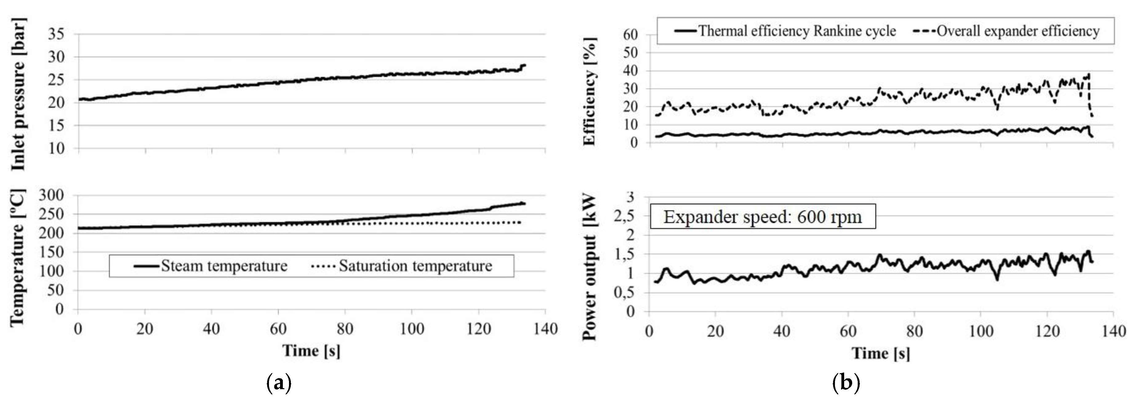
Figure 11 shows the steam boundary conditions and performance of the expander during a test in which the load was increased from B50 (with saturated vapor) towards B75 (with superheated vapor) to determine how the heat recovery system’s thermal efficiency and expander power output responded to the increased heat input and the concomitant increase in steam pressure. The expander speed was maintained at 600 rpm during the test; further speed increases had no positive effect on power output. To assess the Rankine cycle’s thermal efficiency, the power output is related to the heat transferred in the boiler, while the expander’s overall efficiency is assessed in terms of the isentropic enthalpy drop of the fluid over the expander. A general conclusion from this test is that the thermal efficiency achieved (between 5% and 10%) is rather poor compared to the highest values reported in similar studies, as summarized for instance by Sprouse and Depcik [
1]. This is because the expander used in the tests does not perform well in the tested configuration under the given boundary conditions. Increasing the inlet steam pressure from 20 bar to 27 bar doubled both the expander and thermal efficiencies, indicating that the optimum inlet pressure for the expander is above 27 bar. At lower inlet pressures, the expander is suffering from over-expansion, implying that the design pressure ratio of the device is larger than the operating pressure ratio. Over-expansion mode causes a sharper decrease of the expander efficiency compared to under-expansion due to the neagtive work done by the piston, so this operating condition should be avoided. The consequences of over- and under-expansion on reciprocating expander efficiencies were examined in detail by Kim et al. [
19].
It is possible that the system’s thermal efficiency could have been increased further by raising the expander’s inlet pressure above 30 bar, but this was considered inadvisable at such an early stage in the testing of the EGR boiler prototype. Lowering the condensation-side pressure below atmospheric level was not attempted due to the risk of problematic air infiltration into the system. The remaining option was to modify the expander’s design by extending the steam admission phase or reducing the geometrical compression-ratio. These concepts, which both represent general solutions for adapting a uniflow expander to specific inlet pressure limitations, are discussed in
Section 3.4.
3.4. Expander Simulations (GT-SUITE)
The effects of varying several parameters were investigated using the GT-SUITE piston expander model. A particular objective was to assess potential strategies for improving the performance of a uniflow expander when the admission pressure is limited (or equivalently, for maintaining performance at a reduced admission pressure). One way of doing this is to reduce the expander’s compression ratio and hence the re-compression pressure (thereby reducing the pressure required for efficient expander operation).
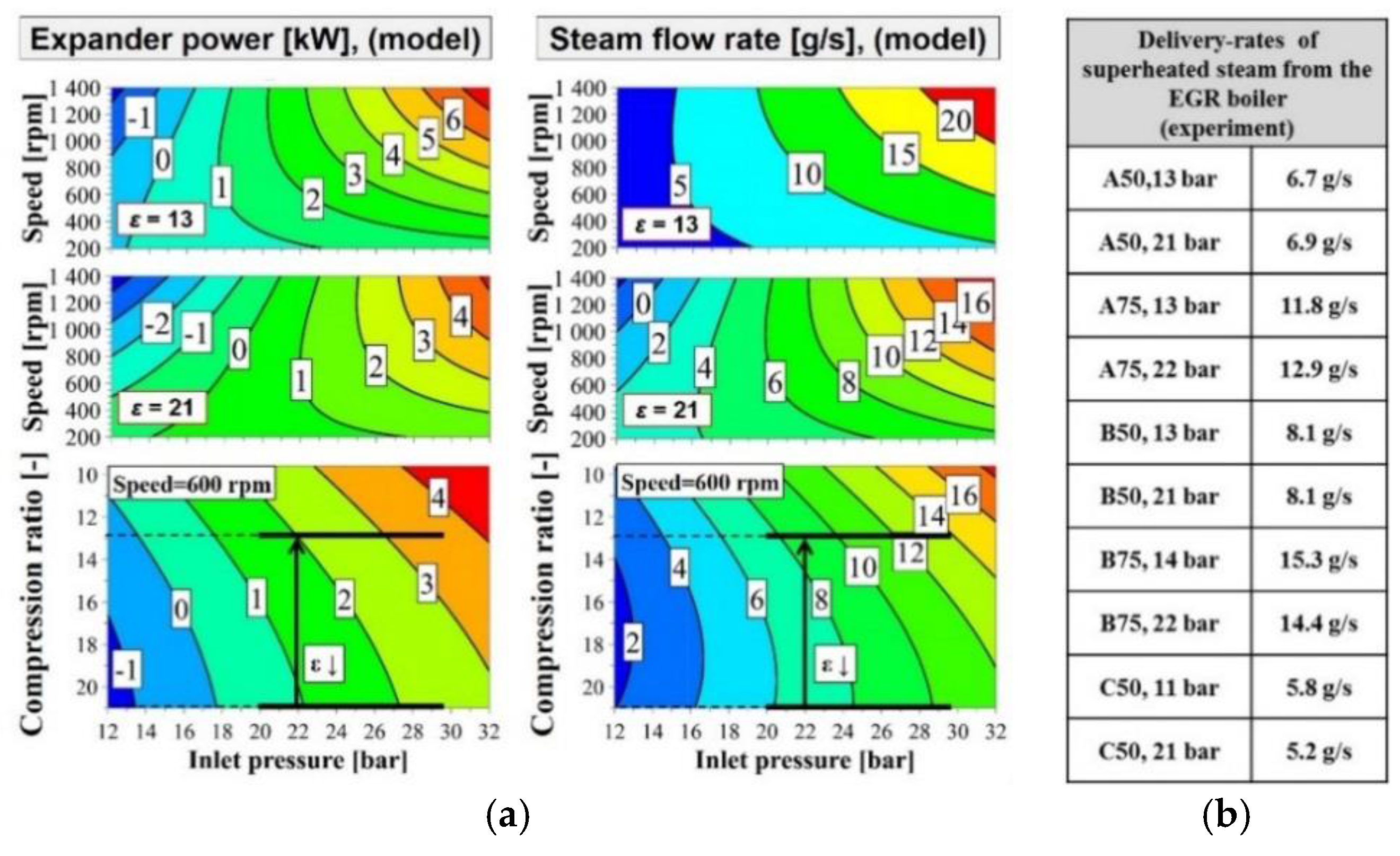
The modeled dependence of the expander power output, and associated steam consumption, on the steam inlet pressure, compression ratio and expander speed are mapped in
Figure 12. The calculated flow rates include the blow-by losses from the expansion cylinder, which were modeled by introducing a bypass line to the cylinders containing an orifice with a constant diameter of 1.2 mm. This modification provided a good match with the experimental steam-flow rate through the device and the observed levels of blow-by condensate. For comparative purposes,
Figure 12 also shows the steam flow rates the boiler can supply at stable superheating levels, which were determined using the results of the EGR boiler tests discussed in
Section 3.2. By projecting the 20–27 bar inlet pressure (at 600 rpm) for the experimental operating point characterized in
Figure 11 onto these maps, it can be seen that the expander model confirms a power output of 1–2 kW for the baseline compression ratio of 21. From the speed variation in the expander maps, it can be seen that increasing the expander speed beyond 600 rpm gives no improvement in power output at this compression ratio since the low inlet pressure is the power-limiting factor. For the same reason, the steam flow rate measured during the expander test described in
Section 3.3 did not exceed 6–8 g/s, causing the superheating temperature to increase over time (
Figure 11).
The results presented in
Figure 12 also indicate that reducing the compression ratio from 21 in the current design to 13 would permit the expander to be operated at a lower steam inlet pressure, with power outputs of up to 3.5 kW being achievable (at 600 rpm) with an inlet pressure of 30 bar. A consequence of the increased dead volume would be a 40% increase in steam consumption at this operating point, which should not present a problem given the measured steam delivery rates of the boiler. One major conclusion that can be drawn by comparing the plots showing the expander power as a function of the inlet pressure and expander speed at compression ratios of 21 and 13 is that reducing the compression ratio cannot be expected to increase the expander power output at the boiler’s maximum steam delivery rate of around 10–15 g/s. However, it should be possible to maintain a given expander power output while reducing the expander’s speed (and thus the impact of friction) and also reducing the live steam pressure by up to 30%. These findings clearly confirm how sensitive the performance of a piston expander is to both its design and the applied system pressures, as it was previously concluded by other groups in the field [
19,
20].
From the measured steam delivery rates of the boiler it can be seen that the steam flow rate has only a very weak dependency on the boiling pressure. While the pinch point limitation in the boiler lowers the utilizable EGR temperature difference at high boiling pressures, the heat of vaporization for water is up to 20% lower under these conditions (explaining why the overall flow rates can be maintained).
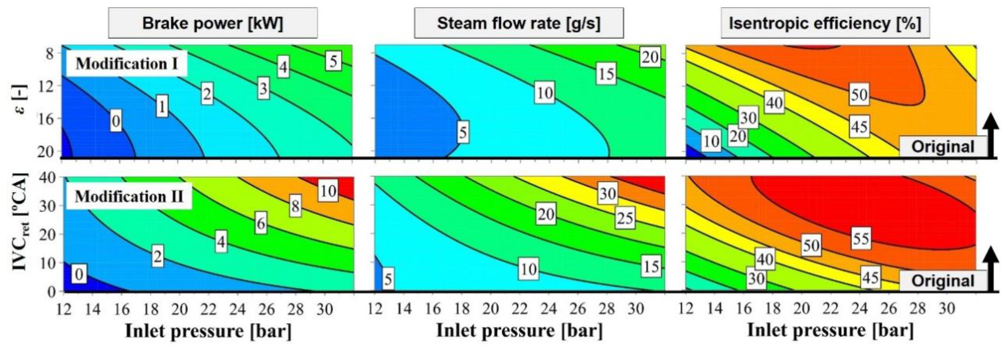
Another alternative to a reduced compression ratio (Modification I,
Figure 13) is to extend the admission phase by closing the inlet valve later in the expansion stroke (Modification II,
Figure 13), thus allowing more steam to enter the cylinder. None of the modifications clearly offered better performance than the others with respect to the simulated expander brake power and steam flow, particularly given that the current system configuration cannot deliver steam flows above roughly 15 g/s. All of the modifications allowed the brake-power (2–4 kW) to be maintained while reducing the steam admission pressure. In both cases, the vapour at the inlet was assumed to be superheated (40 °C above saturation temperature), the outlet pressure was atmospheric, and the expander speed was constant at 600 rpm.
The simulated modifications (I, II) increased the isentropic efficiency within the displayed inlet pressure range:
The sensitivity of the isentropic expander efficiency to these modifications declined with increasing inlet pressure. At pressures above 30 bar, the modifications started reducing efficiency because the losses they induced outweighed the increased power output.
3.5. Impact of the Modified Expander Compression Ratio (Experiments)
The predicted benefit of reducing the expander’s compression ratio under a given set of boundary conditions required experimental confirmation. In practice, this was achieved by mounting a distance plate between the cylinder housing and the expander’s crankcase to increase the dead cylinder volume at piston TDC and thus reduce the compression ratio. The inlet valve event (lift and phase) remained unchanged, but the opening period of the outlet port increased slightly. To ensure reproducible heat input into the Rankine cycle test rig, the engine was operated in a steady state at the B100 ESC operating point in these experiments. Compared to the results presented in previous paragraphs, an update of the dynamometer allowed to increase engine load conditions to full load level (A100, B100 and C100). The B100 operating point guaranteed the highest EGR temperatures (500–530 °C), although the EGR flow rate was somewhat lower than that achieved at the B75 operating point. The mass flow rate in the Rankine system under these conditions was around 10 g/s but varied slightly with the EGR temperature. Analysis of the results suggested that the resulting variation in the cycle pressure had no reproducible impact on the heat utilization or the Rankine flow rate at these high EGR inlet temperatures. The EGR outlet temperatures from the boiler at this operating point were as high as 250 °C.
The measurements presented in this section were taken after the expander inlet steam conditions (temperature and pressure) and the expander’s brake power output reached steady state, so that a representative measurement sample over several minutes could be taken. Each experimental data point in
Figure 14,
Figure 15 and
Figure 16 represents the mean value of such a steady state measurement sample.
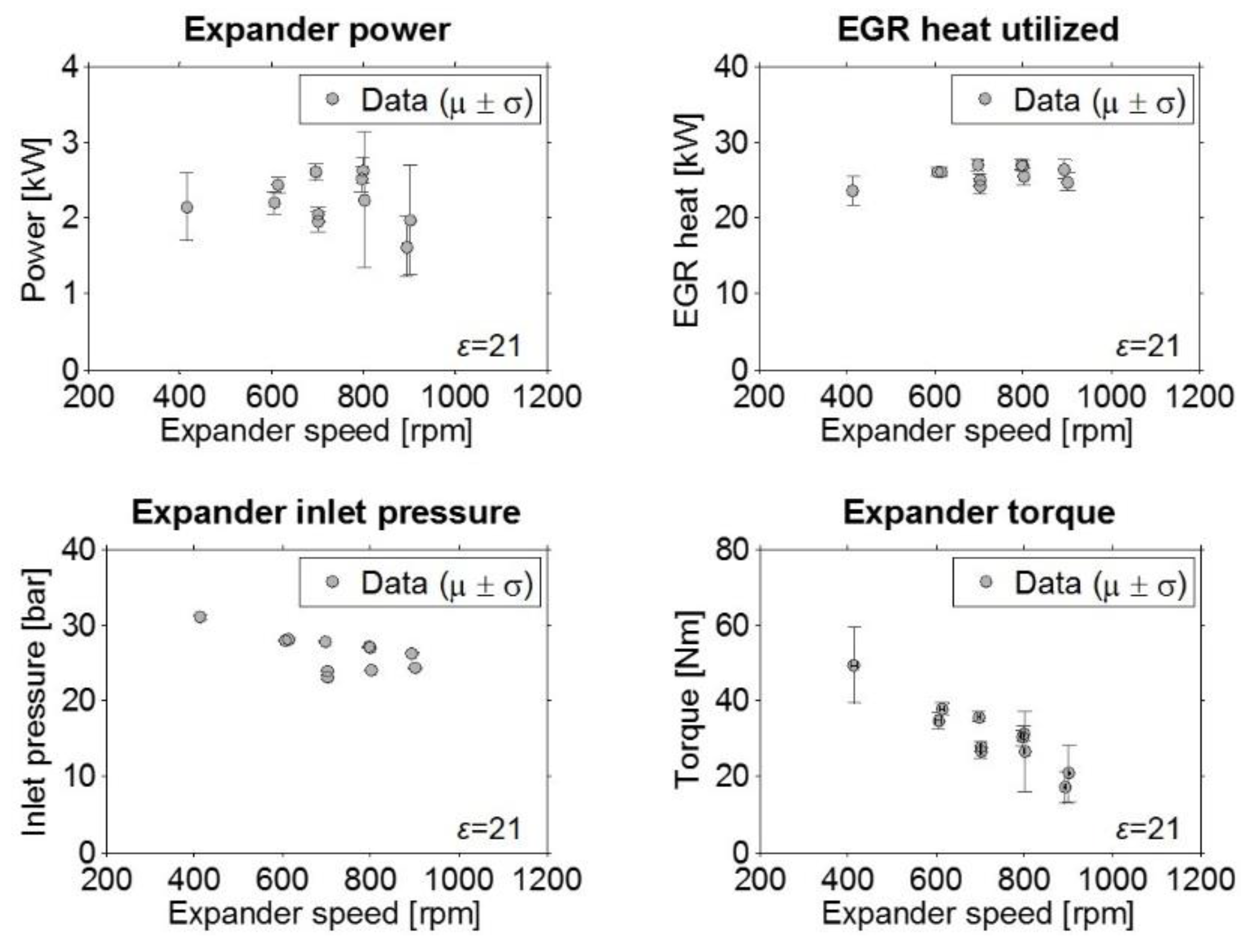
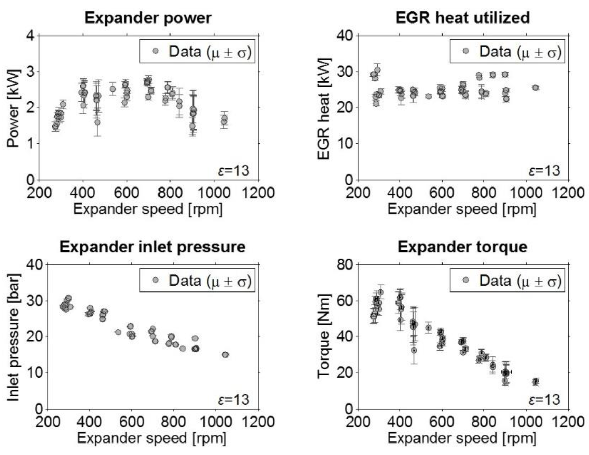
Figure 14 shows the expander performance and boundary conditions for the baseline compression ratio (ε = 21) as a function of the expander shaft speed. The expander brake was not designed to operate at less than 500 rpm and showed control instabilities at speeds of 400–500 rpm, causing considerable variation in the expander’s power output within this range. The maximum power output in this configuration was around 2.7 kW and could be generated at speeds of 700–800 rpm. At speeds above 800 rpm, the power output dropped again and the standard deviations of the measured variables started to increase, indicating that the system was approaching the expander’s stable operation limit under the tested inlet conditions.
Figure 15 presents the corresponding experimental results for the expander operating at the lower compression ratio of 13. Under these conditions, the expander power output could be maintained while reducing the inlet pressure by around 30% relative to that required at the baseline compression ratio, confirming the predictions made on the basis of the simulations (
Section 3.4). This occurred because the lower compression ratio reduced the degree of re-compression of the steam in the expansion cylinder, allowing the expander to maintain stable operation with a live steam pressure of around 15 bar at the investigated Rankine cycle operating point. The expander’s operating range was thus extended to better match the specifications of the system’s other components, allowing its peak power output to be achieved at speeds of around 400 rpm. Reducing the Rankine cycle pressure was also beneficial because it reduced the pump power, although in absolute terms the pump power was negligible under all tested conditions (<100 W at all operating points) compared to the expander power output. This is one advantage of using water as the working fluid: the mass flow rates required in a water-based Rankine cycle are far lower than those required when using organic working fluids [
22].
3.6. GT-SUITE Expander Model versus Experimental Results
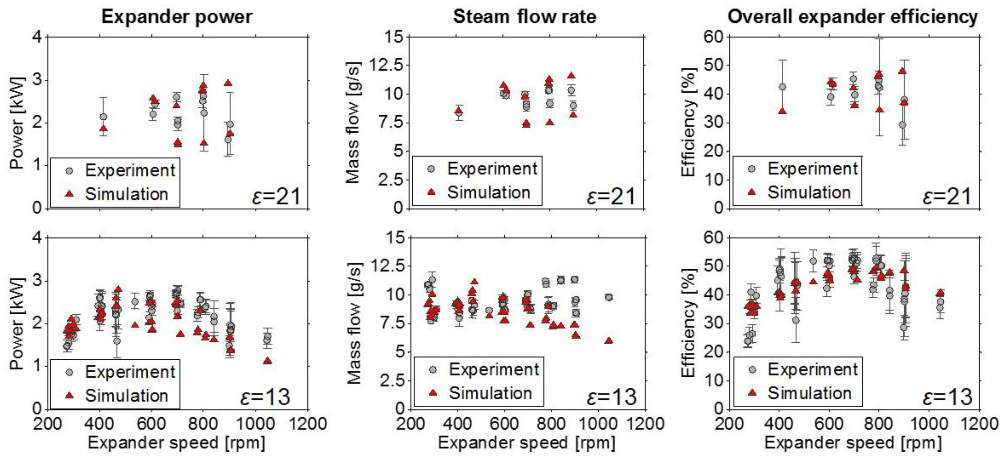
The predicted (based on the GT-SUITE simulations) and experimentally observed expander power values, steam flow rates (including blow-by) and overall efficiencies for expander compression ratios of 21 and 13 are compared in
Figure 16. The overall expander efficiency peaked at values of 50%, which is on the lower end compared to the results presented by other researchers [
19,
20,
21]. Beside the non-optimal expander design, one reason for a lower efficiency might be that the results in this study describe the overall expander efficiency, which includes the mechanical losses.
It is clear that there is a good qualitative match between the experimental data and the simulations, although there exist obvious quantitative deviations in some of the compared operating points.
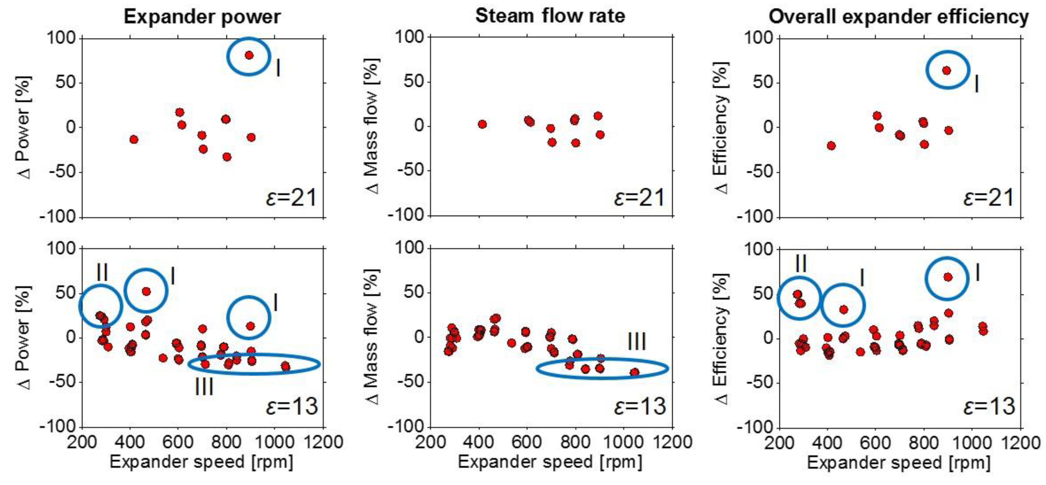
To obtain a clearer picture of the quantitative differences, the relative deviation of the simulation compared to the experiments was computed according to Equation (4):
The model deviation is shown in
Figure 17. In some operating points, there is a deviation of close to 50% or even more between simulation and experimental results. By reviewing the experimental data and boundary conditions, three main causes could be derived for these extreme outliers (marked in
Figure 17):
The stability issues of the expander break at speeds around 400 rpm and the stable operation limit of the expander at speeds higher than 900 rpm caused high standard deviations for the measured expander power output (
Figure 16). This weakens the reliability of the experimental results in these operating ranges. Despite the poor match with the mean value of these test runs, the simulation results are for nearly all cases within the standard deviation of the measured data as it can be seen in
Figure 16;
The highlighted outliers were caused by non-reproducible deviations in expander power output within a particular measurement campaign. The reason for this drop in expander power output could not be discovered. The experimental data samples were acquired within several independent measurement campaigns, interrupted by necessary maintenance and repairs of the expander and the WHR system. Despite all the care taken, these actions could have affected the performance of the experimental setup by e.g., steam leakages of a not properly sealing expander head gasket;
At higher expander speed, the impact of throttling losses caused by the steam inlet system (valves and ports) becomes increasingly important for the actual flow rate and power output of the expander [
13]. Lacking the possibility for flow testing of the expander intake system, constant valve discharge coefficients were implemented into the model. From literature it is known, that geometry as well as lift and pressure ratio across the valve affect the actual discharge coefficient [
23,
24]. This dependency was not considered in the model.
It can be concluded that I and II were mainly caused by some unsatisfactory measurement campaigns, while III was an obvious limitation of the modelling approach.
Further reasons for the scattering of the data in
Figure 17 could be inadequate prediction by the model of in-cylinder heat losses and expander friction, which were estimated using empirical models developed for internal combustion engines. This approach was chosen since comparable models for steam expanders are lacking in literature. More work in this matter is highly encouraged for the future. The friction model was calibrated against test data for the expander but it does not consider factors such as the dilution of the lubrication oil with water (which causes a gradual reduction in oil viscosity) and the resulting reduction in friction torque during protracted expander operation. Similarly, the HT correlation does not account for the way that condensation at the cylinder walls increases the corresponding HT coefficients. To minimize condensation and thus the impact of this error, the expander was operated with the superheated vapor until thermocouples on its outer surface indicated a stable temperature, implying that the walls were warmed up. Only then, the measurement samples were acquired.
Despite the quantitative deviations in some operating areas, the presented expander modelling approach was with low calibration effort capable of predicting design modifications that led to an improved expander performance at the test rig. This achievement was the initial motivation for including the expander model in this study. For further refinement and calibration of the model for this particular expansion device, a flow test and in-cylinder pressure measurement would have been required.
3.7. Exhaust Gas Recirculation Boiler Simulations
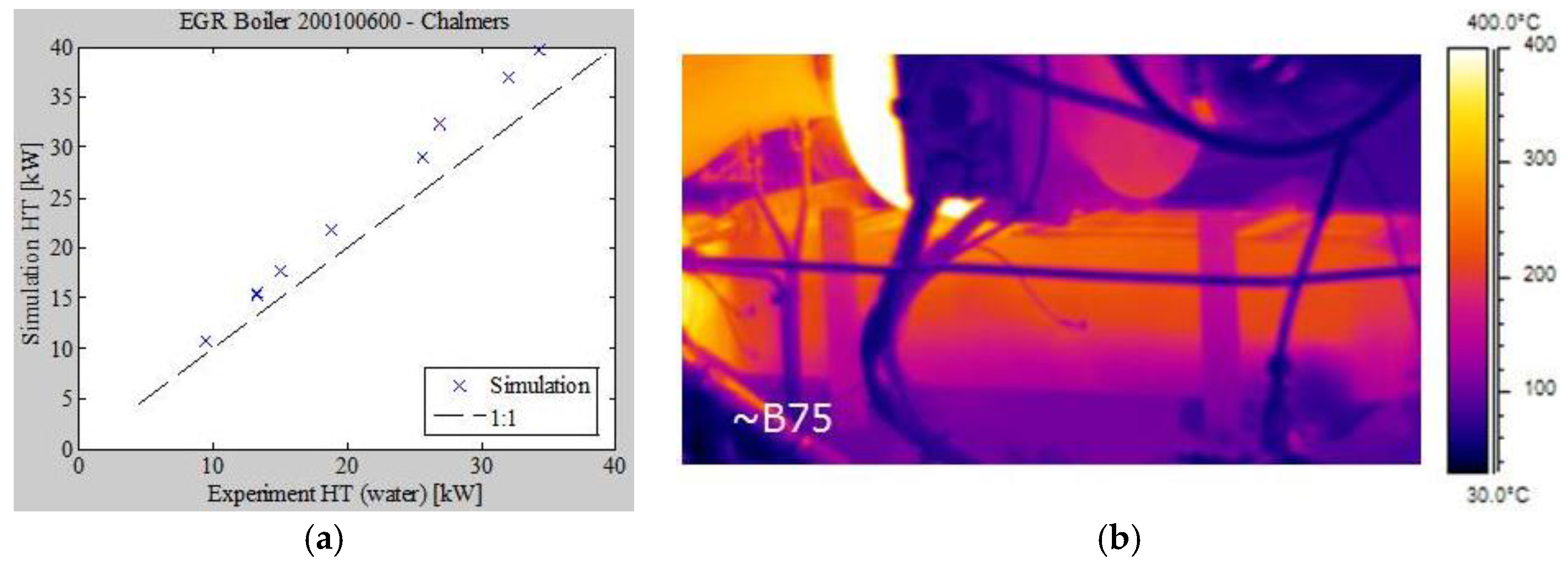
Comparison of the LEM simulation and experimental data (
Figure 18) reveals that the simulation over-predicts superheating in most cases. There may be many reasons for this, e.g., two-phase phenomena (model limitations in handling gravity or fluid separation, for instance), inaccuracies in the model’s coefficients and correlations (relating to fluids and geometric factors), other model limitations (e.g., channel-to-channel variation), fouling (which the model ignores completely), and heat losses to the surroundings.
Two-phase phenomena and the characteristics of the EGR boiler were also explored by means of CFD simulations. The details of these investigations are beyond the scope of this article, but the simulations revealed clear internal circulation on the fluid side: most of the liquid fluid immediately turns and flows along the bottom of the heat-exchanger. Along the way, it gradually evaporates and expands into the center region. However, some of the vapor turns and flows in the reverse direction, creating a large steam “bubble” over the channel section that reduces both the effective HT area and temperature difference, thereby reducing the overall heat-exchanger efficiency. This is likely the main reason for the difference between the LEM predictions and the experimental data. It should be noted here that the engine (and hence the boiler too) are mounted in the same fashion in the test rig as in the truck, at a 4° angle to the horizontal plane, which helps to drive the liquid forwards in the bottom of the vertical channels. Infrared images of the side-plate (
Figure 18) support the CFD predictions, indicating that temperatures are significantly lower at the bottom of the heat-exchanger. The outer channel on the boiler is a fluid channel but the thick side-plate smears the observable gradients due to axial conduction in the wall. Despite this smearing, the images clearly show that the liquid phase is not distributed uniformly across the boiler’s height.
4. Conclusions
The goal of this study was to identify and characterize design component-level challenges associated with using a Rankine cycle-based system to recover waste heat from the EGR of a heavy-duty diesel engine. This was done by closely coupling experiments conducted on a full-scale demonstrator test bench system with simulations of processes in the EGR boiler and piston expander to highlight parameters and features that strongly influence the system’s overall performance. Water was used as the working fluid because of its promising efficiency and convenience for applications at the considered heat-source temperatures.
The system’s EGR boiler was designed as a plate-heat exchanger with vertical plates in order to investigate gravity effects in the boiler. CFD simulations and infrared images taken during the experiments revealed the presence of internal flow circulation in the boiler. A steam “bubble” was formed and shown to reside in the upper part of the boiler, reducing the area of effective HT to the working fluid. The cooled EGR temperatures after the boiler were high, exceeding 200 °C in many cases; this is more than twice the temperature (in degrees Celsius) achieved with the engine’s standard EGR cooler. A new EGR after-cooler that further cooled the EGR to 80 °C was therefore built and mounted in the EGR route.
The system’s thermal efficiency peaked at just below 10% because of problems with the heat utilization in the boiler and the piston expander, which was not designed for use at the tested boundary conditions. A major bottleneck was the high re-compression of exhaust steam due to the expander’s uniflow mode of operation, which made it necessary to use boiling pressures of at least 25 bar to achieve a stable expander power output. These pressures were close to the maximum allowable pressure (30 bar) for the prototype EGR boiler. A 1D simulation model of the expander indicated that either reducing the compression ratio or extending the steam admission phase could allow similar expander power outputs to be achieved while reducing the admission pressure by up to 30%. Experimental results confirmed the model’s predictions: reducing the compression ratio made it possible to improve the device’s operating stability at the steam delivery rates that the boiler was able to provide. This result underlines the importance of careful component customization when attempting to create an effective heat recovery system.


 ,
, 


