Article

Sliding Mode Variable Structure Control of a Bearingless Induction Motor Based on a Novel Reaching Law

1
School of Electrical and Information Engineering, Jiangsu University, Zhenjiang 212013, China
2
Automotive Engineering Research Institute, Jiangsu University, Zhenjiang 212013, China
*
Author to whom correspondence should be addressed.
Energies 2016, 9(6), 452; https://doi.org/10.3390/en9060452
Submission received: 12 April 2016 / Revised: 26 May 2016 / Accepted: 27 May 2016 / Published: 13 June 2016

Abstract

:
In order to improve the performance of the Bearingless Induction Motor (BIM) under large disturbances (such as parameter variations and load disturbances), an adaptive variable-rated sliding mode controller (ASMC) is designed to obtain better performance of the speed regulation system. Firstly, the L 1 norm of state variables is applied to the conventional exponential reaching law and an adaptive variable-rated exponential reaching law is proposed to reduce system chattering and improve bad convergence performance of the sliding mode variable structure. Secondly, an integral sliding-mode hyper plane is produced according to the speed error in speed regulation system of BIM. Current signal is extracted by the combination of the sliding-mode hyper plane, the electromagnetic torque and the equation of motion. Finally, the feedback speed can adjust operating state adaptively according to speed error and make system chattering-free moving. The simulation and experiment results show that the proposed ASMC can not only enhance the robustness of the system’s uncertainties, but also improve the dynamic performance and suppress system chattering.

1. Introduction

The Bearingless Induction Motor (BIM) integrates motor rotation and suspended function. It has a series of better characteristics than the conventional motor, such as no friction, no loss, no lubrication, longer service life, high speed and high precision running. BIM holds an irreplaceable status in some special fields including high speed electric spindles, high speed gyros, fly wheel energy storage and aerospace, etc. [1,2,3,4,5]. However, BIM is a multivariable, nonlinear, strongly coupled and complex system. When it experiences motor parameter variations or external large disturbances, BIM can not achieve high precision control performance under the conventional Proportional-Integral (PI) controller [6]. As a consequence, it is extremely important to design a fast, accurate and stable high-performance controller.
At present, many relative scholars around the world have done a great deal of research, and some advanced control strategies have been gradually applied to the motor system, such as neural network control [7,8], fuzzy control [9], etc. In fact, the control strategies above are difficult to be used in practical engineering due to their complicated design and harsh application conditions. Nevertheless, the sliding mode control strategy belonging to the category of modern control strategy appears greatly superior due to the fact that it does not require a high precision system mathematical model and has strong adaptability to uncertain factors (such as parameter variations, speed mutations, and load disturbances). Most of all, this strategy can be easily realized in the engineering. Therefore, it presents a good application prospect in the field of the alternating current servo control system. In [10], the sliding mode control strategy was applied to the electromagnetic actuator, which avoided the saturation of actuator. In [11,12], the sliding mode observer was used in a permanent magnet synchronous motor (PMSM) and brushless direct current (DC) motor. As a result, it reduced the speed error and improved the accuracy and stability of the motor system without a position sensor control. In [13], a switching estimator combined with a two-stage observer structure was proposed. It reduced the uncertainties and disturbance effects to the sensorless control in automotive applications. In [14], an improved terminal-sliding-mode control was used to implement the clutch control for automotive transmissions. This experiment proved that the control further improved the convergence rate and tracking precision of the closed-loop clutch system. In [15], the use of a single sliding mode controller (SMC) successfully generated a stable DC bus voltage for the charger/discharger DC/DC converter in any operation condition. It offered the necessary conditions for energy storage devices. In [16], a robust fuzzy neural network sliding-mode control for a two-axis motion control system was proposed, which was realized with a TMS320C32 DSP. The results demonstrated that the dynamic behaviors of the proposed control systems were robust to the uncertainties. In [17], an improved sliding mode control strategy was constructed for the model reference adaptive system by adding the speed section switch method. It was shown that the proposed method reduced the system chattering and achieved good effects. In [18], the speed controller and the load torque observer were designed on the basis of a sliding mode control strategy, which reduced the adverse effects on the control performance caused by the load mutation in the PMSM and enhanced the robustness of the system. In [19], based on inverse hyperbolic function, a novel integral SMC was formulated to estimate disturbances and suppress system chattering. Experimental results showed that it had low sensitivity with respect to disturbance and decreased system chattering. In [20], an SMC for the anti-lock braking system was used to maintain the optimal slip value according to optimizing the conventional reaching law. The results proved that the braking stability and the conversion energy was enhanced. In [21], with a novel exponential reaching law, an adaptive nonsingular terminal SMC was designed to gain the fast tracking of speed and position. To a certain extent, the novel reaching law diminished the system chattering; however, it ignored the essential reason for the chattering existing in the exponential reaching law and enlarged the amount of calculations, so it was unable to acquire the best control performance. In [22], a novel high-order sliding mode observer constructed by imposing a super twisting algorithm was proposed to obtain the counter electromotive force of PMSM. The results presented that the method followed the speed quickly, whereas the high-order super twisting algorithm added the complexity of system design and was not easily able to be applied in engineering.
In this paper, an adaptive variable-rated sliding mode controller (ASMC) is proposed to regulate the speed in the external loop of BIM. In order to obtain the optimal speed regulation performance, an adaptive variable-rated exponential reaching law is developed by adding the L 1 norm of state variables to the conventional exponential reaching law. It makes the system able to adjust the approach speed adaptively according to the distance between the state variables and expected point. At the same time, it can diminish the system chattering. Moreover, smoothing the sign function can further suppress chattering. The simulation and experiment results indicate that the proposed controller can effectively improve the response speed and precision of the system, eliminate system chattering, and enhance robustness to uncertain disturbance.

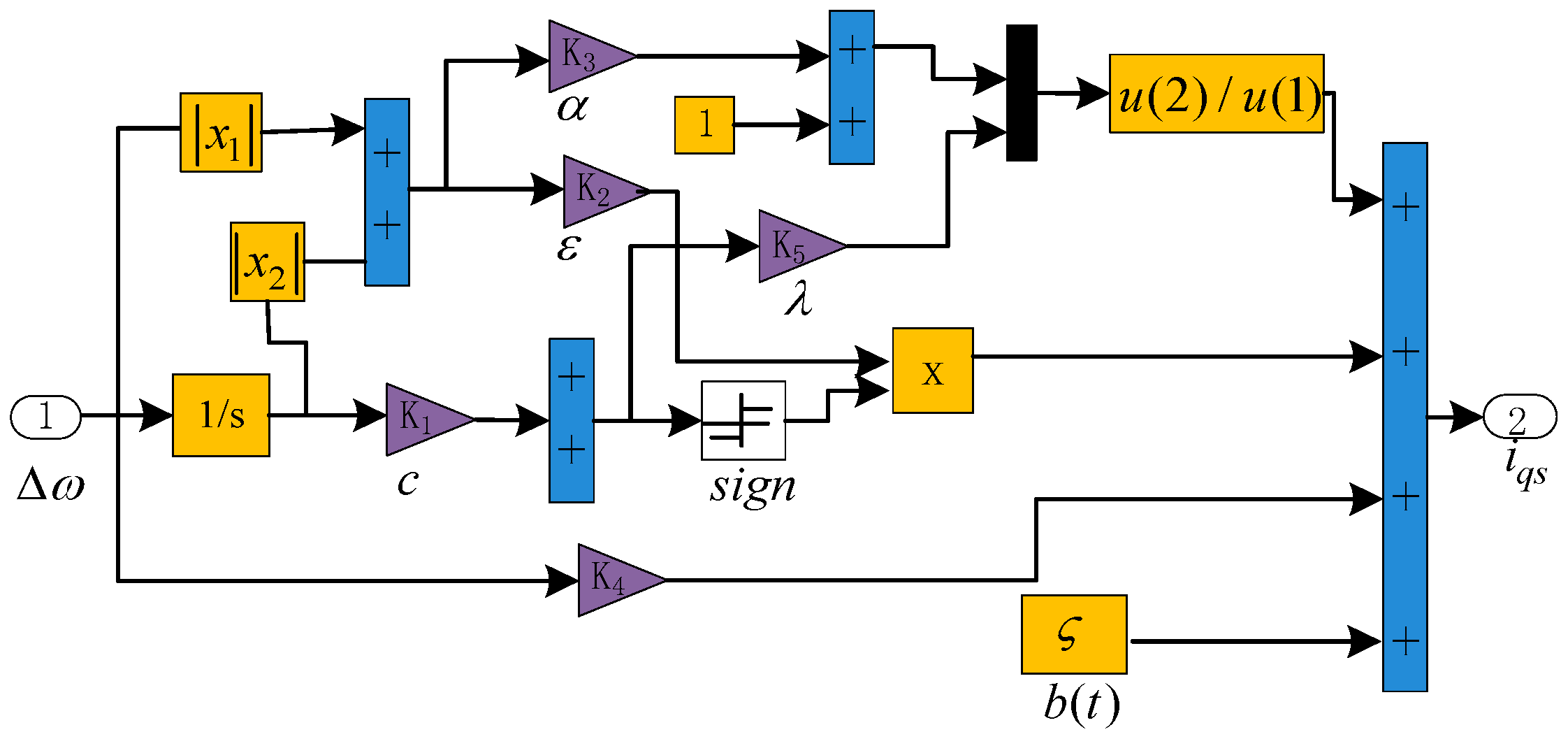
2. Design of the Adaptive Variable-Rated Exponential Reaching Law and ASMC

A nonlinear control system can be described as:
{ x ˙ = f ( t , x ) + g ( t , x ) u + b ( t ) s = s ( t , x )
where x = [ x 1 , x 2 ] T is the system state variable; g ( t , x ) 0 ; b ( t ) is the uncertain disturbances of system, | b ( t ) | ς and ς is the upper bound of disturbance; u R n can be expressed by the following equation:
u i ( x , t ) = { u i + ( x , t ) , s i ( x ) > 0 u i ( x , t ) , s i ( x ) < 0
where s i ( x ) is a switching function and can be given as:
s i ( x ) = { x R n ; s i ( x ) = 0 } , i = 1 , 2 , k
Under the control of u i ( x , t ) , the system runs along the sliding mode surface and obtains higher control performance. However, as a kind of discrete switch, the sliding mode variable structure has chattering. Thus, Gao Weibing, a control theory expert in China, designed a exponential reaching law to eliminate the chattering [23]. The function is written as:
s ˙ = ε sgn ( s ) λ s
The reaching law improved the quality of the sliding mode to some degree, but taking its banded switching strip into consideration, the system just moved back and forth around the origin and chattered near the origin. The chattering affects the performance of the controller. In addition, ε and λ didn’t have the automatic adjustment function according to the position of the state variables, so it can’t reach the best convergence property. Devoting to solving the problems above, this paper proposes a new exponential reaching law—the adaptive variable-rated exponential reaching law:
{ s ˙ = ε x 1 sgn ( s ) λ 1 1 + α x 1 s lim t x 1 = 0
where x 1 = i = 1 n | x | is the L 1 norm of state variables and λ > 0 , ε > 0 , c > 0 , n > 0 .
The approach speed of the system is associated with the distance between the state variable and the stable point under control of the adaptive variable-rated exponential reaching law. When the system state variables are far away from the sliding mode surface, the system state variables are mainly close to the sliding mode surface through λ s / ( 1 + α x 1 ) . At the same time, it can accelerate the system’s approach speed by reducing the value of α. When the system state variables are already near the sliding mode surface, ε x 1 sgn ( s ) plays a key role. As the state variables are close to the stable point, the x 1 is decreasing and gets close to zero. This makes the value of ε x 1 sgn ( s ) zero. Hence, it weakens the chattering caused by the constant speed ε sgn ( s ) , and the sliding mode dynamics will stabilize at the origin. In addition, the sign function can be processed as shown in Formula (6) to achieve the purpose of further weakening chattering [24]:
sgn ( s ) = s | s | + δ
where δ is a positive constant.
Considering the high-frequency noise in the traditional sliding mode surface, this paper selects the first-order integral sliding mode surface. It can smooth the speed, reduce the system overshoot and suppress the chattering. The design of ASMC is defined as Theorem 1.
Theorem 1. 
For the nonlinear control system shown in (1), the integral sliding mode surface is chosen as:
s = x 1 + c 0 x 2
The controller is designed as:
u = g 1 ( t , x ) [ f ( x ) b ( t ) C 1 ε x 1 sgn ( s ) C 1 λ 1 1 + α x 1 s ]
where C = [ 1 c 0 ] . From above, it can be seen that the system can converge to the stable point in a limited time.
Stability Proof of Theorem 1. 
According to the Lyapunov stability theory, the existence and reachability of sliding mode are expressed as:
V ˙ = s s ˙ < 0
Formula (9) is combined with Formula (5). Then, Formula (9) turns into:
s s ˙ = s ( ε x 1 sgn ( s ) λ 1 1 + α x 1 s ) = ε x 1 | s | λ 1 1 + α x 1 s 2 < 0
Hence, the adaptive variable-rated exponential reaching law meets the demand of the Lyapunov stability theory. The system can arrive at the sliding mode surface within a limited time from any state.
In addition, by a typical nonlinear system { x ˙ = A x + B u + D s = C x , an SMC and an ASMC are designed, respectively, based on the index reaching law and adaptive variable-rated exponential reaching law to verify the superiority of the proposed method in this paper, where A = [ 0 12 0 0 ] , B = [ 0 150 ] , C = [ 1 10 ] , and D = [ 1 ] . The initial state variables are set as X ( 0 ) = [ 6 6 ] . The simulation results are shown in Figure 1. It can be seen from the diagram that the ASMC has faster convergence speed and smaller chattering than the SMC.

3. Design of the BIM Speed ASMC

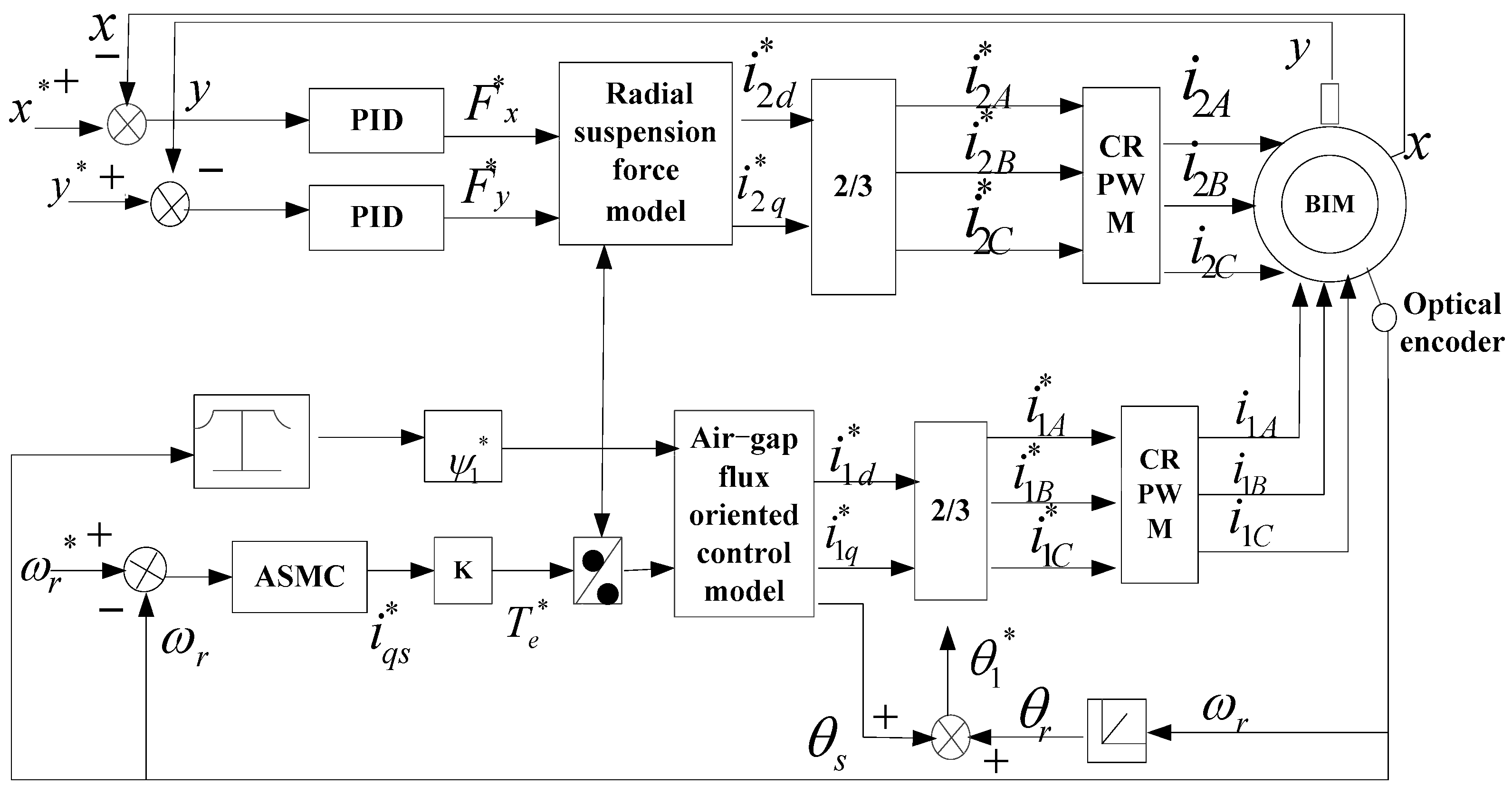
3.1. The Dynamics Model of BIM

BIM is formed by superimposing other radial levitation force windings in the stator. The rapid rotation and stable suspension of the rotor are realized by controlling the winding current to change the distribution of the air-gap magnetic field. In the d-q coordinate system, the rotor voltage equation in torque windings of BIM is established as:
{ U 1 r d = R 1 r i 1 r d + p ψ 1 r d ( ψ 1 q + L 1 r l i 1 r q ) ( ω 1 ω r ) = 0 U 1 r q = R 1 r i 1 r q + p ψ 1 r q + ( ψ 1 d + L 1 r l i 1 r d ) ( ω 1 ω r ) = 0
Air-gap flux linkage equation is given as:
{ ψ 1 d = L 1 m ( i 1 s d + i 1 r d ) ψ 1 q = L 1 m ( i 1 s q + i 1 r q )
The electromagnetic torque equation is set up as:
T e = p 1 ( i 1 s q ψ 1 d i 1 s d ψ 1 q )
The equation of motion is written as:
T e T l = J P 1 d ω r d t
where the subscript “1” represents the torque windings, the subscript “2” represents radial levitation force windings, the subscript “ s ” represents stator and the subscript “ r ” represents rotor; i 2 s d and i 2 s q are current components of the stator in levitation force winding under the d-q axis; ω 1 is the air-gap field speed; ω r is the rotor speed; J is the rotational inertia of the rotor; T l is the load torque; and p is the differential operator.
The radial levitation force is described as
{ F x = K ( i 2 s d ψ 1 d + i 2 s q ψ 1 q ) F y = K ( i 2 s q ψ 1 d i 2 s d ψ 1 q )
where K = K m + K l , K m = π p 1 p 2 L 2 m 18 l r μ 0 N 1 N 2 , and K l = p 1 N 2 2 r N 1 ; p1 and p2 are pole pairs of the torque windings and suspension windings, respectively; L 2 m is mutual inductance of the levitation force windings; l is the effective length of the rotor; r is the stator inner diameter; μ 0 is the permeability of vacuum; N 1 and N 2 , respectively, show the effective number of turns of the torque windings and the levitation force windings; ψ1d and ψ1q, respectively, mean the components of flux linkage for the torque winding in the d-q axis.
Because of the magnetic field coupling [25] existing in the radial levitation force and the electromagnetic torque, the air-gap field-oriented control is used to decouple:
ψ 1 d = ψ 1 , ψ 1 q = 0
After plunging Formula (16) into Formula (12) and combining with Formula (11), the slip ω s and i 1 s d can be calculated as:
ω s = ( 1 + T 1 r l p ) i 1 s q T 1 r L 1 m Ψ 1 T 1 r l i 1 s d
i 1 s d = 1 1 + T 1 r l p [ ( 1 + T 1 r p ) ψ 1 L 1 m + ω s T 1 r l i 1 s q ]
where ω s = ω 1 ω r ; i 1 s d is an excitation component of the torque winding current; T 1 r l = L 1 r l / R 1 r ; T 1 r is a time constant of the rotor, T 1 r = L 1 r / R 1 r .
Then, the electromagnetic torque can be simplified as:
T e = P 1 ψ 1 i 1 s q
At the same time, the radial levitation force can be simplified as:
{ F x = K i 2 s d ψ 1 F y = K i 2 s q ψ 1
From Formulas (19) and (20), it can be seen that the radial levitation force and torque, respectively, are relevant to their own winding current. Hence, the radial levitation force and electromagnetic torque have been decoupled.

3.2. The Design of the Speed of the ASMC

The speed regulation system of BIM is shown in Figure 2. The input of ASMC is the difference between the given speed ω * and the actual speed ω . The output of ASMC is the current i q s * .
The system state variables are defined as:
{ e ω 1 = ω * ω e ω 2 = t e ω 1 d t
Differentiating (21) with respect to time and by substituting (14), e ω 1 can be obtained as:
e ω 1 = ω = p 1 2 ψ 1 J i q s + p 1 J T l
Because of a lot of uncertain disturbances in motor system, e ω 1 can be given as:
e ω 1 = ( p 1 2 ψ 1 J + Δ ζ ) i q s + ( p 1 J + Δ η ) T l + Δ ξ
where Δ ζ and Δ ξ are the uncertain disturbances; | Δ ζ | ς 1 ; | Δ ξ | ς 2 ; and ς 1 and ς 2 are bounded constants.
Here, b ( t ) is recorded as the total disturbance factors of the system (including load). Then, (12) can be simplified as:
e ω 1 = p 1 2 ψ 1 J i q s + b 1 ( t )
where b 1 ( t ) = ( Δ ζ ) i q s + ( p 1 J + Δ η ) T l + Δ ξ ; | b 1 ( t ) | ς and ς is a bounded positive constant.
Therefore, the system state equation of speed error is written as:
{ e ω 1 = ω = p 1 2 ψ 1 J i q s + b 1 ( t ) e ω 2 = e ω 1 = ω * ω
When the system enters sliding mode motion, differentiating s = e ω 1 + c e ω 2 = 0 with respect to time and the answer is computed as:
e ω 1 = c Δ e t / c
As shown above, the velocity of the speed error approaching zero is e 1 / c . Moreover, it can track the speed without overshoot. Therefore, we can get the desired dynamic characteristics of the sliding mode motion by adjusting c .
Differentiating s = e ω 1 + c e ω 2 with respect to time, s is given as:
s = e ω 1 + c e ω 2 = p 1 2 ψ 1 J i q s + b 1 ( t ) + c e ω 1
Using (5) and (27), it can be obtained as:
ε e ω 1 sgn ( s ) λ 1 1 + α e ω 1 s = p 1 2 ψ 1 J i q s + b 1 ( t ) + c e ω 1
The controller can be described finally as:
i q s = J p 1 2 ψ 1 ( ε e ω 1 sgn ( s ) + λ 1 1 + α e ω 1 s + b 1 ( t ) + c e ω 1 )
The design of ASMC for BIM is defined as Theorem 2 in this paper.
Theorem 2. 
For the speed error control system shown in (25), the sliding mode surface is adopted as:
s 1 = e ω 1 + c e ω 2
The controller is obtained as:
i q s = J p 1 2 ψ 1 ( ε e ω 1 sgn ( s ) + λ 1 1 + α e ω 1 s + b 1 ( t ) + c e ω 1 )
It can be seen that the speed error can converge to the expected place within a limited time, where λ , ε and α are system parameters and c is the integral constant.

4. Simulation and Experiment Research

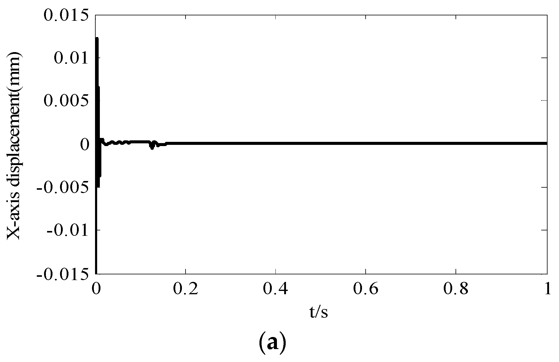
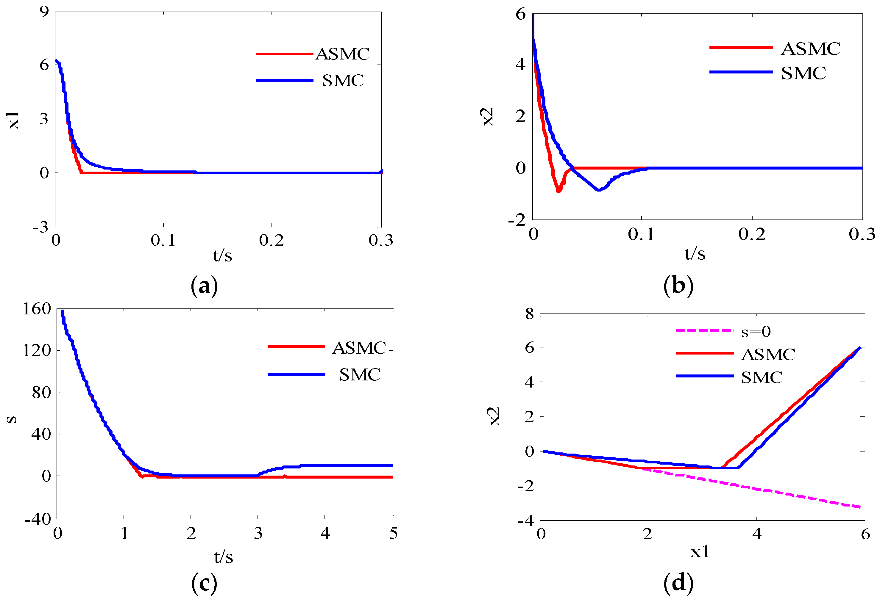
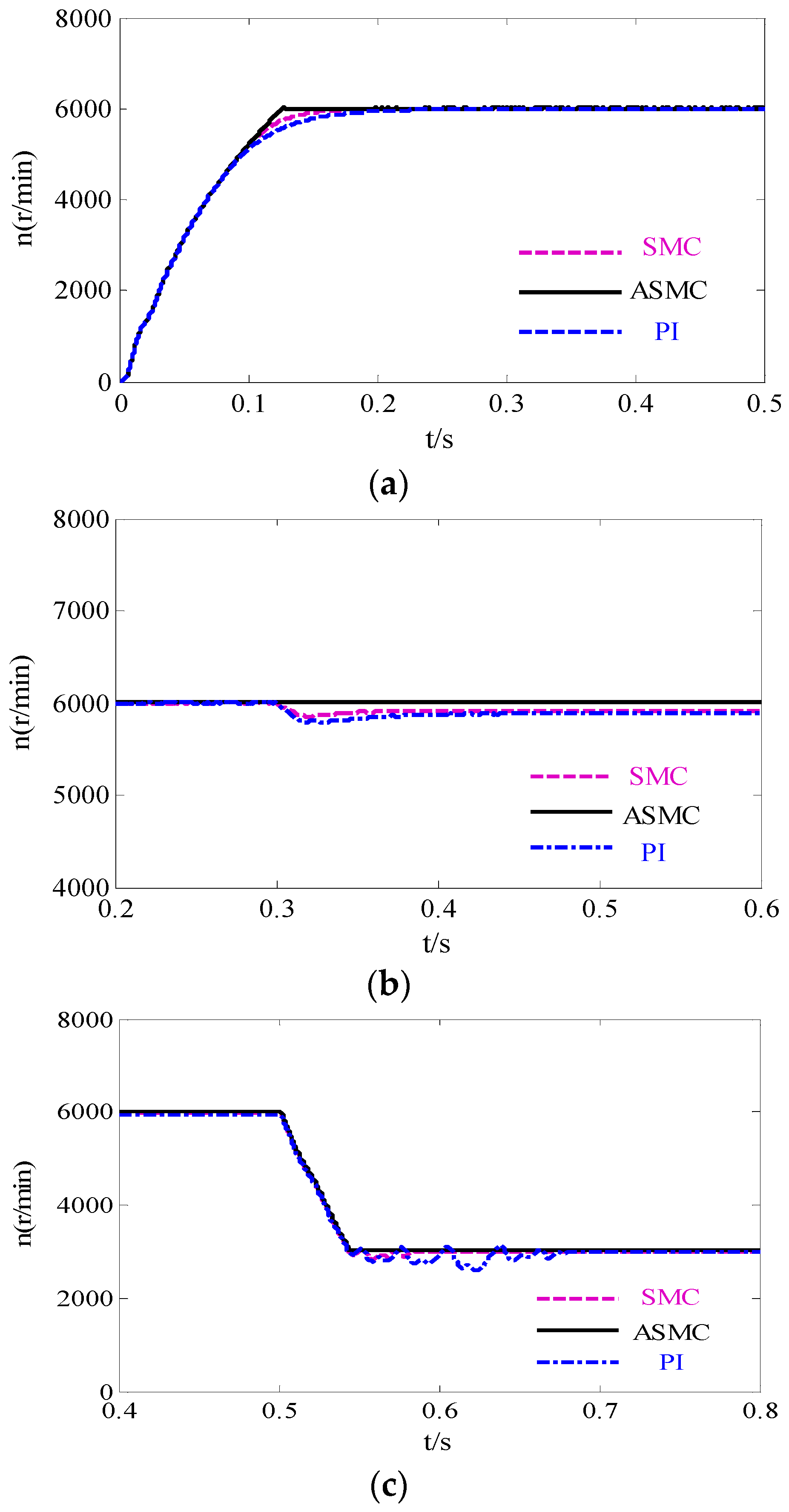
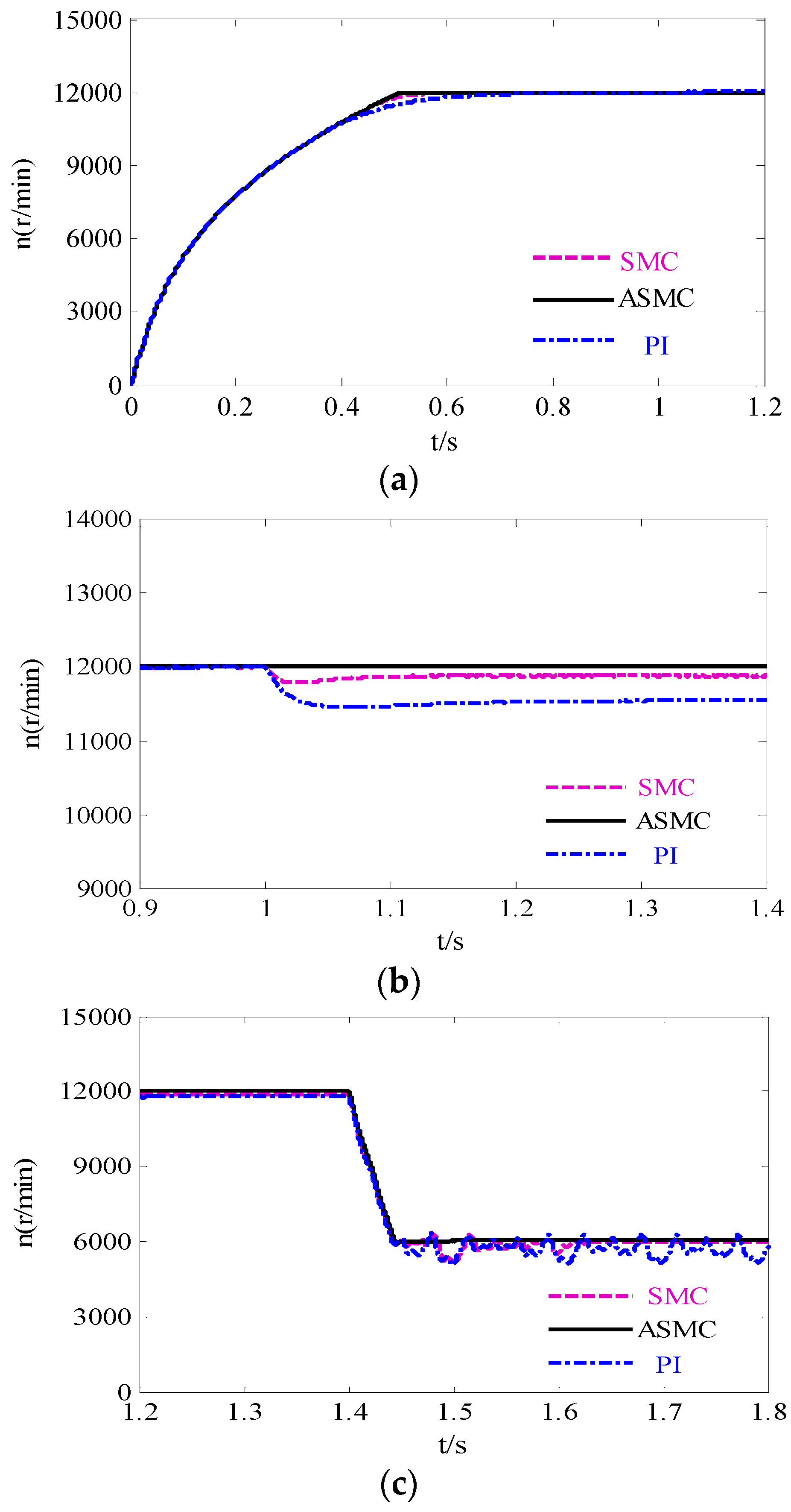
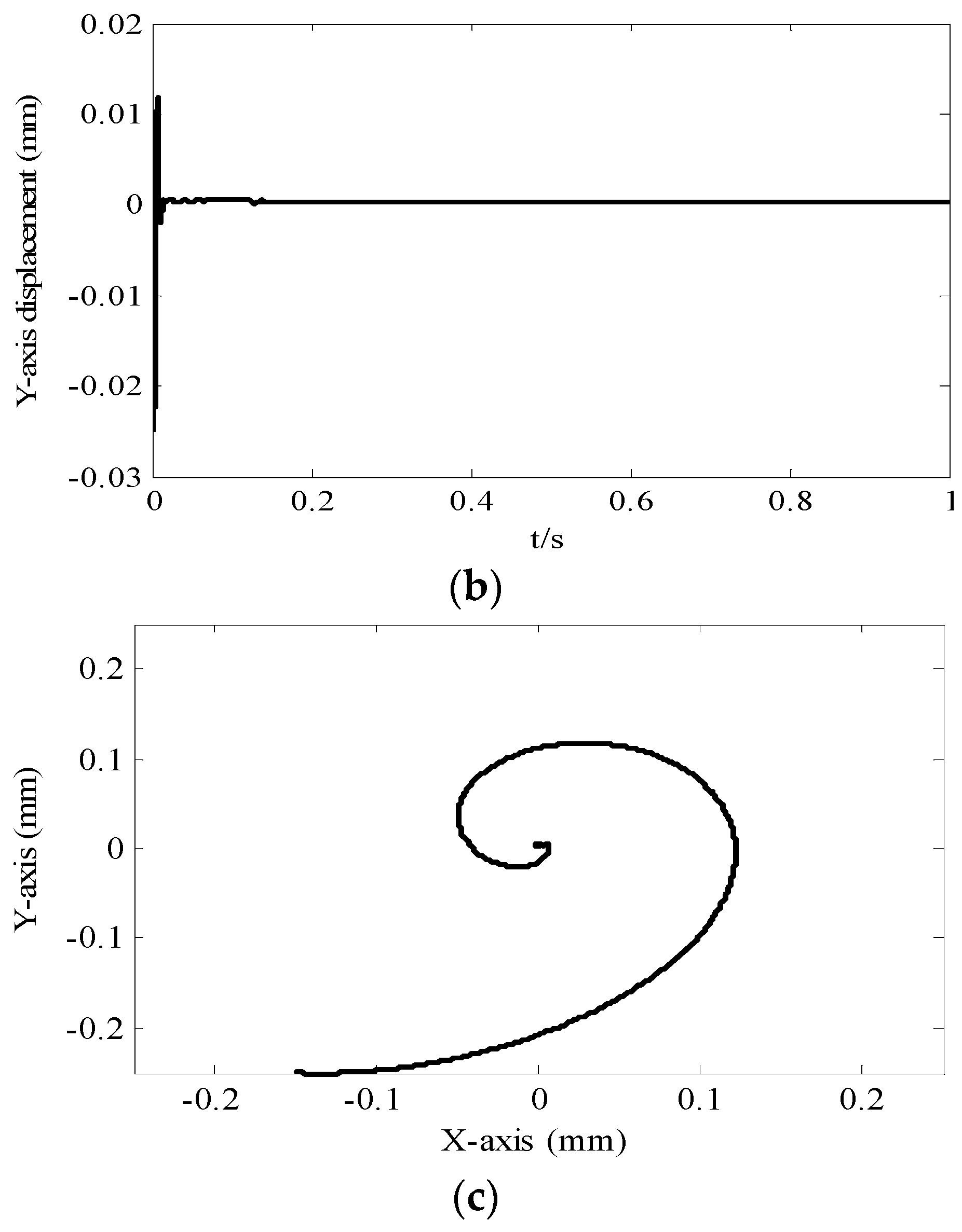
4.1. Results and Analysis of the Simulation

To verify the effectiveness of the speed ASMC for BIM speed regulating system, a simulation control system was constructed by using the Matlab/Simulink toolbox. The proposed ASMC is shown in Figure 3. The specific parameters of BIM are shown in Table 1. The parameters of the ASMC are shown as follows: ε = c = 9 ; λ = 2 ; α = 100 ; ς = 10 ; and δ = 0.01 . The parameters of the PI are k p = 1 and k i = 0.001 .
Figure 4 presents the simulation results of BIM controlled by the PI controller, SMC and ASMC under different working conditions. Figure 4a shows the simulation of the rotor operates at the speed of 6000 r/min with no-load. Figure 4b,c shows the simulation results of the system working in the condition of sudden load (5 N·m) and speed mutation (6000 r/min drops to 3000 r/min). Compared with ASMC, it can be known from Figure 4 that the system runs slowly at first under the control of PI controller and SMC. When the system is attacked by the sudden load or speed mutation, the speed has obvious fluctuation. The system needs more time to stabilize and it is unable to return to the original speed. The PI controller and SMC appear to have poor control performance.
The high speed (12,000 r/min) simulation results of BIM are shown in Figure 5. First of all, the system runs at 12,000 r/min with zero-load. Then, the load 5 N·m is given to the system. At last, the speed falls sharply from 12000 r/min to 6000 r/min. The waveforms of the system working on the conditions above separately are shown in Figure 5a–c. Suffering the external disturbances, the speed has big overshoot and operates at a steady state slowly when the system adopts the PI controller or SMC. At the same time, the value of the speed is very different from the original speed. However, the system using the ASMC responds quickly. When the system is affected by the external disturbances, the fluctuation of speed is small and it restores itself to the original value quickly. It shows that the ASMC has excellent robustness. In addition, by contrasting Figure 4 and Figure 5, we can know that the adverse influence of disturbance to speed regulation system will be more serious if the motor runs faster. Therefore, to design a controller with strong ability to resist disturbance is very important.
Figure 6 shows the radial displacement simulation diagrams of the system operating at the speed of 12,000 r/min under the control of ASMC. It is described in the diagrams that the rotor still can approach a stable position quickly and suspend steadily even if the system is running at high speed. Good control performance of ASMC is verified.

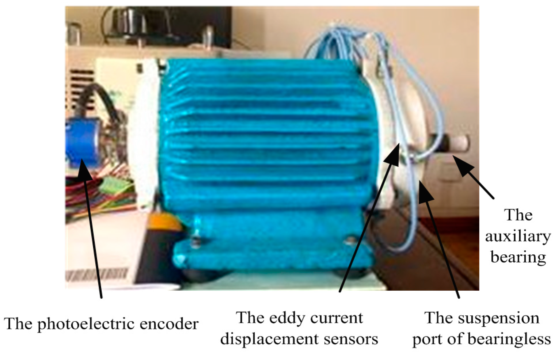
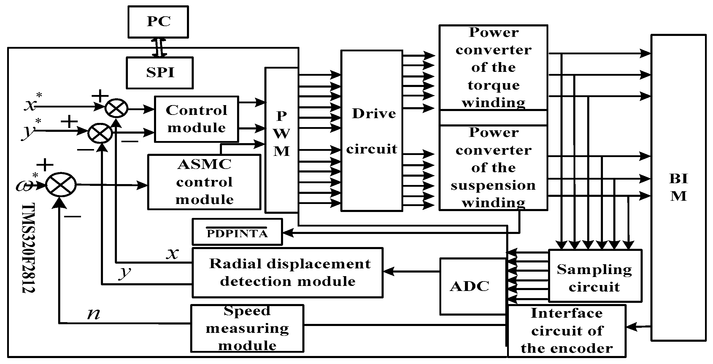
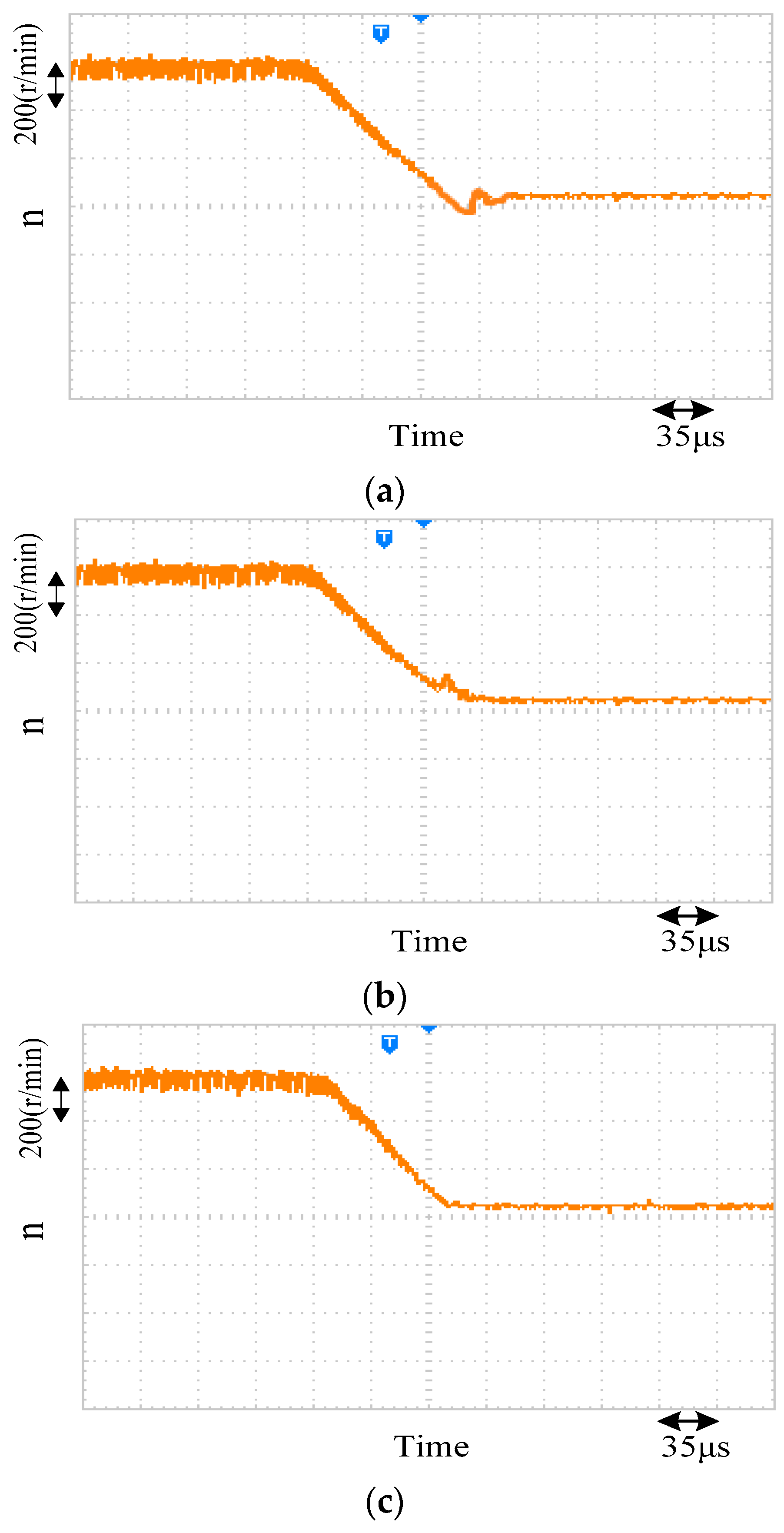
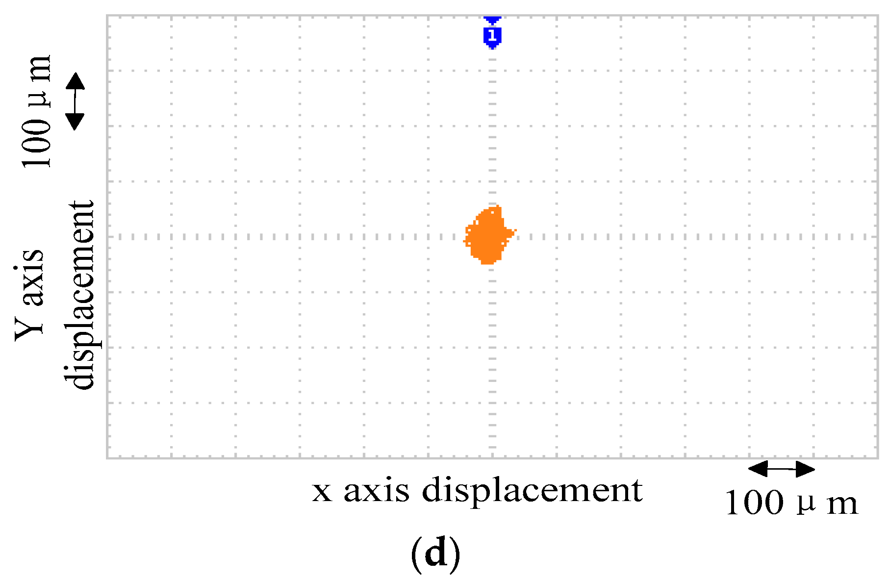
4.2. Results and Analysis of the Experiment

Using the experimental object of BIM as shown in Figure 7, the digital control system experimental platform is conducted to further prove the effectiveness of the proposed sliding mode control method. The experiment block diagram of the control system is shown in Figure 8. The photoelectric encoder and the eddy current displacement sensors are used to detect the speed signals and radial displacement signals of rotor, respectively. With the signals, the speed measuring module and the radial displacement detection module can acquire the actual speed and displacement of rotor. After contrasting the actual speed and the given speed (or the actual displacement and the given displacement), the drive circuit controls the two kinds of windings according to the Pulse-Width Modulation signals generated by TMS320F28335, so the rotor can rotate and be suspended. Furthermore, the sampling circuit can detect the feedback circuit from the torque windings and suspension windings. With it, the rotor can adjust the running state in time. The prototype parameters are the same as the simulation parameters. Considering the limitations of photoelectric coder measuring speed, the speed is set to 2000 r/min in the process of the experiment. The air gap of the motor auxiliary bearing is 0.4 mm. The experimental results are shown in Figure 9.
Figure 9a–c separately show the results of the system speed falling sharply from 2000 r/min to 1400 r/min under the control of PI, SMC and ASMC. From the waveforms, it can be found that the system has faster speed response, better stability and stronger robustness under the ASMC compared to the PI controller and SMC.
Figure 9d provides the curve of rotor radial displacement at the speed of 2000 r/min under the control of ASMC. It shows that the center of the rotor runs near the equilibrium position and the biggest offset value of the radial displacement is 80 μm, which is far less than the value of the air gap of motor. It proves that the rotor can be suspended steadily under the control of ASMC.

5. Conclusions

In order to further optimize the operation quality of the BIM drive system, an adaptive variable-rated exponential reaching law is proposed on the basis of analyzing the conventional exponential reaching law. The proposed reaching law can adjust the approach speed adaptively according to the distances between the state variables and expected points. Moreover, it can suppress system chattering. The simulation and experimental results show that the speed controller of BIM, which is designed on the basis of the adaptive variable-rated exponential reaching law can make the system run faster, strengthen the robustness of the system and improve the operation quality of the BIM speed regulation system. In addition, the control strategy is simple and can be applied to engineering easily.

Acknowledgments

This work was supported by the National Natural Science Foundation of China under Project 51475214, 61104016 and 51305170, the China Postdoctoral Science Foundation funded project under Project 2015T80508 and 2014T70482, the Natural Science Foundation of Jiangsu Province of China under Project BK20130515, BK20141301and BK20150524, the Professional Research Foundation for Advanced Talents of Jiangsu University under Project BK20150524 and 14JDG076, and Six Categories Talent Peak of Jiangsu Province under Project ZBZZ-017, and the Priority Academic Program Development of Jiangsu Higher Education Institutions.

Author Contributions

Zebin Yang and Ling Wan proposed the new idea of the Sliding Mode Variable Structure Control of Bearingless Induction Motor Based on a Novel Reaching Law. Ling Wan derived the equations. Xiaodong Sun set up the simulation model. Fangli Li was in charge of analyzing the data. Lin Chen checked the language. All authors were involved in preparing the manuscript.

Conflicts of Interest

The authors declare no conflict of interest.

Abbreviations

BIMBearingless Induction Motor.
ASMCAdaptive variable-rated sliding mode controller.
PMSMPermanent magnet synchronous motor.
SMCSliding mode controller.
DCDirect current.
PIProportional-Integral

References

  1. De Almeida, A.T.; Ferreira, F.J.T.E.; Quintino, D.A. Technical and Economical Considerations on Super High-Efficiency Three-Phase Motors. IEEE Trans. Ind. Appl. 2014, 50, 1274–1285. [Google Scholar] [CrossRef]
  2. Sun, X.D.; Chen, L.; Yang, Z.B. Overview of bearingless permanent magnet synchronous motors. IEEE Trans. Ind. Electron. 2013, 60, 5528–5538. [Google Scholar] [CrossRef]
  3. Sinervo, A.; Arkkio, A. Rotor radial position control and its effect on the total efficiency of a bearingless induction motor with a cage rotor. IEEE Trans. Magn. 2014, 50, 1–9. [Google Scholar] [CrossRef]
  4. Yang, Z.B.; Dong, D.W.; Gao, H.Y.; Sun, X.D.; Fan, R.; Zhu, H.Q. Rotor mass eccentricity vibration compensation control in bearingless induction motor. Adv. Mech. Eng. 2015, 7. [Google Scholar] [CrossRef]
  5. Chiba, A.; Asama, J. Influence of rotor skew in induction type bearingless motor. IEEE Trans. Magn. 2012, 48, 4646–4649. [Google Scholar] [CrossRef]
  6. Hou, B.J.; Gao, J.S.; Li, X.Q.; Zhou, Y.F. Study on repetitive PID control of linear motor in wafer stage of lithography. Procedia Eng. 2012, 29, 3863–3867. [Google Scholar] [CrossRef]
  7. Sun, X.D.; Chen, L.; Yang, Z.B.; Zhu, H.Q. Speed-sensorless vector control of a bearingless induction motor with artificial neural network inverse speed observer. IEEE/ASME Trans. Mechatron. 2013, 18, 1357–1366. [Google Scholar] [CrossRef]
  8. Sun, X.D.; Chen, L.; Jiang, H.B.; Yang, Z.B.; Chen, J.C.; Zhang, W.Y. High-performance control for a bearingless permanent magnet synchronous motor using neural network inverse scheme plus internal model controllers. IEEE Trans. Ind. Electron. 2016, 63, 3479–3488. [Google Scholar] [CrossRef]
  9. Zhang, H.S.; Wang, P.; Han, B.C. Rotor Position Measurement for High-speed Permanent Magnet Synchronous Motors Based on Fuzzy PI MRAS. Proc. Chin. Soc. Electr. Eng. 2014, 34, 1889–1896. (In Chinese) [Google Scholar]
  10. Mercorelli, P. An Antisaturating Adaptive Preaction and a Slide Surface to Achieve Soft Landing Control for Electromagnetic Actuators. IEEE/ASME Trans. Mechatron. 2012, 17, 76–85. [Google Scholar] [CrossRef]
  11. Wang, X.D.; Liu, G. Sensorless Control of High Speed Permanent Magnet Synchronous Motor Based on Modified Sliding-Mode Observer. Adv. Mater. Res. 2014, 986–987, 1134–1137. [Google Scholar] [CrossRef]
  12. Shi, T.N.; Xiao, Z.X.; Xiao, Y.W.; Xia, C. A Position Sensorless Control Strategy for BLDCM Based on an Improved Sliding Mode Observer. Proc. Chin. Soc. Electr. Eng. 2015, 35, 2043–2051. [Google Scholar]
  13. Mercorelli, P. A Two-Stage Sliding-Mode High-Gain Observer to Reduce Uncertainties and Disturbances Effects for Sensorless Control in Automotive Applications. IEEE Trans. Ind. Electron. 2015, 62, 5929–5940. [Google Scholar] [CrossRef]
  14. Li, S.H.; Wu, C.; Sun, Z. Design and Implementation of Clutch Control for Automotive Transmissions Using Terminal-Sliding-Mode Control and Uncertainty Observer. IEEE Trans. Veh. Technol. 2016, 65, 1890–1898. [Google Scholar] [CrossRef]
  15. Serna-Garcés, S.I.; Gonzalez Montoya, D.; Ramos-Paja, C.A. Sliding-Mode Control of a Charger/Discharger DC/DC Converter for DC-Bus Regulation in Renewable Power Systems. Energies 2016, 9, 245. [Google Scholar] [CrossRef]
  16. Lin, F.-J.; Shen, P.-H. Robust Fuzzy Neural Network Sliding-Mode Control for Two-Axis Motion Control System. IEEE Trans. Ind. Electron. 2006, 53, 1209–1225. [Google Scholar] [CrossRef]
  17. Zhu, Y.; Cheng, M.; Hua, W.; Zhang, B.; Wang, W. Sensorless Control for Electrical Variable Transmission Based on Sliding Mode Model Reference Adaptive System. Diangong Jishu Xuebao 2015, 30, 64–72. (In Chinese) [Google Scholar]
  18. Zhang, X.G.; Sun, L.; Zhao, K. Sliding mode control of PMSM based on a novel load torque sliding mode observer. Proc. Chin. Soc. Electr. Eng. 2012, 32, 111–116. (In Chinese) [Google Scholar]
  19. Asad, M.; Bhatti, A.I.; Iqbal, S.; Asfia, Y. A smooth integral sliding mode controller and disturbance estimator design. Int. J. Control Autom. Syst. 2015, 13, 1326–1336. [Google Scholar] [CrossRef]
  20. Guo, J.G.; Jian, X.P.; Lin, G.Y. Performance Evaluation of an Anti-Lock Braking System for Electric Vehicles with a Fuzzy Sliding Mode Controller. Energies 2014, 7, 6459–6476. [Google Scholar] [CrossRef]
  21. Xu, B.; Zhu, H.Q. Adaptive nonsingular terminal sliding model control and its application to BPMSM. Control Decis. 2014, 29, 833–837. [Google Scholar]
  22. Yi, B.Y.; Kang, L.Y.; Tao, S.N.; Guo, H. Design of Robust High Order Sliding Mode Observer for Permanent Magnet Synchronous Motors. Diangong Jishu Xuebao 2014, 29, 132–140. (In Chinese) [Google Scholar]
  23. Gao, W.B. Variable Structure Control Theory; Science and Technology Press: Beijing, China, 1990; pp. 28–30. [Google Scholar]
  24. Kim, M.; Song, D. A robust control of Permanent magnet synchronous Motor using Load Torque Estimation. In Proceedings of the IEEE International Symposium on Industrial Electronics, Pusan, Korea, 12–16 June 2001; pp. 1157–1162.
  25. Yang, Z.B.; Sun, X.D.; Wang, M.T.; Zhu, H.Q. Decoupling control of bearingless induction motors based on least squares support vector machine inverse. J. Comput. Theor. Nanosci. 2014, 11, 1403–1409. [Google Scholar] [CrossRef]
Figure 1. The performance contrast of adaptive variable-rated sliding mode controller (ASMC) and sliding mode controller (SMC): (a) The response of x 1 ; (b) The response of x 2 ; (c) The time of approach process; and (d) The phase track of system.
Energies 09 00452 g001
Figure 2. Control diagram of Bearingless Induction Motor (BIM) speed regulation system.
Energies 09 00452 g002
Figure 3. The proposed ASMC.
Energies 09 00452 g003
Figure 4. Waveforms of the speed dynamic response (6000 r/min): (a) The response of speed under no-load; (b) The response of speed under the sudden load (5 N·m); (c) The response of speed mutation under the torque disturbance (from 6000 r/min to 3000 r/min).
Energies 09 00452 g004
Figure 5. The simulation of system dynamic response (12,000 r/min): (a) The response of speed under no-load; (b) The response of speed under the sudden load (5 N·m); (c) The response of speed mutation under the torque disturbance (from 12,000 r/min to 6000 r/min).
Energies 09 00452 g005
Figure 6. Waveforms of the rotor radial displacement controlled by ASMC (12,000 r/min): (a) The radial displacement on the x-axis; (b) The radial displacement on the y-axis; (c) The curve of rotor operation.
Energies 09 00452 g006aEnergies 09 00452 g006b
Figure 7. Prototype physical diagram.
Energies 09 00452 g007
Figure 8. The experiment block diagram of the control system.
Energies 09 00452 g008
Figure 9. Experimental results of system dynamic response: (a) The diagram of speed mutation controlled by Proportional-Integral (PI); (b) The diagram of speed mutation controlled by SMC; (c) The diagram of speed mutation controlled by ASMC; (d) The diagram of rotor radial displacement controlled by ASMC.
Energies 09 00452 g009aEnergies 09 00452 g009b
Table 1. Parameters of the Bearingless Induction Motor (BIM).
ParametersTorque WindingSuspension Winding
Rated power (Kw)10.5
Rated current (A)2.862.86
Stator resistance (Ω)2.011.03
Rotor resistance (Ω)11.480.075
Mutual inductance of stator and rotor (H)0.158560.00932
Stator leakage inductance (H)0.163100.01199
Rotor leakage inductance (H)0.167780.01474
Rotational inertia (kg·m2)0.007690.00769
Rotor mass (kg)2.852.85
Stator inner diameter (mm)9898
Core length (mm)105105
Pole pairs12

