Article

Torque Ripple Reduction of a Novel Modular Arc-Linear Flux-Switching Permanent-Magnet Motor with Rotor Step Skewing

School of Automation, Beijing Institute of Technology, Beijing 100081, China
*
Author to whom correspondence should be addressed.
Energies 2016, 9(6), 404; https://doi.org/10.3390/en9060404
Submission received: 27 February 2016 / Revised: 2 April 2016 / Accepted: 10 May 2016 / Published: 26 May 2016

Abstract

:
A novel modular arc-linear flux-switching permanent-magnet motor (MAL-FSPM) used for scanning system instead of reduction gearboxes and kinematic mechanisms is proposed and researched in this paper by the finite element method (FEM). The MAL-FSPM combines characteristics of flux-switching permanent-magnet motor and linear motor and can realize the direct driving and limited angular movement. Structure and operation principle of the MAL-FSPM are analyzed. Cogging torque model of the MAL-FSPM is established. The characteristics of cogging torque and torque ripple are investigated for: (1) distance (dend) between left end of rotor and left end of stator is more than two rotor tooth pitch (τp); and (2) dend is less than two rotor tooth pitch. Cogging torque is an important component of torque ripple and the period ratio of the cogging torque to the back electromotive force (EMF) equals one for the MAL-FSPM before optimization. In order to reduce the torque ripple as much as possible and affect the back EMF as little as possible, influence of period ratio of cogging torque to back EMF on rotor step skewing is investigated. Rotor tooth width and stator slot open width are optimized to increase the period ratio of cogging torque to back EMF. After the optimization, torque ripple is decreased by 79.8% for dend > τp and torque ripple is decreased by 49.7% for dend < τp. Finally, 3D FEM model is established to verify the 2D results.

1. Introduction

With the rapid development of society and economy, higher requirements are put forward for energy use, which include being more reliable, flexible, and efficient; adaptive to various actual application situations; etc. Electric energy is one preferable form of energy in daily life and industrial production. Electric energy can be transferred into other forms of energy, such as thermal energy, optical energy, mechanical energy, etc. As is well known, electromechanical systems play the role as a bridge link for energy conversion between electric energy and mechanical energy, and most of the total electric energy is consumed by electromechanical systems [1,2,3,4]. Therefore, improving efficiency of whole electromechanical system is meaningful for energy conversion.
As for an electromechanical system, the actuator is an important factor to influence efficiency of the whole electromechanical system. Since permanent-magnet synchronous motor (PMSM) has advantages of high efficiency, high power density and high power factor, it can be a favorable actuator in the electromechanical system. In [5], two brushless DC motors are used to actuate each of two revolute joints of two degrees of robotic manipulator. In [6], an axial flux permanent-magnet (AFPM) machine is designed for robot joint module. On the other hand, the complexity of electromechanical system, decided by the application domains, also influences the efficiency of the whole electromechanical system. In many applications, such as antenna scanning system, satellite scan mirror system, robot joint, etc., the driven objects only rotate back and force within a limited angle range. In traditional implementation system, rotating electric machines plus reduction gearboxes are usually adopted to convert the rotating motion to linear motion where necessary [6,7,8]. The complex mechanical structure certainly increases power consumption. However, direct drive servomotor can avoid the complex mechanical structure. 
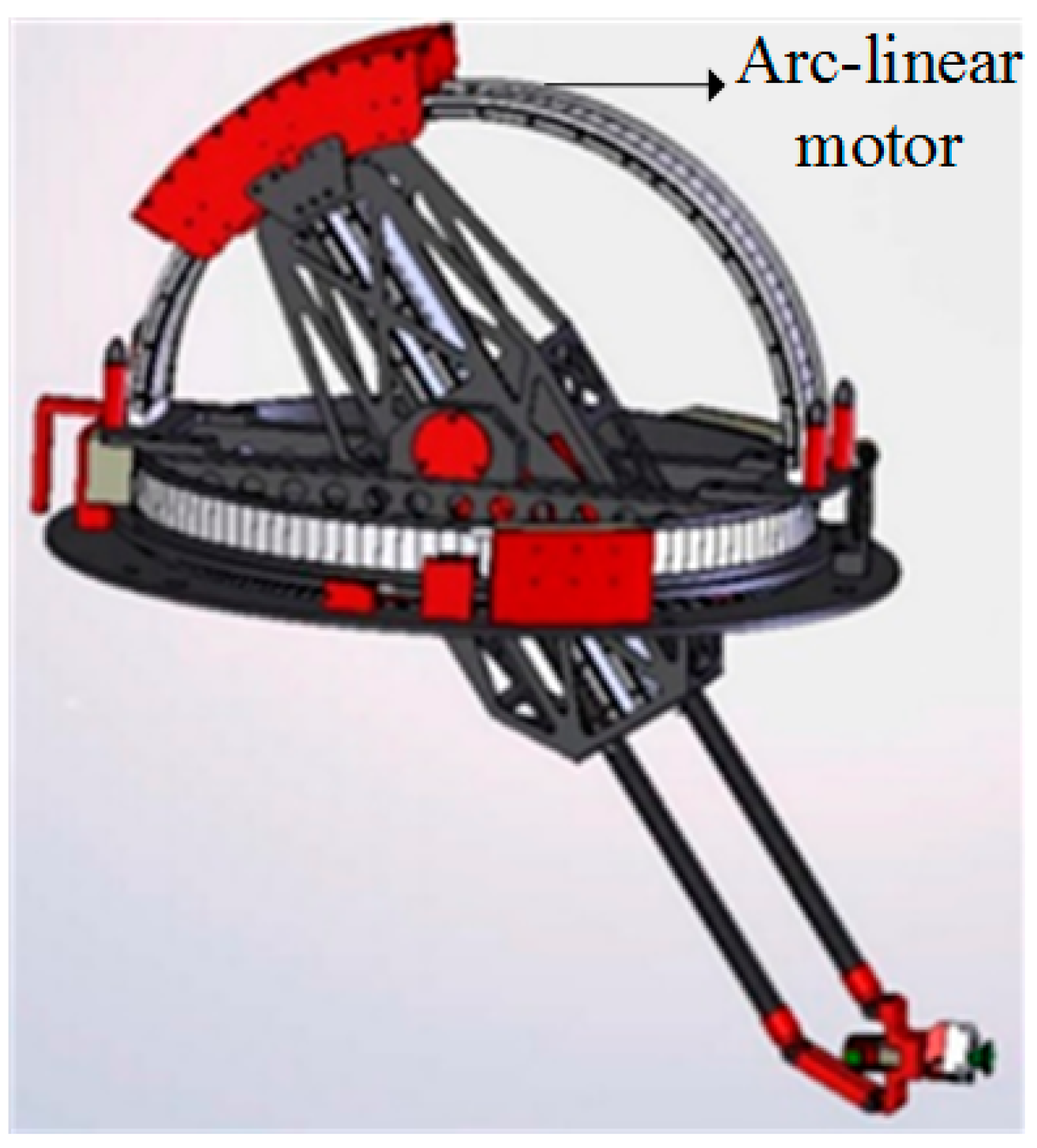
Figure 1 shows one simple example of Galileo Sphere robot [9]. The arc-linear motor can directly drive the load to operate back and force within a limited angle range that is less than 180° (mechanical angle), which saves space and power consumption and improves the performance of the whole robot.
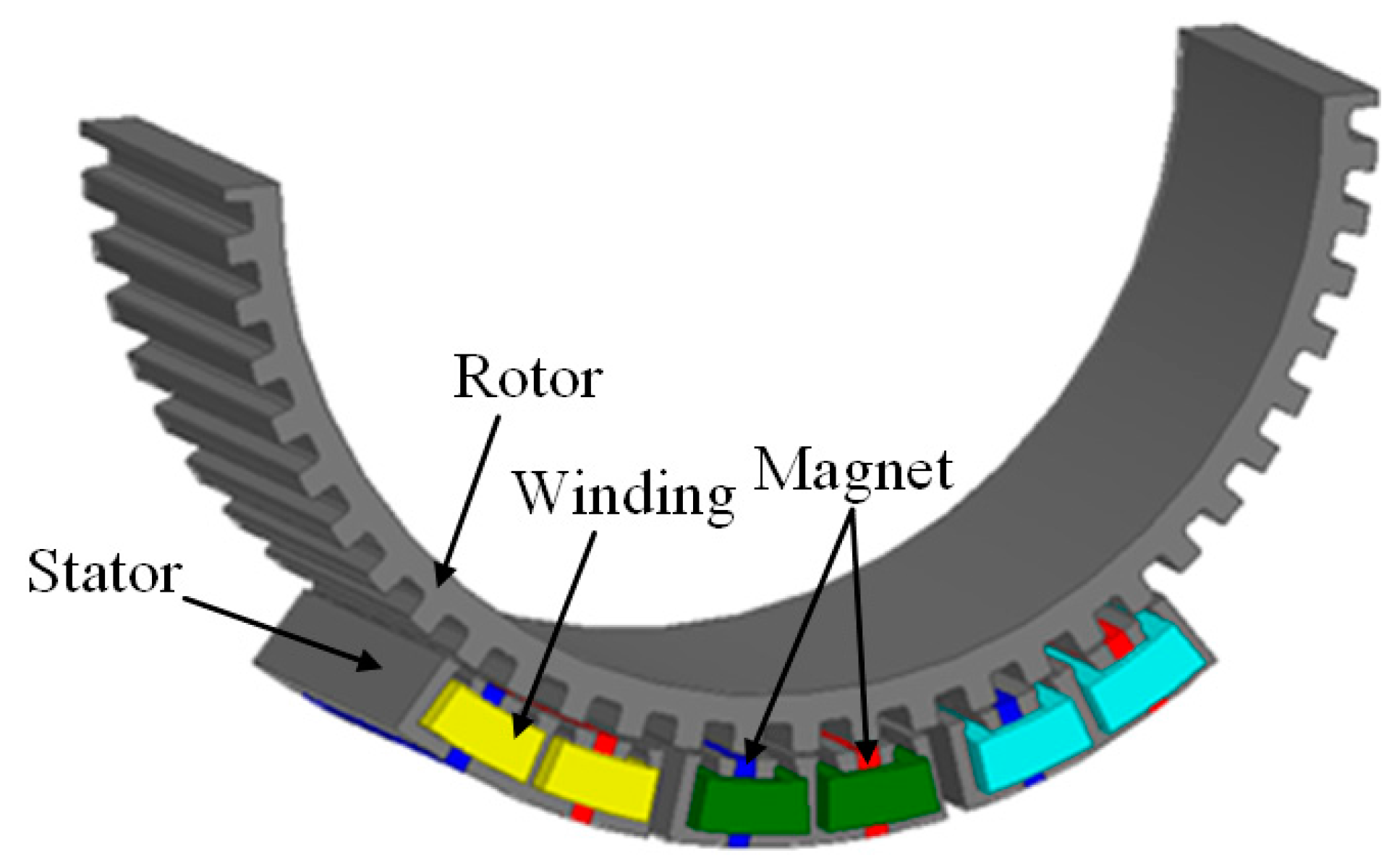
Instead of rotating motor plus reduction gearboxes, arc-linear permanent-magnet synchronous motor (AL-PMSM) is a good candidate as the drive motor directly connecting the load for these aforementioned applications such as antenna scanning system, satellite scan mirror system and robot. It can also satisfy the requirements of high positioning accuracy and high response performance for these applications. Moreover, the direct drive motor can reduce the additional losses, reduce the backlash, and increase the reliability of the system. The arc-linear motors are researched and usually adopt the mover structure with surface-mounted permanent magnets (PMs) [9,10]. However, this kind of AL-PMSM has a limited length of stator structure and PMs are mounted on the whole rotor. Thus, only small parts of PMs are effective during the operation and the PMs that do not produce effective magnetic field may cause electromagnetic interference to peripheral devices. Therefore, this kind of AL-PMSM cannot make full use of the PMs and increases the PMs cost. In recent years, flux reverse permanent-magnet machine (FRPM), double salient permanent-magnet machine (DSPM) and flux-switching permanent-magnet machine (FSPM) have been widely investigated due to the advantages of simple and robust rotor structure that is composed of cheap iron core with salient tooth [11,12,13,14,15]. Since the armature windings and the permanent magnets are both installed in the stator of these structures, they can protect the PMs from sliding off caused by centrifugal force and from demagnetizing caused by the heat dissipation difficulties. Compared with the DSPM and the FRPM, the FSPMs have the performances of high power density and sinusoidal back electromotive force (EMF) [11,16,
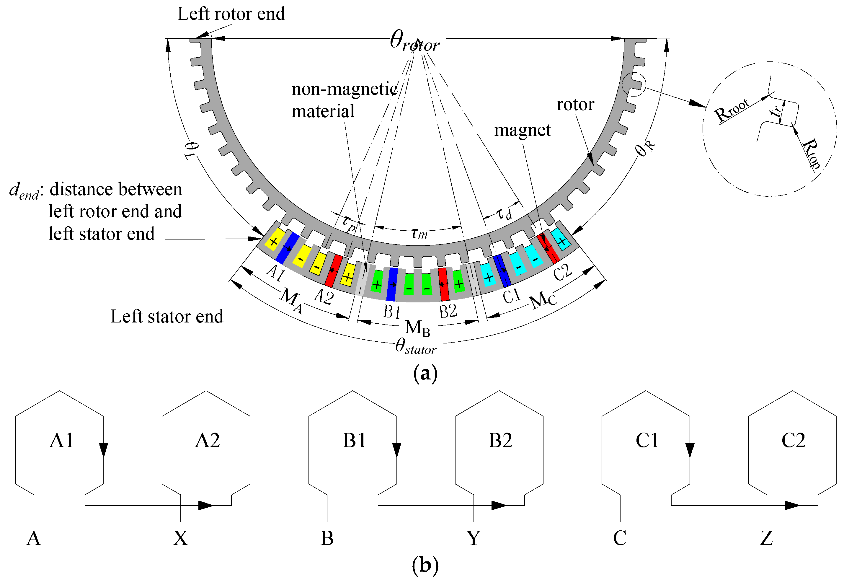
17]. Therefore, this paper researches a novel modular arc-linear flux-switching permanent-magnet motor (MAL-FSPM), which can integrate the merits of high power density and low manufacturing cost, and avoid electromagnetic interference to peripheral devices, as shown in Figure 2. The MAL-FSPM can be applied in robot fields, radar scanning systems, and so on.
However, due to the inherent double salient effect in the FSPM, torque ripple of the FSPM is relatively high [18,19,20], which is unexpected for a direct driving motor. Because the PMs are located in the stator, slots skewing method, magnet segmentation method and optimization of the pole arc coefficient may be ineffective for the FSPM. Therefore, it is good and convenient to optimize the rotor. For the cogging torque and torque ripple reduction of the FSPM, Reference [20] verifies that rotor tooth with odd number has lower cogging torque compared with the rotor tooth with even number; multi-tooth structure can reduce the cogging torque and torque ripple [21,22]; and rotor tooth shapes combined with stepped and notched technology can greatly reduce the cogging torque [23,24,25]. However, these methods may not be all effective for special structure motor, such as the modular motor. Due to the simple rotor structure, rotor skewing technology is an effective and easy way to reduce torque ripple. Detent force of the flux-switching linear motor is greatly reduced by using the skewing technology [
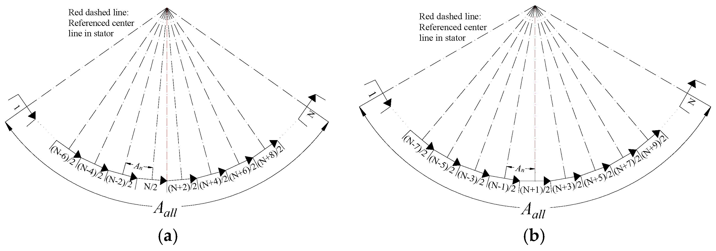
26]. Torque ripple of 12/10 stator/rotor pole and 12/14 stator/rotor pole flux-switching machine topology is effectively reduced based on the rotor step skewing [27]. However, the period ratio of cogging torque to the back EMF is ≥3 in [26,
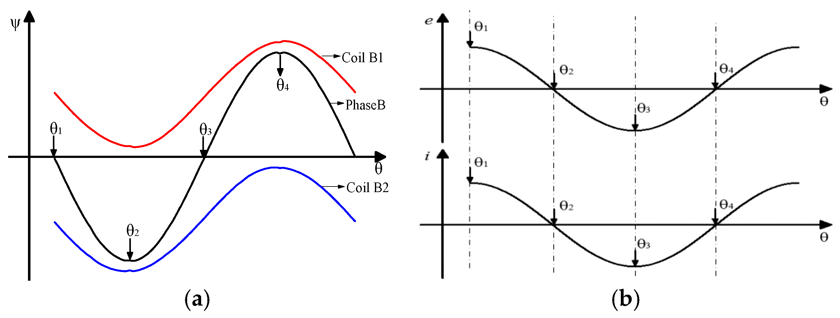
27]. This paper mainly researches torque ripple reduction for modular motor and arc-linear motor, especially for that period ratio of cogging torque to the back EMF equals one.
A novel MAL-FSPM, which can directly drive the load to rotate back and force within a limited angle range, is proposed and researched in this paper. In Section 2, structure and operation principle of the MAL-FSPM are introduced. In Section 3, cogging torque model is established and characteristics of torque ripple are analyzed. In Section 4, influence of period ratio of cogging torque to back EMF on the rotor step skewing is investigated. In Section 5, in order to increase the period ratio of cogging torque to back EMF, first harmonic and second harmonic of cogging torque are dramatically reduced by the optimization of rotor tooth width and stator slot open width. In Section 6, 3D finite element method (FEM) model is established to verify the 2D results.

2. Structure and Operation Principle of the Modular Arc-Linear Flux-Switching Permanent-Magnet Motor

2.1. Structure of the Modular Arc-Linear Flux-Switching Permanent-Magnet Motor

The MAL-FSPM includes one arc stator and one arc rotor. Rotor is laminated by the steel sheet and the rotor arc radian (θrotor) is 180° (mechanical degree). Stator arc radian (θstator) is 76° (mechanical degree). Thus, the scanning range is ±52° (mechanical degree), which is decided by the following Equation (1):
θ L = θ R = ( θ rotor θ stator ) / 2
The effective operating electromagnetic part is a 12-slots/13-poles structure, as shown in Figure 3a. Stator structure of the MAL-FSPM is more complex than rotor structure. The stator consists of three modules, representing Phases A, B and C in the counter-clockwise direction, respectively. Single layer and concentrated windings are placed in each stator slot. Furthermore, each phase windings are connected in series, as shown in Figure 3b. Each module consists of one “E” type iron core, two “U” type iron cores and two PMs. The PMs are inserted between “E” type iron core and “U” type iron core. Magnetization direction of the adjacent PMs is opposite in the circumference direction. Furthermore, the non-magnetic material is placed between adjacent modules to obtain balanced three-phase back EMF and to reduce the interaction of the three phase windings. The dend is represented the distance between left end of stator and left end of rotor.
As for the FSPM, the period of back EMF is one rotor pole pitch [16,17,18]. Therefore, one rotor pole pitch of the MAL-FSPM can be equivalent to 360° (electrical angle), which is also the period of the magnetic field. Consequently, the electrical frequency of the back EMF can be determined by the following Equations (2) and (3):
ω r = 2 π × n 60
1 f = π 180 × τ p × 1 ω r = τ p 6 n
where τp is rotor tooth pitch (distance between two adjacent rotor tooth) and its unit is degree (°); n is rotation speed of rotor and its unit is revolutions per minute (r/min); ωr is angular speed and its unit is radian per second (rad/s); and f is the electrical frequency.
In order to realize maximum back EMF of each phase winding and to obtain balanced three-phase back EMF, the geometric dimension of each module is supposed to be carefully designed. The τd, τm and τp, which are measured in the mechanical angle, should meet the following Equations (4) and (5). Because the period of magnetic field is one rotor pole pitch, Equation (4) can make the phase angle of back EMFs for different coils that belong to the same phase winding be cophase or antiphase. Equation (5) can make the phase difference of back EMFs between different phase windings be 120° (electrical degree). It is worth noting that phase angle of conductors for each coil is antiphase.
τ d = ( i + 1 / 2 k ) × τ p
τ m = ( j + 2 k / 3 ) × τ p
where the value of k is 0 or 1, i and j are both nonnegative integers, τd is the distance between two PMs in each module, and τm is the distance between two adjacent modules.
Since the MAL-FSPM has different type of iron cores, Equations (4) and (5) can be easily satisfied under careful design. Main dimension parameters of each module are shown in the Table 1. Based on the Table 1, the FEM model is established in the software of ANSYS Maxwell as shown in Figure 4a. For the convenience of modeling, slot insulation and conductor insulation are neglected; windings placed in slot are depicted as one conductor and the conductor is set with type of Stranded in the FEM model. Non-magnetic material is set as air and boundary condition of Vector Potential (0 Wb/m) is adopted in the FEM model. Boundary condition is labeled with red circle in Figure 4a. Based on the FEM model, back EMF of the MAL-FSPM is shown as Figure 4b. In Figure 4b, the dend is represented distance between left end of rotor and left end of stator, as shown in Figure 3a; 2τp > dend > 0 is represented that distance between left end of rotor and left end of stator is less than two rotor tooth pitch; dend > 2τp is represented that distance between left end of rotor and left end of stator is more than two rotor tooth pitch. It can be seen that back EMF of 2τp > dend > 0 is in agreement with back EMF of dend > 2τp. Due to good structure of the MAL-FSPM, three-phase back EMF is well balanced during the whole operation.

2.2. Operation Principle of the Modular Arc-Linear Flux-Switching Permanent-Magnet Motor

When rotor is at the different position of θ1, θ2, θ3 and θ4, the no-load magnetic field distributions of module MB obtained by the FEM are shown in Figure 5a–d, respectively; the flux linkage waveforms of phase B, coil B1 and coil B2 are shown in Figure 6a. According to Figure 5, the flux linkage direction of coil B1 in the module MB is from the stator to the rotor, while the flux linkage direction of coil B2 is from the rotor to the stator. According to Figure 5 and Figure 6, flux linkage directions of the coil B1 and coil B2 remain unchanged during the operation of rotor, so flux linkages of coil B1 and coil B2 are both unipolar. On the other hand, the changing trend of flux linkage for coil B1 and coil B2 is the same, and either maximum flux linkage or minimum flux linkage can be achieved simultaneously for coil B1 and coil B2. Due to phase B formed by the series connection of coil B1 and coil B2, θ1 and θ3 are the switching positions of polarity for phase B. Then, it can be found that flux linkage of phase B is zero at the position of θ1 and θ3, flux linkage of phase B reaches the negative extreme value at the position θ2, and flux linkage of phase B reaches positive extreme value at the position θ4. Therefore, flux linkage of phase B is bipolar, which is the principle of flux switching. In corresponding to the flux linkage of phase B, back EMF waveform can be deduced by Faraday’s law of electromagnetic induction, as shown in Figure 6b. When the current fed in the coils is cophasal with back EMF as shown in Figure 6b, continuous and stable electromagnetic torque can be produced.

3. Analysis of the Cogging Torque Characteristics

3.1. Cogging Torque of the Modular Arc-Linear Flux-Switching Permanent-Magnet Motor

Cogging torque of the MAL-FSPM includes two parts: slot torque and end torque. The slot torque is caused by the double salient structure of the MAL-FSPM. Similar to the linear motor, the end torque is caused by the limited length of stator. Furthermore, cogging torque can be deduced by energy method, as shown in Equation (6):
T cog ( α ) = W ( α ) α = ( W slot ( α ) α + W end ( α ) α )
where α is the position of rotor, W is the whole field energy, Wslot is the field energy stored in the slot part, and Wend is the field energy stored in the stator end part.
The end torque is generated by the limited length of stator. Furthermore, field distribution of left stator end core and right stator end core changes periodically with one rotor tooth pitch. Therefore, the end torque can be expressed by the Fourier series as follows:
T end = ν = 1 T L , ν sin ( k × 2 π τ p × α + γ ν ) + k = 1 T R , ν sin ( k × 2 π τ p × α + β ν )
where TL,ν and γν are the νth harmonic amplitude and phase angle of the left end torque, respectively; and TR,ν and βν are the νth harmonic amplitude and phase angle of the right end torque, respectively.
Considering that each of the stator models is independent from the others, the slot torque can be synthesized by the sum of all stator modules. As for each stator module, the field distribution also changes periodically with one rotor tooth pitch, so the slot torque of each stator module can be expressed by the Fourier series as follows:
T slot , i = ν = 1 T slot , i , ν sin ( k × 2 π τ p × α + φ i , ν )
where Tslot,i,ν and φi,ν are the νth harmonic amplitude and phase angle of the ith module, respectively.
The slot torque can be expressed as follows:
T slot = i = 1 3 ν = 1 T slot , i , ν sin [ k × ( 2 π τ p × α + θ i ) + φ i , ν ] = k = ν i = 1 3 T slot , i , ν sin [ k × ( 2 π τ p × α + θ i ) + φ i , ν ]
The cogging torque can be expressed as Equation (8). The period of fundamental harmonic of cogging torque is one rotor tooth pitch of 6°:
T cog = T end + T slot = ν = 1 T L , ν sin ( ν × 2 π τ p × α + γ ν ) + ν = 1 T R , ν sin ( ν × 2 π τ p α + β ν ) + ν = 1 i = 1 3 T slot , i , ν sin [ ν × ( 2 π τ p × α + θ i ) + φ i , ν ] = ν = 1 [ f ν sin ( ν × 2 π τ p × α ) + h ν cos ( ν × 2 π τ p × α ) ] = ν = 1 [ f ν 2 + h ν 2 sin ( ν × 2 π τ p × α + arctan h ν f ν ) ]
where:
f ν = ν = 1 sin ( ν × 2 π τ p × α ) × [ T L , ν cos ( γ k ) + T R , ν cos ( β ν ) + i = 1 3 T slot , i , ν cos ( ν × θ i + φ i , ν ) ]
h ν = ν = 1 cos ( ν × 2 π τ p × α ) × [ T L , ν sin ( γ ν ) + T R , ν sin ( β ν ) + i = 1 3 T slot , i , ν sin ( ν θ i + φ i , ν ) ]

3.2. Torque Ripple of the Modular Arc-Linear Flux-Switching Permanent-Magnet Motor

Based on the FEM model established in Figure 4a, cogging torque and load torque curves are shown in Figure 7. According to Figure 7, two curves change periodically, and the period is one rotor tooth pitch of 6°. It is found that the period of cogging torque is the same as that of back EMF. When rotor end meets stator end, the end effect will be enhanced. However, due to the good structure of the MAL-FSPM, the minimum values of cogging torque and load torque during τp > dend > 0 are a little smaller than that of cogging torque during dend > τp. It should be noted that cogging torque curve and load torque curve have the same varying trend for both dend > τp and τp > dend > 0. Therefore, it can be concluded that torque ripple is mainly caused by cogging torque. Figure 8 shows the harmonics analysis of cogging torque by the Fourier transform for dend > 2τp and 2τp > dend > 0. First harmonic, second harmonic, fourth harmonic and sixth harmonic are main components for both dend > 2τp and 2τp > dend >0. Average torque and torque ripple are calculated in the Table 2. The torque ripple is calculated by Equation (13) and the torque ripple is very large. It shows that torque ripple for τp > dend > 0 is a little bigger than that of dend > τp:
R i p p l e = T max T min 2 T A V × 100 %

4. Rotor Step Skewing Technology

4.1. Analysis of Rotor Step Skewing

Due to the simple rotor structure of the MAL-FSPM, rotor step skewing technology can be easily realized to decrease cogging torque and torque ripple. When rotor of the MAL-FSPM is divided into N steps that are arranged axially in the discrete steps, the MAL-FSPM equivalently consists of N sub-motors that magnetic field of adjacent sub-motor has a phase difference of An degree (electrical degree). Figure 9 shows an example of rotor step skewing of three. Figure 10a shows phase relationship of sub-motors when step number is even, while Figure 10b shows phase relationship of sub-motors when step number is odd.
According to Figure 10a,b, the rotor step skewing effect on the νth harmonic of cogging torque can be expressed as follows:
S k e w C v , N = sin ( N × v × A n 2 ) N × sin ( v × A n 2 )
A n = A all N 1
where Aall is the total skewing angle measured in electrical degree, N is skewing step number, ν is harmonic order, and An is the angle between adjacent sub-motors.
The total cogging torque of the MAL-FSPM with rotor step skewing can be obtained as follows:
T cogskew = ν = 1 [ S k e w C v , N × f ν 2 + h ν 2 sin ( ν × 2 π τ p × α + arctan h ν f ν ) ]
Therefore, the cogging torque and torque ripple can be decreased as much as possible when the total skewing angle meets Equation (17):
A all = 2 π ( N 1 ) N
Since the limit value of SkewCν,N equals 1 at ν = k × N (k is nonnegative integer), the harmonic of ν = k × N cannot be eliminated. On the other hand, rotor skewing technology will also influence the output torque. If the sinusoidal current is adopted and phase angle of current is the same as the corresponding phase angle of back EMF, the output torque can expressed as follows:
T = m E m I m 2 ω r
where m is the phase number, Em is amplitude of the fundamental back EMF per phase, Im is the amplitude of the input sinusoidal current, and ωr is the mechanical angular speed.
Therefore, the output torque can be reflected by the back EMF. Equation (19) shows the rotor step skewing on the fundamental component of back EMF:
S k e w V N = sin ( N × A n 2 t ) N × sin ( A n 2 t )
In Equation (19), t is represented the period ratio of cogging torque to the back EMF. Comparing Equations (14) and (19), it is found that cogging torque and back EMF will be reduced at the same time if t equals one. Figure 11 shows the relationship among the step number N, SkewVν,N and t. It can be seen that big value of t is corresponding to big SkewVν,N for the different step number. As for a constant value of t, the lower step number has higher value of SkewVν,N. When step number is more than three, the SkewVν,N starts to saturate and flat. Therefore, in order to reduce torque ripple as much as possible and influence average torque as small as possible, bigger value of the t and smaller value of step number are necessary.

4.2. The 2D Finite Element Method Verifying

As for the MAL-FSPM, period ratio of cogging torque to back EMF equals one. Based on Equations (15) and (17), the step number and the corresponding skewing angle are shown in the Table 3 and the skewing angle is calculated based on the period of cogging torque. Realization of the 2D FEM with rotor step skewing is as follows: when the number of rotor step skewing equals N, N FEM sub-motor models are established with 1/N total axial length. Stator parts of the N models are the same and in the same position, while initial positions of sub-motor rotors are shifted at different angle at interval of corresponding angle An in Table 3. According to Figure 10, N/2 (N is even) or (N−1)/2 (N is odd) sub-motor rotors are at right of the referenced center line in stator, and N/2 (N is even) or (N−1)/2(N is odd) sub-motor rotors are at left of the referenced center line in stator. Back EMF, cogging torque and average torque of the total MAL-FSPM are obtained by superimposing that of N sub-motor models.
With the step number increasing, the amplitude of back EMF, average torque and the maximum value of cogging torque are shown in Figure 12. It can be seen that the cogging torque can be effectively reduced when step number is more than two. However, back EMF and average torque are also heavily reduced. Cogging torque harmonic analysis varying with the step number is shown in Figure 13. Since the main harmonics of the MAL-FSPM are first harmonic, second harmonic, fourth harmonic and sixth harmonic, step skewing number of two is the least effective for reducing cogging torque.
Therefore, rotor step skewing technology cannot be directly used for the MAL-FSPM. The low-order harmonics, such as first harmonic and second harmonic, are supposed to be removed firstly to increase the value of t.

5. First and Second Harmonic Reduction

5.1. Rotor Tooth Width

Rotor tooth width is an important factor to influence the torque performance of the MAL-FSPM, as shown in Figure 3. The krw is defined as the ratio of rotor tooth width tr to the PM thickness tPM. In order to avoid rotor tooth saturating and big flux leakage, the value of krw ranges from 1.0 to 1.5 with step of 0.1 while PM width is kept constant. Amplitude of cogging torque harmonics, average torque, torque ripple with krw varying are shown in Figure 14. It can be seen from Figure 14 that the first harmonic, second harmonic and fourth harmonic of cogging torque all decrease with krw increasing, while the third harmonic increases firstly and then decreases. Higher harmonics of cogging torque are small and change little with krw varying. When krw is more than 1.2, the third harmonic is the most main component in the cogging torque and maximum amplitude of third harmonic can be obtained at value of krw 1.4. In order to change the period ratio of cogging torque to the back EMF t, the third harmonic should be kept as high as possible. In addition, due to bigger flux leakage caused by rotor tooth closing to the permanent magnet, average torque starts to be reduced when krw is more than 1.1. Considering that the lower-order harmonic (first harmonic and second harmonic) can be reduced as much as possible, and the third harmonic of cogging torque and average torque should be kept as high as possible, the value of krw 1.4 is selected.

5.2. Stator Slot Open Width

Based on the foregoing optimization, the rotor tooth width is chosen as 2.8°. Stator slot open width ts is also an important factor to influence cogging torque, as shown in Figure 15. ksw is defined as the ratio of stator slot open width ts to the PM thickness tPM. In order to easily place the winding into slot, minimum value of ksw is set 0.4. Furthermore, ksw ranges from 0.4 to 1.0 with step of 0.1.
Cogging torque harmonics, average torque, and torque ripple with varying of ksw are shown in Figure 16. The amplitude of fundamental harmonic is reduced with the decrease of ksw. Since the increase of stator slot open width decreases the opportunity of flux leakage produced by PMs, the average torque is increased with the ksw increasing. Torque ripple increases firstly and then decreases with ksw increasing. Maximum value of torque ripple is obtained at ksw of 0.6. In addition, the slot open width almost has no influence on the amplitude of second harmonic and higher-order harmonic that is more than three, and third harmonic is most main component. Therefore, third harmonic should be remained and first harmonic should be reduced to increase the value of t. When ksw is not more than 0.8, first harmonic can be reduced much. Amplitude of third harmonic reaches maximum value at value ksw of 0.7, but average torque is reduced and torque ripple is increased compared with the value ksw of 0.8. Based on the principle that the lower-order harmonics can be reduced as much as possible while the average torque is reduced as small as possible, the value of ksw is obtained at 0.8. The corresponding cogging torque cure is shown in Figure 17. It can be seen that the period of the cogging torque is about 2° (mechanical angle) at the value ksw of 0.8. The value of t is increased from 1 to 3. Furthermore, average torque, amplitude of cogging torque and torque ripple are 5.24 N·m, 2.76 N·m and 55.3%, respectively. Although torque ripple is increased, the value of t is increased.

6. Torque Ripple Reduction

After the optimization of rotor tooth width and stator slot open width, the period ratio of cogging torque to the back EMF equals three. According to the analysis in Section 4, step number and corresponding skewing angle are shown in Table 4. According to the analysis in Section 3, cogging torque and torque ripple are bigger for the dend that is less than one rotor tooth pitch (τp). Therefore, two cases are researched: (1) dend is more than one rotor tooth (dend ≥ τp); and (2) dend is less than one rotor tooth (τp > dend ≥ 0).

6.1. Torque Ripple Reduction by the 2D Finite Element Method

6.1.1. dend More Than One Rotor Tooth Pitch

When dend is more than one rotor tooth pitch (dend > τp), with the increasing of step skewing number, amplitude of back EMF, maximum of cogging torque, harmonic analysis of cogging torque, average torque and torque ripple are shown in Figure 18. According to Figure 18, the cogging torque is effectively suppressed and torque ripple is within 10% when the step number is more than two. Amplitude of back EMF and average torque decrease slowly with the increase of step number. When the step number is more than three, the decrease of cogging torque and torque ripple is starting to flatten. Comprehensively considering, step number of three is optimum and the corresponding skewing angle for adjacent sub-motors is 0.667° (mechanical degree). Average torque and torque ripple are 4.37 N·m and 6.4%, respectively. The torque curves before and after rotor step skewing are shown in Figure 19. After the three-step skewing, torque ripple is decreased from 55.3% to 6.4%, by 88.4%, at the expense of reducing average torque from 5.24 N·m to 4.37 N·m, by 16.6%. Compared with initial structure, torque ripple is decreased from 32.9% to 6.4%, by 79.8%.

6.1.2. dend Less Than One Rotor Tooth Pitch

When the distance dend between left end of rotor and left end of stator is less than one rotor tooth pitch (τp > dend > 0), cogging torque curves and load torque curves are shown as Figure 20. Because the angular difference exists between adjacent rotor steps as shown in Figure 9, the width of left rotor end tooth is different for each sub-rotor. It is the same for other step skewing number. Compared with the initial structure as shown in Figure 2 and Figure 3, rotor step skewing causes small distortion of magnetic field when dend is less than one rotor tooth pitch. Therefore, cogging torque and torque ripple are bigger when dend is less than 1°, as shown in Figure 20. Nevertheless, compared with the structure before rotor step skewing, rotor step skewing can effectively reduce the torque ripple, as shown in the Table 5. It also can be seen that when step number is more than two, cogging torque curves and load torque curves are entirely coincident. Therefore, rotor step of three is enough. After the rotor three-step skewing, torque ripple is decreased from 58.7% to 22.7%, by 61.3%. Compared with the initial structure, torque ripple is decreased from 45.1% to 22.7%, by 49.7%.

6.2. Result Verifying by the 3D Finite Element Method

Based on the aforesaid analysis, rotor step skewing number of three is enough. Therefore, 3D FEM magnetostatic model with rotor step skewing of three is established. As for 2D and 3D magnetostatic, cogging torque and load torque are calculated by rotating the rotor to different positions step by step, and the load torque needs additional current injected to the winding in correspondence with the rotor position. As for distance (dend) between left end of rotor and left end of stator is dend > τp or τp > dend > 0, cogging torque curves for 2D transient, 2D magnetostatic and 3D magnetostatic are shown as Figure 21a, and the corresponding values of maximum cogging torque and minimum cogging torque are shown in the Table 6 and Table 7. Load torque curves are shown as Figure 21b; Table 6 and Table 7 show the corresponding torque characteristics.
As for the cogging torque, it can be seen that three curves are in good agreements. As for the load torque, load torque curves of 2D transient and 2D magnetostatic are also in good agreements for both dend > τp and τp > dend > 0 in Figure 21b. The shape of the three torque curves at load are almost the same. However, it is worth noting that average torque at load of 3D FEM is a little bigger than that of 2D FEM. According to the aforesaid comparison of 2D and 3D FEM results, it can be concluded that end effects and axial interactions existing in the 3D FEM may compensate the cogging torque caused by rotor end meeting stator end and may be beneficial to increase the average torque. Nevertheless, 3D FEM results verify that torque ripple and cogging torque can be greatly reduced by the aforesaid method. On the other hand, when left scanning range (θL) and right scanning range (θR) are reduced to 50°, by 2°, the torque ripple will be within 6.4% during whole operation by analyzing the results obtained by 2D transient FEM.

7. Conclusions

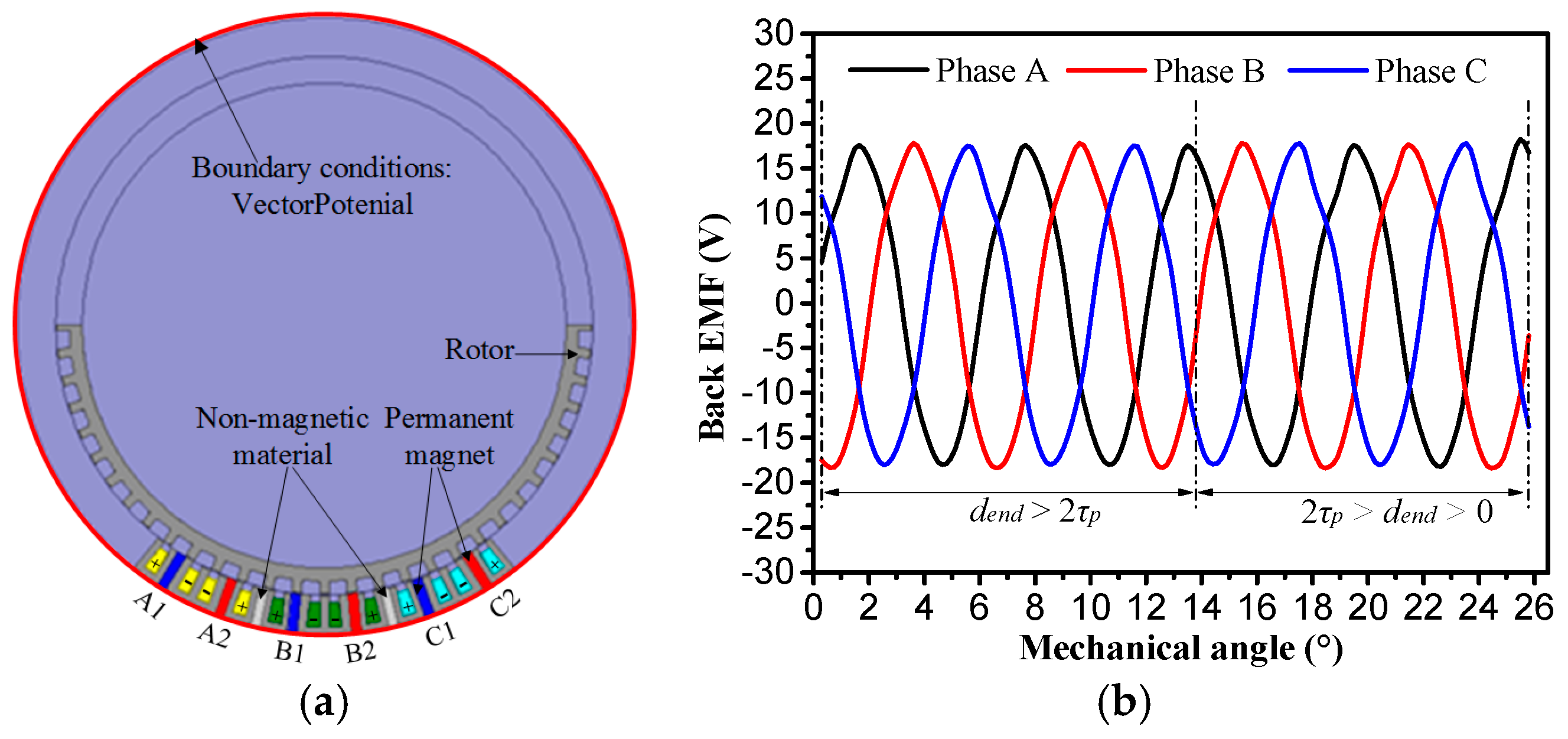
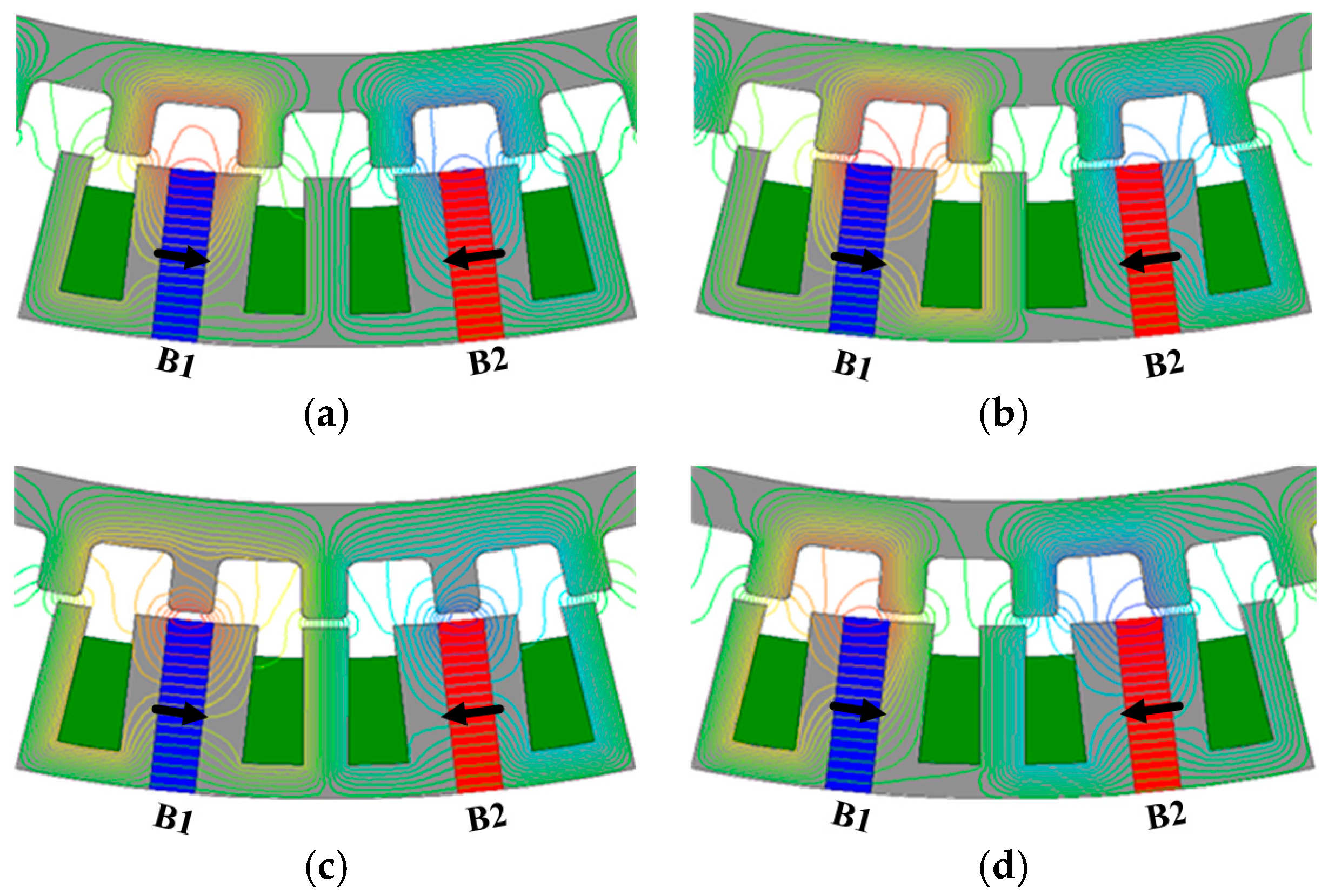
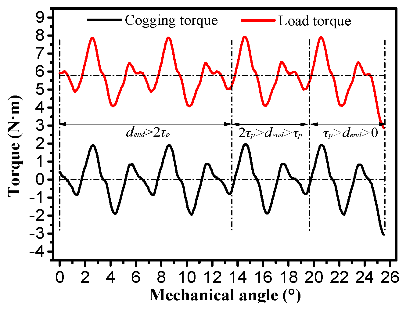
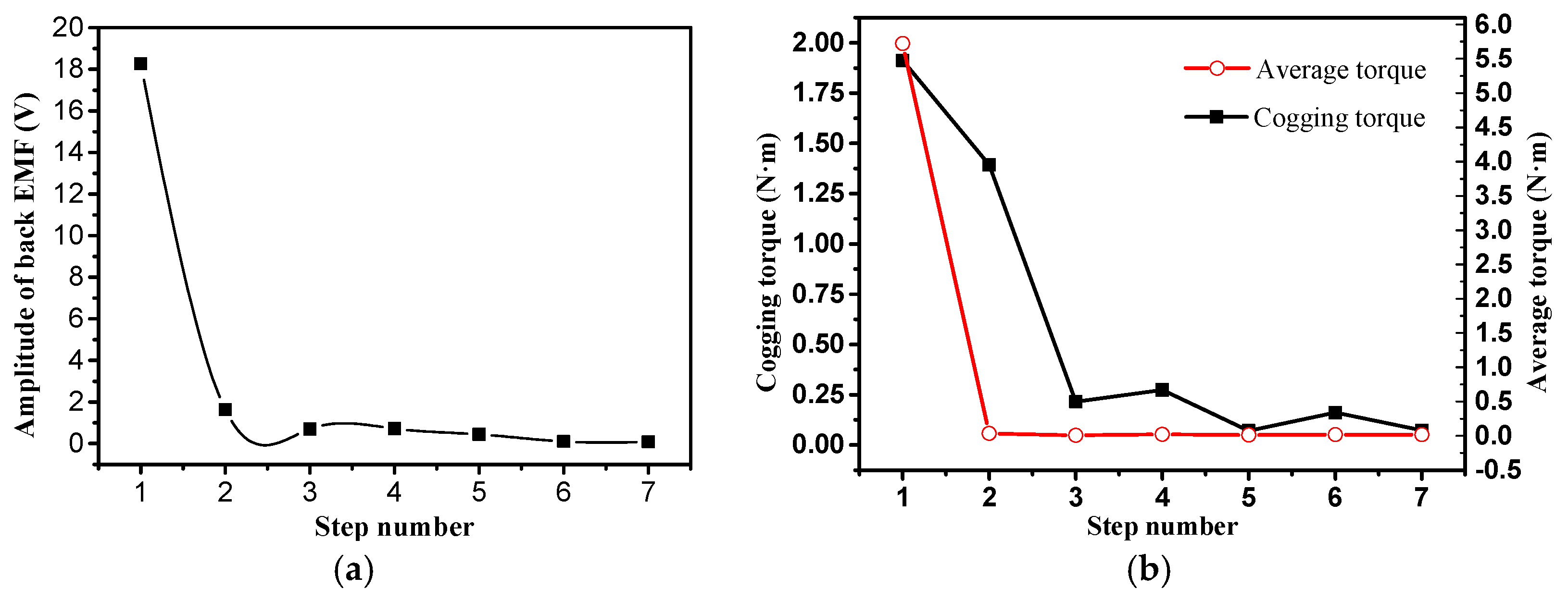
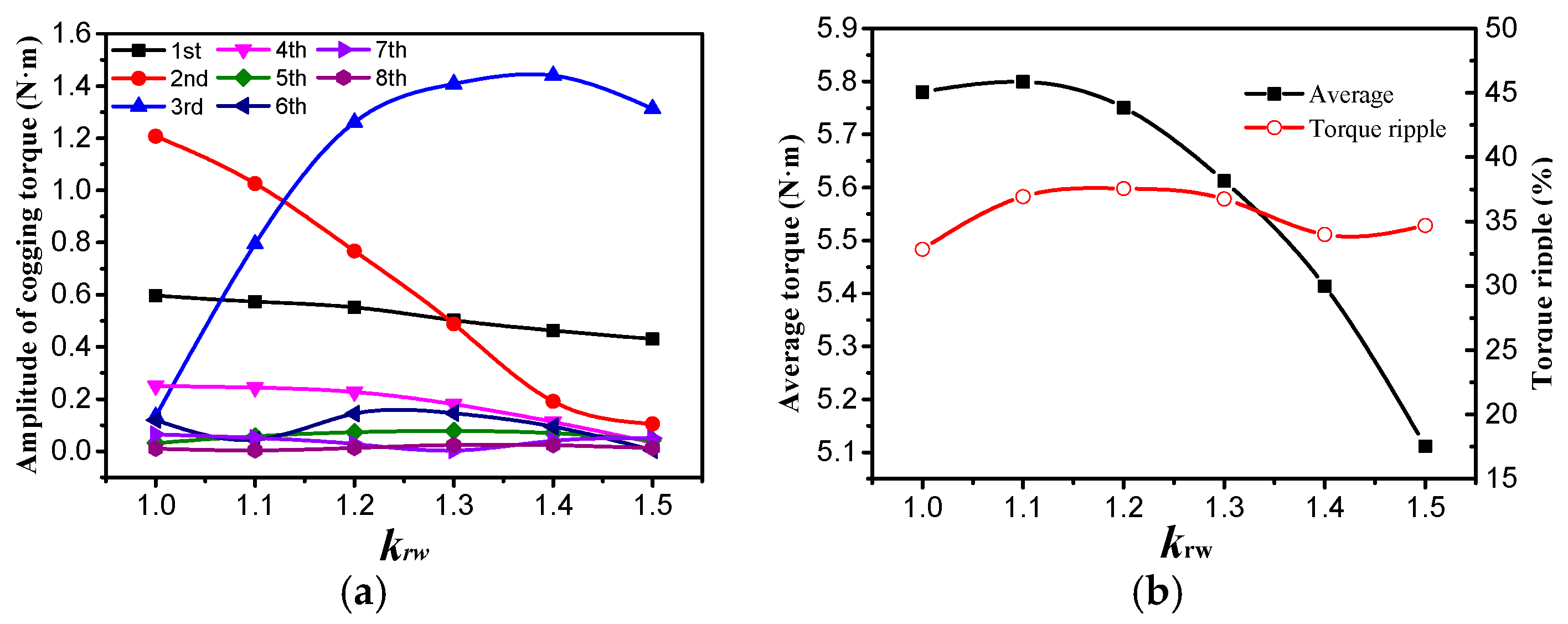
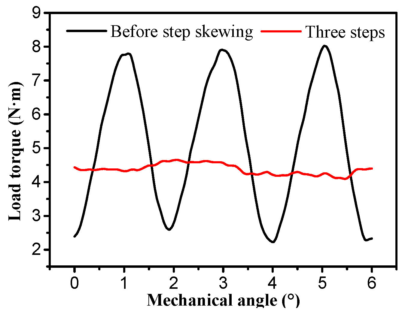
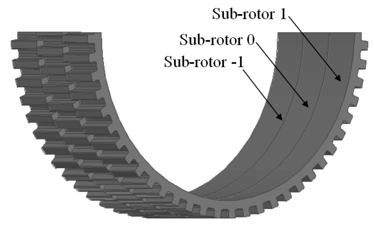
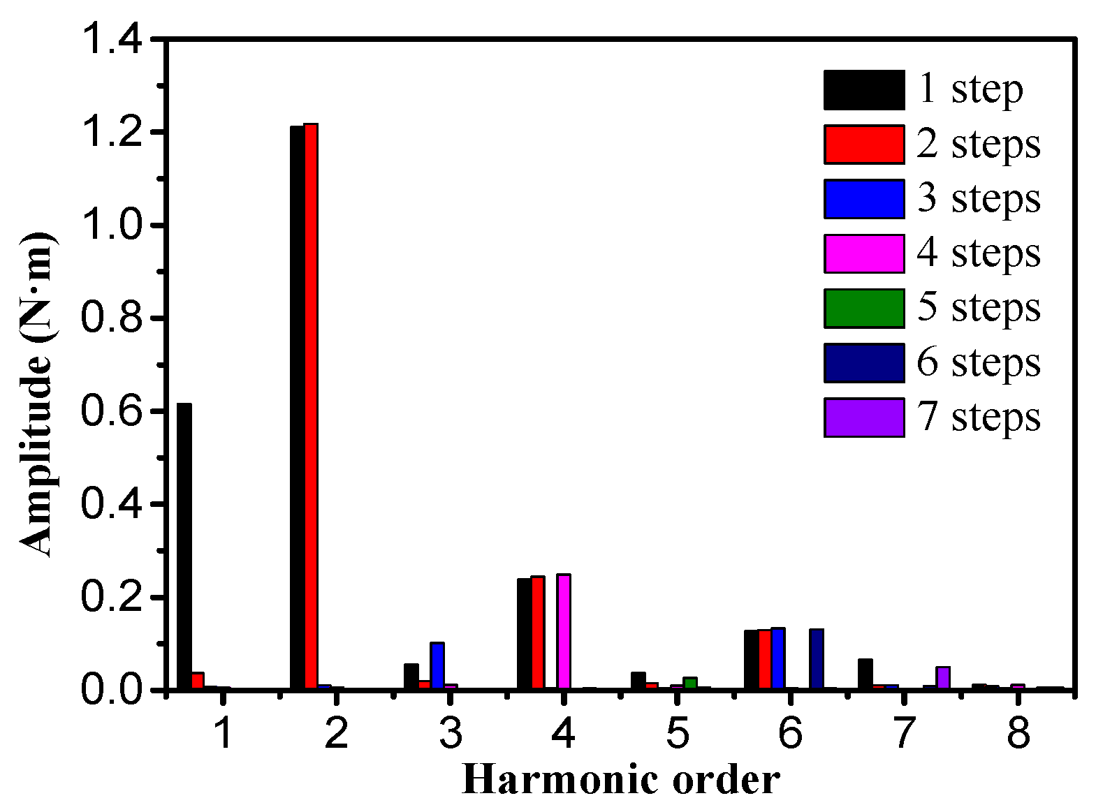
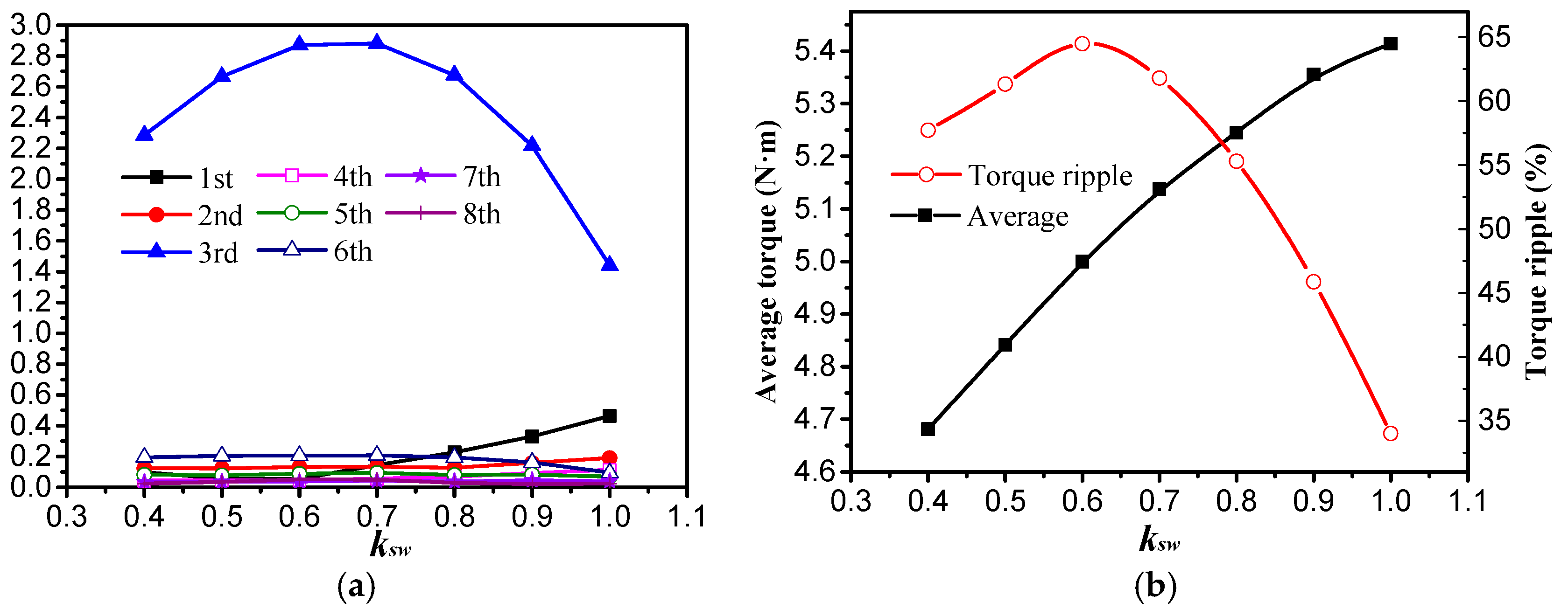
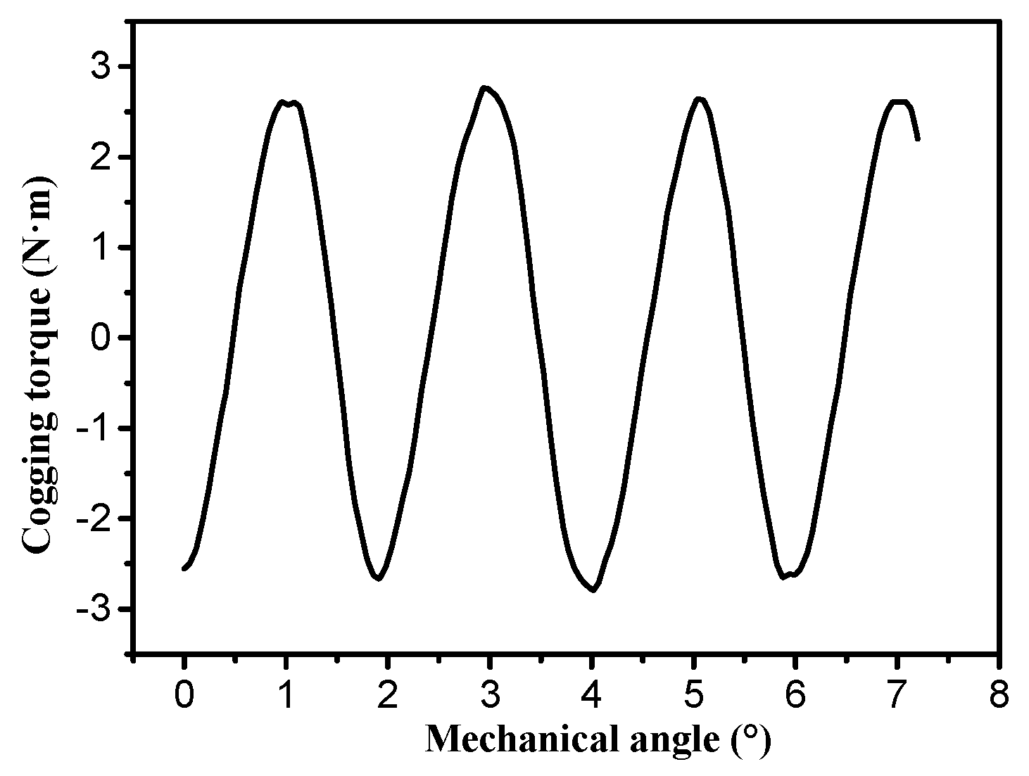
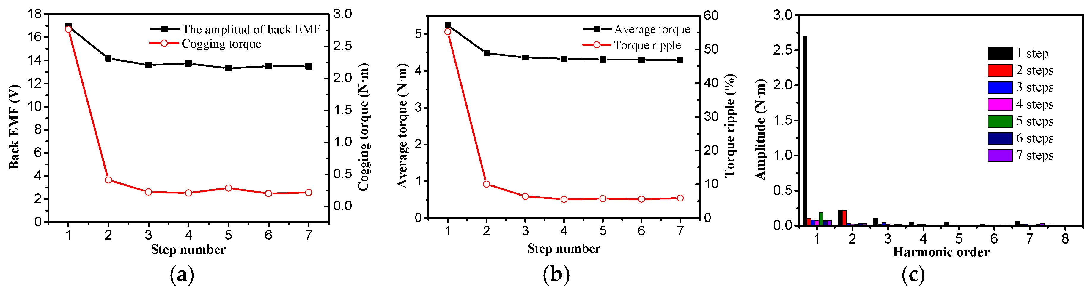
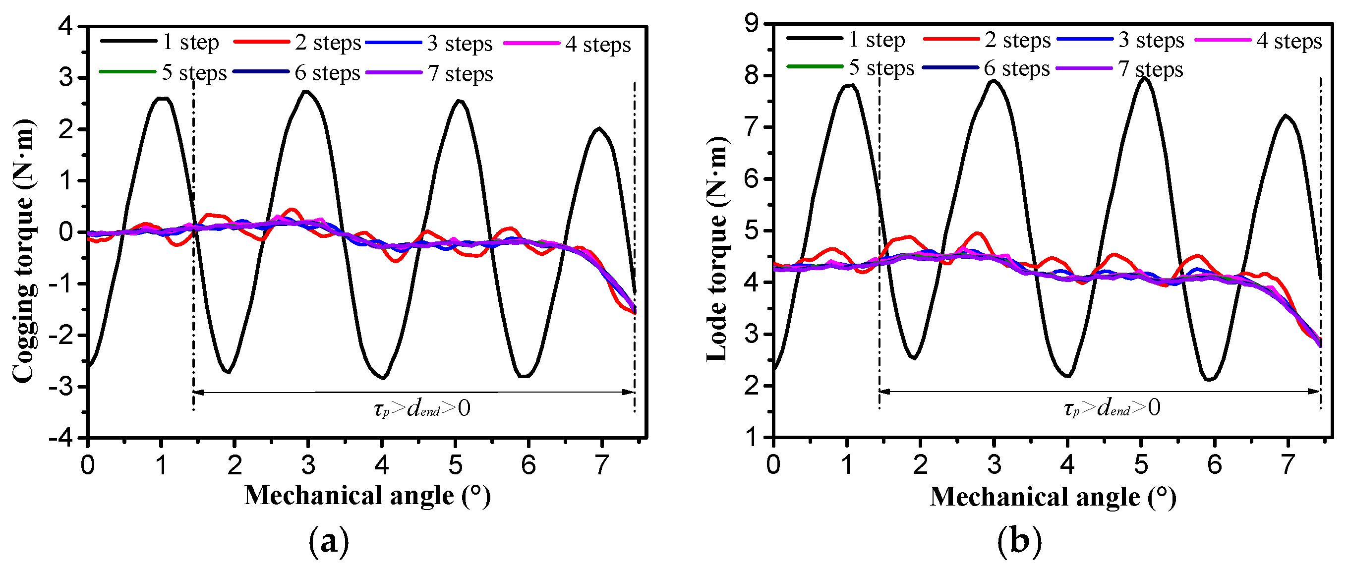
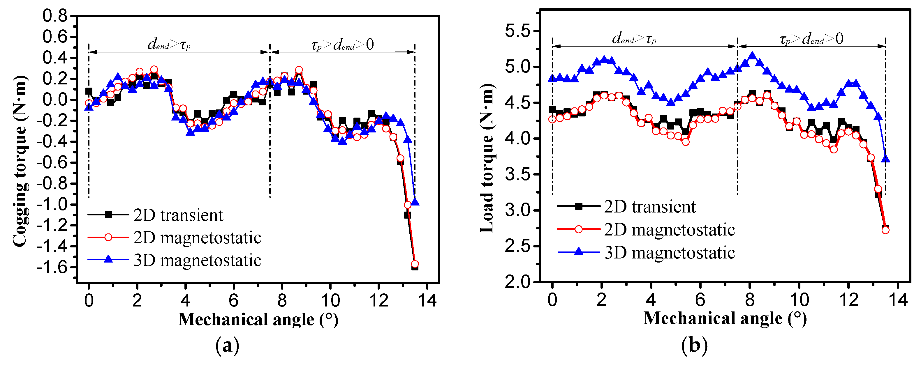
A novel modular AML-FSPM used for scanning system instead of reduction gearboxes and kinematic mechanisms is researched in this paper. Structure of the AML-FSPM is introduced and back EMF of the AML-FSPM is well balanced. Cogging toque model of the AML-FSPM is established based on end torque and slot torque. Furthermore, slot torque can be expressed by the sum of each stator module. Both the period of end torque and the period of slot torque are just one rotor tooth pitch of 6° (mechanical angle), which is the same as the period of the back EMF. Therefore, period ratio of cogging torque to the back EMF equals one. The characteristics of the cogging torque and torque ripple are investigated for both dend > 2τp and dend < 2τp. It shows that peak- peak cogging torque of dend < τp is bigger than that of dend > τp. Furthermore, the torque ripple is mainly caused by the cogging torque. The first harmonic, second harmonic, fourth harmonic and sixth harmonic are main components in the cogging torque. In order to reduce the cogging torque as much as possible and affect the back EMF as little as possible, influence of period ratio of cogging torque to the back EMF is investigated. It shows that bigger value of t is better. Therefore, rotor tooth width and stator slot open width are optimized to enhance third harmonic and restrain first and second harmonic. After optimization of rotor tooth width and slot open width, period ratio of cogging torque to back EMF is increased from 1 to 3. Then, step rotor skewing is adopted to reduce torque ripple. After the rotor three-step skewing, torque ripple is decreased from 32.9% to 6.4%, by 79.8%, for dend > τp, torque ripple is decreased from 45.1% to 22.7%, by 49.7%, for dend < τp when scanning rang is kept unchanged, and torque ripple will be within 6.4% during whole operation if left scanning range (θL) and right scanning range (θR) are reduced by 2°. Finally, the result obtained by 2D FEM is validated by 3D FEM.

Acknowledgments

This work was supported in part by the National Natural Science Foundation of China under Project 51307008, in part by the Key laboratory for Intelligent Control & Decision of Complex Systems of Beijing Institute of Technology, in part by Ph.D Programs Foundation of Ministry of Education of China under Project 20121101120024, and in part by Basic Research Foundation of Beijing Institute of Technology under Grant 20130642015.

Author Contributions

All authors contributed to this work by collaboration. Xiangdong Liu, Zhongxin Gu and Jing Zhao are the main authors of this manuscript and this work was conducted under the advisement of Jing Zhao. All authors revised and approved the publication.

Conflicts of Interest

The authors declare no conflict of interest.

References

  1. Mishra, A.K.; Kulkarni, A.N.; Moholkar, V.S. Automatic Leveling Mechanism for Weapon Systems Launching Platform Using Induction Motor. In Proceedings of the 2012 1st International Conference on Power and Energy in NERIST (ICPEN), Nirjuli, India, 28–29 December 2012; pp. 1–4.
  2. Pakdelian, S.; Deshpande, Y.; Toliyat, H.A. Design of an electric machine integrated with trans-rotary magnetic gear. IEEE Trans. Energy Convers. 2015, 30, 1180–1191. [Google Scholar] [CrossRef]
  3. Acampora, G.; Landi, C.; Luiso, M.; Pasquino, N. Optimization of Energy Consumption in a Railway Traction System. In Proceedings of the 2006 International Symposium on Power Electronics, Electrical Drives, Automation and Motion, Taormina, Italy, 23–26 May 2006; pp. 1121–1126.
  4. Xu, Q.W.; Cui, S.M.; Song, L.W.; Zhang, Q.F. Research on the power management strategy of hybrid electric vehicles based on electric variable transmissions. Energies 2014, 7, 934–960. [Google Scholar] [CrossRef]
  5. Saini, D.; Gaur, P. Control of 2-DOF Robotic Manipulator Using Brushless DC Motor to Track the Motion of Object in a Plane. In Proceedings of the 2012 IEEE 5th India International Conference on Power Electronics (IICPE), Delhi, Idia, 6–8 December 2012; pp. 1–4.
  6. Seo, J.M.; Rhyu, S.H.; Kim, J.H.; Choi, J.H.; Jung, I.S. Design of Axial Flux Permanent Magnet Brushless DC Motor for Robot Joint Module. In Proceedings of the 2010 International Power Electronics Conference (IPEC), Sapporo, Japan, 21–24 June 2010; pp. 1336–1340.
  7. Mishima, Y.; Ozawa, R. Design of a Robotic Finger Using Series Gear Chain Mechanisms. In Proceedings of the 2014 IEEE/RSJ International Conference on Intelligent Robots and Systems (IROS 2014), Chicago, IL, USA, 14–18 September 2014; pp. 2898–2903.
  8. Koganezawa, K.; Ishizuka, Y. Novel Mechanism of Artificial Finger Using Double Planetary Gear System. In Proceedings of the 2008 IEEE/RSJ International Conference on Intelligent Robots and Systems (IROS 2008), Nice, France, 22–26 September 2008; pp. 3184–3191.
  9. Bianchini, C.; Immovilli, F.; Bellini, A.; Mignano, P. Arc Linear Motors for Direct Drive Robots: Galileo Sphere. In Proceedings of the 2008 IEEE Industry Applications Society Annual Meeting, Edmonton, AB, Canada, 22–26 September 2008; pp. 1–7.
  10. Leonardi, F.; Venturini, M.; Vismara, A. PM motors for direct driving optical telescope. IEEE Ind. Appl. Mag. 1996, 2, 10–16. [Google Scholar] [CrossRef]
  11. Hua, W.; Zhu, Z.Q.; Cheng, M.; Pang, Y.; Howe, D. Comparison of Flux-Switching and Doubly-Salient Permanent Magnet Brushless Machines. In Proceedings of the Eighth International Conference on Electrical Machines and Systems (ICEMS 2005), Nanjing, China, 27–29 September 2005; pp. 165–170.
  12. Yi, D.; Chau, K.T.; Cheng, M.; Ying, F.; Wang, Y.B.; Hua, W.; Wang, Z. Design and analysis of linear stator permanent magnet vernier machines. IEEE Trans. Mag. 2011, 47, 4219–4222. [Google Scholar]
  13. Deodhar, R.P.; Andersson, S.; Boldea, I.; Miller, T.J.E. The flux-reversal machine: a new brushless doubly-salient permanent-magnet machine. IEEE Trans. Ind. Appl. 1997, 33, 925–934. [Google Scholar] [CrossRef]
  14. Zhu, X.Y.; Quan, L.; Chen, Y.Y.; Liu, G.H.; Shen, Y.; Liu, H. Permanent magnet online magnetization performance analysis of a flux mnemonic double salient motor using an improved hysteresis model. J. Appl. Phys. 2012, 111. [Google Scholar] [CrossRef]
  15. Zhu, X.Y.; Cheng, M.; Zhao, W.X.; Liu, C.H.; Chau, K.T. A transient cosimulation approach to performance analysis of hybrid excited doubly salient machine considering indirect field-circuit coupling. IEEE Trans. Mag. 2007, 43, 2558–2560. [Google Scholar] [CrossRef] [Green Version]
  16. Hua, W.; Chen, M.; Zhu, Z.Q.; Howe, D. Analysis and optimization of back EMF waveform of a flux-switching permanent magnet motor. IEEE Trans. Energy Convers. 2008, 23, 727–733. [Google Scholar] [CrossRef]
  17. Zhao, W.X.; Cheng, M.; Hua, W.; Jia, H.Y.; Cao, R.W. Back-EMF harmonic analysis and fault-tolerant control of flux-switching permanent-magnet machine with redundancy. IEEE Trans. Ind. Electron. 2011, 58, 1926–1935. [Google Scholar] [CrossRef]
  18. Chen, J.T.; Zhu, Z.Q. Comparison of all- and alternate-poles-wound flux-switching PM machines having different stator and rotor pole numbers. IEEE Trans. Ind. Appl. 2010, 46, 1406–1415. [Google Scholar] [CrossRef]
  19. Chang, J.J.; Ma, W.L.; Huang, J.L. Design and optimization of arc permanent magnet synchronous motor used on large telescope. IEEE Trans. Mag. 2012, 48, 1943–1947. [Google Scholar]
  20. Chen, J.T.; Zhu, Z.Q. Winding configurations and optimal stator and rotor pole combination of flux-switching PM brushless AC machines. IEEE Trans. Energy Convers. 2010, 25, 293–302. [Google Scholar] [CrossRef]
  21. Zhu, Z.Q.; Chen, J.T.; Pang, Y.; Howe, D.; Iwasaki, S.; Deodhar, R. Analysis of a novel multi-tooth flux-switching PM brushless AC machine for high torque direct-drive applications. IEEE Trans. Mag. 2008, 4, 4313–4316. [Google Scholar] [CrossRef]
  22. Cai, J.J.; Lu, Q.F.; Jin, Y.; Chen, C.Y.; Ye, Y.Y. Performance Investigation of Multi-Tooth Flux-Switching PM Linear Motor. In Proceedings of the 2011 International Conference on Electrical Machines and Systems (ICEMS), Beijing, China, 20–23 August 2011; pp. 1–6.
  23. Zhao, J.; Yan, Y.S.; Li, B.; Li, X.D.; Chen, Z. Influence of different rotor teeth shapes on the performance of flux switching permanent magnet machines used for electric vehicles. Energies 2014, 7, 8056–8075. [Google Scholar] [CrossRef]
  24. Abdollahi, S.E.; Vaez-Zadeh, S. Reducing cogging torque in flux switching motors with segmented rotor. IEEE Trans. Mag. 2013, 49, 5304–5309. [Google Scholar] [CrossRef]
  25. Wang, D.H.; Wang, X.H.; Jung, S.Y. Reduction on cogging torque in flux-switching permanent magnet machine by teeth notching schemes. IEEE Trans. Mag. 2012, 48, 4228–4231. [Google Scholar] [CrossRef]
  26. Wang, C.F.; Shen, J.X.; Wang, Y.; Wang, L.L.; Jin, M.J. A new method for reduction of detent force in permanent magnet flux-switching linear motors. IEEE Trans. Mag. 2009, 5, 2843–2846. [Google Scholar] [CrossRef]
  27. Fei, W.Z.; Luk, P.C.K.; Shen, J.X. Torque analysis of permanent-magnet flux switching machines with rotor step skewing. IEEE Trans. Mag. 2012, 48, 2664–2673. [Google Scholar] [CrossRef] [Green Version]
Figure 1. Galileo sphere robot.
Energies 09 00404 g001
Figure 2. The 3D structure of the arc-linear permanent-magnet motor (AL-PMSM).
Energies 09 00404 g002
Figure 3. (a) The structure of the modular arc-linear flux-switching permanent-magnet motor (MAL-FSPM); and (b) connection form of each phase windings.
Energies 09 00404 g003
Figure 4. (a) Finite element method (FEM) model of the MAL-FSPM; and (b) back electromotive force (EMF) of the MAL-FSPM.
Energies 09 00404 g004
Figure 5. The non-load magnetic field distribution of the module MB for: (a) position θ1; (b) position θ2; (c) position θ3; and (d) position θ4.
Energies 09 00404 g005
Figure 6. (a) Flux linkage waveforms of coil B1, coil B2 and phase B; and (b) back EMF and current waveforms (from top to bottom).
Energies 09 00404 g006
Figure 7. The no-load cogging torque and load torque curves.
Energies 09 00404 g007
Figure 8. Harmonic analysis of cogging torque.
Energies 09 00404 g008
Figure 9. Example for rotor step skewing of three.
Energies 09 00404 g009
Figure 10. The phase relationship of sub-motors: (a) step skewing number is even; and (b) step skewing number is odd.
Energies 09 00404 g010
Figure 11. The relationship among SkewVν,N, N and t.
Energies 09 00404 g011
Figure 12. Increase of step skewing number: (a) amplitude of back EMF; and (b) average torque and maximum value of cogging torque.
Energies 09 00404 g012
Figure 13. Relationship between cogging torque harmonic and step number.
Energies 09 00404 g013
Figure 14. Influence of krw: (a) cogging torque harmonics; and (b) average torque and torque ripple.
Energies 09 00404 g014
Figure 15. Slot open width adjustment.
Energies 09 00404 g015
Figure 16. Increase of ksw: (a) the cogging torque harmonics; and (b) average torque and torque ripple.
Energies 09 00404 g016
Figure 17. Cogging torque curve at ksw = 0.8.
Energies 09 00404 g017
Figure 18. Increase of step skewing number: (a) amplitude of back EMF and cogging torque; (b) average torque and torque ripple; and (c) cogging torque harmonics.
Energies 09 00404 g018
Figure 19. Load torque of before and after rotor step skewing.
Energies 09 00404 g019
Figure 20. (a) Cogging torque; and (b) load torque.
Energies 09 00404 g020
Figure 21. (a) Cogging torque; and (b) load torque.
Energies 09 00404 g021
Table 1. Main dimension parameters of each module.
ParametersValuesParametersValues
Rotor tooth height (mm)5Each module width (°)24
Motor length (mm)65Non-magnetic material width (°)2
Stator outer diameter (mm)240Slot width ts (°)2
Air-gap length (mm)0.75Tooth width of “U“ type (°)1.5
Rotor tooth width tr (°)2Tooth width of “E“ type (°)2
Rotor tooth pitch τp (°)6Phase number3
Magnet thickness tPM (°)2Rated speed (r/min)100
Magnet height (mm)15Amplitude of rated current (A)2.26
Chamfering radius Rtop (mm)0.6Chamfering radius Rroot (mm)1
Table 2. Torque performance of the MAL-FSPM.
Range of dendMaximum Torque (N·m)Minimum Torque (N·m)Average Torque (N·m)Torque Ripple (%)
dend > 2τp7.884.085.7832.9
p > dend > τp7.934.095.8332.9
τp > dend > 07.902.875.5845.1
Table 3. The step number and skewing angle of the MAL-FSPM.
Step Number234567
Aall (°)180240270288300308.6
An (°)18012090726051.4
Mechanical degree for An (°)321.51.210.86
Table 4. Step number and skewing angle.
Step Number234567
Aall (°)180240270288300308.6
An (°)18012090726051.4
Mechanical degree for An (°)10.670.50.40.330.29
Table 5. Torque characteristics for τp > dend >0.
Parameter1 Step2 Steps3 Steps4 Steps5 Steps6 Steps7 Steps
Peak-peak cogging (N·m)5.572.041.871.991.861.871.87
Average torque (N·m)4.984.264.144.134.094.084.07
Ripple (%)58.724.222.724.423.022.922.9
Table 6. Characteristics of torque for dend > τp.
Parameters2D Transient2D Magnetostatic3D Magnetostatic
Peak-peak cogging (N·m)0.450.550.52
Peak-peak load torque (N·m)0.560.650.6
Average torque (N·m)4.374.324.82
Torque ripple (%)6.47.56.2
Table 7. Characteristics of torque for τp > dend > 0.
Parameters2D Transient2D Magnetostatic3D Magnetostatic
Peak-peak cogging torque(N·m)1.871.861.11
Peak-peak load torque (N·m)1.871.881.43
Average torque (N·m)4.144.084.65
Torque ripple (%)22.723.015.5

