Article

A Multi-Period Framework for Coordinated Dispatch of Plug-in Electric Vehicles

1
College of Electrical Engineering, Zhejiang University, Hangzhou 310027, China
2
School of Information Technology and Electrical Engineering, The University of Queensland, Brisbane 4067, Australia
3
State Grid Zhejiang Electric Power Company, Hangzhou 310007, China
*
Author to whom correspondence should be addressed.
Energies 2016, 9(5), 370; https://doi.org/10.3390/en9050370
Submission received: 31 January 2016 / Revised: 9 May 2016 / Accepted: 10 May 2016 / Published: 16 May 2016

Abstract

:
Coordinated dispatch of plug-in electric vehicles (PEVs) with renewable energies has been proposed in recent years. However, it is difficult to achieve effective PEV dispatch with a win-win result, which not only optimizes power system operation, but also satisfies the requirements of PEV owners. In this paper, a multi-period PEV dispatch framework, combining day-ahead dispatch with real-time dispatch, is proposed. On the one hand, the day-ahead dispatch is used to make full use of wind power and minimize the fluctuation of total power in the distribution system, and schedule the charging/discharging power of PEV stations for each period. On the other hand, the real-time dispatch arranges individual PEVs to meet the charging/discharging power demands of PEV stations given by the day-ahead dispatch. To reduce the dimensions of the resulting large-scale, non-convex problem, PEVs are clustered according to their travel information. An interval optimization model is introduced to obtain the problem solution of the day-ahead dispatch. For the real-time dispatch, a priority-ordering method is developed to satisfy the requirements of PEV owners with fast response. Numerical studies demonstrate the effectiveness of the presented framework.

1. Introduction

The real-time balance of power generation and load is the basis for maintaining power system security and stability. In traditional power systems, uncertainty was usually caused by stochastic load fluctuations, unexpected forced outages, etc., however, with the increasing public awareness of environmental problems, there appeared a sustained growth penetration of renewable energies. Their inherent volatility and uncertainty brought challenges to power system operation and planning [1]. It has become difficult to continue to use the traditional methods for maintaining balance of power generation tracking load fluctuation. With the advent of controllable loads, new controllable load tracking renewable energy modes are expected to be widely applied.
In the initial stage of plug-in electric vehicle (PEV) development, their disordered charging produced significant negative impacts on power system operation, such as distribution network losses [2], voltage level [3], three-phase load balance [4], transformer life [5] problems and so on. In fact, PEVs can share some similar characteristics with energy storage units, and for most PEVs, the time period when they could be connected to PEV charging stations is much longer than their required charging time [6]. Therefore, the selection of PEVs’ charging time is relatively flexible, and PEVs can also be discharged moderately. Some research indicates that PEVs’ charging/discharging dispatch can not only reduce their negative impacts, but also help to ensure more secure and economic operation of power systems. Reference [7] proposes a technique to dispatch charging of PEVs to minimize their effect on the distribution system assets. In [8,9], methodologies are proposed to minimize energy losses by utilizing smart charging and discharging of PEVs. A novel layered and distributed framework is proposed for PEV dispatch to minimize the generation cost in [10], with stochastic wind power considered. A bidirectional charging control is proposed in [11] to manage power balance. Price competitive interactions between PEV charging stations and renewable power generations are analyzed in [12]. PEVs are adopted to improve energy quality in [13,14], and the proposed methods are capable of managing voltage and primary frequency, respectively. However, the above studies all depend on the premise that PEV owners are willing to participate in the dispatch. In the current stage, price signals might be adopted to attract PEV owners, but what they care about more is whether their travel demands can be satisfied firstly.
From the perspective of dispatch period, coordinated PEV dispatch can be divided into day-ahead dispatch [9,10,15,16] and real-time dispatch [11,14,17]. Day-ahead dispatch is obtained in a 24 h dispatch horizon based on predicted values of uncertain parameters. It can tolerate relatively long computation times, which can be suitable for obtaining a 24 h large-scale PEV dispatch plan. Nevertheless, accurate travel demands and plug-in information for a specific PEV cannot be well predicted in a day-ahead period, so it is quite difficult for the day-ahead dispatch to satisfy the requirements of individual PEV owners. In the real-time dispatch, each individual PEV is arranged based on their real-time conditions. Thus, by appropriate charging/discharging dispatch, PEVs’ travel demands could be satisfied when they unplug from charging stations. However, there still exist some problems. Firstly, due to the huge number of PEVs, it is difficult to assign charging/discharging behavior for each individual PEV with fast enough response for the real-time dispatch. Furthermore, the real-time dispatch always only focuses on its current period, but does not take the situations of prior periods or later periods into consideration, and thus is lacking a full picture. Multi-period dispatch combined with day-ahead dispatch and real-time dispatch could be a feasible solution to deal with the questions above, and has already been proposed in several studies [18,19], mainly for large-scale integration of renewable energies. On one hand, the day-ahead dispatch is used to obtain a 24 h horizon schedule for renewable energy integration. On the other hand, the real-time dispatch deals with the day-ahead prediction errors. In this paper, a framework for multi-period PEV dispatch is proposed to achieve a comprehensive system dispatch in the day-ahead period and satisfy each individual PEV’s travel demands in the real-time period.
Travel behavior of PEVs and wind power generation are both affected by many factors, which lead to their inherent uncertainty. In the present studies, wind power and PEVs’ uncertainty are usually described by assumed distributions, such as the Weibull distribution [20] or the multivariate normal distribution [21], and some optimization algorithms like probabilistic power flow [22] or cross entropy methods [23] are used for solving the stochastic optimization problems. However in fact, although their expected value and standard deviation could be estimated by certain means, no specific distribution can accurately describe their fluctuation and uncertainty. Nevertheless, it is much easier to obtain their distribution intervals accurately from some certain estimation techniques and system operators’ experiences. In this paper, predictive distribution intervals are used to describe the uncertainty of wind power and PEVs, and interval optimization algorithm is adopted to solve the day-ahead dispatch model. As for the real-time dispatch, a priority-ordering method is proposed to obtain appropriate dispatch in fast response with PEV owners’ requirements satisfied.
The main contributions of this paper are summarized below:
  • An integrated framework for multi-period PEV dispatch which pursues a win-win result for both the power system and PEV owners is proposed.
  • Interval optimization is adopted in the day-ahead dispatch.
  • A PEV-clustered model and a priority-ordering method are proposed to support the multi-period PEV dispatch.
The remainder of this paper is organized as follows: in Section 2, the framework for the multi-period PEV dispatch is developed. The problem formulations are presented in Section 3. Section 4 introduces the methods for solving the proposed models. Numerical studies are presented in Section 5. Finally, Section 6 concludes the paper.

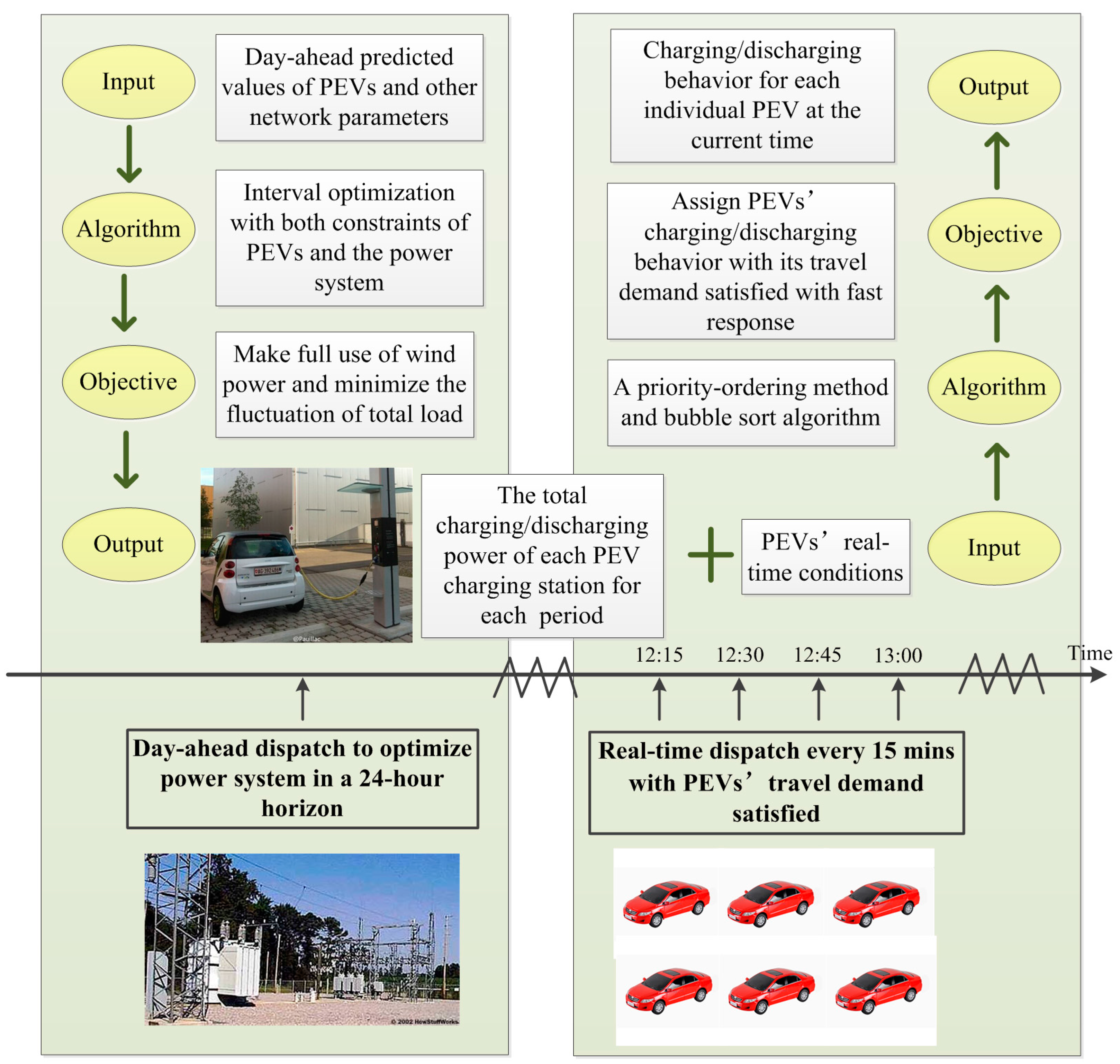
2. The Proposed Multi-Period Dispatch Framework

As mentioned above, the day-ahead dispatch and the real-time dispatch have their own characteristics. In this paper, the day-ahead dispatch with a 24 h dispatch horizon and the real-time dispatch with PEV owners’ requirements satisfied are combined reasonably in the proposed framework, i.e., dispatch pursuing a win-win result for both the power system and PEVs is obtained. The proposed multi-period PEV dispatch framework is shown in Figure 1.
High-penetration wind power in the power system is difficult to utilize due to its inherent uncertainty and excessive output during traditional load off-peak periods [24]. Therefore, in this work, the objective of the day-ahead dispatch is to make full use of high-penetration wind power and minimize the total load fluctuation in the distribution system in a 24 h dispatch horizon. PEVs are dispatched to charge in the period of wind power generation peaks or traditional load valleys, and vice versa, to discharge moderately. The day-ahead dispatch schedules the charging/discharging power of PEV stations for each period. It is also gives the instructions followed by the real-time dispatch for assigning each individual PEV.
In the real-time period, each individual PEV connected to charging stations is dispatched to achieve the day-ahead plan. The real-time dispatch aims at strictly following the charging/discharging power demands of PEV charging stations from the day-ahead dispatch. A key point of the real-time dispatch is that the requirement of each individual PEV should be satisfied.
Each specific PEV has its unique travel demand and plug-in information. To satisfy the requirements of PEV owners, it’s necessary to know such information before the real-time dispatch. PEVs’ plug-in information like plug-in time Tplug-in, battery charging/discharging types Type and required charging time tev could all be scanned and obtained by the operator when they are plugging into PEV charging stations. However, it is different for their expected plug-out information. In order to satisfy the requirements of PEV owners, a manual demand reporting mode is needed. Once a PEV plugs into a charging station, its owner is required to provide its expected plug-out information, which includes the plug-out time Tplug-out and expected state of charge ESOC.
It is worth noting that interval optimization is adopted in the day-ahead dispatch, and it can help guarantee the day-ahead dispatch is an executable one. As long as the day-ahead predictive intervals of uncertain parameters cover the real-time actual values, there exist appropriate charging/discharging assignments for each individual PEV in the real-time dispatch to achieve the day-ahead plan.
In addition, before the charging/discharging dispatch formulation and execution, some PEVs which do not meet the dispatch constraints should be removed. For example, if the required charging time of a PEV is longer than the time period it connects to the charging station, or a PEV owner does not voluntarily participate in the dispatch, that PEV should be removed from the coordinated dispatch.

3. Problem Formulations

3.1. The Day-Ahead Plug-In Electric Vehicles Model

Since the real-time dispatch follows the results of the day-ahead dispatch, to obtain an effective multi-period dispatch, it is necessary that the day-ahead dispatch be an executable one. To achieve that, an accurate day-ahead PEV prediction would be a prerequisite. For an individual PEV, its plug-in information and travel demand are affected by many factors, such as the owner’s intentions and traffic conditions. Its travel information can barely be well predicted in the day-ahead period. Fortunately, in contrast, the predictions of all PEVs’ travel information distribution are quite simple. If there are huge enough numbers of PEVs, like to typical day’s load distribution, a typical day’s PEV travel information distribution is relatively stable. Through statistical analysis, PEV travel information distributions of typical days with specific conditions (season, weather, etc.) can be obtained. Since travel requirements of PEV owners are similar to those of normal vehicle owners, the American National Household Travel Survey (NHTS) [6] was selected as the authoritative source to characterize the typical day PEV travel information distribution in this work, which includes the time when the first trip starts, the time when the last trip ends, and daily travel mileage. The plug-in time Tplug-in (when the last trip ends) and plug-out time Tplug-out (when the first trip starts) are modeled with normal distributions, and the daily travel mileage is modeled with a logarithmic normal distribution [25]. Fitting results are displayed in Equations (1)–(3). The required charging time tev is shown in Equation (4). Besides, it is worth mentioning that the validity of the proposed multi-period dispatch relies on accurate predictions. Therefore, if this multi-period framework is utilized in reality, the day-ahead PEV distributions should be modeled through statistical analysis based on real data. The proposed framework and optimization algorithm are generic to the PEV models, irrelevant of the assumed distributions:
f plug-in ( x ) = { 1 σ in 2 π exp ( ( x + 24 μ in ) 2 2 σ in 2 )    0 < x μ in 12 1 σ in 2 π exp ( ( x μ in ) 2 2 σ in 2 )     μ in 12 < x 24
where μin and σin are fitting parameters. μin = 17.6, σin = 3.4.
f plug-out ( x ) = { 1 σ out 2 π exp ( ( x μ out ) 2 2 σ out 2 )     0 < x μ out + 12 1 σ out 2 π exp ( ( x 24 μ out ) 2 2 σ out 2 )    μ out + 12 < x 24
where μout and σout are fitting parameters. μout = 9.24, σout = 3.16.
f d ( x ) = 1 x σ d 2 π exp ( ( ln x μ d ) 2 2 σ d 2 )
where μd and σd are fitting parameters. μd = 3.2, σd = 0.88.
t ev = d W 100 100 p ch η ch
where W100 is PEVs’ electric usage per 100 km; pch is the charging power of an individual PEV; ηch is PEVs’ average charging efficiency.
It is worth emphasizing that accurate predictions of all PEVs’ travel information distribution are quite different from those of individual PEVs. In the day-ahead dispatch, none of the PEVs are identified. The results of the day-ahead dispatch are the charging/discharging power of each PEV station for each period, without consideration of any specified PEV.

3.2. The PEV-Clustered Model

Due to the rapid development of PEVs, their number could be very large in the future. For either day-ahead or real-time period, the dispatch model could become technically intractable due to the high dimensionality of the problem. The main idea of the PEV-clustered model is to aggregate PEVs with similar travel information into a plug-in electric vehicle aggregator (PEVA). To simplify the model, the number of PEVs in each PEVA is set identical.
In the day-ahead dispatch, for PEVs’ predicted travel information, the clustering criterions mainly include their battery charging/discharging types Type, plug-in time Tplug-in, required charging time tev (or remaining quantity of electricity), plug-out time Tplug-out and expected state of charge ESOC. PEVs with all these parameters similar are clustered into one PEVA. They will be considered as an integrated variable in the day-ahead dispatch model.
The charging power intervals of PEVAs without coordinated dispatch are obtained by a Monte Carlo sampling according to Equations (1)–(4). Through sampling the plug-in time Tplug-in and required charging time tev of PEVs 10,000 times, a PEVA’s charging power’s expectation μ(t) and variance σ2(t) can be obtained. Charging power interval of a PEVA without coordinated dispatch is described as [μ(t) – γ × σ(t), μ(t) + γ × σ(t)] in this work. Fluctuation factor γ can be set by system operators. A higher γ corresponding with a higher confidence level would lead to an interval covering more real-time PEVs. It is worth mentioning that different γ can be selected for different PEVAs in practical dispatch. In this paper, a unified γ is selected for simplification. If there are no special instructions, γ is selected as 3 with the corresponding 99.7% confidence level. To simplify the model, discharging power of PEVs is assumed similar to charging power, without battery self-discharge into consideration. The specific discharging power intervals are not detailed.

3.3. The Day-Ahead Dispatch Model

Wind power is predicted to have high penetration in the power system in the near future. However, its generation peak period is always at midnight, which does not match with the peak period of traditional loads [24]. In order to avoid wind power curtailing, in the day-ahead dispatch, PEVs are dispatched to charge in the period of wind power generation peak or traditional load valley, and vice versa, to discharge moderately. The objective of the day-ahead dispatch model in this work is to make full use of wind power and minimize the fluctuation of total power in the distribution system:
F obj = t = 1 24 ( P L , t + P ev , t P w , t t = 1 24 ( P L , t + P ev , t P w , t ) / 24 ) 2
where:
P L , t = j = 1 n P L , j , t
P ev , t = j = 1 n P ev , j , t
P w , t = j = 1 n P w , j , t
where PL,j,t, Pev,j,t and Pw,j,t represent day-ahead predicted intervals of traditional load, PEV charging power and wind power generation at bus j at time t, respectively, and n represents the number of distribution buses.
In this paper, intervals are used to describe the uncertain parameters of the distribution system, and interval optimization algorithm is adopted to solve the day-ahead dispatch model. Mathematically, an interval optimization problem can be formulated as Equations (9)–(11). Some specific introduction of the interval optimization algorithm is detailed in [26]:
min    f ( X , U )
s.t.    g i ( X , U ) = [ b i l , b i r ]
g i ( X , U ) [ c i l , c i r ]
where U is the decision vector; X is input interval vector; [bil, bir] is the ith equality interval constraint; [cil, cir] is the ith inequality interval constraint. In the day-ahead dispatch, the decision vector U represents the charging/discharging behavior of PEVs. It is noteworthy that it’s not an interval vector. Each PEV station’s charging/discharging power demand for each period is then obtained according to the dispatched PEVs’ charging/discharging behavior.
To make sure it can be an executable dispatch, both constraints of the distribution system [27] and PEVs [25] should be taken into consideration.
(1)
Power flow equality constraints:
{ P j k , t V j , t k = 1 n V k , t ( G j k cos θ j k , t + B j k sin θ j k , t ) = 0 Q j k , t V j , t k = 1 n V k , t ( G j k sin θ j k , t B j k cos θ j k , t ) = 0
where Pjk,t and Qjk,t represent the active and reactive power intervals of branch jk at time t, respectively. Vj,t and Vk,t represent the voltage magnitude intervals of bus j and k at time t. Gjk and Bjk are the real part and imaginary part of the nodal admittance matrix. θjk,t is the phase angle deviation interval of branch jk.
(2)
Apparent power constrains for distribution lines:
P j k , t P j k max
where Pjkmax is the maximum power value interval of branch jk.
(3)
Bus voltage constraints:
V j min V j , t V j max
where Vjmin and Vjmax are the minimum and maximum voltage magnitude intervals at bus j, respectively.
(4)
Charging/discharging power constraints for PEVs:
0 p ch , t p ch max × ξ ch , t
0 p dch , t p dch max × ξ dch , t
where pch,t and pdch,t are charging and discharging power of individual PEVs at time t. pchmax and pdchmax are their maximum values. ξch,t and ξdch,t are binary variables for the identification flag of PEVs’ charging and discharging state at time t. For example, ξch,t = 1 represents that it is in a charging state at time t.
(5)
Complementary constrains of charging/discharging states:
ξ ch , t + ξ dch , t 1
(6)
Charging/discharging quantity equality constraints:
S O C ev , t + 1 = S O C ev , t + p ch , t × η ch p dch , t η dch
where SOCev,t is the state of charge of PEVs at time t. ηch and ηdch are PEVs’ average charging and discharging efficiency, respectively.
(7)
Capacity constraints for PEV’s batteries:
S O C ev min S O C ev , t S O C ev max
where SOCevmin and SOCevmax are the minimum and maximum state of charge of PEVs, respectively.
(8)
Travel demand constraints:
S O C ev , t plug-out E S O C
where SOCev,tplug-out is PEVs’ state of charge when they plug out of PEV charging stations.

3.4. The Real-Time Dispatch Model

The real-time dispatch aims at following charging/discharging power demand of each PEV station at the current time obtained from the day-ahead dispatch. Each individual PEV connected to charging stations is dispatched to achieve the day-ahead plan. The objective is to minimize the dispatching deviation between the day-ahead dispatched power demands and real-time realized power of each PEV charging station:
min    j = 1 n [ ( P ch , j , t P ch , j , t ) 2 + ( P dch , j , t P dch , j , t ) 2 ]
where:
P ch , j , t = m = 1 m ch . j , t p ch , j , t
P dch , j , t = m = 1 m dch . j , t p dch , j , t
where Pch,j,t and Pdch,j,t represent the day-ahead dispatched charging/discharging power demands of PEV stations at bus j at the current time t. Pch,j,t and Pdch,j,t represent the real-time realized charging/discharging power of PEV stations at bus j at the current time t. pch,j,t and pdch,j,t are charging and discharging power of individual PEVs at bus j at time t. mch,j,t and mdch,j,t are the number of PEVs charging/discharging at bus j at the current time t.
Since all constraints of the distribution system have already been considered in the day-ahead dispatch, if the real-time dispatch strictly follows the results from the day-ahead dispatch, it is not necessary to consider these constraints again. Safety of power system operation could be guaranteed. To meet the constraints of PEVs and satisfy the requirements of PEV owners, a priority-ordering method is proposed.

3.5. The Priority-Ordering Method

In the real-time dispatch, conditions of PEVs connected to charging stations are changing all the time. In addition to Type, Tplug-in, tev, Tplug-out and ESOC, there is another specific parameter of PEVs: their updated required charging time tev, which represents their real-time updated conditions. In this context, its evolutive parameter is proposed to be a significant index in the real-time dispatch: the updated surplus time (UST) Tplug-out + 24 − ttev, where t is the current time. UST represents the real-time idle degree of PEVs. A longer UST indicates that PEVs are idler, and the selection of their charging time is more flexible. Furthermore, even if they discharge to a certain degree, they will still have enough time to finish recharging before they plug out of PEV charging stations. Therefore, in this work, PEVs with a longer UST are set to have a lower charging priority but a higher discharging priority, and vice versa. In the real-time dispatch, PEVs’ charging/discharging behavior is assigned according to their UST. The main process of the real-time dispatch for a PEV charging station is as follows:
  • The total charging power demand Pch,j,t or discharging power demand Pdch,j,t of the PEV charging station at the current time is obtained from the day-ahead dispatch;
  • scan PEVs connected to the certain charging station at the current time, and cluster them into PEVAs according to their UST;
  • if charging power Pch,j,t is required to achieve the day-ahead plan, set PEVAs to charge at their rated charging power from the one with the lowest level of UST; then, gradually upgrade the UST level, until meeting the requirement of the total charging power Pch,j,t;
  • else, set PEVAs to discharge from the one with the highest level of UST; then, gradually degrade the UST level, until meeting the requirement of the total discharging power Pdch,j,t.
By adopting the proposed priority-ordering method, it is not difficult to conclude that constraints of PEVs Equations (15)–(18) could all be met. Furthermore, as mentioned above, before the charging/discharging dispatch formulation and execution, PEVs which do not meet the dispatch constraints should be removed, which makes it possible that all PEVs to be dispatched in the real-time dispatch could meet the PEV capacity constraint Equation (19). As for constraint Equation (20), since the day-ahead is an executable one, there exists a corresponding real-time dispatch which could achieve the day-ahead plan while satisfying individual PEVs’ travel demands. The priority-ordering method enables the PEVs with the longest required charging time to charge first, which can satisfy PEV owners’ requirements as much as possible. Moreover, since interval optimization is adopted in day-ahead dispatch, it supplies a certain margin for the real-time dispatch. It is worth mentioning that there is some non-zero probability that a non-executable dispatch is obtained in the day-ahead period. If inaccurate predictions of load, wind power or PEVs are adopted in the day-ahead dispatch, i.e., if at least one prediction interval could not cover their actual values in real-time period, it may result in non-optimal dispatch, or even contingencies. The premise of executable day-ahead dispatch is accurate predictions and appropriate choice of intervals. If the day-ahead dispatch turns out to be non-executable in real-time period, some additional auxiliary means should be utilized, such as the application of energy storage.

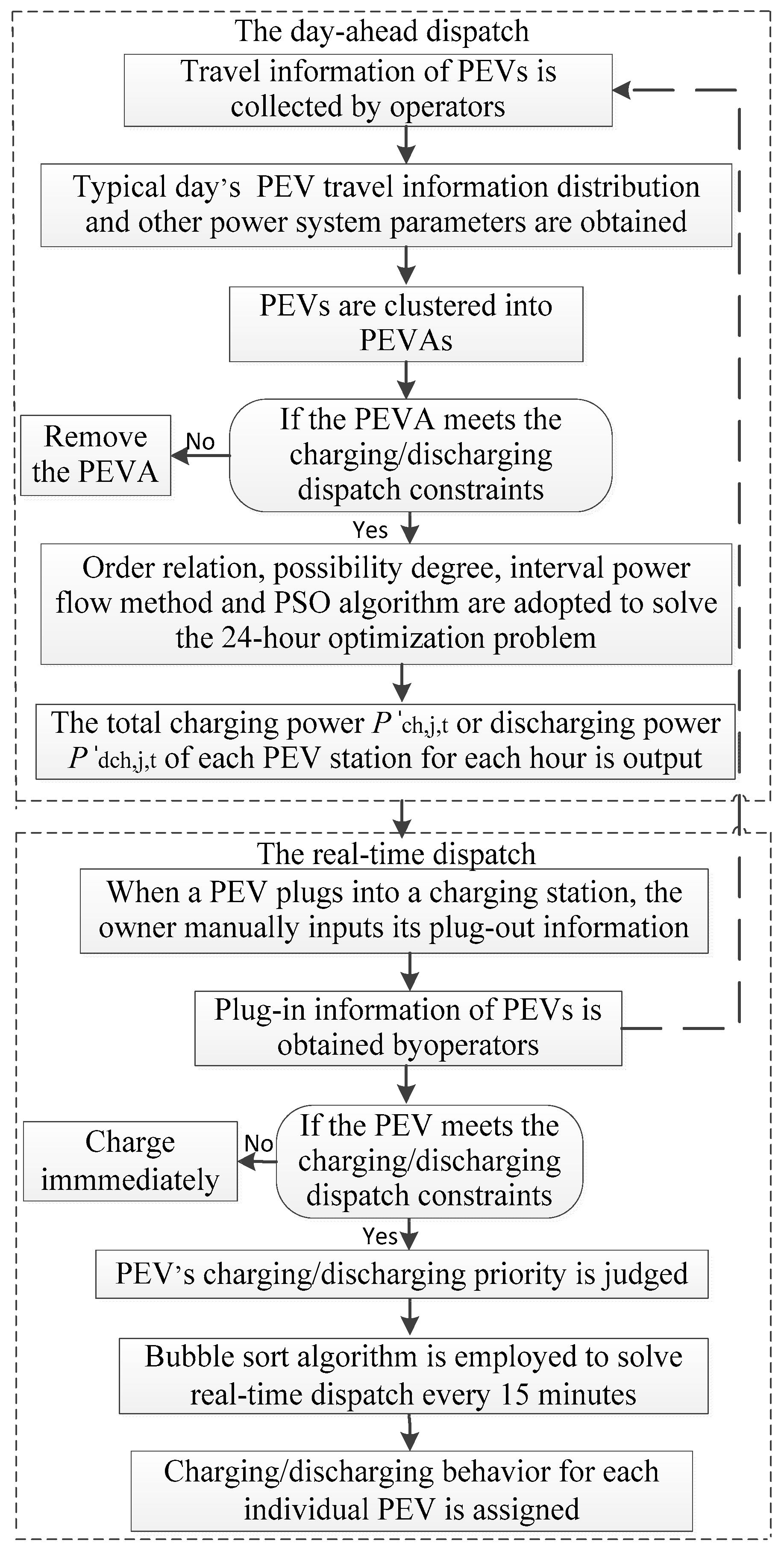
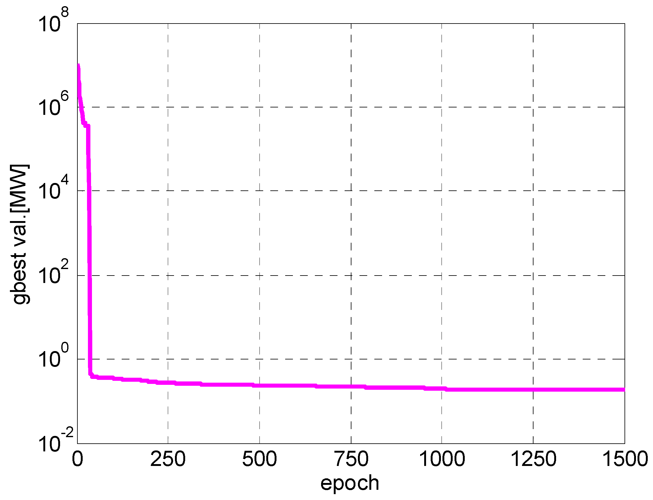
4. Approach for Solving the Proposed Models

The day-ahead dispatch model is an interval optimization problem. This kind of uncertain optimization problem is always transformed into a deterministic optimization for solving. This paper adopts the methods described in [28]. Firstly, the objective function is converted based on order relation. Weighted sum of the midpoint and radius is set as the equivalent objective function. Secondly, by adopting possibility degree, interval constraints are converted to equivalent deterministic constraints. As for the interval power flow algorithm, a back/forward sweep method for interval distribution network power flow [29] is adopted in this work. Finally, PSO algorithm is employed to solve the converted deterministic day-ahead dispatch model. The convergence criterion is the variation of two adjacent iterations less than ε or the number of iterations reaches n. As to the real-time dispatch, it is essentially a sequencing problem. A bubble sort algorithm is employed to solve it. The flow for solving the multi-time dispatch models is shown in Figure 2.

5. Case Studies and Discussion

5.1. Case Description

A modified IEEE 33-bus testing distribution system is employed to demonstrate the effectiveness of the proposed multi-time PEV dispatch method. The reference voltage of the network is 12.66 kV, three-phase power reference is 10 MVA, and its topology and data can be found in [30]. This modified testing system contains four PEV charging stations and their relevant information is listed in Table 1. PEVs’ electric usage per 100 km for type A and B are respectively 12 kWh and 10 kWh, and their charging/discharging power is 3.6 kW and 3 kW, respectively. Wind power generations are added in bus 16 and 28, and their reference powers are respectively 900 kW and 1100 kW. The midpoint daily variations of traditional load and wind power generation are shown in Figure 3. Settings of other crucial parameters are shown in Table 2. ω represents the day-ahead predicted ratio of radius to midpoint of wind power generation, and ω‘ represents its uncertain range in reality. γ represents the day-ahead predicted fluctuation factor of PEV charging power, and γ’ represents the real-time one. α represents the ratio of the standard error to the expected value of traditional loads. PEVs’ ESOC could vary in reality, 90% is set in this work. Other travel information of PEVs in real-time period, namely plug-in time, plug-out time and daily travel mileage, is generated by Monto Carlo simulation from the assumed distributions in Equations (1)–(3).

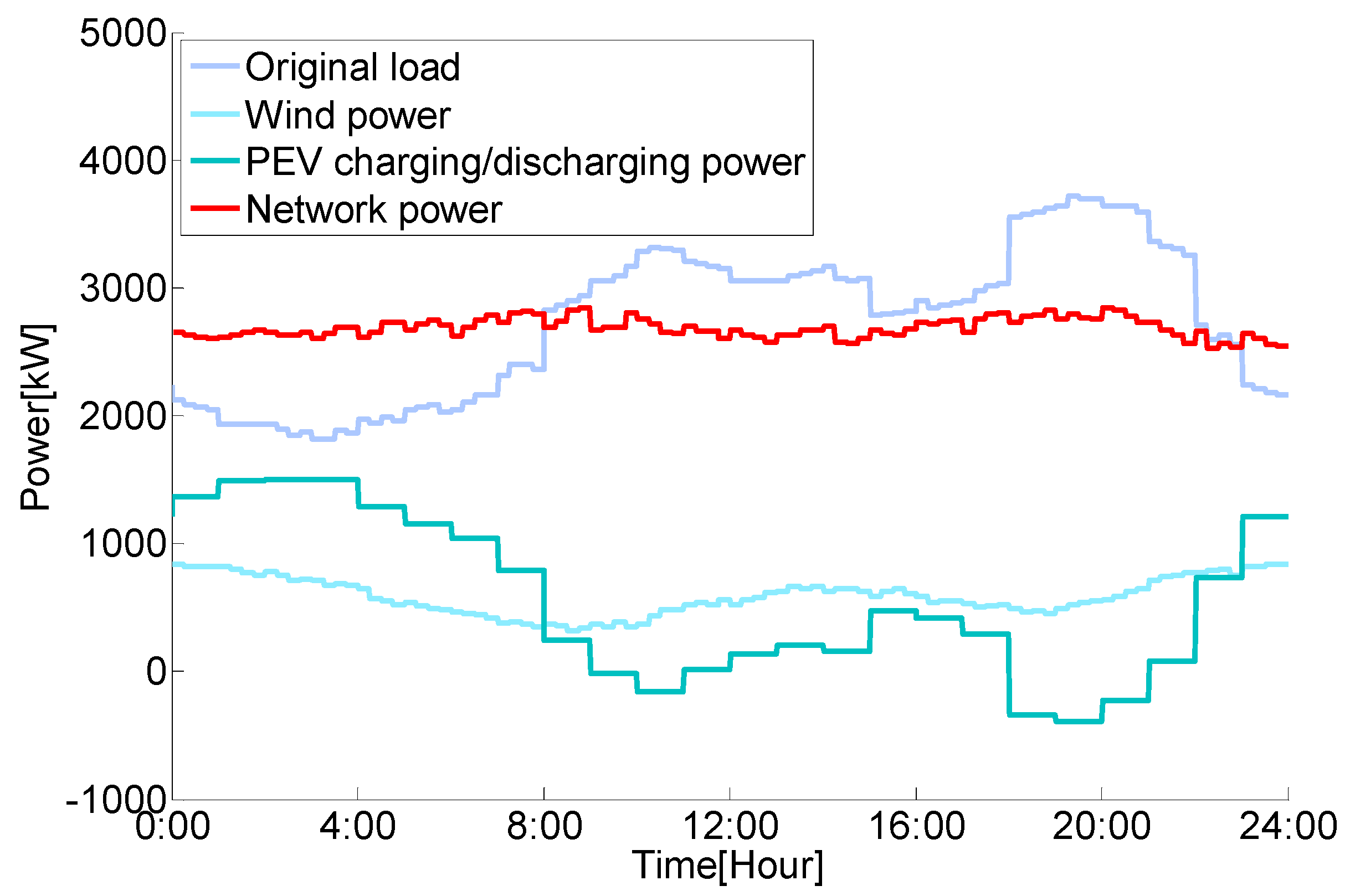
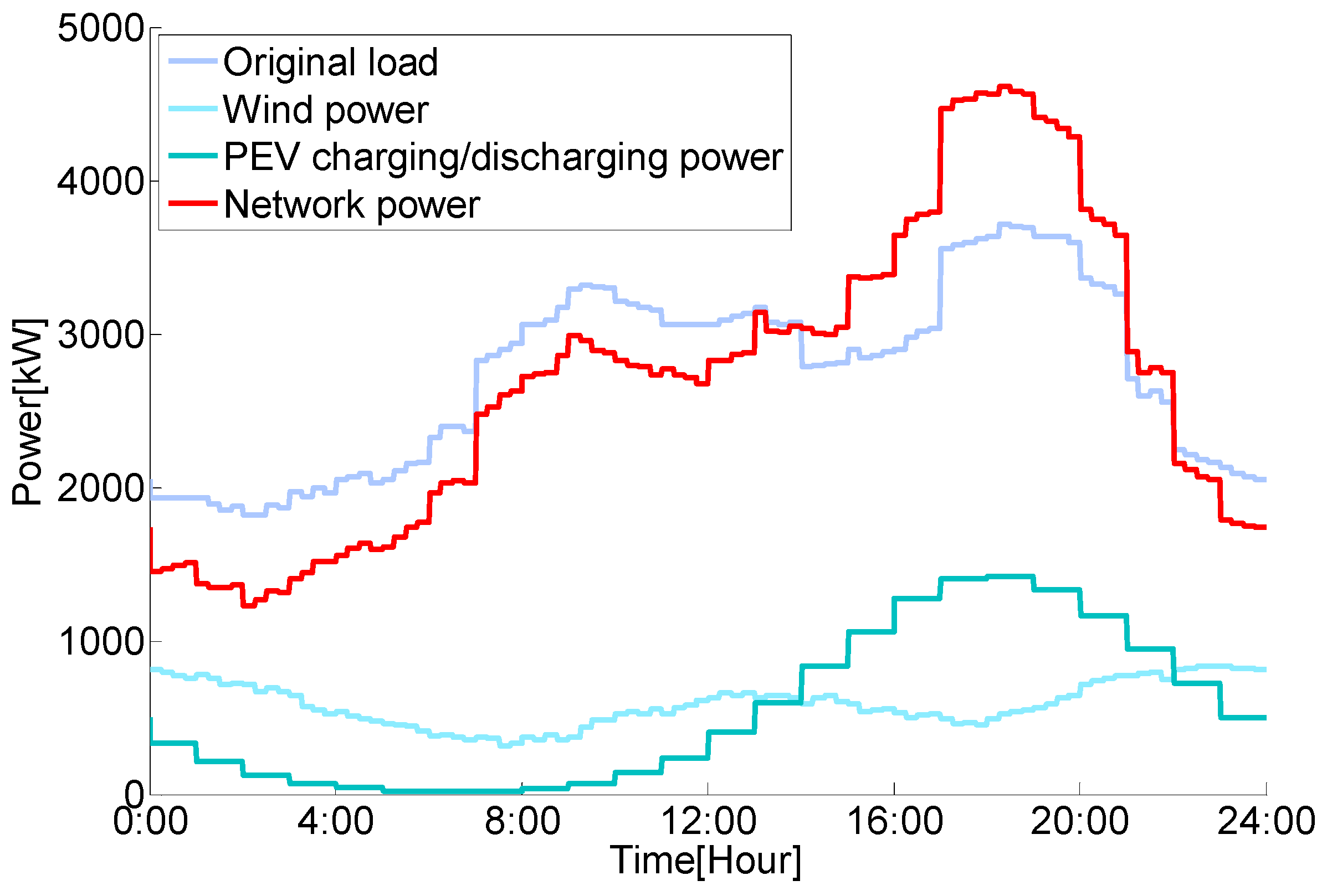
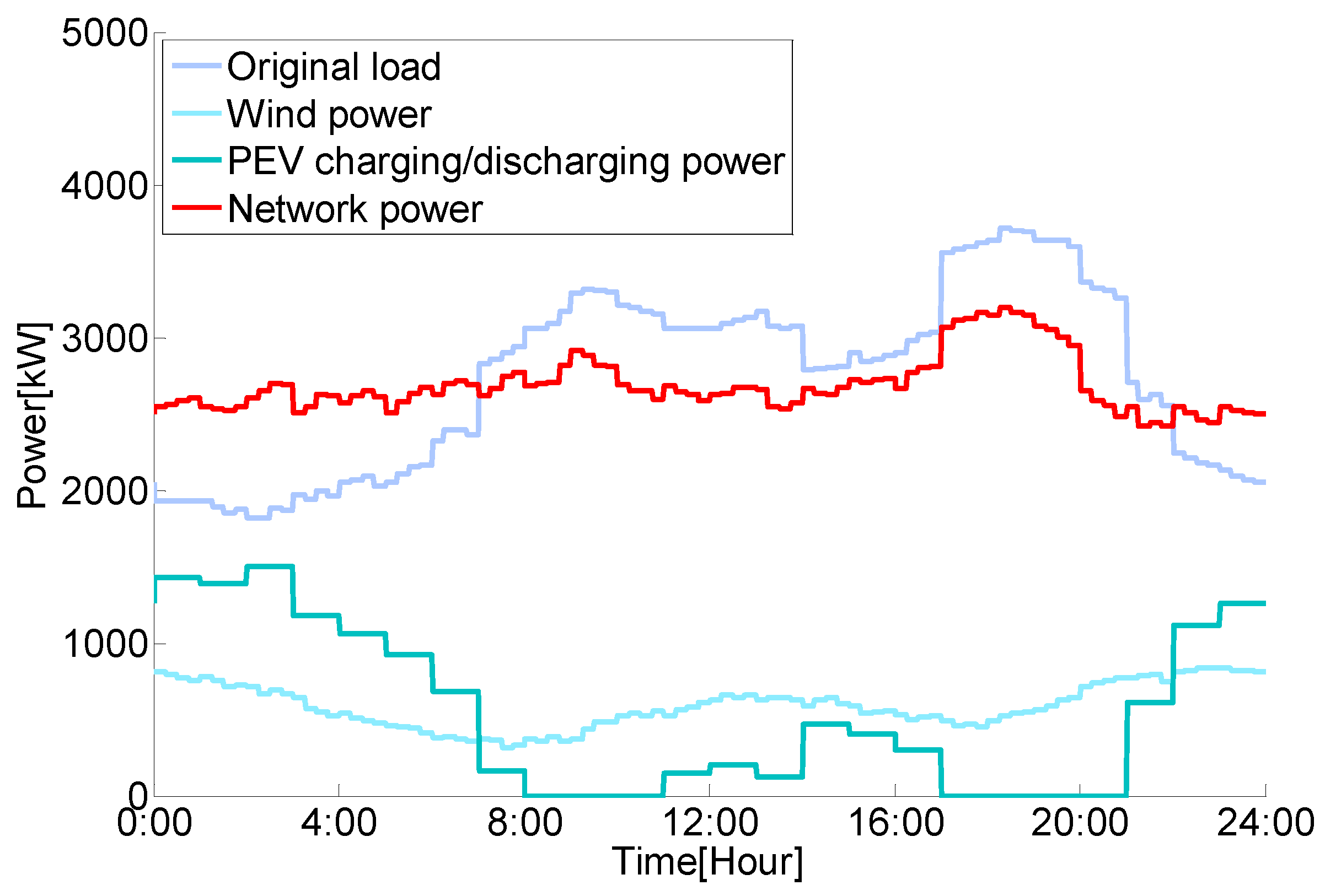
5.2. The Performance of the Multi-Period Dispatch

The significance of employing the coordinated PEV dispatch is to mitigate the negative impacts brought by PEVs’ disordered charging and make full use of wind power in the distribution system. Three different modes are compared to reflect the effectiveness of the proposed multi-period PEV dispatch, and their results are displayed in Figure 3, Figure 4 and Figure 5, respectively.
In uncoordinated mode, PEVs are not participating in any dispatch, and they would charge immediately when they finish their trips and be plugged into PEV charging stations. Due to the lack of prevention available with traditional load peaks and reasonable utilization of wind power, uncoordinated PEV charging will aggravate the differences between the peaks and valleys of the total load in the distribution system, which will further result in higher operation costs. In coordinated charging mode, PEVs are dispatched in coordination, thus their disordered charging negative impacts are largely mitigated. However, PEVs’ discharging function is not applied in this mode. In the coordinated charging/discharging mode, PEVs’ degree of idling is taken into consideration. Idle PEVs are discharged within an appropriate level to make better use of wind power generation. It is not difficult to conclude from Figure 3, Figure 4 and Figure 5 that wind power is better utilized with PEVs’ coordinated dispatch and they have an even better performance with consideration of PEVs’ discharging function.
Besides power system operation, PEV owners’ requirements are also considered in the proposed multi-period dispatch. Based on accurate day-ahead predictions and appropriate choice of intervals, day-ahead prediction intervals would be able to cover the actual values in the real-time period most of the time, therefore the robustness of the dispatch model is almost guaranteed. Furthermore, due to the validity of the proposed priority-ordering method in the real-time dispatch, in this case study, up to 99.85% of PEVs reach their ESOC when they plug out of charging stations, which almost meets PEV owners’ prerequisite to participate in the coordinated PEV dispatch.
In the proposed multi-time PEV dispatch, the PEV-clustered model is adopted in both the day-ahead period and real-time period to reduce the dimensions of the dispatch model. Apparently, an elaborate clustering plan with a large cluster number will result in better optimization performance, and a coarse clustering plan will improve response speed. The contrasts of cluster number, optimization performance and response speed are presented in Table 3. Since an interval optimization algorithm is adopted in the day-ahead dispatch to deal with the uncertainty, it takes a relatively long computation time. A plot of how the day-ahead objective function value reduces as the iterations increase for case No. 2 is displayed in Figure 6, with a total computation time about 40 min. Fortunately, the computation burden is not the major concern of the day-ahead dispatch. On the contrary, as to the real-time dispatch, response time is an important index. It should only take a short time for the real-time dispatch to assign charging/discharging behavior for each individual PEV. In practical application, an appropriate cluster number should be able to obtain a satisfactory optimization within acceptable computation time.
In order to show the performance of the multi-period dispatch and the coordination of PEVs and wind power, optimization results for several case scenarios are displayed in Table 4. In Scenarios 1–9, the integration levels of wind power and PEVs vary. It’s not easy to conclude from Table 4 how the objective value changes when the integration level of wind power or PEVs increase. A higher integration of PEVs might lead to more controllability, but it won’t work without a considerable amount of wind power. Overall, to obtain a relatively ideal optimization result, there needs to be an appropriate match between PEVs and available wind power.

5.3. Interval Optimization and the Uncertainty Level

PEVs’ demands can barely be accurately predicted in the day-ahead period. In the day-ahead dispatch, a proper uncertainty level should be included to represent this uncertainty. Optimizations under some different uncertainty levels are displayed in Table 5. Obviously, as PEV’s uncertainty levels increase, the objective value will be increased synchronously. Therefore, if the prediction accuracy in day-ahead period is improved, the performance of the proposed framework would be improved as well. However, what is worth paying attention to is that the uncertainty level adopted in the day-ahead dispatch must be consistent with the actual uncertainty. Otherwise, if a higher prediction accuracy is blindly adopted in the day-ahead dispatch, it will not only have nothing to do with improving the actual optimization performance, but may also lead to operation safety problems like exceeding the power flow.

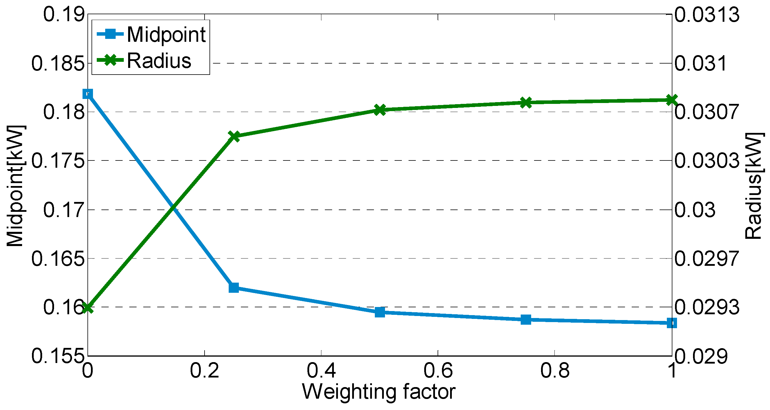
5.4. Sensitivity Analysis

In the interval optimization model, the objective function is converted based on order relation. Weighted sum of the midpoint and radius β × Fobjmid + (1 − β) × Fobjrad is set as the equivalent objective function. A sensitivity analysis, which studies the sensitivity of the weighting factor β with changes of the objective midpoint and radius value, is displayed in Figure 7. As is shown, the objective midpoint value reduces when the weighting factor β increases, however the radius increases. An appropriate β should be chosen in practical dispatch depending on the concern extent of a better mean value or better controllability. If system operators tend to favor a better mean value of objective function, a relatively high β should be chosen. On the other hand, a relatively low β will result in better controllability.

6. Conclusions

Coordinated dispatched PEVs can be a controllable load to optimize power system operation. However in the current stage, due to the lack of consideration on the requirements of PEV owners, PEV dispatch remains in a theoretical research phase, and is not applied widely in actual dispatch. Given this background, a multi-period coordinated PEV dispatch framework is presented.
By reasonably combining the day-ahead dispatch with the real-time dispatch, the multi-period PEV dispatch could obtain a win-win result for both the power system and PEV owners based on reliable day-ahead predictions. For power system operation, PEVs are dispatched to make full use of wind power and minimize the fluctuations of total load in the distribution system with a 24-h dispatch horizon. For PEV owners, since individual PEVs’ charging/discharging behavior is assigned in the real-time period according to its actual conditions, their travel demands could be satisfied as much as possible. If there price signal incentives were used, most PEV owners would likely participate in the dispatch.
In real-time dispatch, PEVs’ charging/discharging behavior is decided by their UST. Since their UST has continuity to a certain extent, there would not appear PEVs continuously changing between charging and discharging states. However, since the number of charging/discharging state transformation times for PEVs is not restricted, this still has some negative impacts on battery life. In future studies, PEVs’ battery life would be taken into consideration in a further step. In addition, if data sources were available, rolling dispatch could also be added into the multi-period dispatch, providing time-scale integrity. With the adoption of more accurate updated predictions, the performance of the multi-period PEV dispatch would also improve.

Acknowledgments

The work of Yinuo Huang, Chuangxin Guo and Yi Ding was supported in part by the State Key Program of National Natural Science Foundation of China (51537010) and in part by National Basic Research Program (973 Program) (2013CB228206).

Author Contributions

Yinuo Huang and Chuangxin Guo conceived and designed the experiments; Yinuo Huang and Licheng Wang performed the experience, analyzed the data. Yinuo Huang wrote the paper; Chuangxin Guo conceived the project, Yiding, Chuangxin Guo, Bingquan Zhu and Lizhong Xu reviewed and edited the manuscript. All authors read and approved the manuscript.

Conflicts of Interest

The authors declare no conflict of interest.

References

  1. Li, N.; Hedman, K.W.H. Economic assessment of energy storage in systems with high levels of renewable resources. IEEE Trans. Sustain. Energy 2015, 6, 1103–1111. [Google Scholar] [CrossRef]
  2. Jia, Y.R.; Ramachandaramurthy, V.K.; Kang, M.T. Modeling of electric vehicle fast charging station and impact on network voltage. In Proceedings of the IEEE Conference on Clean Energy and Technology (CEAT), Langkawi, Malaysia, 18–20 November 2013.
  3. Leou, R.C.; Su, C.L.; Lu, C.N. Stochastic analyses of electric vehicle charging impacts on distribution network. IEEE Trans. Power Syst. 2014, 29, 1055–1063. [Google Scholar] [CrossRef]
  4. Dharmakeerthi, C.H.; Mithulananthan, N.; Saha, T.K. Impact of electric vehicle load on power system oscillatory stability. In Proceedings of the Australasian Universities Power Engineering Conference (AUPEC), Hobart, Australia, 29 September–3 October 2013.
  5. Sexauer, J.M.; McBee, K.D.; Bloch, K.A. Applications of probability model to analyze the effects of electric vehicle chargers on distribution transformers. IEEE Trans. Power Syst. 2013, 28, 847–854. [Google Scholar] [CrossRef]
  6. Santos, A.; McGuckin, N.; Nakamoto, H.Y. Summary of Travel Trends: 2009 National Household Travel Survey; Rep.FHWA-PL-11022; U.S. Department of Transportation Federal Highway Administration: Washington, DC, USA, 2011.
  7. Aravinthan, V.; Jewell, W. Controlled electric vehicle charging for mitigating impacts on distribution assets. IEEE Trans. Smart Grid 2015, 6, 999–1099. [Google Scholar] [CrossRef]
  8. Xu, Y.L. Optimal distributed charging rate control of plug-in electric vehicles for demand management. IEEE Trans. Power Syst. 2015, 30, 1536–1545. [Google Scholar] [CrossRef]
  9. Nafisi, H.; Agah, S.M.M.; Abyaneh, H.A. Two-stage optimization method for energy loss minimization in microgrid based on smart power management scheme of PHEVs. IEEE Trans. Smart Grid 2016, 7, 1268–1276. [Google Scholar] [CrossRef]
  10. Shao, C.C.; Wang, X.F.; Wang, X.L. Layered and distributed charge load dispatch of considerable electric vehicles. IEEE Trans. Power Syst. 2015, 30, 1858–1867. [Google Scholar] [CrossRef]
  11. Liu, Z.; Wang, D.; Jia, H.J. Aggregation and bidirectional charging power control of plug-in hybrid electric vehicles: Generation system adequacy analysis. IEEE Trans. Sustain. Energy 2015, 6, 325–335. [Google Scholar] [CrossRef]
  12. Lee, W.; Xiang, L.; Schober, R. Electric vehicle charging stations with renewable power generators: A game theoretical analysis. IEEE Trans. Smart Grid 2015, 6, 608–617. [Google Scholar] [CrossRef]
  13. Cheng, L.; Chang, Y.; Huang, R. Mitigating voltage problem in distribution system with distributed solar generation using electric vehicles. IEEE Trans. Sustain. Energy 2015, 6, 1475–1484. [Google Scholar] [CrossRef]
  14. Izadkhast, S.; Garcia-Gonzalez, P.; Frias, P. An aggregate model of plug-in electric vehicles for primary frequency control. IEEE Trans. Power Syst. 2015, 30, 1475–1482. [Google Scholar] [CrossRef]
  15. Vayá, M.G.; Andersson, G. Optimal bidding strategy of a plug-in electric vehicle aggregator in day-ahead electricity markets under uncertainty. IEEE Trans. Power Syst. 2015, 30, 2375–2385. [Google Scholar] [CrossRef]
  16. Soares, J.; Morais, H.; Sousa, T. Day-ahead resource scheduling including demand response for electric vehicles. IEEE Trans. Smart Grid 2013, 4, 596–605. [Google Scholar] [CrossRef]
  17. Vagropoulos, S.I.; Kyriazidis, D.K.; Bakirtzis, A.G. Real-time charging management framework for electric vehicle aggregators in a market environment. IEEE Trans. Smart Grid 2016, 7, 948–957. [Google Scholar] [CrossRef]
  18. Gruber, J.K.; Huerta, F.; Matatagui, P. Advanced building energy management based on a two-stage receding horizon optimization. Appl. Energy 2015, 160, 194–205. [Google Scholar] [CrossRef]
  19. Wu, W.C.; Zhang, B.M.; Zhen, T.Y. Multiple time-scale coordinated power control system to accommodate significant wind power penetration and its real application. In Proceedings of the IEEE Power and Energy Society General Meeting (PES), San Diego, CA, USA, 22–26 July 2012.
  20. Li, Z.J.; Xue, A.C.; Bi, T.S. On the characteristic of the predicted wind power based on three-parameter Weibull distribution. In Proceedings of the 33rd Chinese Control Conference, Nanjing, China, 28–30 July 2014.
  21. Ma, X.Y.; Sun, Y.Z.; Fang, H.L. Scenario generation of wind power based on statistical uncertainty and variability. IEEE Trans. Sustain. Energy 2013, 4, 894–904. [Google Scholar] [CrossRef]
  22. Ke, D.P.; Chung, C.Y.; Sun, Y.Z. A novel probabilistic optimal power flow model with uncertain wind power generation described by customized Gaussian mixture model. IEEE Trans. Sustain. Energy 2016, 7, 200–212. [Google Scholar] [CrossRef]
  23. Silva, A.M.L.; González-Fernández, R.A.; Flávio, S.A. Composite reliability evaluation with renewable sources based on quasi-sequential Monte Carlo and cross entropy methods. In Proceedings of the International Conference on Probabilistic Methods Applied to Power System (PMAPS), Durham, NC, USA, 7–20 July 2014.
  24. Li, Z.S.; Guo, Q.L.; Sun, H.B. Emission-concerned wind-EV coordination on the transmission grid side with network constraints: Concept and case study. IEEE Trans. Smart Grid 2013, 4, 1692–1704. [Google Scholar] [CrossRef]
  25. Yao, W.F.; Zhao, J.H.; Wen, F.S. A hierarchical decomposition approach for coordinated dispatch of plug-in electric vehicles. IEEE Trans. Power Syst. 2013, 28, 2768–2778. [Google Scholar] [CrossRef]
  26. Liu, Y.Y.; Jiang, C.W.; Shen, J.S. Coordination of hydro units with wind power generation using interval optimization. IEEE Trans. Sustain. Energy 2015, 6, 443–453. [Google Scholar] [CrossRef]
  27. Kwon, D.H.; Kim, Y.J.; Moon, H.J. Optimal control of on-board PEV chargers considering distribution line capacity and building load imbalance. In Proceedings of the Power and Energy Conference at Illinois (PECI), Champaign, IL, USA, 20–21 February 2015.
  28. Jiang, C. Theories and Algorithm of Uncertain Optimization Based on Interval. Ph.D. Thesis, Hunan University, Changsha, Hunan, China, 2008. [Google Scholar]
  29. Das, B. Radial distribution system power flow using interval arithmetic. Int. J. Electr. Power Energy Syst. 2002, 24, 827–836. [Google Scholar] [CrossRef]
  30. Goswami, S.K.; Basu, S.K. A new algorithm for the reconfiguration of distribution feeders for loss minimization. IEEE Trans. Power Deliv. 1992, 7, 1484–1491. [Google Scholar] [CrossRef]
Figure 1. The proposed multi-period dispatch framework.
Energies 09 00370 g001
Figure 2. The flow for solving the multi-time dispatch models.
Energies 09 00370 g002
Figure 3. Uncoordinated charging mode.
Energies 09 00370 g003
Figure 4. Coordinated charging mode.
Energies 09 00370 g004
Figure 5. Coordinated charging/discharging mode.
Energies 09 00370 g005
Figure 6. The iterative curve of the day-ahead dispatch.
Energies 09 00370 g006
Figure 7. The effect of the weighting factor β.
Energies 09 00370 g007
Table 1. Relevant information of the plug-in electric vehicles (PEVs).
Names of PEVsNode LocationNumber of PEVsTypes of PEVs
19200A
29200B
313400A
413300B
516400A
616300B
729300A
829400B
Table 2. Parameter settings.
ParametersωωγγααηchηdchSOCevminSOCevmaxESOC
Value0.20.2332%2%90%90%5%95%90%
Table 3. Performance of the multi-period dispatch.
NumberDay-Ahead Cluster NumberReal-Time Cluster Number (UST)Real-Time Dispatch Response Time (s)Objective Value (MW)Difference Between Load Peak and Valley (MW)
15 × 5 × 3 × 2 12500.45020.22860.3505
5000.99780.21470.2808
25002.78500.21350.2796
28 × 8 × 3 × 2 12500.45160.20850.2701
5000.99900.19030.2357
25002.79240.18760.2300
310 × 10 × 4 × 2 12500.45070.19630.2486
5000.98520.18900.2259
25002.79520.18710.2215
1 The day-ahead cluster number is obtained by multiplying the cluster number of Tplug-in, Tplug-out, tev and Type, respectively.
Table 4. The effects of integration levels.
ScenariosSystem Wind Power Level (%) 1System PEV Level (%) 1Objective Value (MW)
180800.1947
2801000.1953
3801200.2077
4100800.2031
51001000.1876
61001200.1902
7120800.2181
81201000.1926
91201200.1869
1 Data in Figure 3 are chosen as the standard value.
Table 5. The effects of uncertainty levels.
γγ’Day-Ahead Objective Value (MW)Real Objective Value (MW)Security Calibration
220.15350.155899.88%
230.15350.164299.23%
330.18920.187699.97%
340.18920.221493.59%
440.22010.221299.37%

