
Stress and Damage Induced Gas Flow Pattern and Permeability Variation of Coal from Songzao Coalfield in Southwest China


Abstract
:
1. Introduction
2. Experimental Results and Analysis
2.1. Characteristics of Gas Flow Rate and Pattern Change in the Intact Coal and Damaged Coal
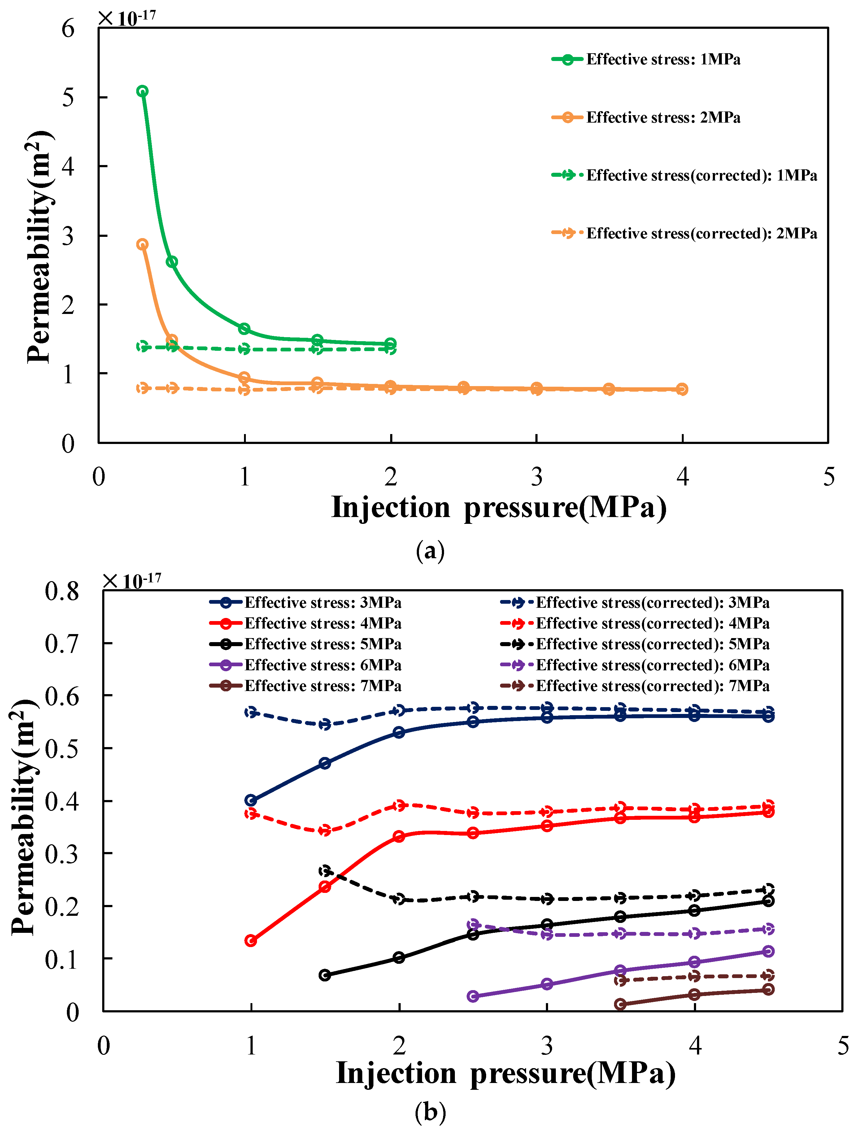
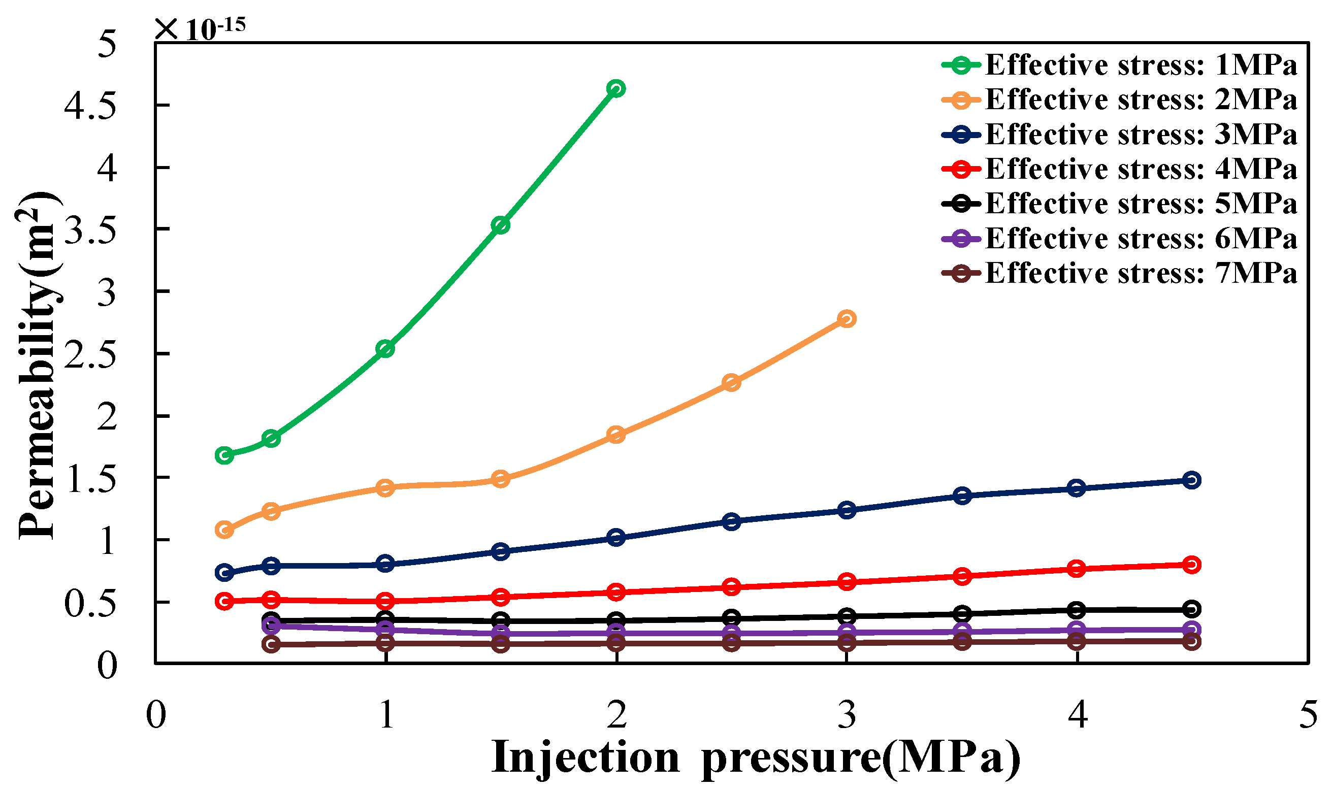
2.2. Characteristics of Permeability Change in the Intact Coal and Damaged Coal
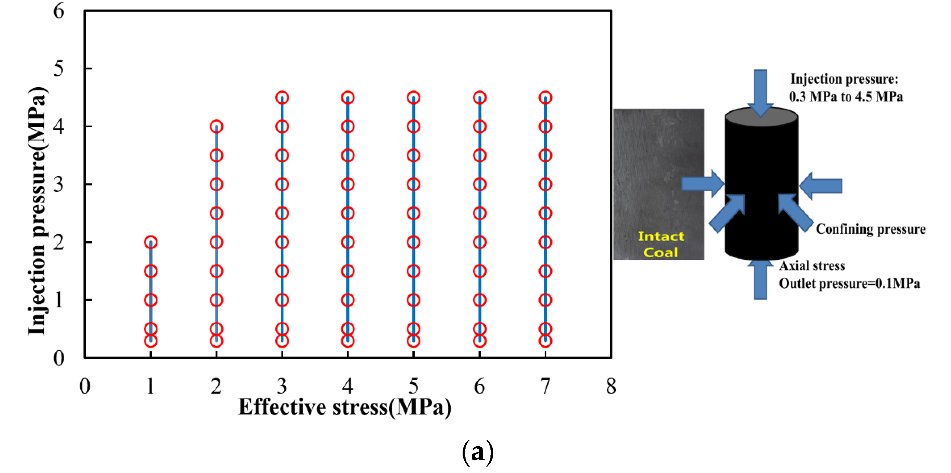
3. Experiment Setup for Tests
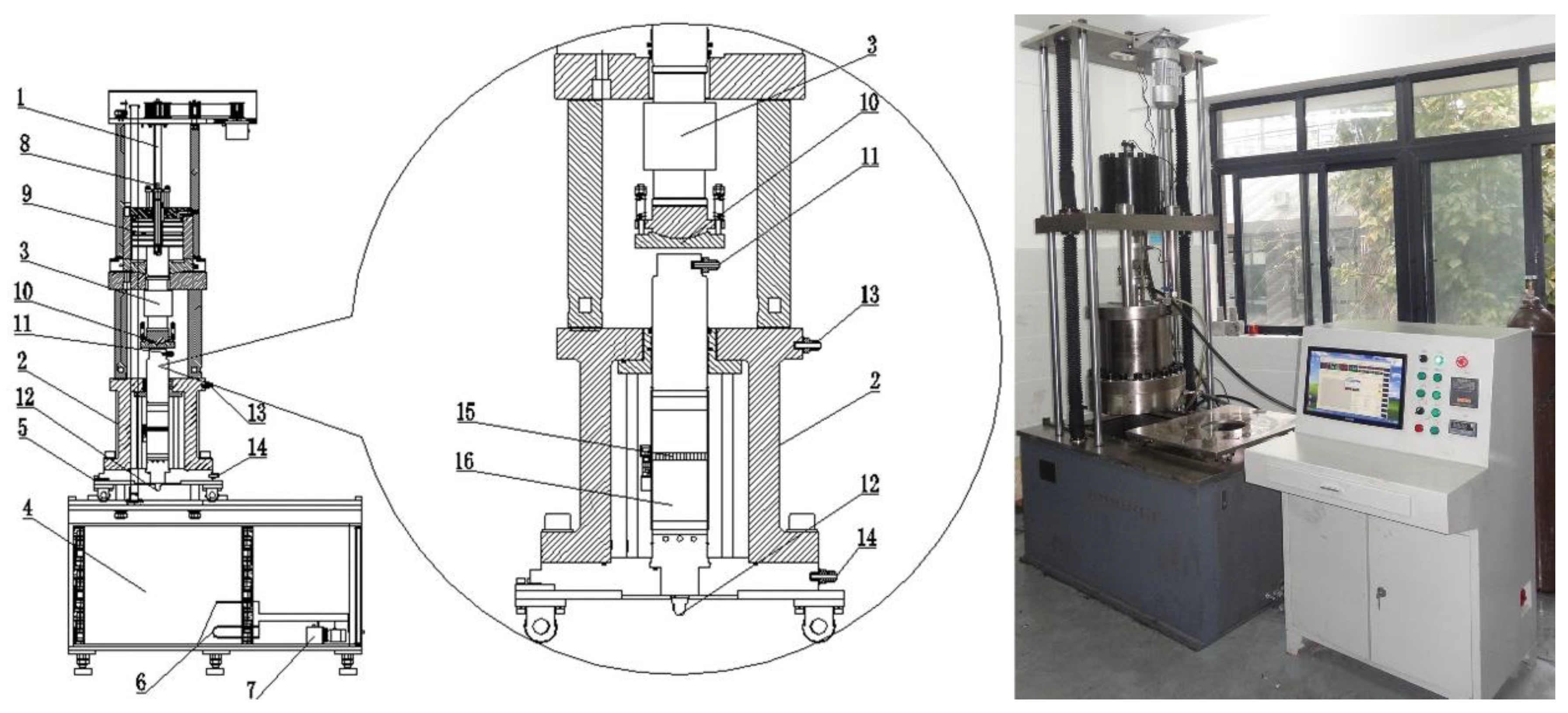
3.1. Experiment Apparatus
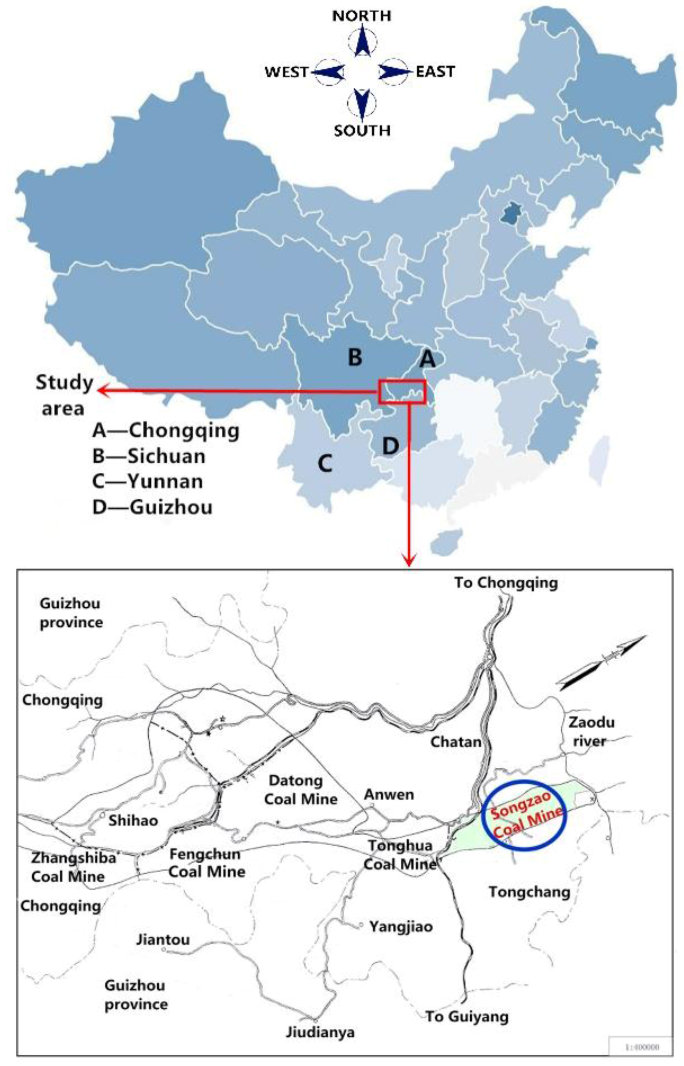
3.2. General Geology of the Sampling Area
3.3. Characterisation of Coal
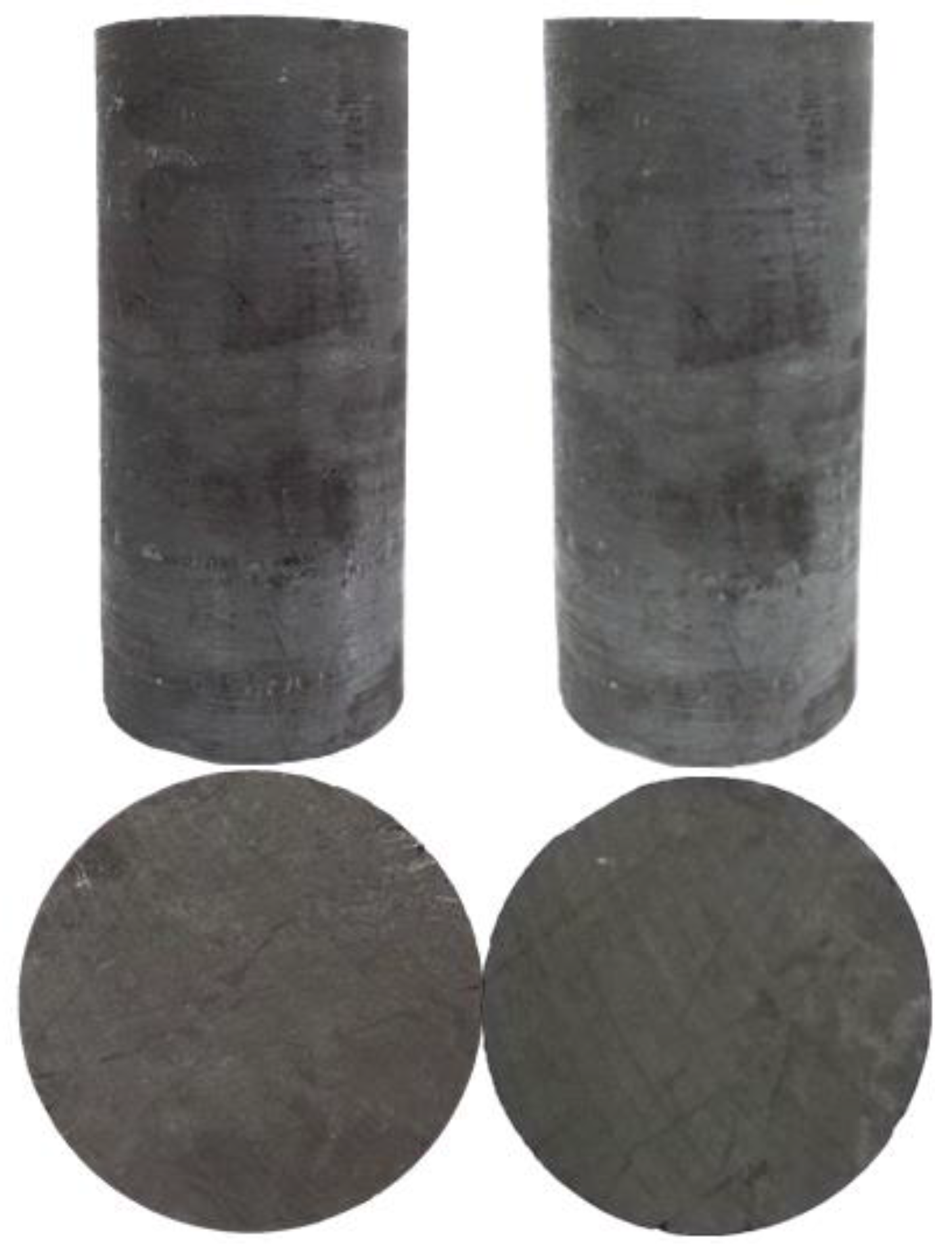
3.4. Specimen Preparation
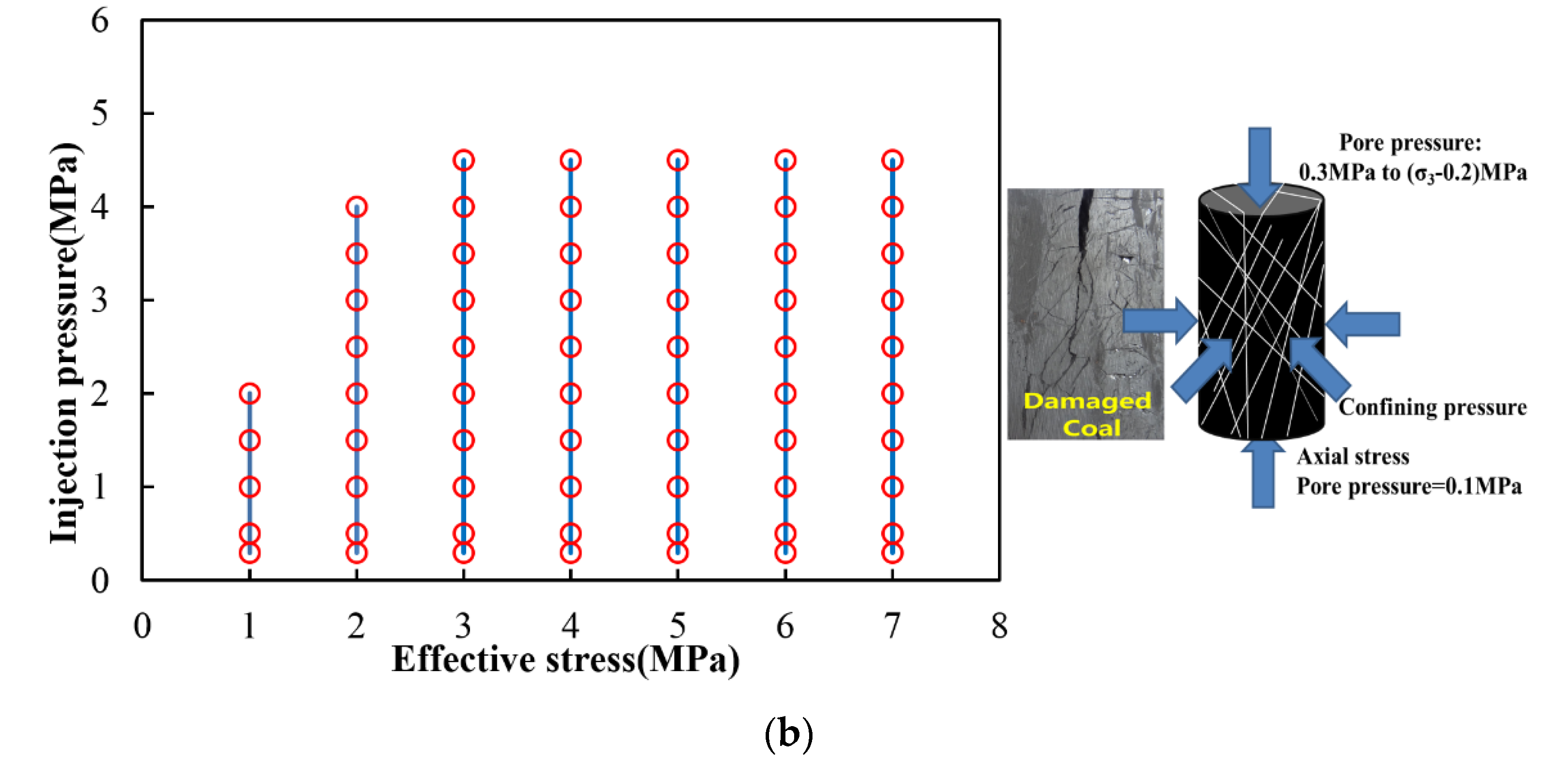
3.5. Experiment Procedure and Data Treatment
4. Conclusions
- (1)
- Both the gas flow rates in the intact coal and damaged coal increased with increasing injection pressure. The gas flow rate in the damaged coal was higher than that in the intact coal by two to three orders of magnitude. The logarithmic relation was found to be available for providing the highest coefficients of determination R2 of fitting curves to describe the relations between the gas flow rates and effective stresses of both the intact coal and damaged coal.
- (2)
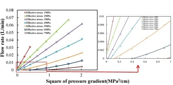
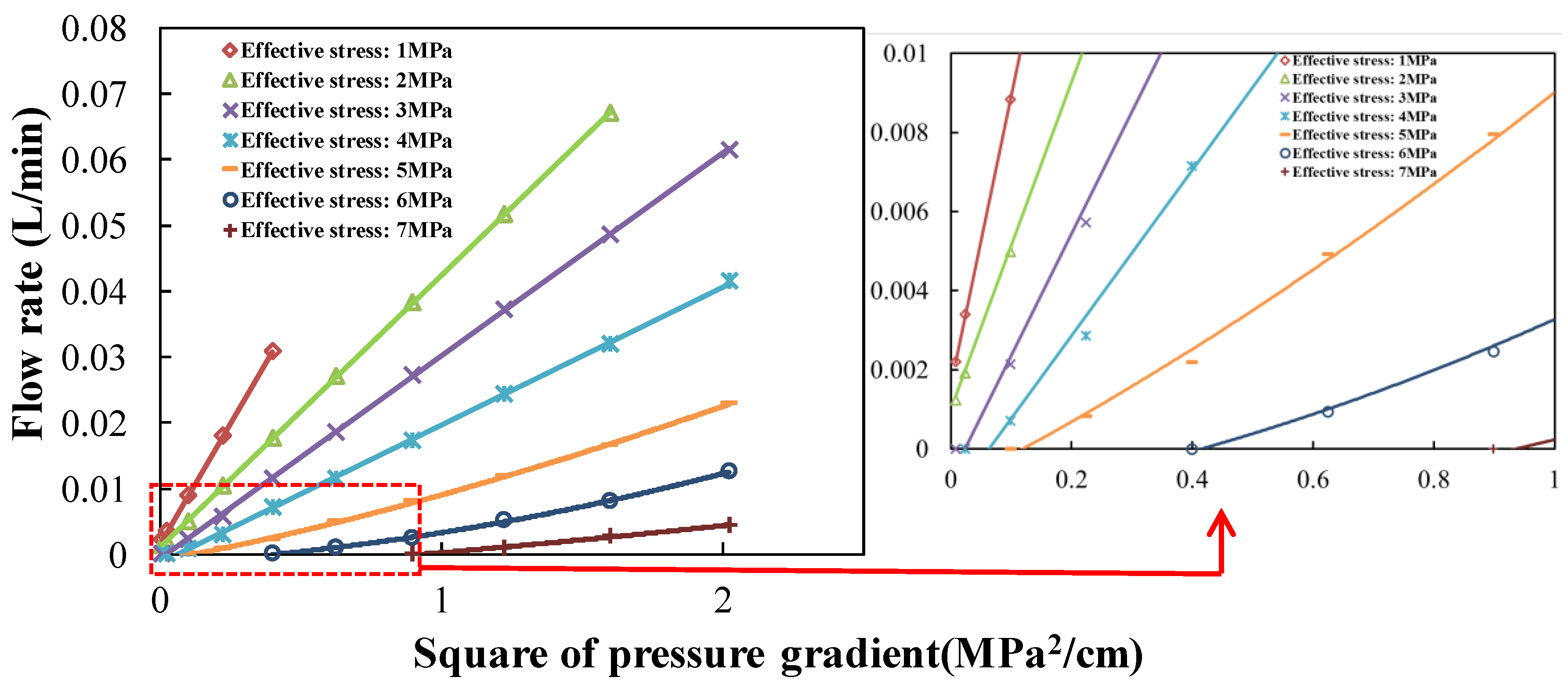
- Pseudo-initial flow rates were observed in the intact coal under low effective stress. Klinkenberg effect may account for this phenomenon. Pseudo-initial flow rate represents the level of slippage force. Based on the pseudo-initial flow rate, the equation to describe relations between gas flow rate and square of pressure gradient in the intact coal under low effective stress has been proposed. As the effective stress increased, the start-up pressure gradients were observed. The start-up pressure gradient increased as the effective stress increased, which indicated that the mobility of gas in the coal was weakened. The start-up pressure gradient represents the level of frictional resistance. Based on the start-up pressure gradient, the equation to describe the relations between gas flow rate and square of pressure gradient in the intact coal has been proposed.
- (3)
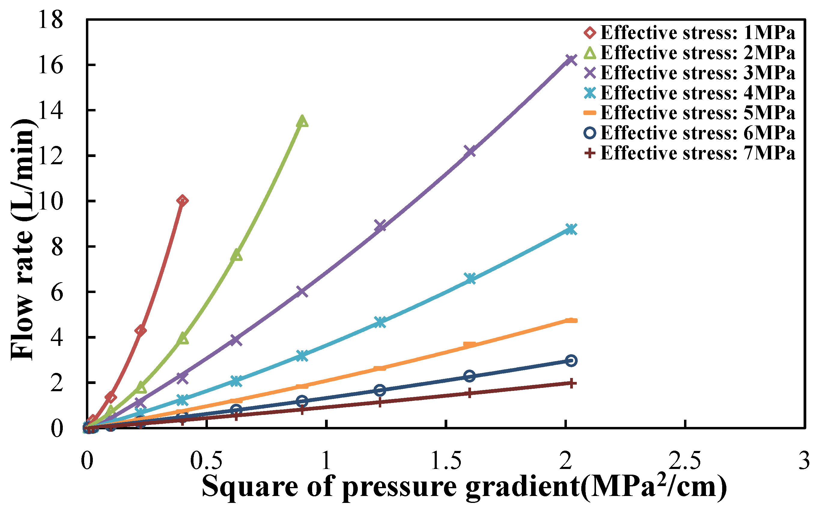
- The gas flow rate in the damaged coal increased nonlinearly as the square of pressure gradient increased under low effective stress. As the effective stress increased, the increase of gas flow rate in the coal turned to be linear. Based on the quadratic function relation and pseudo-initial flow rate, the equation to describe the relations between gas flow rate and square of pressure gradient in the damaged coal under low effective stress has been proposed. In the damaged coal, the original skeleton was damaged and recombined. The increasing injection gas pressure under low effective stress promoted the damage and recombination of coal, which led to the erosion of coal particles. The phenomena would enhance the permeability of coal. Therefore, the coefficient of additional acceleration or resistance α was negative.
- (4)
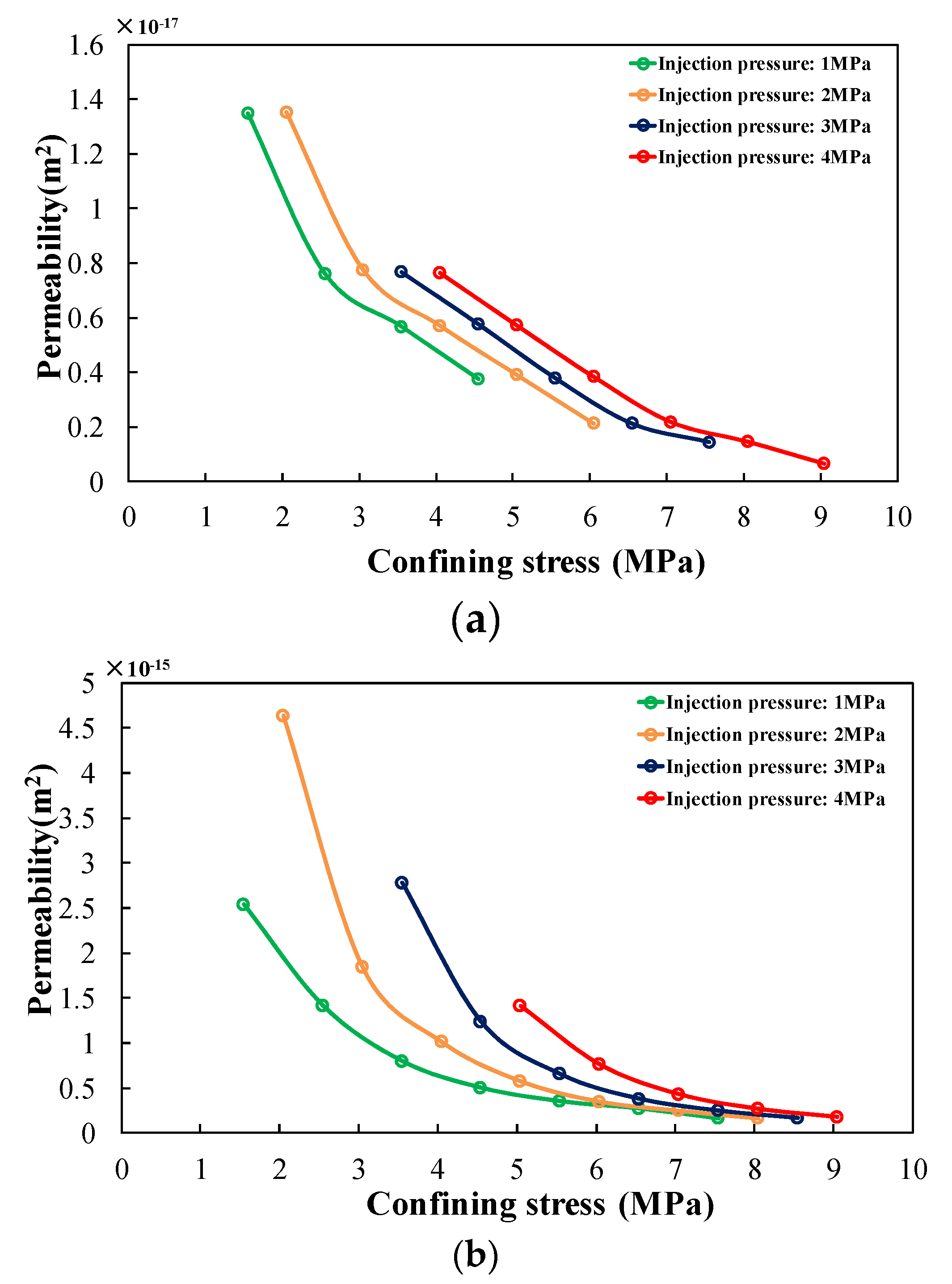
- The apparent permeability in the intact coal calculated by Darcy’s law decreased or increased with increasing injection pressure under the same effective stresses. Whereas, the absolute permeability corrected by the analysis above stayed constant with increasing injection pressure. The deviation of the apparent permeability calculated by Darcy’s law is the result of ignoring the Klinkenberg effect and frictional resistance. The corrected absolute permeability of the intact coal showed advantages in accurately estimating the performance of coal reservoirs.
- (5)
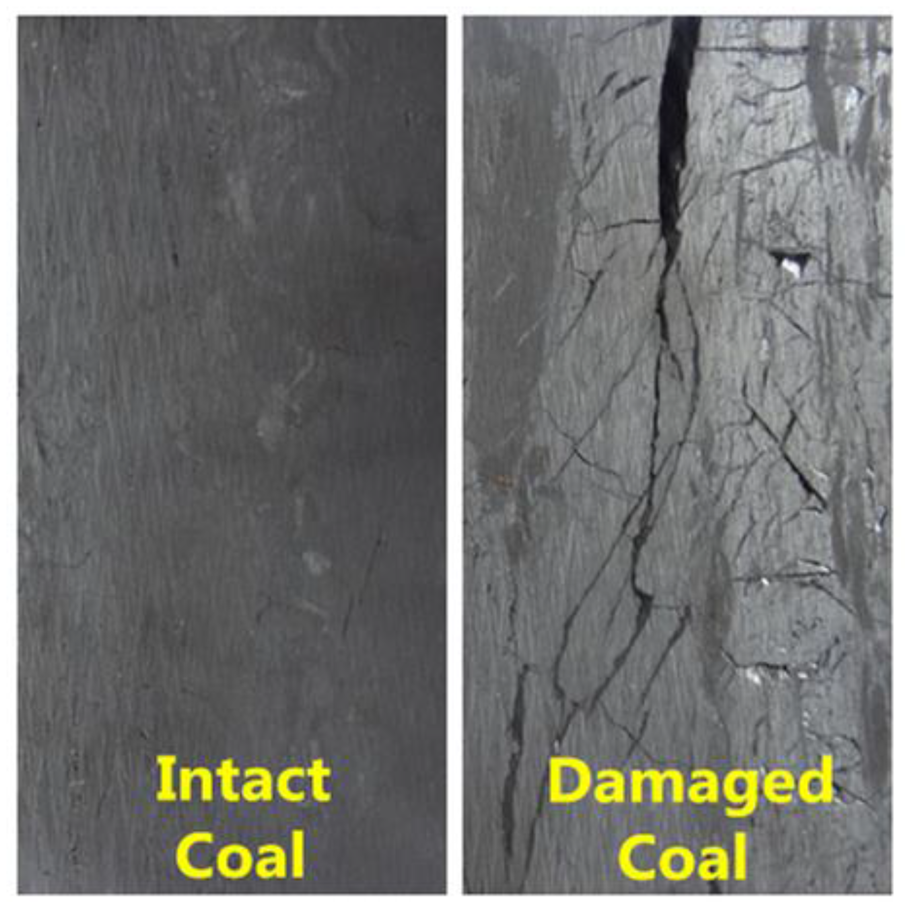
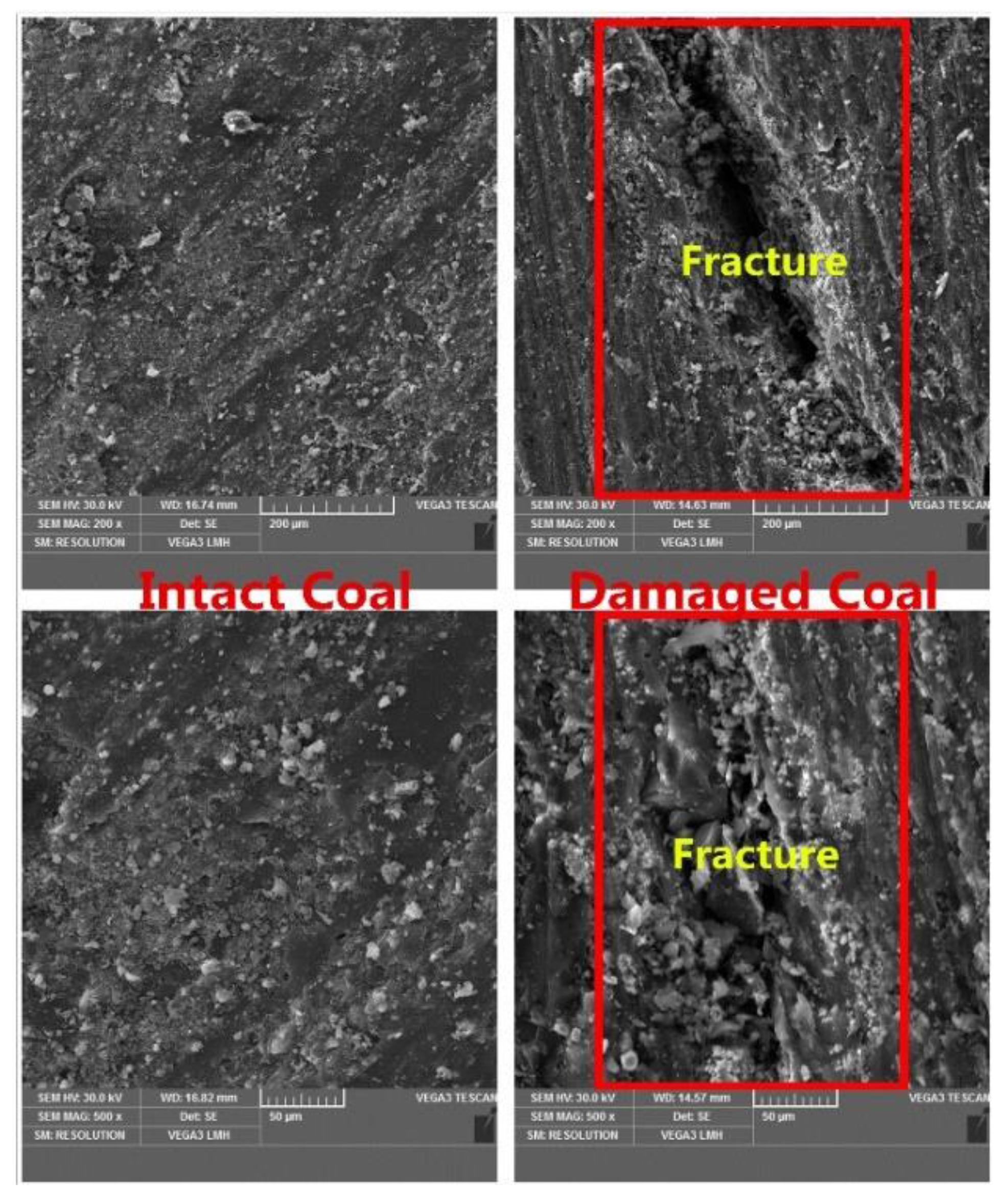
- The permeability in the damaged coal under low effective stress increased with increasing injection pressure. As the effective stress increased, the permeability in coal turned to be constant with increasing injection pressure. Compared with the intact coal, more connecting and obvious fractures are observed in the damaged coal. Thus, the permeability in the damaged coal was higher than that in the intact coal by two to three orders of magnitude.
Supplementary Materials
Acknowledgments
Author Contributions
Conflicts of Interest
References
- Liu, Q.; Cheng, Y.; Yuan, L.; Tong, B.; Kong, S.; Zhang, R. CMM capture engineering challenges and characteristics of in-situ stress distribution in deep level of Huainan coalfield. J. Nat. Gas Sci. Eng. 2015, 20, 328–336. [Google Scholar] [CrossRef]
- Wang, H.; Cheng, Y.; Wang, W.; Xu, R. Research on comprehensive CBM extraction technology and its applications in China’s coal mines. J. Nat. Gas Sci. Eng. 2014, 20, 200–207. [Google Scholar] [CrossRef]
- Yang, W.; Lin, B.; Qu, Y.; Zhao, S.; Zhai, C.; Jia, L.; Zhao, W. Mechanism of strata deformation under protective seam and its application for relieved methane control. Int. J. Coal Geol. 2011, 85, 300–306. [Google Scholar] [CrossRef]
- Liu, T.; Lin, B.; Zou, Q.; Zhu, C.; Guo, C.; Li, J. Investigation on mechanical properties and damage evolution of coal after hydraulic slotting. J. Nat. Gas Sci. Eng. 2015, 24, 489–499. [Google Scholar] [CrossRef]
- Vishal, V.; Ranjith, P.G.; Pradhan, S.P.; Singh, T.N. Permeability of sub-critical carbon dioxide in naturally fractured Indian bituminous coal at a range of down-hole stress conditions. Eng. Geol. 2013, 167, 148–156. [Google Scholar] [CrossRef]
- Vishal, V.; Ranjith, P.G.; Singh, T.N. An experimental investigation on behaviour of coal under fluid saturation, using acoustic emission. J. Nat. Gas Sci. Eng. 2015, 22, 428–436. [Google Scholar] [CrossRef]
- Vishal, V.; Singh, T.N.; Ranjith, P.G. Influence of sorption time in CO2-ECBM process in Indian coals using coupled numerical simulation. Fuel 2015, 139, 51–58. [Google Scholar] [CrossRef]
- Ranathunga, A.S.; Perera, M.S.A.; Ranjith, P.G.; Ju, Y.; Vishal, V.; De Silva, P.N.K. A macro-scale experimental study of sub—and super-critical CO2 flow behaviour in Victorian brown coal. Fuel 2015, 158, 864–873. [Google Scholar] [CrossRef]
- Shen, J.; Qin, Y.; Wang, G.; Fu, X.; Wei, C.; Lei, B. Relative permeabilities of gas and water for different rank coals. Int. J. Coal Geol. 2011, 86, 166–275. [Google Scholar] [CrossRef]
- Pan, Z.J.; Connell, L.D.; Camilleri, M. Laboratory characterisation of coal reservoir permeability for primary and enhanced coalbed methane recovery. Int. J. Coal Geol. 2010, 82, 252–261. [Google Scholar] [CrossRef]
- Li, J.Q.; Liu, D.M.; Yao, Y.B.; Cai, Y.D.; Chen, Y. Evaluation and modeling of gas permeability changes in anthracite coals. Fuel 2013, 111, 606–612. [Google Scholar] [CrossRef]
- Chareonsuppanimit, P.; Mohammad, S.A.; Robinson, R.L., Jr.; Gasem, K.A.M. Modeling gas-adsorption-induced swelling and permeability changes in coals. Int. J. Coal Geol. 2014, 121, 98–109. [Google Scholar] [CrossRef]
- Vishal, V.; Singh, T.N. A laboratory investigation of permeability of coal to supercritical CO2. Geotech. Geol. Eng. 2015, 33, 1009–1016. [Google Scholar] [CrossRef]
- Zhang, J.; Standifird, W.B.; Roegiers, J.C.; Zhang, Y. Stress-dependent fluid flow and permeability in fractured media: From lab experiments to engineering applications. Rock Mech. Rock Eng. 2007, 40, 3–21. [Google Scholar] [CrossRef]
- Zheng, J.; Zheng, L.; Liu, H.; Ju, Y. Relationships between permeability, porosity and effective stress for low-permeability sedimentary rock. Int. J. Rock Mech. Min. Sci. 2015, 78, 304–318. [Google Scholar] [CrossRef]
- Cai, Y.D.; Liu, D.M.; Jonathan, P.M.; Pan, Z.J.; Elsworth, D.; Yao, Y.B.; Li, J.Q.; Guo, X.Q. Permeability evolution in fractured coal-combining triaxial confinement with X-ray computed tomography, acoustic emission and ultrasonic techniques. Int. J. Coal Geol. 2014, 122, 91–104. [Google Scholar] [CrossRef]
- Xie, H.; Xie, J.; Gao, M.; Zhang, R.; Zhou, H.; Gao, F.; Zhang, Z. Theoretical and experimental validation of mining-enhanced permeability for simultaneous exploitation of coal and gas. Environ. Earth Sci. 2015, 73, 5951–5962. [Google Scholar] [CrossRef]
- Yin, G.; Li, M.; Wang, J.G.; Xu, J.; Li, W. Mechanical behavior and permeability evolution of gas infiltrated coals during protective layer mining. Int. J. Rock Mech. Min. Sci. 2015, 80, 292–301. [Google Scholar] [CrossRef]
- Wang, S.G.; Elsworth, D.; Liu, J.S. Permeability evolution during progressive deformation of intact coal and implications for instability in underground coal seams. Int. J. Rock Mech. Min. Sci. 2013, 58, 34–45. [Google Scholar] [CrossRef]
- Xie, J.; Gao, M.; Yu, B.; Zhang, R.; Jin, W. Coal permeability model on the effect of gas extraction within effective influence zone. Geomech. Geophys. Geo-Energy Geo-Resour. 2015, 1, 15–27. [Google Scholar] [CrossRef]
- Klinkenberg, L.J. The permeability of porous media to liquids and gases. Drill. Prod. Pract. 1941, 200–213. [Google Scholar]
- Swartzendruber, D. Non-Darcy flow behavior in liquid-saturated porous media. J. Geophys. Res. 1962, 67, 5205–5213. [Google Scholar] [CrossRef]
- Miller, R.J.; Low, P.F. Threshold gradient of water in clay systems. Soil Sci. Soc. Am. J. 1963, 27, 605–609. [Google Scholar] [CrossRef]
- Forchheimer, P. Wasserbewegun Durch Boden. Z. Ver. Deutsch. Ing. 1901, 45, 1782–1788. [Google Scholar]
- Hassanizadeh, S.M.; Gray, W.G. High velocity flow in porous media. Trans. Porous Media 1987, 2, 521–531. [Google Scholar] [CrossRef]
- Nashawi, I.S. Constant-pressure well test analysis of finite-conductivity hydraulically fractured gas wells influenced by non-Darcy flow effects. J. Pet. Sci. Eng. 2006, 53, 225–238. [Google Scholar] [CrossRef]
- Zeng, F.; Zhao, G. Gas well production analysis with non-Darcy flow and real-gas PVT behavior. J. Pet. Sci. Eng. 2007, 59, 169–182. [Google Scholar] [CrossRef]
- Mahdiyar, H.; Jamiolahmady, M.; Sohrabi, M. Improved Darcy and non-Darcy flow formulations around hydraulically fractured wells. J. Pet. Sci. Eng. 2011, 78, 149–159. [Google Scholar] [CrossRef]
- Jasinge, D.; Ranjith, P.G.; Choi, S.K. Effects of effective stress changes on permeability of Latrobe Valley brown coal. Fuel 2011, 90, 1292–1300. [Google Scholar] [CrossRef]
- Miao, X.; Chen, Z.; Mao, X. The bifurcation of non-Darcy flow in post-failure rock. Acta Mech. Sin. 2003, 35, 660–667. [Google Scholar]
- Vishal, V.; Ranjith, P.G.; Singh, T.N. CO2 permeability of Indian bituminous coals: Implications for carbon sequestration. Int. J. Coal Geol. 2013, 105, 36–47. [Google Scholar] [CrossRef]
- Harpalani, S.; Chen, G. Influence of gas production induced volumetric strain on permeability of coal. Geotech. Geol. Eng. 1997, 15, 303–325. [Google Scholar] [CrossRef]
- Ranjith, P.G.; Perera, M.S.A. A new triaxial apparatus to study the mechanical and fluid flow aspects of carbon dioxide sequestration in geological formations. Fuel 2011, 90, 2751–2759. [Google Scholar] [CrossRef]
- Hildenbrand, A.; Schlömer, S.; Krooss, B.M. Gas breakthrough experiments on fine-grained sedimentary rocks. Geofluids 2002, 2, 3–23. [Google Scholar] [CrossRef]


| Injection Pressure (Intact Coal) | a | b | R2 | Injection Pressure (Damaged Coal) | a | b | R2 |
|---|---|---|---|---|---|---|---|
| 1 MPa | −0.006 | 0.009 | 0.993 | 1 MPa | −0.664 | 1.264 | 0.966 |
| 2 MPa | −0.017 | 0.030 | 0.997 | 2 MPa | −4.806 | 8.5659 | 0.904 |
| 3 MPa | −0.032 | 0.061 | 0.993 | 3 MPa | −9.871 | 18.453 | 0.900 |
| 4 MPa | −0.054 | 0.105 | 0.994 | 4 MPa | −12.580 | 24.977 | 0.944 |
| Layer Number | Lithology | Thickness (m) |
|---|---|---|
| 1 | Alluvium | 460 |
| 2 | Sandstone | 5.45 |
| 3 | Sandy mudstone | 2.65 |
| 4 | Coal seam | 1.83 |
| 5 | Sandy mudstone | 7.43 |
| 6 | Limestone | 1.25 |
| 7 | Sandstone | 3.96 |
| 8 | Limestone | 1.01 |
| 9 | Sandy mudstone | 3.18 |
| 10 | Argillaceous limestone | 4.90 |
| 11 | Coal seam | 0.75 |
| 12 | Sandy mudstone | 3.72 |
| 13 | Coal seam | 0.24 |
| 14 | Sandy mudstone | 3.41 |
| 15 | Siliceous limestone | 1.56 |
| 16 | Calcareous mudstone | 1.19 |
| BET Surface Area (m2/g) | Langmuir Surface Area (m2/g) | Total Pore Volume (cm3/g) | Average Pore Width (Å) | Mad (%) | Aad (%) | Vad (%) | Fcad (%) |
|---|---|---|---|---|---|---|---|
| 0.2997 | 0.4744 | 0.0014 | 189.5302 | 1.17 | 13.16 | 21.03 | 64.64 |
| UCS (MPa) | Density (kg/m3) | Young’s Modulus (GPa) | Poisson’s ratio | ||||
| 14.72 | 1460 | 4.77 | 0.21 | ||||
© 2016 by the authors; licensee MDPI, Basel, Switzerland. This article is an open access article distributed under the terms and conditions of the Creative Commons Attribution (CC-BY) license (http://creativecommons.org/licenses/by/4.0/).
Share and Cite
Li, M.; Cao, J.; Li, W. Stress and Damage Induced Gas Flow Pattern and Permeability Variation of Coal from Songzao Coalfield in Southwest China. Energies 2016, 9, 351. https://doi.org/10.3390/en9050351
Li M, Cao J, Li W. Stress and Damage Induced Gas Flow Pattern and Permeability Variation of Coal from Songzao Coalfield in Southwest China. Energies. 2016; 9(5):351. https://doi.org/10.3390/en9050351
Chicago/Turabian StyleLi, Minghui, Jie Cao, and Wenpu Li. 2016. "Stress and Damage Induced Gas Flow Pattern and Permeability Variation of Coal from Songzao Coalfield in Southwest China" Energies 9, no. 5: 351. https://doi.org/10.3390/en9050351