
Effect of Borehole Material on Analytical Solutions of the Heat Transfer Model of Ground Heat Exchangers Considering Groundwater Flow


Abstract
:
1. Introduction
2. Analytical Model for Heat Transfer
2.1. Analytical Model for Pure Conduction
- (1)
- Both the inside and outside of the heat source circumference are considered as one homogeneous medium, and the thermo-physical properties are constant with temperature changes.
- (2)
- The homogeneous medium has a uniform initial temperature, , and the heating rate per unit length of heat source, (W/m), is constant from the initial state, .
- (3)
- The heat source is buried in the homogeneous medium in accordance with z-axis. The thickness, mass and heat capacity of the heat source are neglected.
- (4)
- The temperature boundary of the medium (i.e., ground surface) is maintained as constant initial temperature, .
2.2. Analytical Model for Heat Transfer with Groundwater Flow
- (1)
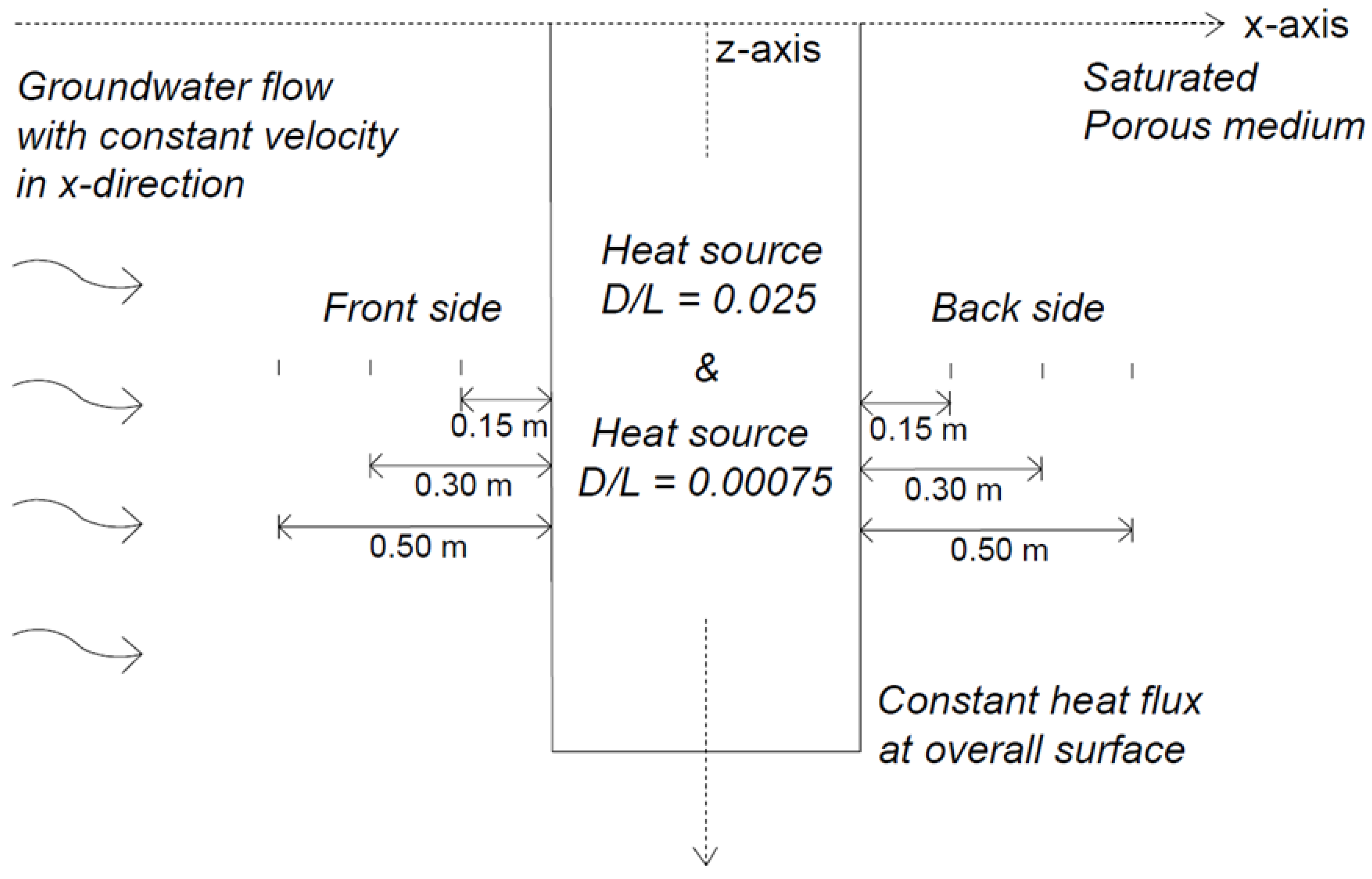
- The groundwater seeps through at a constant velocity, u, exclusively in the x-direction in the medium
- (2)
- The inner part of the heat source is the same as the surrounding medium, which means the velocity of groundwater flow through the inner part of the borehole with same velocity of the surrounding medium.
3. Numerical Analysis of Combined Heat Transfer Mechanism
3.1. Overview of Numerical Model
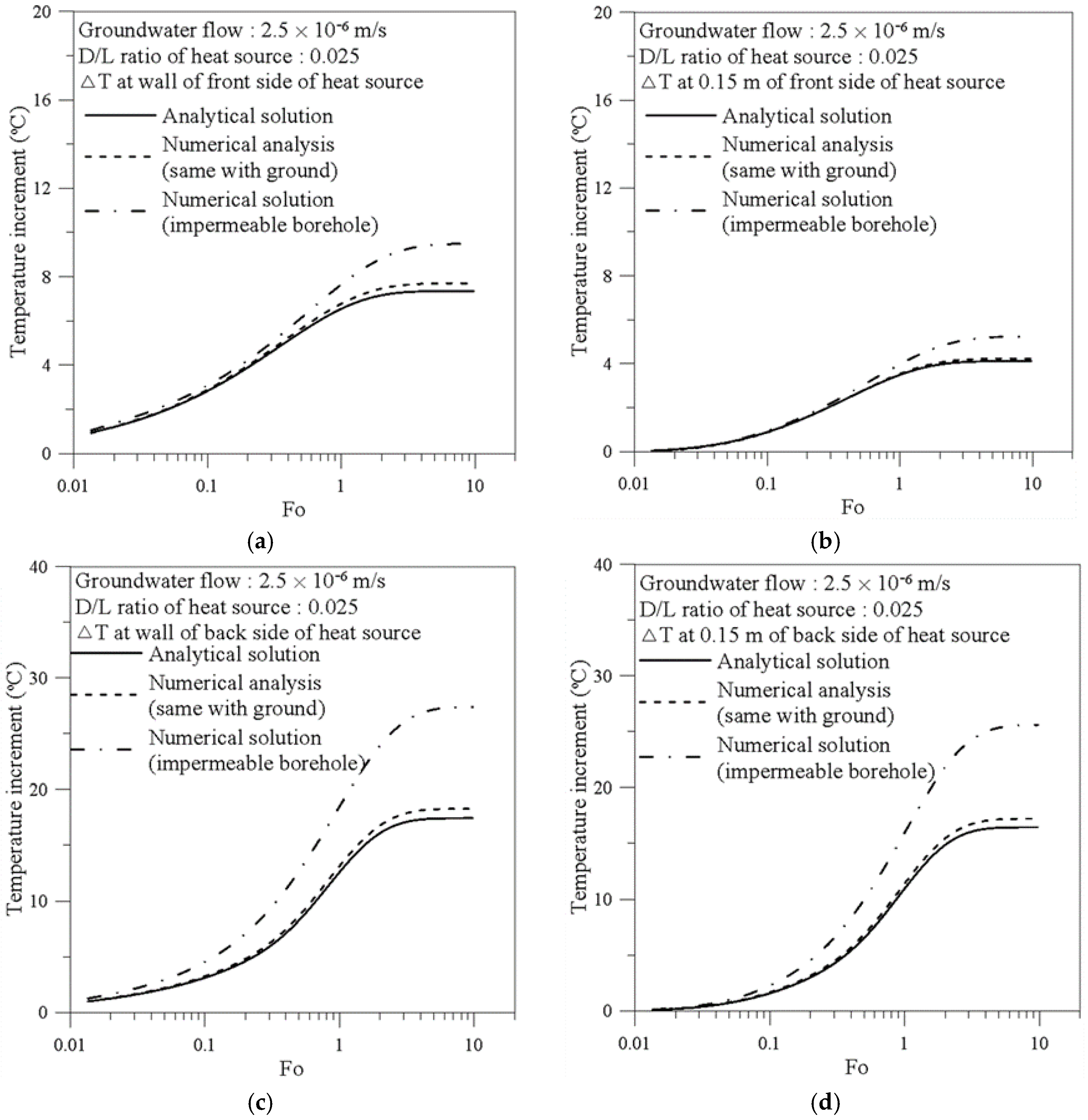
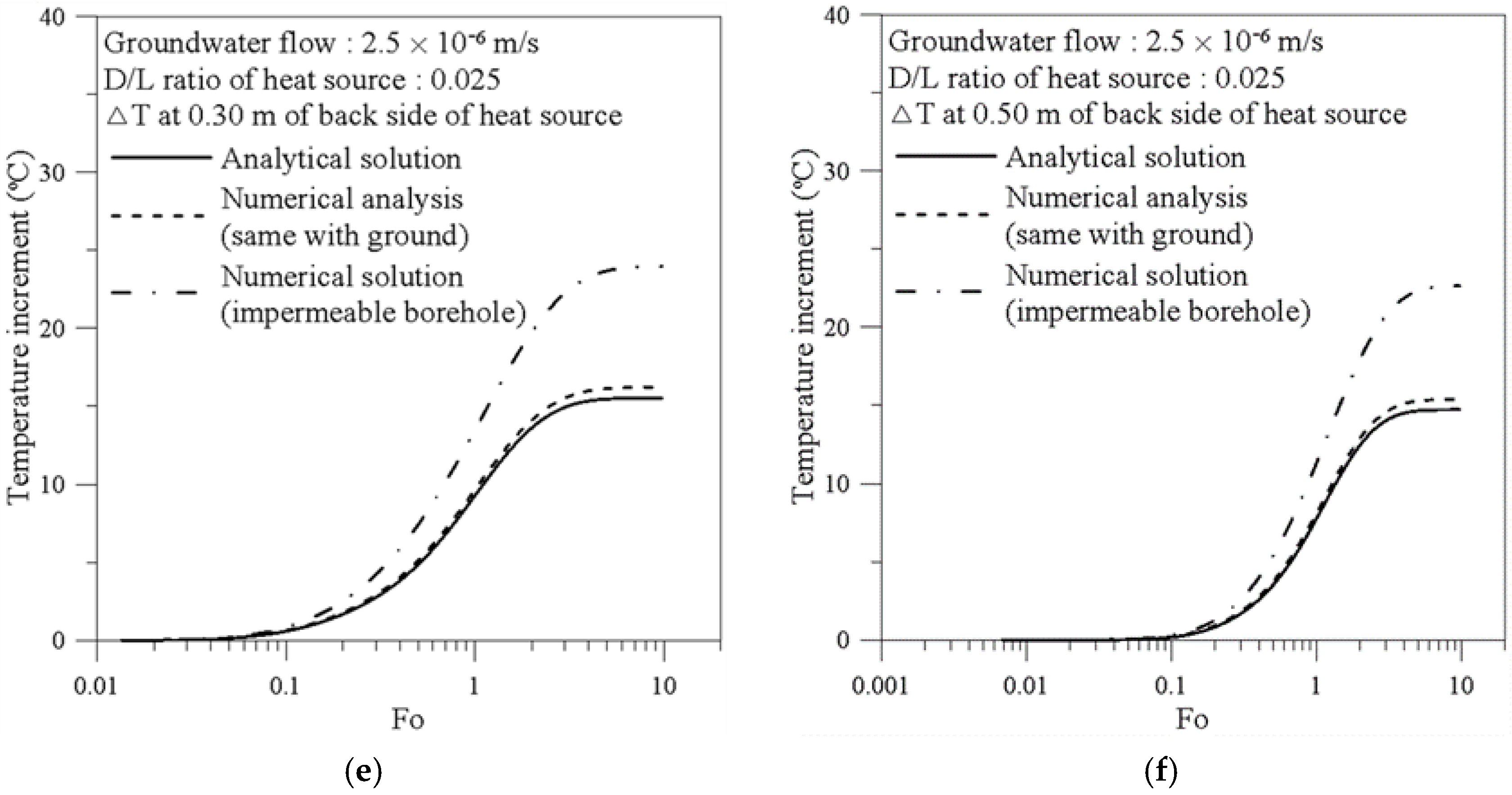
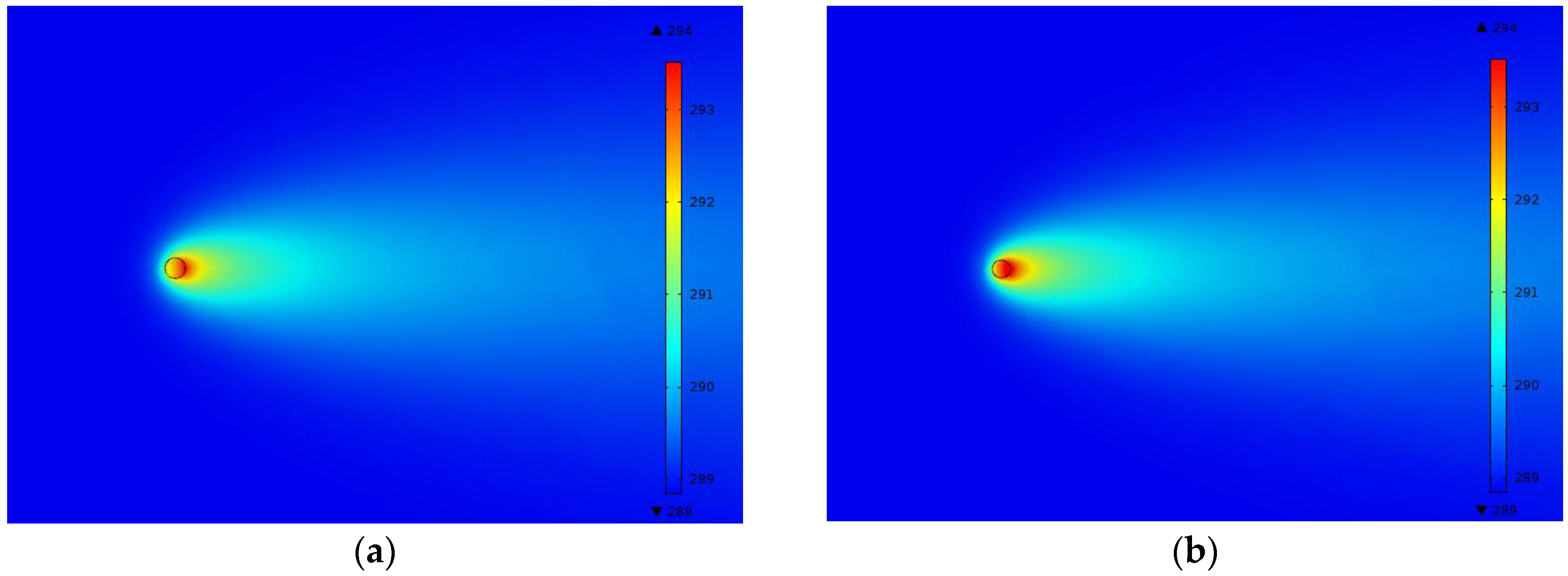
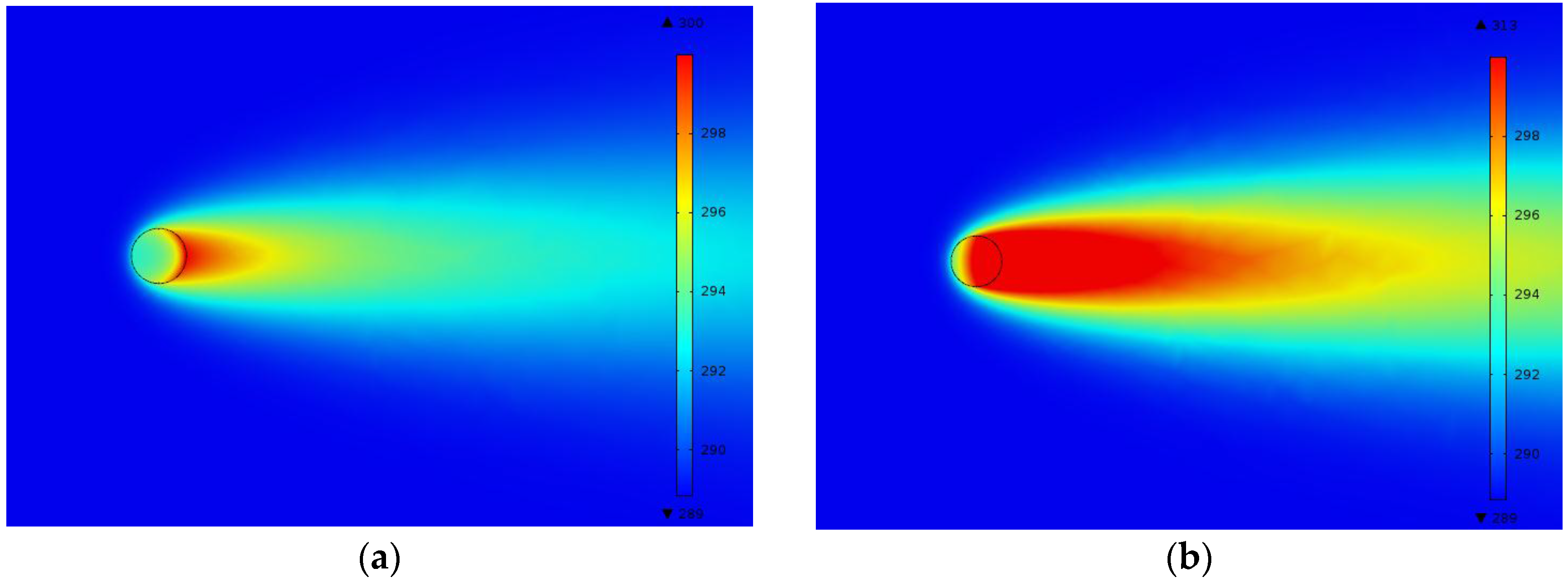
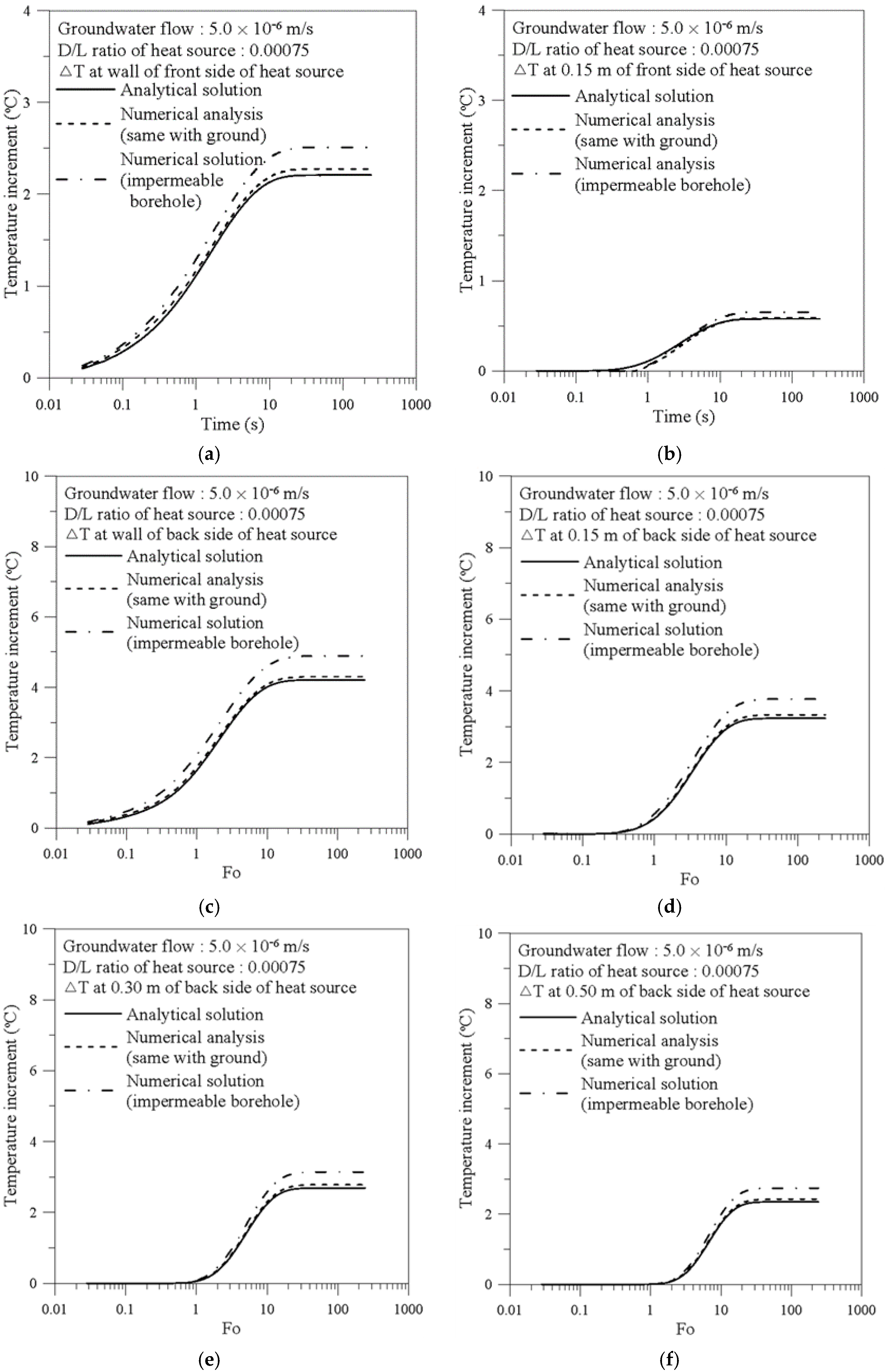
3.2. Effect of Impermeable Borehole on Ground Thermal Behavior
- (1)
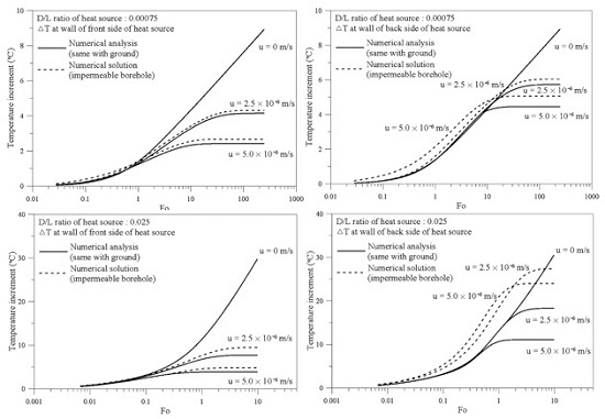
- The combined analytical solution largely deviates from the actual underground thermal behavior around buried GHEXs with a large diameter and relatively small length (i.e., large value of D/L ratio).
- (2)
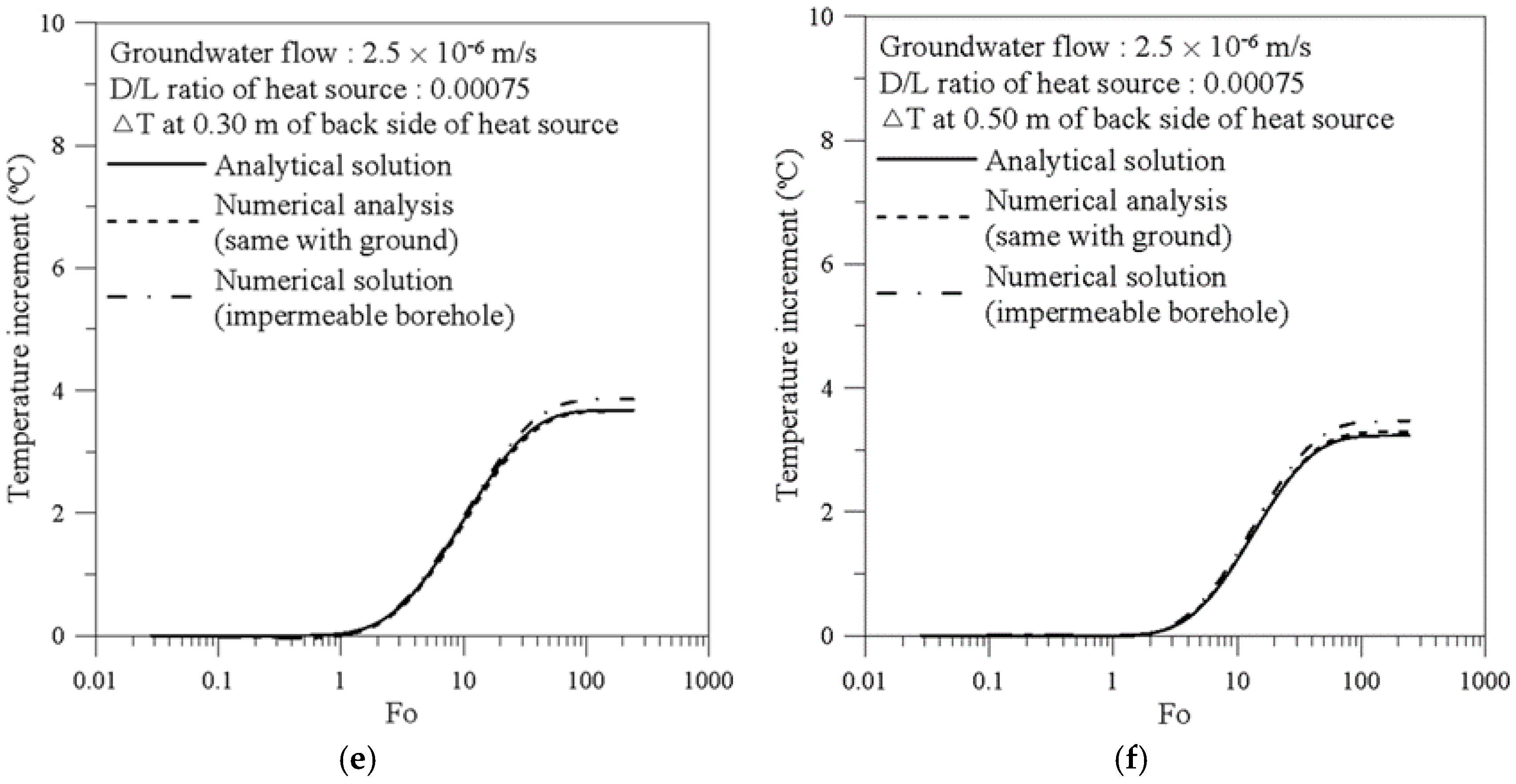
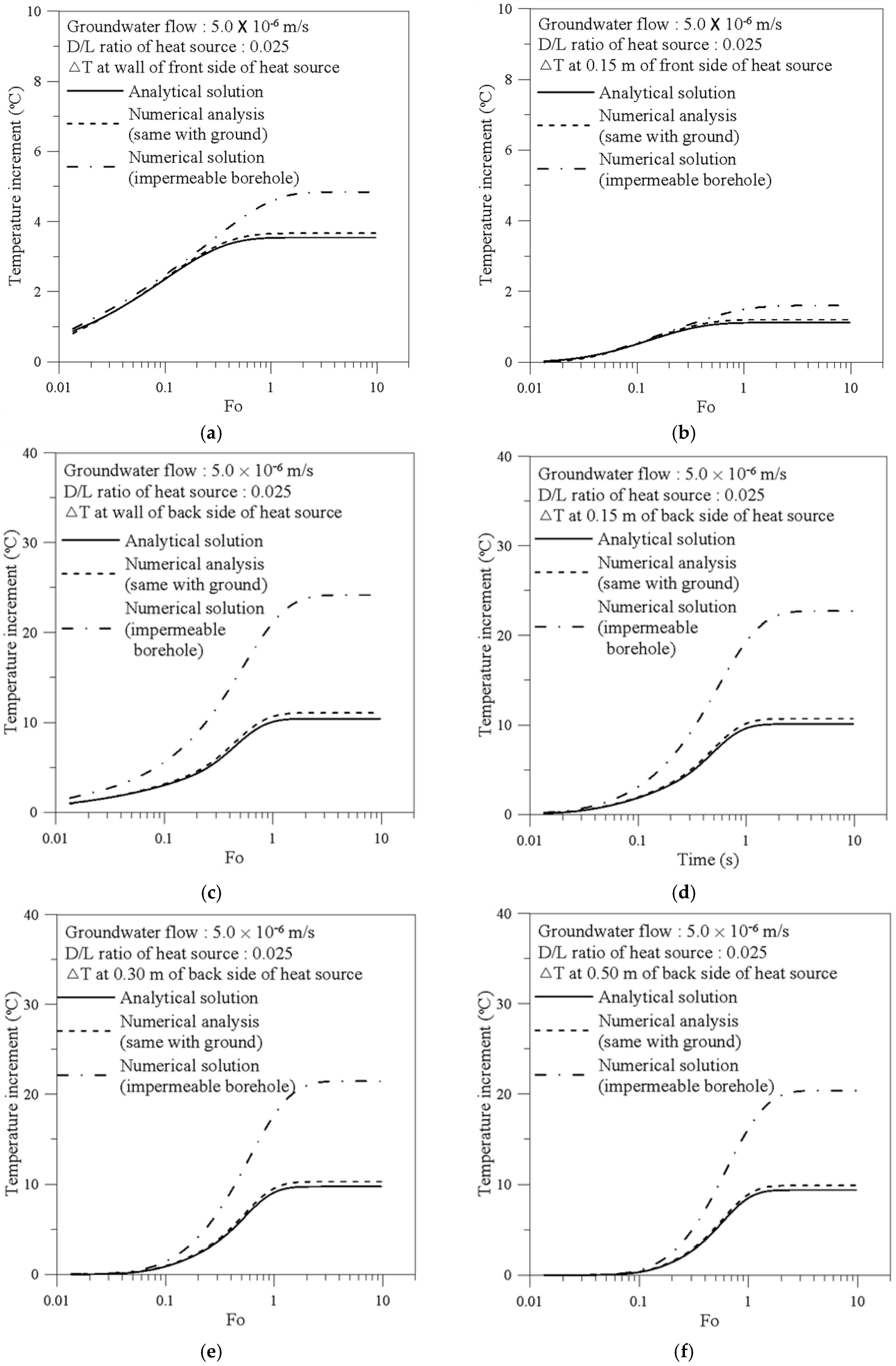
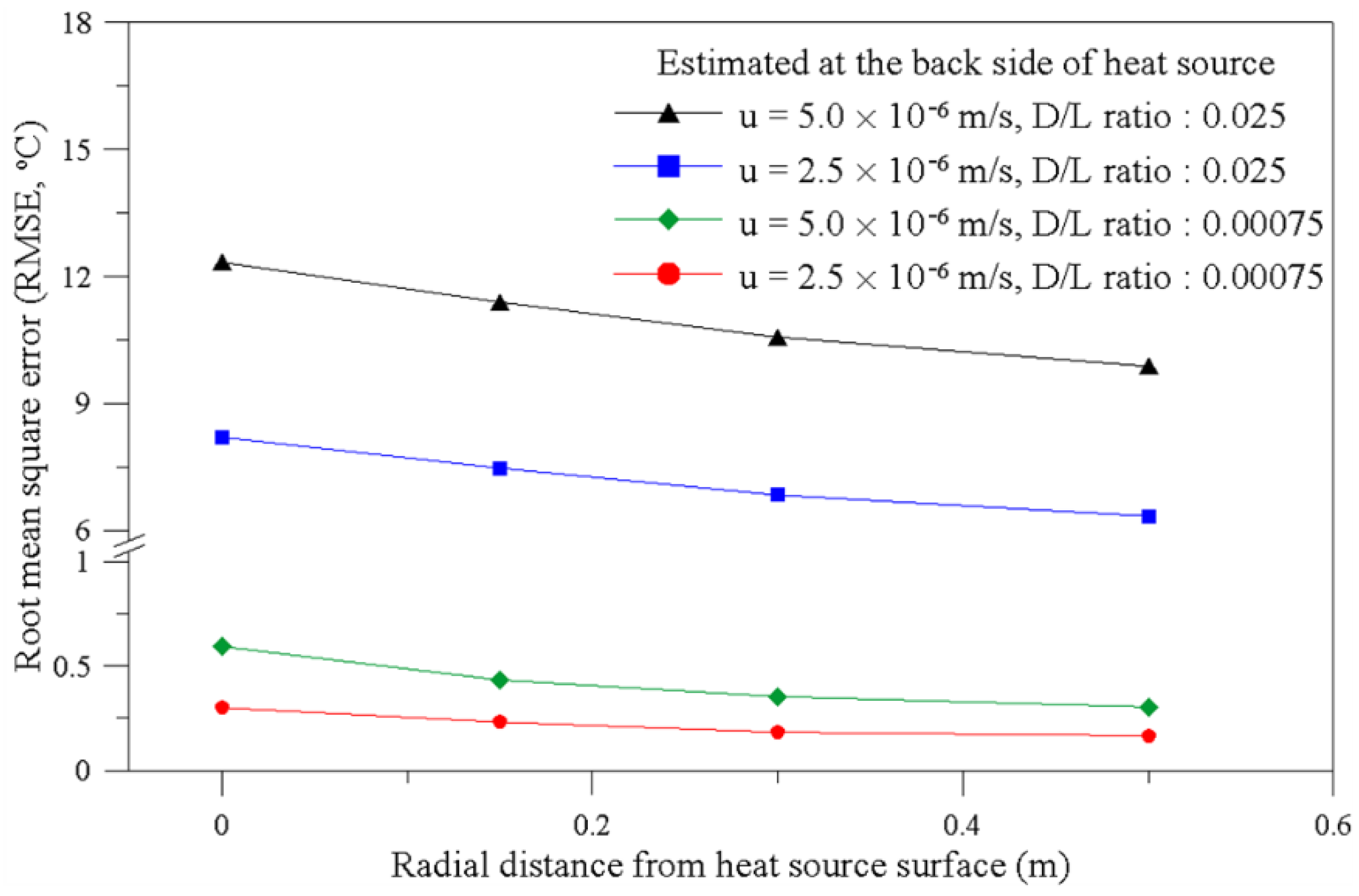
- The accuracy of the combined analytical solution is significantly reduced at the back side of the heat source, which is more affected by the impermeable borehole than the front side of the heat source.
- (3)
- As the groundwater velocity increases, the error caused by the critical assumption in the analytical solution increases.
4. Conclusions
- (1)
- A series of numerical analyses was performed with different borehole materials (i.e., same material as that of the surrounding ground formation and impermeable material), groundwater velocities (i.e., 0 m/s, 2.5 × 10⁻⁶ m/s, and 5.0 × 10⁻⁶ m/s) and D/L ratios of heat source (i.e., 0.00075 and 0.025). The developed numerical model successfully reflects the effect of ground water and permeability of borehole.
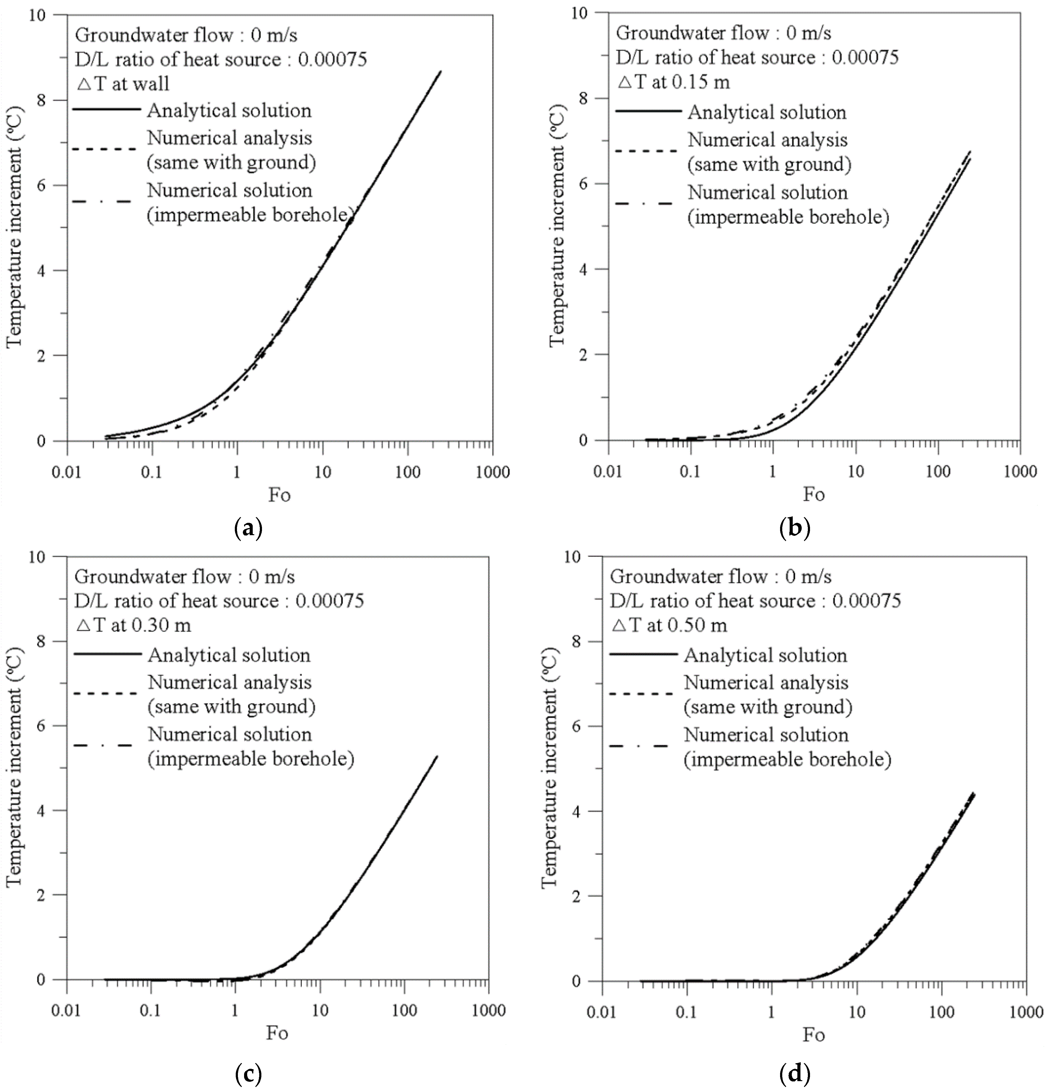
- (2)
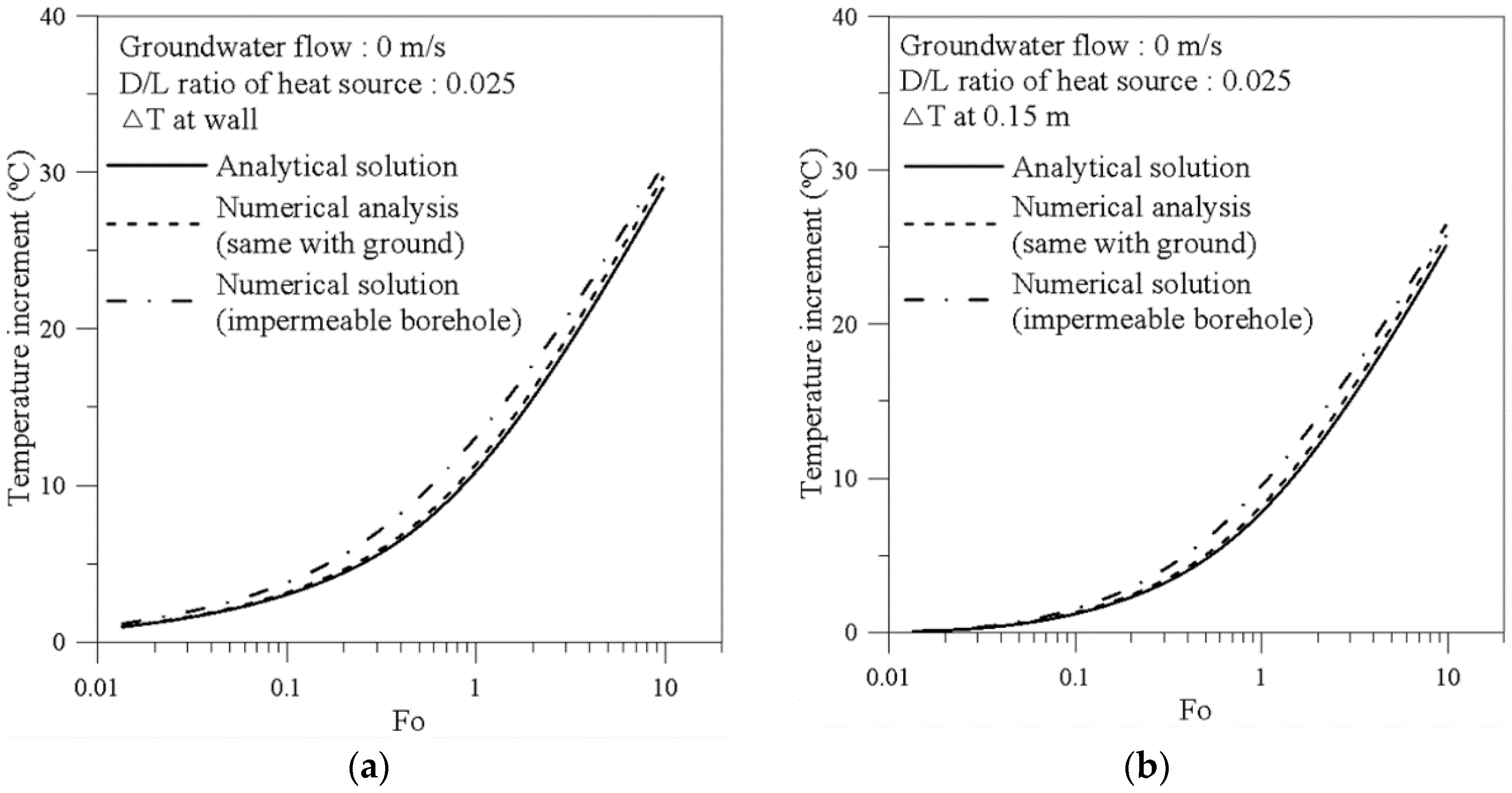
- In the case of no groundwater flow, the developed numerical model can simulate pure conduction showing a good agreement with the analytical solution in both D/L ratios when the inner part of the heat source is assumed to be the same as the surrounding ground formation. However, when the inner part of the heat source is modeled as impermeable material, the analytical solution slightly deviates from the numerical analysis result, especially for the D/L ratio of 0.025, because the effect of different thermo-physical properties is enhanced with an increase in borehole volume.
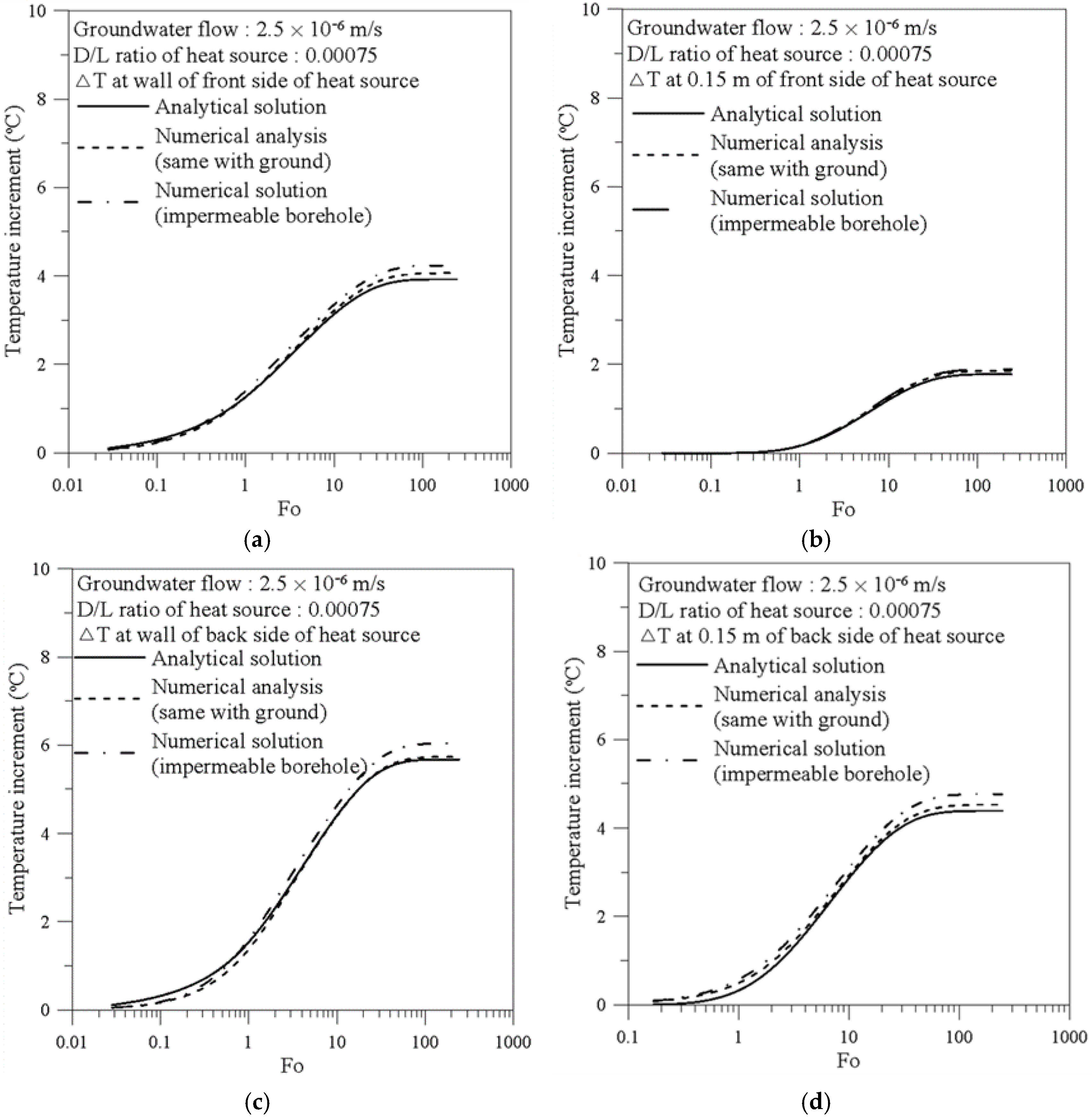
- (3)
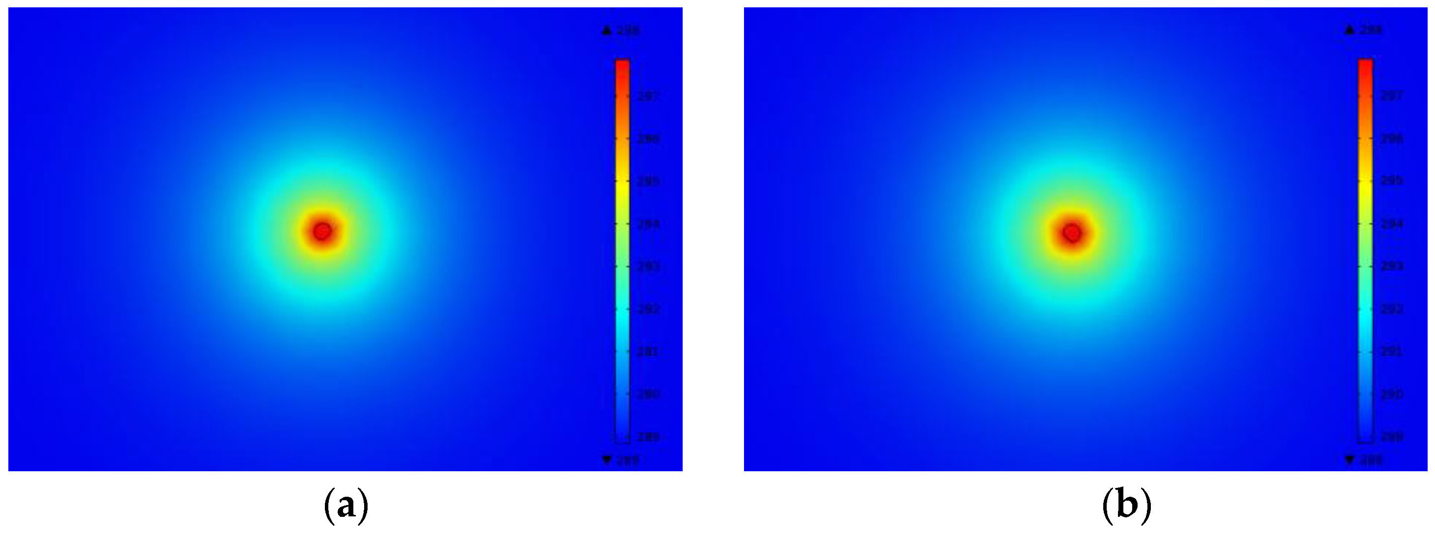
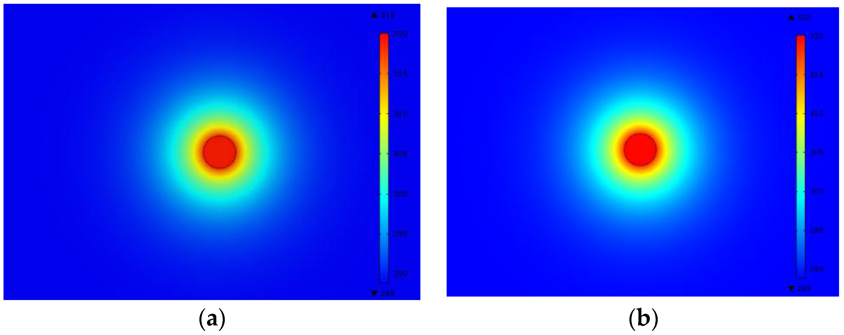
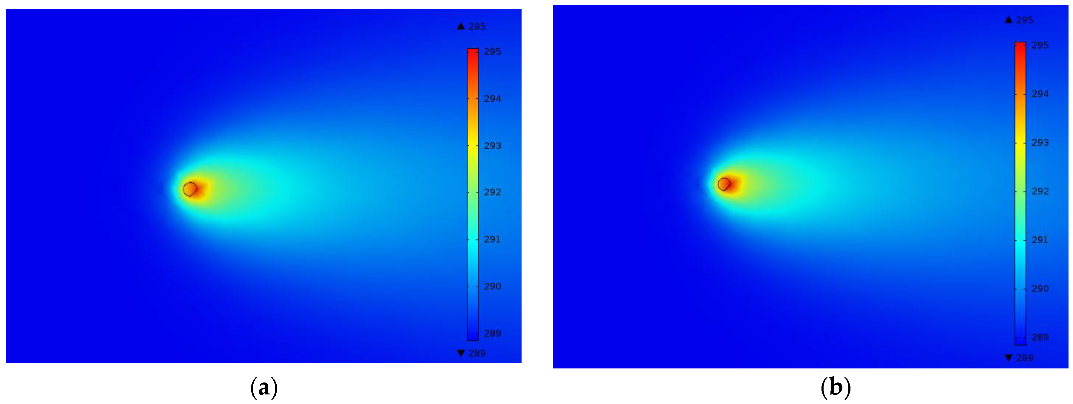
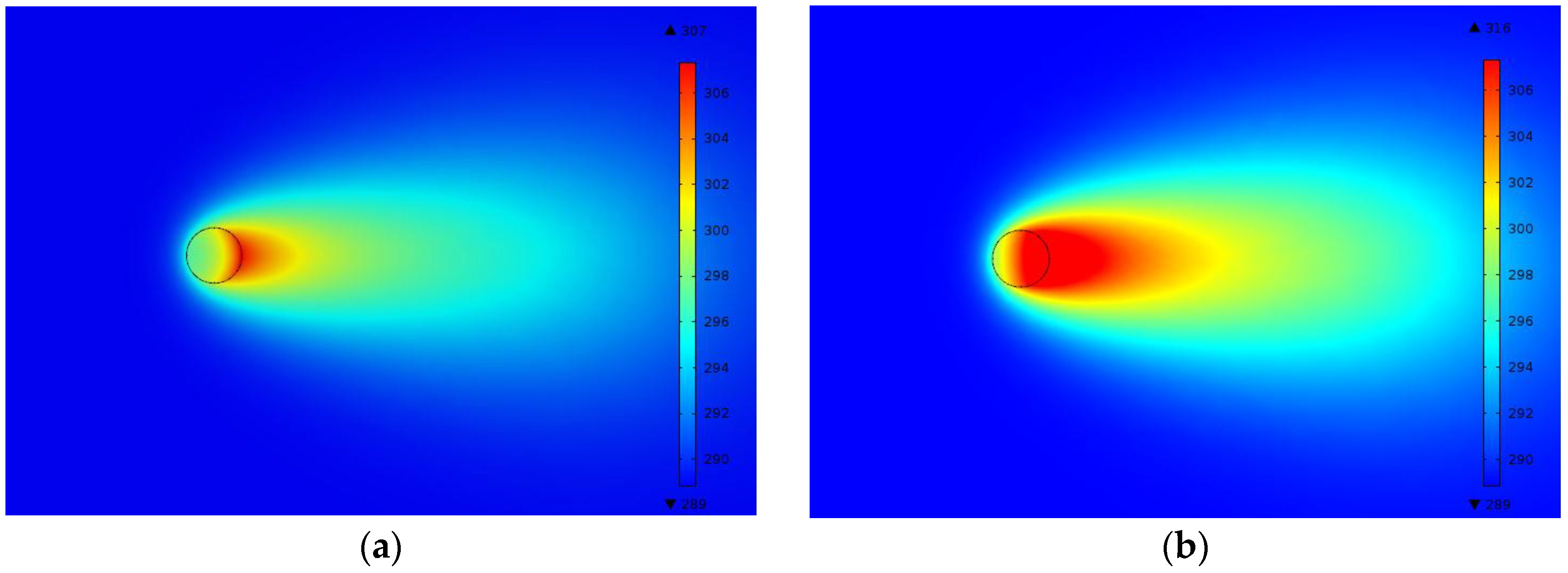
- The groundwater flow significantly reduces the temperature at the front side of the heat source by eliminating the heat. On the other hand, the groundwater flow causes a larger temperature increment at the back side of the heat source than at the front side by accumulating the heat taken up from the front side. However, if the borehole is impermeable, the thermal convection due to groundwater flow is significantly reduced compared to the permeable borehole, which leads to a rapid increase in temperature at the back side of the heat source.
- (4)
- The accuracy of the combined solid cylindrical heat source model is reduced at the back side of the heat source, which is more affected by the existence of impermeable borehole than the front side of the heat source. Moreover, as the groundwater velocity and the D/L ratio of heat source increase, the error caused by the critical assumption in the combined analytical solution also increases.
Acknowledgments
Author Contributions
Conflicts of Interest
References
- U.S. Department of Energy. Ground-Source Heat Pumps Applied to Federal Facilities—Second Edition; Federal Energy Management Program 2001, DOE/EE-0245 (PNNL-13534); U.S. Department of Energy: Washington, DC, USA. Available online: http://citeseerx.ist.psu.edu/viewdoc/download?doi=10.1.1.593.6154&rep=rep1 &type=pdf (accessed on 30 December 2015).
- Sanner, B.; Karytsas, C.; Mendrinos, D.; Rybach, L. Current status of ground source heat pumps and underground thermal energy storage in Europe. Geothermics 2003, 32, 579–588. [Google Scholar] [CrossRef]
- International Ground Source Heat Pump Association (IGSPHA). Grouting for Vertical Geothermal Heat Pump Systems: Engineering Design and Field Procedures Manual; IGSPHA: Stillwater, OK, USA, 2000. [Google Scholar]
- Brandl, H. Energy foundation and other thermo-active ground structures. Geotechnique 2006, 56, 81–122. [Google Scholar] [CrossRef]
- Starace, G.; Congedo, P.M.; Colangelo, M.G. Horizontal heat exchangers for GSHPs. Efficiency and cost investigation for three different applications. In Proceedings of the ECOS2005—18th International Conference on Efficiency, Cost, Optimization, Simulation and Environmental Impact of Energy Systems, Trondheim, Norway, 22–24 June 2005.
- Congedo, P.M.; Colangelo, G.; Starace, G. CFD simulations of horizontal ground heat exchangers: A comparison among different configurations. Appl. Therm. Eng. 2012, 33, 24–32. [Google Scholar] [CrossRef]
- Florides, G.; Kalogirou, S. Ground heat exchangers—A review of systems, models and applications. Renew. Energy 2007, 32, 2461–2478. [Google Scholar] [CrossRef]
- Boennec, O. Shallow ground energy systems. Energy 2008, 161, 57–61. [Google Scholar] [CrossRef]
- De Moel, M.; Bach, P.M.; Bouazza, A.; Singh, R.M.; Sun, J.L.O. Technological advances and applications of geothermal energy pile foundations and their feasibility in Australia. Renew. Sustain. Energy Rev. 2010, 14, 2683–2696. [Google Scholar] [CrossRef]
- Johnston, I.W.; Narsillio, G.A.; Colls, S. Emerging geothermal energy technologies. KSCE J. Civ. Eng. 2011, 15, 643–653. [Google Scholar] [CrossRef]
- Laloui, L.; Moreni, M.; Vulliet, L. Behavior of a dual-purpose pile as foundation and heat exchanger. Can. Geotech. J. 2003, 40, 388–402. [Google Scholar] [CrossRef]
- Bourne-Webb, P.J.; Amatya, B.; Soga, K.; Amis, T.; Davidson, C.; Payne, P. Energy pile test at Lambeth College, London: Geotechnical and thermodynamic aspects of pile response to heat cycles. Geotechnique 2009, 59, 237–248. [Google Scholar] [CrossRef]
- Loveridge, F. The Thermal Performance of Foundation Piles Used as Heat Exchangers in Ground Energy Systems. Ph.D. Thesis, University of Southampton, Southampton, UK, 2012. [Google Scholar]
- Kharseh, M.; Altorkmany, L. How global warming and building envelope will change buildings energy use in central Europe. Appl. Energy 2012, 97, 999–1004. [Google Scholar] [CrossRef]
- Zeng, H.Y.; Diao, N.R.; Fang, Z.H. A finite line-source model for boreholes in geothermal heat exchangers. Heat Transf. Asian Res. 2002, 31, 558–567. [Google Scholar] [CrossRef]
- Man, L.; Yang, H.; Diao, N.; Liu, J.; Fang, J. A new model and analytical solutions for borehole and pile ground heat exchangers. Int. J. Heat Mass Transf. 2010, 53, 2593–2061. [Google Scholar] [CrossRef]
- Cui, P.; Li, X.; Man, Y.; Fang, Z. Heat transfer analysis of pile geothermal heat exchangers with spiral coils. Appl. Energy 2011, 88, 4113–4119. [Google Scholar] [CrossRef]
- Lamarche, L. Short-term behavior of classical analytic solutions for the design of ground-source heat pumps. Renew. Energy 2013, 57, 171–180. [Google Scholar] [CrossRef]
- Park, S.; Lee, D.; Choi, H.-J.; Jung, K.; Choi, H. Relative constructability and thermal performance of cast-in-place concrete energy pile: Coil-type GHEX (ground heat exchanger). Energy 2015, 81, 56–66. [Google Scholar] [CrossRef]
- Li, M.; Lai, A.C. Analytical solution to heat conduction in finite hollow composite cylinders with a general boundary condition. Int. J. Heat Mass Transf. 2013, 60, 549–556. [Google Scholar] [CrossRef]
- Lei, F.; Hu, P.; Zhu, N.; Wu, T. Periodic heat flux composite model for borehole heat exchanger and its application. Appl. Energy 2015, 151, 132–142. [Google Scholar] [CrossRef]
- Molina-Giraldo, N.; Blum, P.; Zhu, K.; Bayer, P.; Fang, Z. A moving finite line source model to simulate borehole heat exchangers with groundwater advection. Int. J. Therm. Sci. 2011, 50, 2506–2513. [Google Scholar] [CrossRef]
- Zhang, W.; Yang, H.; Lu, L.; Fang, Z. Investigation on heat transfer around buried coils of pile foundation heat exchangers for ground-coupled heat pump applications. Int. J. Heat Mass Transf. 2012, 55, 6023–6031. [Google Scholar] [CrossRef]
- Zhang, W.; Yang, H.; Lu, L.; Fang, Z. The analysis on solid cylindrical heat source model of foundation pile ground heat exchangers with groundwater flow. Energy 2013, 55, 417–425. [Google Scholar] [CrossRef]
- Tye-Gingras, M.; Gosselin, L. Generic ground response functions for ground exchangers in the presence of groundwater flow. Renew. Energy 2014, 72, 354–366. [Google Scholar] [CrossRef]
- Carslaw, S.H.; Jaeger, J.C. Conduction of Heat in Solids, 2nd ed.; Oxford Science Publication: New York, NY, USA, 1959. [Google Scholar]
- Chiasson, A.D.; Rees, S.J.; Spitler, J.D. A preliminary assessment of the effects of groundwater flow on closed-loop ground source heat pump systems. ASHRAE Trans. 2000, 106, 380–393. [Google Scholar]
- Yavuzturk, C.; Spitler, J.D.; Rees, S.J. A transient two-dimensional finite volume model for simulation of vertical U-tube ground heat exchanger. ASHRAE Trans. 1999, 105, 465–474. [Google Scholar]
- Schenk, O.; Gartner, K. Solving unsymmetric sparse systems of linear equations with PARDISO. Future Gener. Comput. Syst. 2004, 20, 475–487. [Google Scholar] [CrossRef]
- Pahud, D.; Hubbuck, M. Measured thermal performances of the energy pile system of the duck midfield as Zurick Airport. In Proceedings of the European Geothermal Congress, Unterhaching, Germany, 30 May–1 June 2007.
- Sekine, K.; Shiba, Y.; Ooka, R.; Hwang, S.-H.; Yokoi, M. Development of a ground-source heat pump system with ground heat exchanger utilizing the cast-in-place concrete pile foundations of buildings. ASHRAE Trans. 2007, 113, 558–566. [Google Scholar]


| Groundwater Velocity (m/s) | Shape of Heat Source (D/L Ratio) | Inner Material of Heat Source |
|---|---|---|
|
|
|
| Material | Density (kg/m3) | Specific Heat (J/kgK) | Thermal Conductivity (W/mK) | Porosity |
|---|---|---|---|---|
| Saturated porous ground formation | 2100 | 1800 | 2.6 | 0.3 |
| Impermeable borehole material inside heat source | 2300 | 800 | 1.9 | - |
| Groundwater | 998.2 | 4182 | 0.6 | - |
© 2016 by the authors; licensee MDPI, Basel, Switzerland. This article is an open access article distributed under the terms and conditions of the Creative Commons Attribution (CC-BY) license (http://creativecommons.org/licenses/by/4.0/).
Share and Cite
Park, S.; Lee, S.; Lee, H.; Pham, K.; Choi, H. Effect of Borehole Material on Analytical Solutions of the Heat Transfer Model of Ground Heat Exchangers Considering Groundwater Flow. Energies 2016, 9, 318. https://doi.org/10.3390/en9050318
Park S, Lee S, Lee H, Pham K, Choi H. Effect of Borehole Material on Analytical Solutions of the Heat Transfer Model of Ground Heat Exchangers Considering Groundwater Flow. Energies. 2016; 9(5):318. https://doi.org/10.3390/en9050318
Chicago/Turabian StylePark, Sangwoo, Seokjae Lee, Hyobum Lee, Khanh Pham, and Hangseok Choi. 2016. "Effect of Borehole Material on Analytical Solutions of the Heat Transfer Model of Ground Heat Exchangers Considering Groundwater Flow" Energies 9, no. 5: 318. https://doi.org/10.3390/en9050318