Article

An Optimal Integrated Control Scheme for Permanent Magnet Synchronous Generator-Based Wind Turbines under Asymmetrical Grid Fault Conditions

State Key Laboratory of Alternate Electrical Power System with Renewable Energy Sources, North China Electric Power University, Changping District, Beijing 102206, China
*
Author to whom correspondence should be addressed.
Energies 2016, 9(4), 307; https://doi.org/10.3390/en9040307
Submission received: 16 November 2015 / Revised: 13 March 2016 / Accepted: 18 April 2016 / Published: 22 April 2016

Abstract

:
In recent years, the increasing penetration level of wind energy into power systems has brought new issues and challenges. One of the main concerns is the issue of dynamic response capability during outer disturbance conditions, especially the fault-tolerance capability during asymmetrical faults. In order to improve the fault-tolerance and dynamic response capability under asymmetrical grid fault conditions, an optimal integrated control scheme for the grid-side voltage-source converter (VSC) of direct-driven permanent magnet synchronous generator (PMSG)-based wind turbine systems is proposed in this paper. The optimal control strategy includes a main controller and an additional controller. In the main controller, a double-loop controller based on differential flatness-based theory is designed for grid-side VSC. Two parts are involved in the design process of the flatness-based controller: the reference trajectories generation of flatness output and the implementation of the controller. In the additional control aspect, an auxiliary second harmonic compensation control loop based on an improved calculation method for grid-side instantaneous transmission power is designed by the quasi proportional resonant (Quasi-PR) control principle, which is able to simultaneously restrain the second harmonic components in active power and reactive power injected into the grid without the respective calculation for current control references. Moreover, to reduce the DC-link overvoltage during grid faults, the mathematical model of DC-link voltage is analyzed and a feedforward modified control factor is added to the traditional DC voltage control loop in grid-side VSC. The effectiveness of the optimal control scheme is verified in PSCAD/EMTDC simulation software.

Graphical Abstract

1. Introduction

With the tremendously increasing total installed wind power capacity in power systems, large scale wind power integration brings new challenges to the secure and stable operation of these power systems [1,2]. Due to the international academic and industrial perspective that the wind is stronger and more consistent offshore than onshore, the installation of offshore wind farms is growing worldwide. Wind turbines based on wound rotor asynchronous generators have the main drawback of significantly increased installation and maintenance costs, especially for wind turbines located at sea. Therefore, based on the aspect of power system operation stability and the economic view of developing offshore wind farms, permanent magnet synchronous generator (PMSG)-based wind turbines (PMSG-WTs) with high efficiency, low maintenance requirements and quiet drive-trains are expected to be widely deployed in the future [3].
In a power system where the wind power generation represents a major portion, the grid will experience power outages and a drop of the system frequency if the wind farms trip off [4]. In some national grid codes [5], the wind turbines should stay connected to the grid under grid fault conditions to avoid power system stability problems. For PMSG-WTs, fault-tolerance capability in wind power transmission and power converters becomes more and more important in order to increase their reliability and availability [6], especially when asymmetrical faults happen. During asymmetrical faults in a grid, on the one hand, grid-side active power injected into the grid is sharply reduced and generator-side active power delivered by the PMSG basically remains unchanged, which would cause the DC voltage to swell seriously; on the other hand, the unbalanced three-phase voltages during asymmetrical faults would result in the continuous oscillation of transmission power and DC voltage. Meanwhile, the dynamic response capability of wind power generation systems is also a critical factor during disturbances, especially for the PMSG-based wind power systems that transmit the captured power via full size power converter systems. With robust dynamic response capability, the fluctuation amplitude of the wind generation system caused by disturbances would be restrained, and the recovery process after the disturbances would be quick and smooth. Based on the above statements, PMSG-based wind power system requires robust dynamic response ability and the grid-side controller should be able to reduce the fluctuation of DC voltage and transmission power during grid asymmetrical faults. Therefore, research on optimal control strategies to improve the fault ride-through capability and dynamic response performance of PMSG is of great practical significance.
Various control strategies have been presented by researchers to improve the fault-tolerance and dynamic response capability of wind power systems. In the aspect of enhancing the dynamic response capability, a nonlinear control strategy to enhance the high-voltage direct current (HVDC) light system stability according to the feedback linearization method was proposed in [7,8]. In [9], a hybrid voltage controller combining a linear one with a variable-structure control element is proposed for a pulse-width-modulation (PWM) voltage source inverter. A back-stepping power control design for the grid-side voltage source converter (VSC) in wind power generation systems is presented in [10] to maintain the stability of the DC voltage and realize the power control of the grid-side VSC in a wind power system. These mentioned nonlinear control strategies used for PWM converters all require precise models and complicated algorithms, which demand a large amount of computation time that decreases the control efficiency. In the aspect of improving the asymmetrical fault-tolerance capability, a mathematical model of doubly-fed induction generator (DFIG) under asymmetrical voltage is established in [11] and a dual proportional-integral (PI) current control strategy is proposed in [11] to achieve the attenuation of active power pulsation. A dual sequence current control of a PMSG grid-side converter is proposed in [4,12] to reduce DC voltage fluctuations. In [13,14], a new transient management scheme for voltage-source converter high voltage direct current (VSC-HVDC) links connecting wind farms is presented, which utilizes negative sequence current injection to minimize DC-link voltage ripples and to compensate AC network voltage unbalance, respectively. In [15,16], a new direct power control algorithm based on space vector modulation using sliding mode control is presented, which aims at inhibiting the second order harmonics of DC-bus voltage. The application of a dynamic voltage restorer (DVR) connected to variable speed wind turbines to allow wind turbine systems an uninterruptible fault ride-through of voltage dips is investigated in [17,18]. Although these improved control schemes have some certain control effects on the fault-tolerance capability of wind turbines, only one aspect of various problems is solved and some control schemes apply extra hardware, such as crowbars, DVRs and so on. The selective control targets considering active power ripple, reactive power oscillation, DC voltage fluctuation and DC-link overvoltage cannot be obtained at a same time due to the different control reference calculations. Meanwhile, the dynamic response capability is significant to PMSG-based wind power generation systems during disturbances. The development of fault-tolerant control schemes and robust dynamic response capability for PMSG-based systems with the capability to maintain their operation during fault occurrence is of interest both to academia and industry.
An optimal integrated control scheme of a grid-side VSC to enhance the fault-tolerance and dynamic response capability for PMSG wind turbine systems is presented in this paper. This enhanced control scheme adopts a modified main controller and additional compensation controllers instead of the conventional double-loop PI controller to ameliorate the asymmetrical fault tolerance capability and the robustness of dynamic response capability for PMSG-base wind power systems. The rest of the paper is organized as follows: in Section 2, the PMSG wind power system description and modeling is introduced as basic knowledge and the main controller is designed according to the differential flatness-based (DFB) theory. The additional controllers composed of second harmonic compensation controller and modified feedforward control loop in DC voltage controller are presented in Section 3. Finally, the correctness and effectiveness of the proposed control scheme is validated by simulations in PSCAD/EMTDC software.

2. Design of Main Controller

As a PMSG grid-side VSC system is a non-linear system, the linear double closed-loop PI regulator cannot satisfy the control requirements of grid-side VSC during disturbances. An optimal non-linear control based on DFB theory is proposed in this paper, which has stronger and robust dynamic response capability and can effectively improve the dynamic performance of grid-side VSCs.

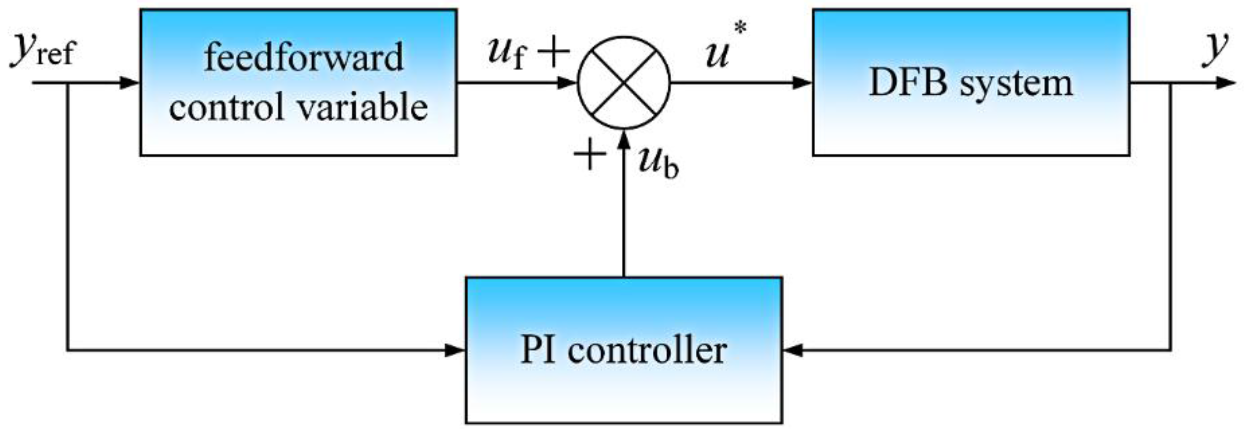
2.1. Introduction of Differential Flatness-Based Theory

The DFB theory with respect to non-linear system was presented by Fliess et al. [19,20] in the 1990s. The concept of flatness-based system aims to reveal the existence of structural form for the characteristics of nonlinear systems. Flatness-based theory is an effective nonlinear approach to designing controllers for nonlinear systems. The flatness property is used to control continuous nonlinear systems with good performance. The control strategy based on differential flatness-based theory shows robust dynamic performance during perturbations and disturbances [21,22].
According to DFB theory, a system is considered to be differentially flat if a set of variables (flat output components) can be found such that all state variable and input components can be determined from these output components and its finite order differentiation without any integration [23].
A non-linear dynamic system is shown in Equation (1):
x ˙ = f ( x , u )
where x is the state vector and u is the input vector (xRn and uRm). The system is considered to be differentially flat if an output yRm can be expressed as Equation (2):
{ x = X ( y ,   y ˙ , y ¨ ,   y ( k ) ) u = U ( y ,   y ˙ , y ¨ ,   y ( l ) )
where rank(X) = n, rank(U) = m; j, k, and l are positive integers; y is called the flat output. The selection of output y is not constant with respect to the different practical requirement.
The core of control laws using differential flatness-based theory is realized in two main steps as follows:
(a)
Generation of the predicted reference trajectory: the desired reference state trajectory should be generated according to the flat output signals and then the corresponding controlled input trajectory is produced as the feedforward control variables;
(b)
Feedback compensation for tracking error: feedback compensation is used to adjust the tracking error caused by system uncertainty or external disturbances.
In the control system based on DFB theory, yref represents the desired flat output and the tracking error is Δy, where Δy = yyref. The system could be linearized at Δy = 0 [24] and keep stable at Δy = 0 through error compensation controller. The structural diagram of a DFB control system is shown in Figure 1.
In Figure 1, a PI controller is used as the error compensation controller; uf and ub represent the feedforward control variable and feedback compensation variable, respectively; u* means the ultimate reference control input.

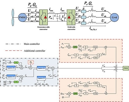
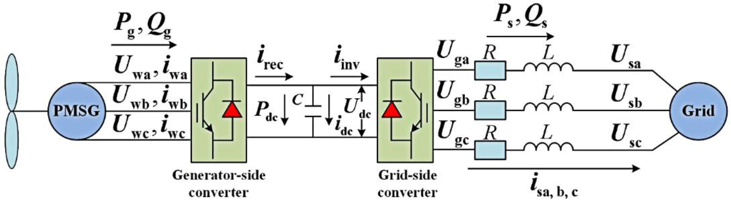
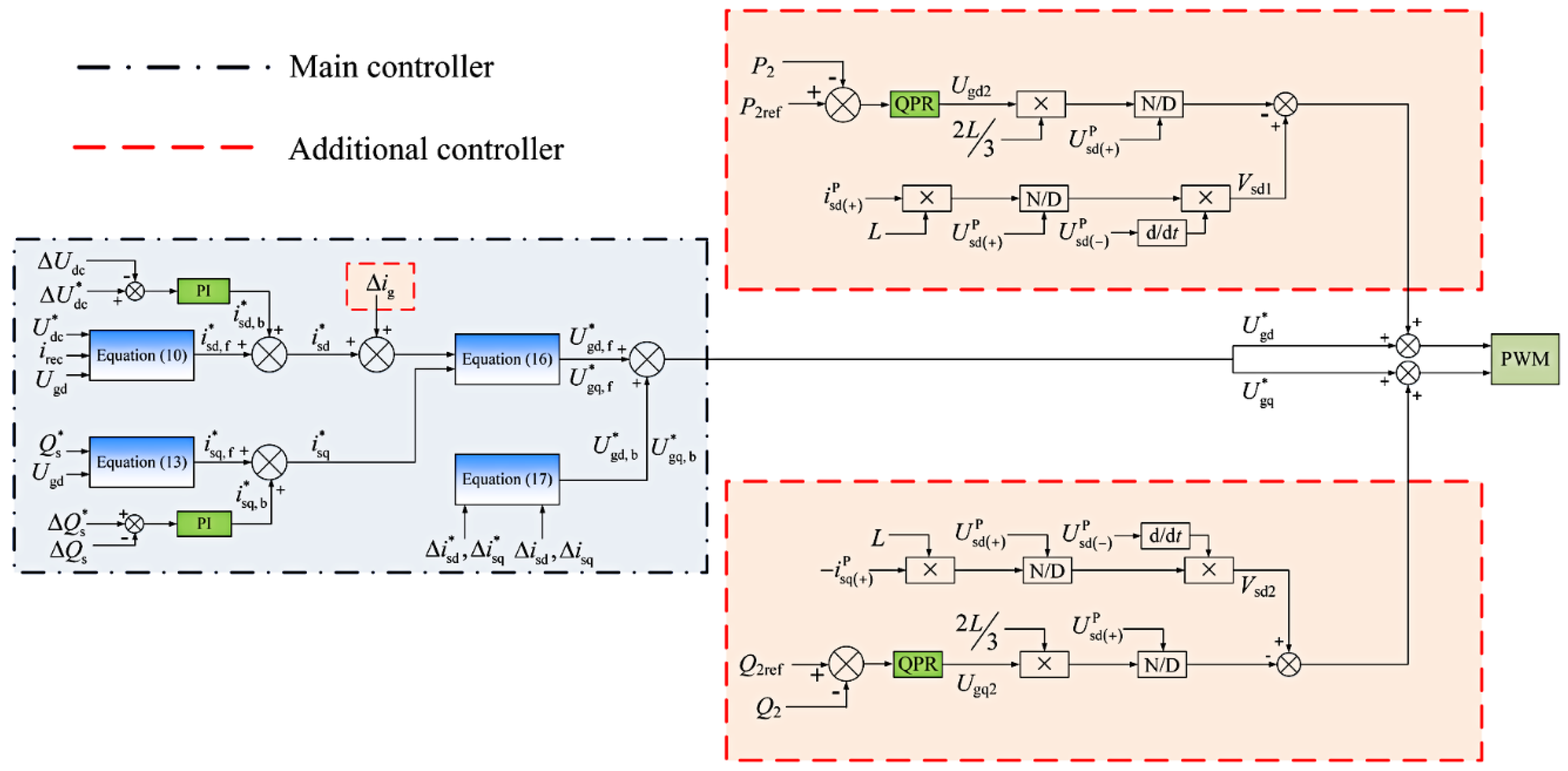
2.2. Differential Flatness-Based Description of PMSG Grid-Side System

The topological structure of PMSG-based wind turbine system is shown in Figure 2. The PMSG is directly driven by a wind turbine and connected to the grid by back-to-back VSCs [25].
In Figure 1, Uga, Ugb, Ugc are the three-phase voltages of the grid side of the grid-side converter. Usa, Usb, Usc represent the three-phase voltages of the grid. isa, isb, isc are the three-phase currents of the grid side of the grid-side converter. irec and iinv represent the generator-side input current and grid-side output current respectively, Udc and idc are the voltage and current in DC-link.
Based on the PMSG system structure shown in Figure 2, the mathematical model of the grid-side voltage equations in synchronous rotating dq frame can be written as follows:
{ U sd = R i sd + L d i sd d t + U gd ω L i sq U sq = R i sq + L d i sq d t + U gq ω L i sd C d U dc d t = i rec i inv = i dc
where Usd, Usq, isd and isq stand for the grid voltage and current components represented in the dq reference frame, respectively. Ugd and Ugq represent the VSC ac-side voltage components in the dq reference frame.
By orienting the d-axis along the grid voltage, Ugq equals zero. The active and reactive power at the grid-side VSC can be written in the synchronous reference frame as:
{ P s = 3 2 U gd i sd Q s = 3 2 U gd i sq
When the loss of power is ignored, Udc can be expressed as:
U dc = 3 2 U gd i sd i dc
Then the dynamic expression of Udc is:
C d U dc d t = 3 2 U gd i sd U dc
In this paper, the grid-side converter is used to control DC voltage and reactive power. Therefore, Udc and isq are selected as the state vectors (x1, x2)T; Ugd and Ugq are input vectors (u1, u2)T; isd and isq are selected as the output vectors (y1, y2)T.
According to Equations (1)–(6), x and u can be expressed as the function of y as:
x = [ U dc i sq ] = [ 3 2 U gd i dc i sd i sq ] = Y 1 ( y 1 ,   y 2 )
u = [ U gd U gq ] = [ U sd R i sd L i ˙ sd + ω L i sq U sq R i sq L i ˙ sq ω L i sd ] = Y 2 ( y 1 ,   y ˙ 1 ,   y 2 ,   y ˙ 2 )
According to the function relationship described in Equations (7) and (8), the grid-side VSC system of a PMSG can be regarded as a DFB system.

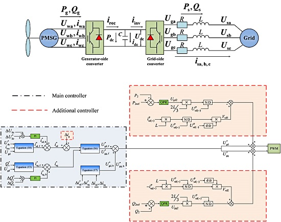
2.3. Design of Differential Flatness-Based Controller for Grid-Side Voltage Source Converter

The feedforward reference control input can be generated by the mathematical model of VSC in Equation (1), while the feedback control loop is adopted to compensate the flat output error caused by disturbances and uncertainties of the system model. The designed DFB controller applies the cascade double closed-loop control structure where the feedforward input control is more important than the feedback compensation control, which is different from the conventional PI controller.
In the design of outer loop control, Udc and isq are chosen as the flat output according to the control objective, namely, y = [y1, y2]T = [Udc, isq]T. According to the Udc modelling in Equation (3), the active power transmission model from generator-side to grid can be expressed as:
U dc C d U dc d t = P g P s = U dc i rec 3 2 U gd i sd
where Pg and Ps represent the generator-side active power and the grid-side active power respectively.
In the feedforward control of the differential flatness-based theory, the desired feedforward control reference value is obtained via the flat output nominal value [26]. According to Equation (9), the feedforward control reference value of outer loop active component can be calculated as:
i sd , f * = 2 3 U gd ( U dc * i rec C U dc * d U dc * d t )
where U*dc is the DC voltage rated value.
Based on DFB theory, the DC voltage error ΔUdc = UdcU*dc. In order to compensate the system disturbance impact, the feedback control reference value of the active component is calculated by the introduction of the following PI control regulator:
i sd ,   b * = ( k p 1 + k i 1 s ) ( Δ U dc * Δ U dc )
where kp1 and ki1 are PI control parameters. To eliminate the error of Udc, ΔU*dc = 0, according to Equations (10) and (11), the total active component reference value of the flatness-based outer loop control can be expressed as:
i sd * = i sd ,   f * + i sd ,   b *
For the reactive component reference value i*sq, the feedforward control reference value of outer loop reactive component can be written in Equation (13):
i sq ,   f * = 2 Q s * 3 U gd
where Q*s is the rated value of the reactive power. Similarly, the error of the reactive power is ΔQs = QsQ*s and the feedback control reference value of reactive component can be calculated by Equation (14):
i sq ,   b * = ( k p 2 + k i 2 s ) ( Δ Q s * Δ Q s )
where kp2 and ki2 are PI control parameters, ΔQ*s = 0. The total reactive component reference value of flatness-based outer control can be calculated as:
i sq * = i sq ,   f * + i sq ,   b *
In the design of inner loop control, the feedforward control reference values U*gd, f and U*gq, f are:
{ U gd ,   f * = U sd R i sd * L d i sd * d t + ω L i sq * U gq ,   f * = U sq R i sq * L d i sq * d t ω L i sd *
Similar to the design procedure in outer loop control, the error of isd and isq can be described as Δisd = isdi*sd, Δisq = isqi*sq. Based on the linearization of Equation (16) at Δisd = Δisq =0, the feedback control reference values U*gd, b and U*gq, b can be expressed as:
{ U gd ,   b * = ( k p 3 + k i 3 s ) ( Δ i sd * Δ i sd ) + ω L Δ i sq U gq ,   b * = ( k p 4 + k i 4 s ) ( Δ i sq * Δ i sq ) ω L Δ i sd
where kp3, kp4, ki3, ki4 are PI control parameters, and Δi*sd = Δi*sq = 0. According to Equations (16) and (17), the total control reference value of flatness-based inner loop control can be calculated by Equation (17):
{ U gd * = U gd ,   f * + U gd ,   b * U gq * = U gq ,   f * + U gq ,   b *
In summary, the main DFB control system diagram of PMSG grid-side VSC is shown in Figure 3.

3. Design of the Additional Controller

There are two main control objects in the proposed additional control scheme: (1) a compensation control loop to simultaneously restrain the oscillation of grid-side active power and reactive power without the requirement of respectively calculating the inner current control references for different control objectives; and (2) a feedforward modified control factor reflecting the DC-link power imbalance in the traditional DC voltage controller to reduce DC-link overvoltage during grid fault conditions.

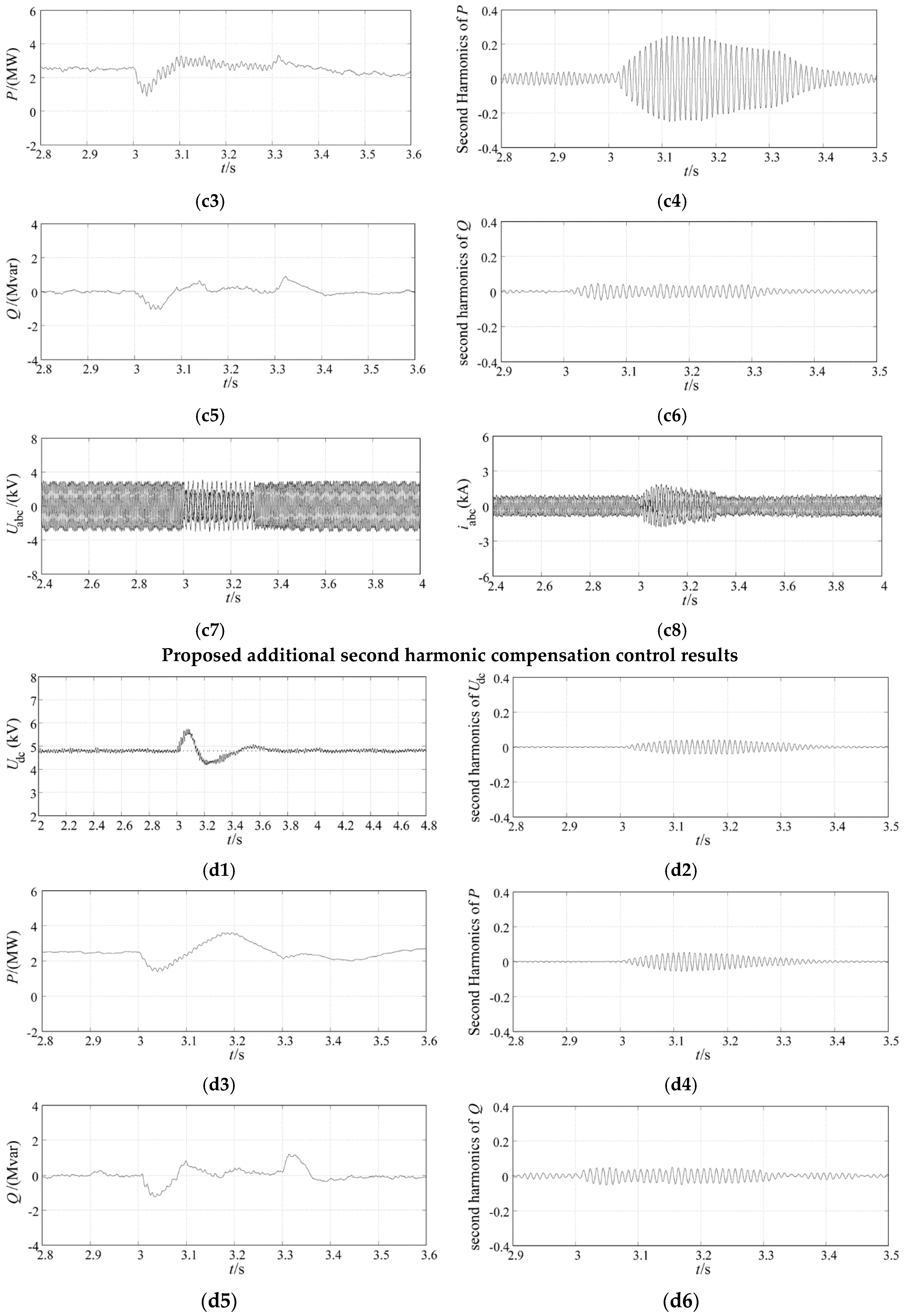
3.1. Compensation Controller to Restrain the Second Harmonic Oscillations of Transmission Power

During asymmetrical faults, the Uga, Ugb, Ugc and isa, isb, isc, can be decomposed into positive sequence and negative sequence components during asymmetrical faults:
{ U g = U gdq P + U gdq N = U g α β e j ω t + U g α β e j ω t i s = i sdq P + i sdq N = i s α β e j ω t + i s α β e j ω t
where Ugαβ = U + jU and isαβ = i + ji are the voltage and current components in α-β stationary coordinate system; UPgdq = UPgd + jUPgq and iPsdq = iPsd + jiPsq denote the voltage and current components in positive anticlockwise rotating coordinate system; UNgdq = UNgd + juNgq and iNsdq = iNsd + jiNsq represent the voltage and current components in negative clockwise rotating coordinate system.
According to Equation (19) and Figure 4, the relationship between the positive sequence components of Usa, b, c, Uga, b, c and isa, b, c and the negative sequence components of Usa, b, c, Uga, b, c and isa, b, c are:
{ U sdq P = U sdq N e j 2 ω t ,   U sdq N = U sdq P e j 2 ω t U gdq P = U gdq N e j 2 ω t ,   U gdq N = U gdq P e j 2 ω t i sdq P = i sdq N e j 2 ω t ,   i sdq N = i sdq P e j 2 ω t
Based on the transformed relationship of the voltages and currents in Equations (19) and (20) between different sequences of rotating coordinates, Usdq, Ugdq and isdq can be entirely transformed into a positive sequence rotating coordinate:
{ U sdq = U sdq ( + ) P + U sdq ( ) N = U sdq ( + ) P + U sdq ( ) P e j 2 ω t U gdq = U gdq ( + ) P + U gdq ( ) N = U gdq ( + ) P + U gdq ( ) P e j 2 ω t i sdq = i sdq ( + ) P + i sdq ( ) N = i sdq ( + ) P + i sdq ( ) P e j 2 ω t
where the subscripts “(+)” and “(−)” represent the positive sequence and negative sequence, respectively; superscripts “P” and “N” denote being in a positive or negative sequence rotating frame, respectively; the negative sequence components in the negative rotating frame UNsdq(−), UNgdq(−), and iNsdq(−) are converted into the ones in positive rotating frame as UPsdq(−)ej2ωt, UPgdq(−)ej2ωt and iPsdq(−)ej2ωt.
Due to the double-frequency characteristics of the transformation factor ej2ωt in Equations (20) and (21), the negative sequence components in the positive rotating frame are hence regarded as second harmonic components, whereas the positive sequence components in the positive rotating frame are DC components. Therefore, Usa, b, c, Uga, b, c and isa, b, c can be expressed as the sum of DC components and second harmonic components.
In order to control the second harmonic components of voltage and current independently, the double frequency voltage equations of PMSG grid-side VSC can be written as:
{ U sd ( ) P = R i sd ( ) P + L d i sd ( ) P d t + U gd ( ) P ω L i sq ( ) P U sq ( ) P = R i sq ( ) P + L d i sq ( ) P d t + U gq ( ) P + ω L i sd ( ) P
Based on the derivation of transmission power in [27,28], the active and reactive power in grid-side of PMSG during asymmetrical faults are:
{ P 0 = 3 2 ( U gd P I sd P + U gq P I sq P + U gd N I sd N + U gq N I sq N ) P c 2 = 3 2 ( U gd P I sd N + U gq P I sq N + U gd N I sd P + U gq N I sq P ) P s 2 = 3 2 ( U gd N I sq P U gq N I sd P U gd P I sq N + U gq P I sd N ) Q 0 = 3 2 ( U gd P I sq P U gq P I sd P + U gd N I sq N U gq N I sd N ) Q c 2 = 3 2 ( U gd P I sq N U gq P I sd N + U gd N I sq P U gq N I sd P ) Q s 2 = 3 2 ( U gq P I sq N + U gd P I sd N U gq N I sq P U gd N I sd P )
{ P s = P 0 + P c 2 cos ( 2 ω t ) + P s 2 sin ( 2 ω t ) Q s = Q 0 + Q c 2 cos ( 2 ω t ) + Q s 2 sin ( 2 ω t )
According to the VSC instantaneous power calculated in [29], six power components (P0, Pc2, Ps2, Q0, Qc2, Qs2) need to be regulated during asymmetrical faults, while only four current components (iPsd, iNsd, iPsq, iNsq) in the dq frame can be chosen as control variables. Therefore, the six power components cannot be regulated to the reference values without any special transformation for the transmission power equations. In this paper, the second harmonic components of grid-side active and reactive power are regarded as the sum of cosine harmonic components Pc2cos(2ωt), Qc2cos(2ωt) and the sum of sinusoidal harmonic components Ps2sin(2ωt), Qs2sin(2ωt) respectively, thus the total second harmonic components of P and Q can be calculated as:
P 2 = P c 2 cos ( 2 ω t ) + P s 2 sin ( 2 ω t ) = 3 2 { U gd ( + ) P ( i sd ( ) N cos ( 2 ω t ) + i sq ( ) N sin ( 2 ω t ) ) + U gq ( + ) P ( i sq ( ) N cos ( 2 ω t ) i sd ( ) N sin ( 2 ω t ) ) + i sd ( + ) P ( U gd ( ) N cos ( 2 ω t ) + U gq ( ) N sin ( 2 ω t ) ) + i sq ( + ) P ( U gq ( ) N cos ( 2 ω t ) U gd ( ) N sin ( 2 ω t ) ) } = 3 2 ( U gd ( + ) P i sd ( ) P + U gq ( + ) P i sq ( ) P + U gd ( ) P i sd ( + ) P + U gq ( ) P i sq ( + ) P )
Q 2 = Q c 2 cos ( 2 ω t ) + Q s 2 sin ( 2 ω t ) = 3 2 { U gd ( + ) P ( i sq ( ) N cos ( 2 ω t ) i sd ( ) N sin ( 2 ω t ) ) U gq ( + ) P ( i sd ( ) N cos ( 2 ω t ) + i sq ( ) N sin ( 2 ω t ) ) + i gd ( + ) P ( U gd ( ) N sin ( 2 ω t ) U gq ( ) N cos ( 2 ω t ) ) + i gq ( + ) P ( U gd ( ) N cos ( 2 ω t ) + U gq ( ) N sin ( 2 ω t ) ) } = 3 2 ( U gd ( + ) P i sq ( ) P + U gd ( ) P i sd ( + ) P U gq ( + ) P i sd ( ) P U gq ( ) P i sd ( + ) P )
In order to restrain the oscillation of the grid-side P and Q, the second harmonic components P2 and Q2 are considered to be the control variables and a compensation control loop for second harmonic components is designed according to Equation (22), which can be seen as the supplementary part to the main controller.
In this paper, d-axis voltage component depicts the grid-side voltage amplitude, which means UPsq(+) = 0. Typically, the amplitude of negative sequence voltage component in positive rotating coordinate fluctuates slightly around 0. Therefore, Equations (25) and (26) can be simplified as:
{ P 2 = 3 2 ( U gd ( + ) P i sd ( ) P + U gd ( ) P i sd ( + ) P ) Q 2 = 3 2 ( U gd ( + ) P i sq ( ) P + U gd ( ) P i sq ( + ) P )
In order to obtain the control variables defined by P2 and Q2, Equation (27) can be differentiated as:
{ d P 2 d t = 3 2 ( U gd ( + ) P d i sd ( ) P d t + U gd ( ) P d i sd ( + ) P d t   + i sd ( + ) P d U gd ( ) P d t + i sd ( ) P d U gd ( + ) P d t ) d Q 2 d t = 3 2 ( U gd ( + ) P d i sq ( ) P d t + U gd ( ) P d i sq ( + ) P d t + i sq ( + ) P d U gd ( ) P d t + i sq ( ) P d U gd ( + ) P d t )
where the positive sequence components UPgd(+), iPsd(+) and iPsq(+) in positive rotating coordinate are DC components, the derivation of which are zero and thus Equation (28) can be simplified as:
{ d P 2 d t = 3 2 ( U gd ( + ) P d i sd ( ) P d t + i sd ( + ) P d U gd ( ) P d t ) d Q 2 d t = 3 2 ( U gd ( + ) P d i sq ( ) P d t + i sq ( + ) P d U gd ( ) P d t )
According to the differentiated components of P2 and Q2 in Equation (29), Equation (22) can be rewritten and the control equation of P2 and Q2 can be expressed as:
{ U gd ( ) P = L I sd ( + ) P U sd ( + ) P d U sd ( ) P d t + U sd ( ) P R I sd ( ) P + ω L I sq ( ) P 2 L 3 U sd ( + ) P d P 2 d t U gq ( ) P = L I sq ( + ) P U sd ( + ) P d U sd ( ) P d t U sq ( ) P + R I sd ( ) P + ω L I sd ( ) P 2 L 3 U sd ( + ) P d Q 2 d t
where UPgd(−) and UPgq(−) are the second harmonic compensation controlled voltage variables in the optimal control strategy.
In the compensation controller described by Equation (30), the key point is the adoption of an optimal approach which can effectively control P2 and Q2. In normal control strategies, a PI controller is usually used, the disadvantage of which is that it can only trace DC components. Therefore, the zero steady-state control error of the second harmonic components P2 and Q2 cannot be achieved through PI control function. The basic functionality of the proportional resonant (PR) controller is to realize zero steady-state error control for AC signals at a specific resonant frequency. However, the PR controller is difficult to realize in practical engineering and its stability decreases during disturbances because of the narrow bandwidth. To overcome the disadvantages of PI and PR controllers, the quasi proportional resonant (Quasi-PR) controller [30,31] is employed in this paper to design the second harmonic compensation control loop.
The Quasi-PR controller can achieve zero steady-state error tracking for signals of a selected frequency, which is similar to PR controller. Furthermore, a Quasi-PR controller can still achieve zero steady-state error during grid disturbances because of its relatively wide bandwidth, such as asymmetrical faults in grid, which improves the drawbacks of PR controller [30,31]. Therefore, the Quasi-PR controller is adopted to control the double frequency components P2 and Q2 in this paper. The typical Quasi-PR controller is defined as:
G ( s ) = K p + K r 2 ω c s s 2 + 2 ω c s + ω R 2
where Kp and Kr represent the proportional coefficient and the resonant coefficient respectively; ωR and ωc are the resonant frequency and cut-off frequency. In this paper, ωR is set as twice the fundamental grid frequency to reduce the double frequency fluctuation of active power and reactive power in grid.
To describe the optimal control structure clearly, Equation (30) can be described as:
{ U gd ( ) P = V gd 2 L 3 U sd ( + ) P U gd 2 U gq ( ) P = V gq 2 L 3 U sd ( + ) P U gq 2
{ V gd = L i sd ( + ) P U sd ( + ) P d U sd ( ) P d t + U sd ( ) P R i sd ( ) P + ω L i sq ( ) P = V sd 1 + ( U sd ( ) P R i sd ( ) P + ω L i sq ( ) P ) V gq = L i sq ( + ) P U sd ( + ) P d U sd ( ) P d t U sq ( ) P + R i sd ( ) P + ω L i sd ( ) P = V sd 2 + ( U sq ( ) P + R I sd ( ) P + ω L I sd ( ) P )
{ V sd 1 = L i sd ( + ) P U sd ( + ) P d U sd ( ) P d t V sd 2 = L i sq ( + ) P U sd ( + ) P d U sd ( ) P d t
Ugd2 and Ugq2 can be designed according to Quasi-PR control principle as follows:
{ U gd 2 = ( K p + K r 2 ω c s s 2 + 2 ω c s + ω R 2 ) ( P 2 ref P 2 ) U gq 2 = ( K p + K r 2 ω c s s 2 + 2 ω c s + ω R 2 ) ( Q 2 ref Q 2 )
In Equations (33) and (34), the components in brackets are included in the main control procedure and thus omitted in the compensation control loop; Vsd1 and Vsd2 are regarded as the compensation voltage components; In Equation (35), P2 and Q2 are the actual second harmonic components of active and reactive grid-side power, which are obtained through bandpass filter; P2ref and Q2ref represent the reference values of P2 and Q2 respectively, and P2ref = Q2ref = 0.
According to the analysis and design in Section 3.1, in order to restrain the fluctuation of DC voltage and transmission power in PMSG system under asymmetric grid fault conditions, an additional controller based on Equations (29)–(34) is added to the main DFB controller in of PMSG grid-side VSC.

3.2. Control Strategy to Reduce DC-Link Overvoltage

In order to restrain DC voltage swell during grid-side faults, a feedforward compensational control term reflecting the power imbalance on the two sides of DC-link is added to the traditional DC voltage control loop.
The regulation for DC voltage is accomplished through the control of d-axis current isd [32]. During grid faults, the overvoltage would happen in the DC-link caused by the imbalance of generator-side active power and grid-side active power. In traditional DC voltage control strategy, the regulation speed of isd cannot satisfy the requirements of DC voltage stability during grid faults. In this paper, an additionally compensational signal reflecting the power imbalance on the two sides of DC-link is added to the grid-side DC voltage controller to improve the dynamic characteristics of DC voltage regulator.
The dynamic model of transmission active power on DC side can be represented by the following equation as:
C U dc d U dc d t = P g P s
where Pg and Ps denote the generator-side active power and grid-side active power, respectively.
In order to compensate the power imbalance, the compensational active power can be written as ΔP = PsPg. According to P calculated in Equation (4), the additionally compensational signal can be expressed as:
Δ i g = 2 ( P s P g ) 3 U s
where Δig represents the additionally compensational current signal, which is combined with the main DFB outer loop control output i*sd to generate the new modified d-axis current reference value.
According to the description and analysis of the proposed optimal control schemes, the overall control block diagram of optimal control scheme is shown in Figure 5. In the presented optimal integrated control scheme, the main and additional controllers jointly have an improved effect on the dynamic response characteristics and fault-tolerance capability of PMSG wind power systems.

4. Simulation Results

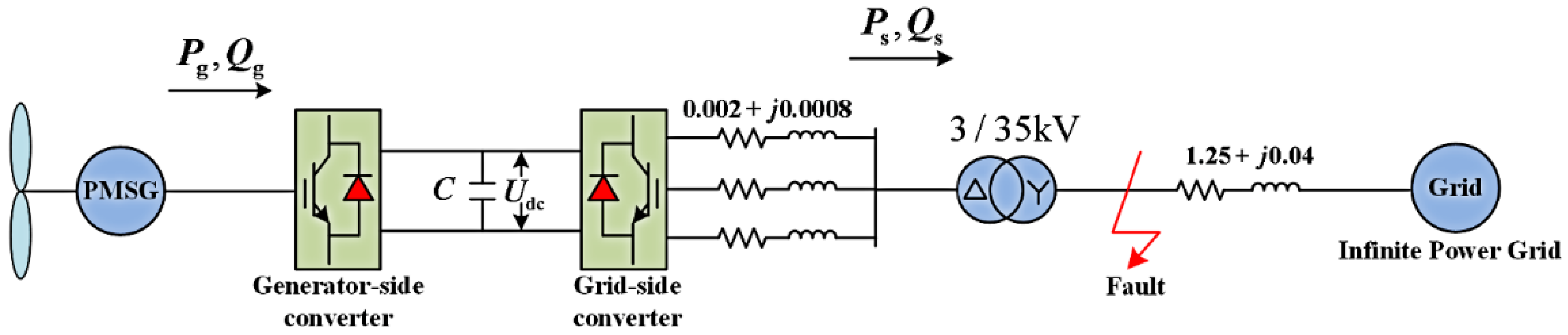
4.1. Simulation Model Description
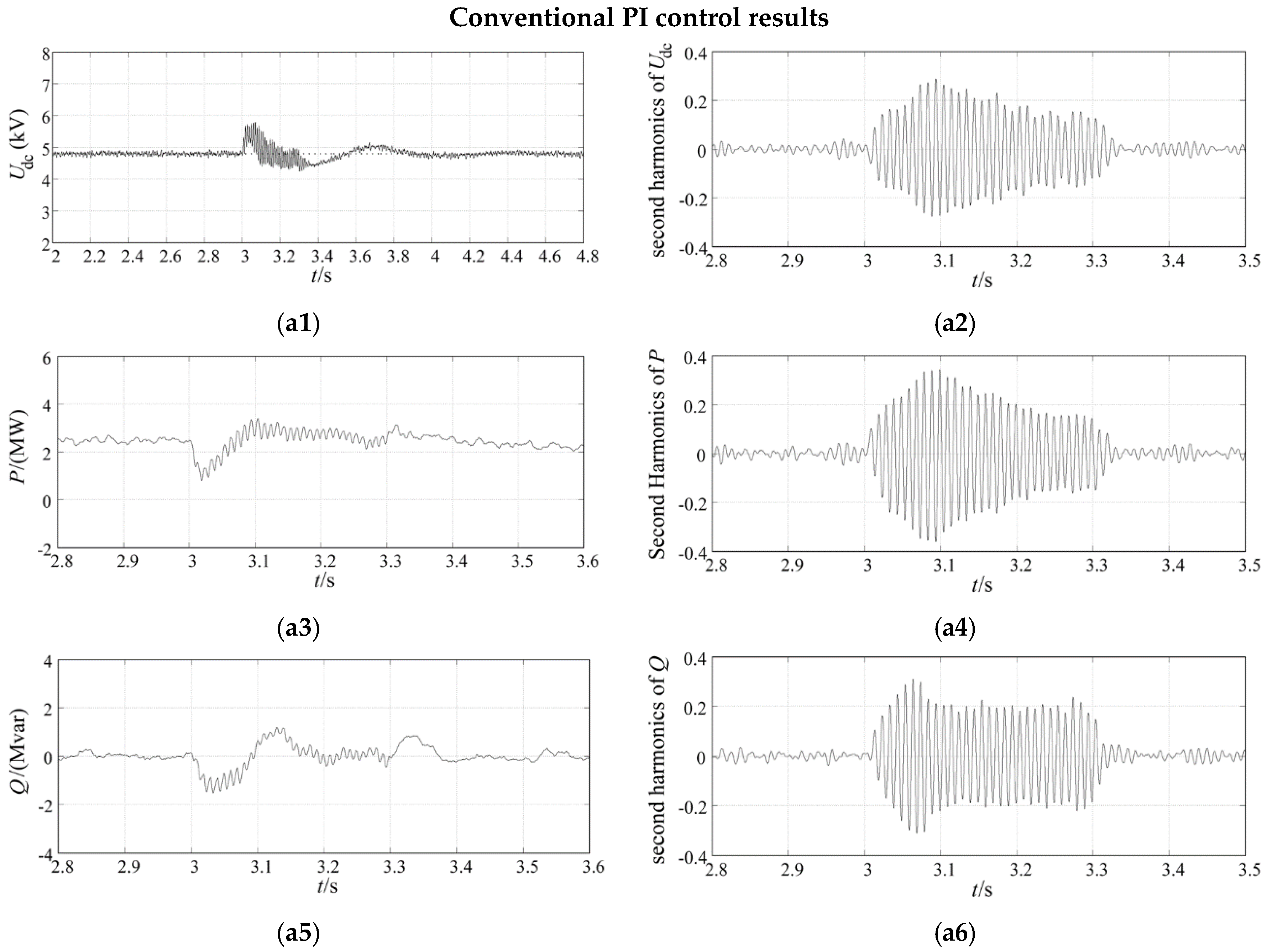
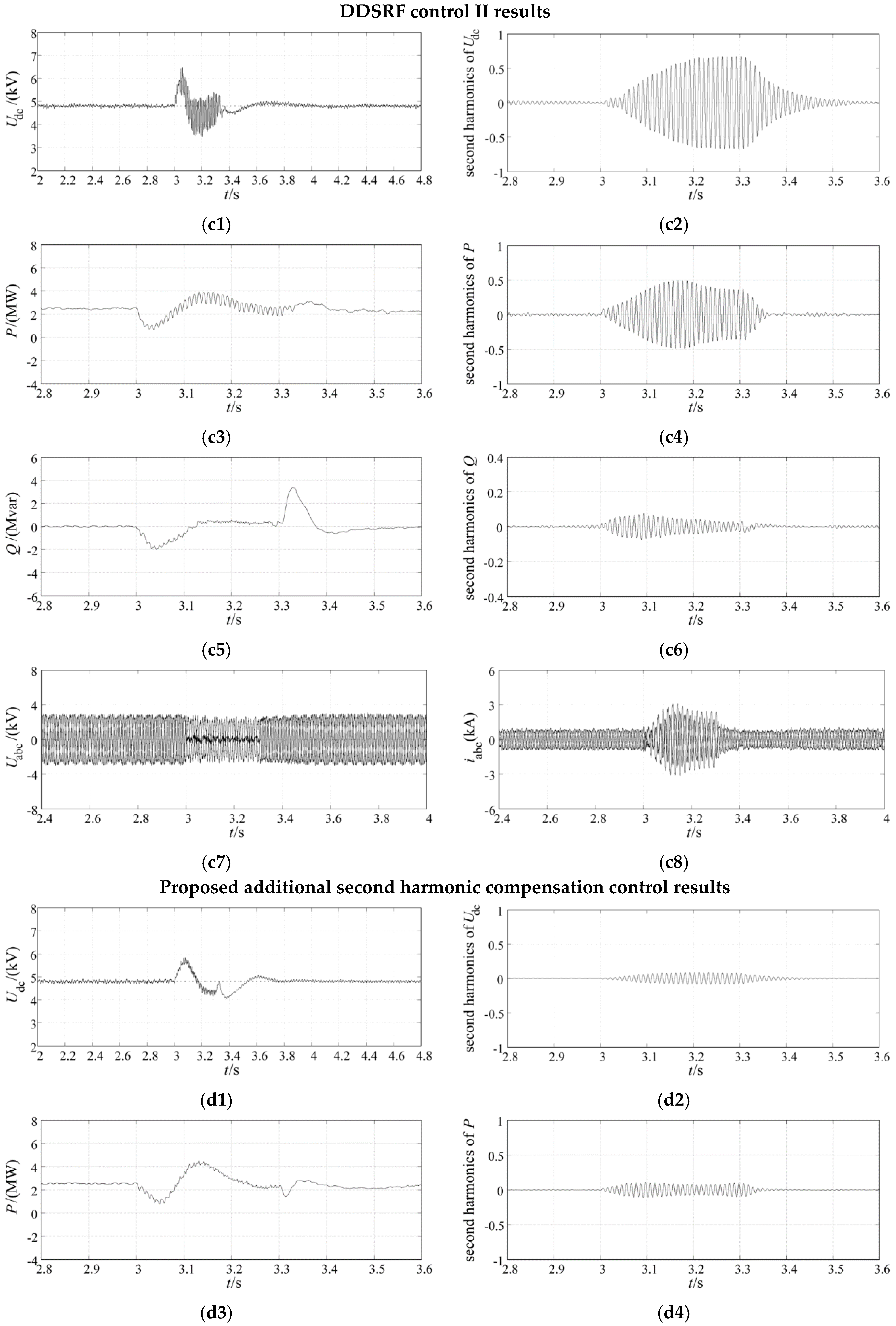
To verify the effectiveness of the proposed optimal control strategy, the overall structure of PMSG-based wind power system for simulation is shown in Figure 6. Here, the grid-side converter is connected to an infinite grid through a three-phase 3.0/35.0 kV transformer. The parameters of wind turbine, PMSG, converter and transmission system are listed in Table 1, Table 2 and Table 3, respectively. Simulations have been carried out using the PSCAD/EMTDC software. The control effects of traditional double-loop PI control strategy and the proposed optimal control strategy are analyzed and compared via two grid-side simulating asymmetrical fault conditions.

4.2. Cases Studies

In the simulations, two asymmetrical grid fault cases at the high-voltage side of transformer are emulated to verify the effectiveness of the proposed optimal control scheme compared with the traditional double-loop PI control strategy and the DDSRF (decoupled double synchronous reference frame) current control method. A single-phase-grounding grid fault and a phase-to-phase grid fault are simulated at the high-voltage side of the transformer in Case 1 and Case 2, respectively. In each case, the PMSG wind power system performances during the asymmetrical faults are analyzed to test the control effect of the proposed optimal control scheme.

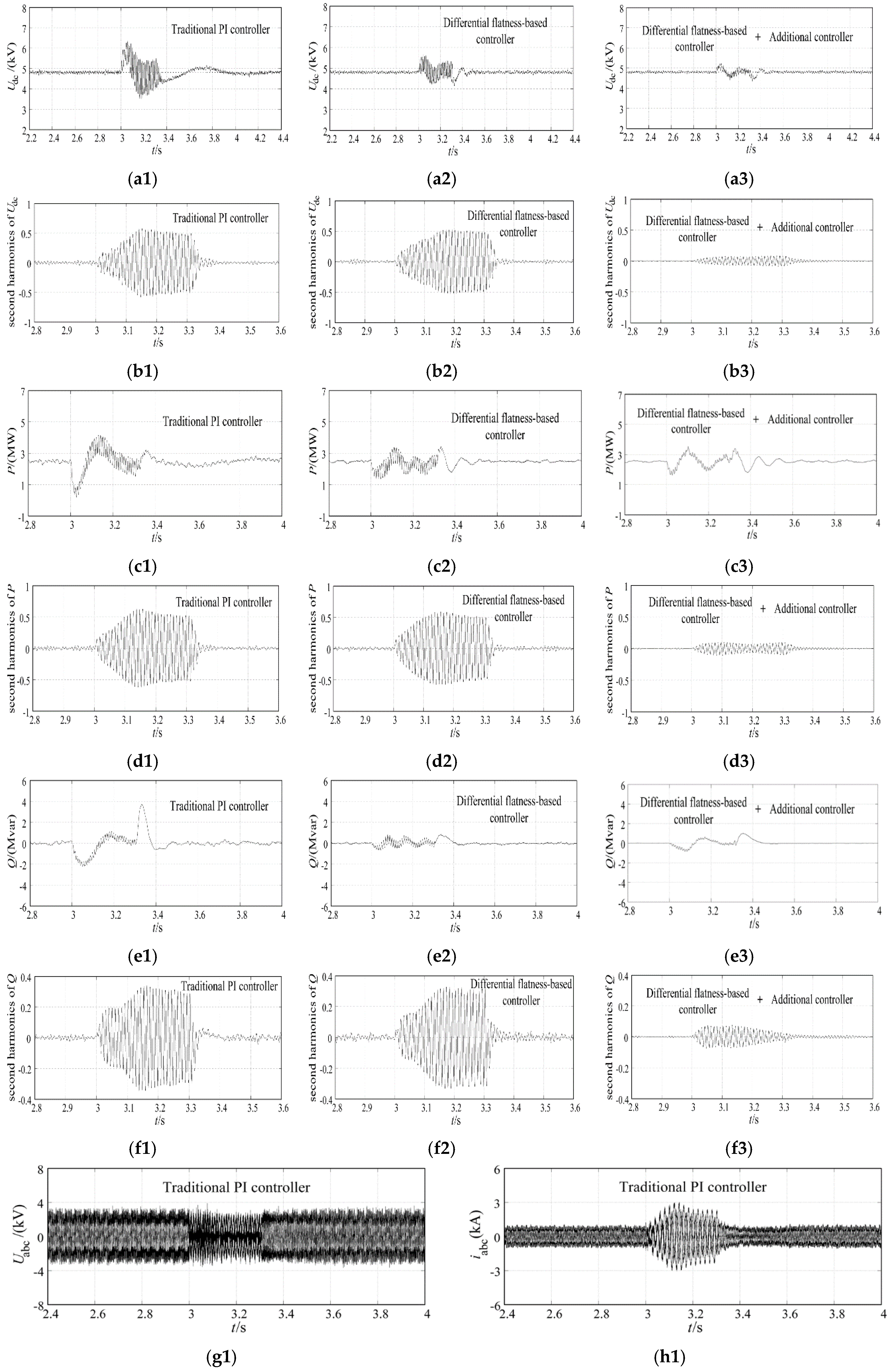
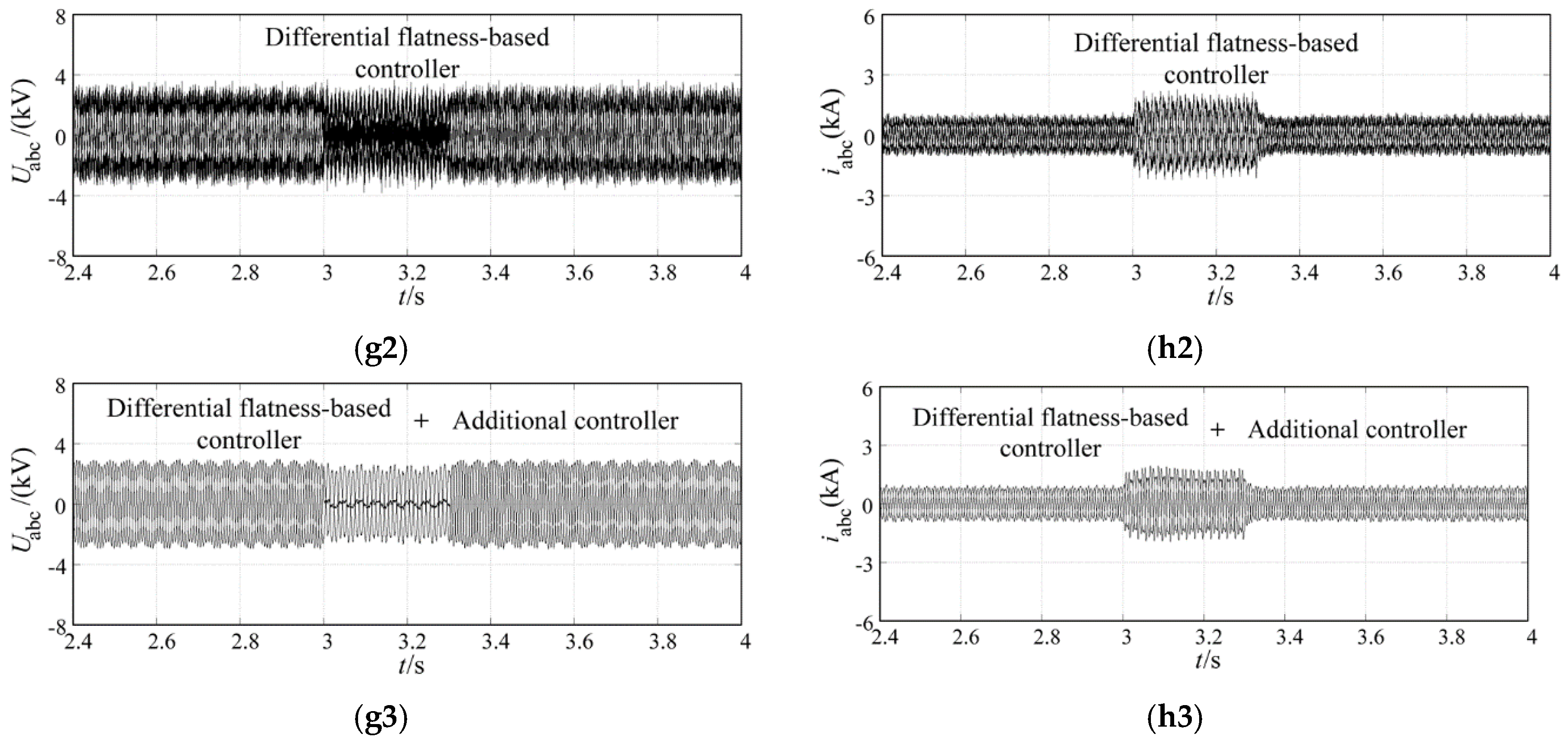
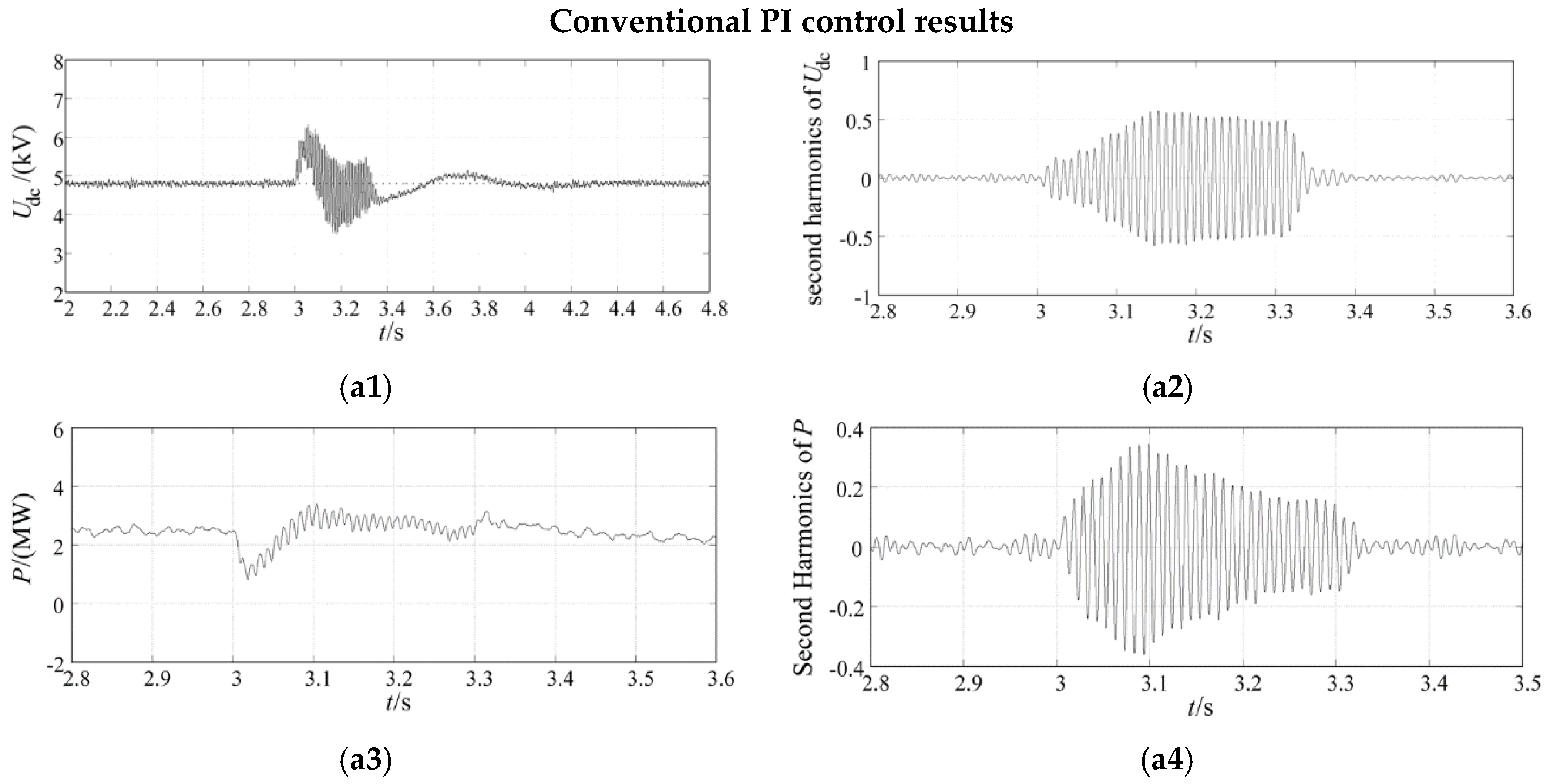
4.2.1. Case 1: Single-Phase-to-Ground Short-Circuit Grid Fault

A temporary single-phase-to-ground fault is set at the high-voltage side of the transformer. Wind speed is set to 10 m/s and constant in the simulation; the fault occurs at t = 3 s and it’s cleared at t = 3.3 s, which lasts 300 ms. The simulation step time is 50 μs and the total simulation time is 10 s. Simulation results are shown in Figure 7.
In the simulation results below, Figure 7a1–h1 is the simulation results when the traditional PI controller is used; Figure 7a2–h2 shows the simulation results when the differential flatness-based main controller is adopted independently; Figure 7a3–h3 shows the simulation results when the differential flatness-based main controller and the additional controller are used together.
Figure 7a1–b3 shows the simulation results about DC-link voltage when the traditional PI controller or the differential flatness-based controller without and with the additional controller is used. When traditional PI controller is used, DC voltage increases seriously and contains a high content of second harmonic components. After the fault is cleared at t = 3.3 s, DC voltage recovers to the rated value after t = 3.9 s with undesired oscillation. Compared to the results with traditional control, the DC-link voltage increase with the flatness-based controller can be reduced when the grid fault happens while the overvoltage and the oscillation still exist.
For the process after the clearance of fault, DC voltage with the flatness-based controller recovers in 0.2 s and the recovery process is smooth and without fluctuations. When the proposed additional controller is used together with the flatness-based control, DC-link overvoltage is almost eliminated and the second harmonic oscillation of DC voltage is reduced. After the fault is cleared at t = 3.3 s, DC voltage can be adjusted to the reference value rapidly and smoothly.
For the results in Figure 7c1–f3, the performances of grid-side active power and reactive power with different controllers are presented. It can be seen that the active and reactive power with flatness-based controller decrease less when the fault occurs and minor fluctuations occur during the grid fault compared with the results under traditional PI control. The oscillation of active power and reactive power can be seen when either the traditional PI control or the flatness-based control is adopted. With the additional controller, the second harmonic oscillation of active power and reactive power shown in Figure 7c3,e3 are restrained simultaneously. After the fault is removed at t = 3.3 s, the active power and reactive power with the proposed controller recovers more rapidly and steadily than with the traditional control.
From Figure 7g1,h1, the waveforms of the grid-side converter voltage and current are seriously distorted, and the current fluctuates significantly under the traditional PI control strategy. When the flatness-based controller is adopted, it can be seen from Figure 7g2,h2 that the current fluctuation is reduced. However, the voltage and current harmonics still exist, which causes continuous pulsations of the transmission power. After the second harmonic compensation is activated via the additional controller, Figure 7g3,h3 shows that the waveforms of the voltage and current become smoother and less distorted.
In order to show the improvement of the proposed additional second harmonic compensation control compared with other general used methods, we have adopted the DDSRF [33] method to design a DDSRF-based dual-PI controller [4,34] to enhance the effectiveness and the advantage of the proposed harmonic compensation method by comparative simulations.
In the DDSRF-based dual-PI current controller, the current reference of different control targets is calculated according to Equation (23). Due to the limited degrees of freedom, the current references have to be calculated with the different control targets of restraining active power second harmonics or reducing reactive power second harmonic oscillations, respectively. In the simulations, the DDSRF-based control with the target to restrain the second harmonic components of active power is defined as "DDSRF control I"; the DDSRF-based control with the target to restrain the second harmonic components of reactive power is defined as “DDSRF control II”. The proposed harmonic compensation controller is used independently without the proposed differential flatness-based main controller and the additional DC voltage modification controller.
In the simulation plots below, Figure 8a1–a8 is the simulation results when the conventional PI controller is used; Figure 8b1–b8 show the simulation results when the DDSRF control I is adopted; Figure 8c1–c8 is the simulation results when the DDSRF control II is used; Figure 8d1–d8 is the simulation results when the proposed additional second harmonic compensation control is applied independently without the proposed flatness-based main controller and the additional DC voltage modification controller.
As can be seen from Figure 8b1–b6, the second harmonic pulsations of active power and DC voltage decrease to a very low level with the regulation effect of DDSRF control I. As the current reference is calculated to restrain the second harmonics of active power in DDSRF control I, the second harmonic oscillation in reactive power cannot be effectively reduced.
Figure 8c1–c6 shows that the second harmonic pulsations of reactive power are reduced to a very low level with the regulation effect of DDSRF control II. However, the second harmonic fluctuations of active power and DC voltage still exist.
As shown in Figure 8d1–d6, the second harmonic oscillations of active power, reactive power and DC voltage can be simultaneously restrained to a very low level by the control effect of the proposed additional harmonic compensation controller.
According to the simulation results of voltages and currents under different control schemes, the waveforms of the voltages and currents with the proposed harmonic compensation controller become smoother and less distorted.

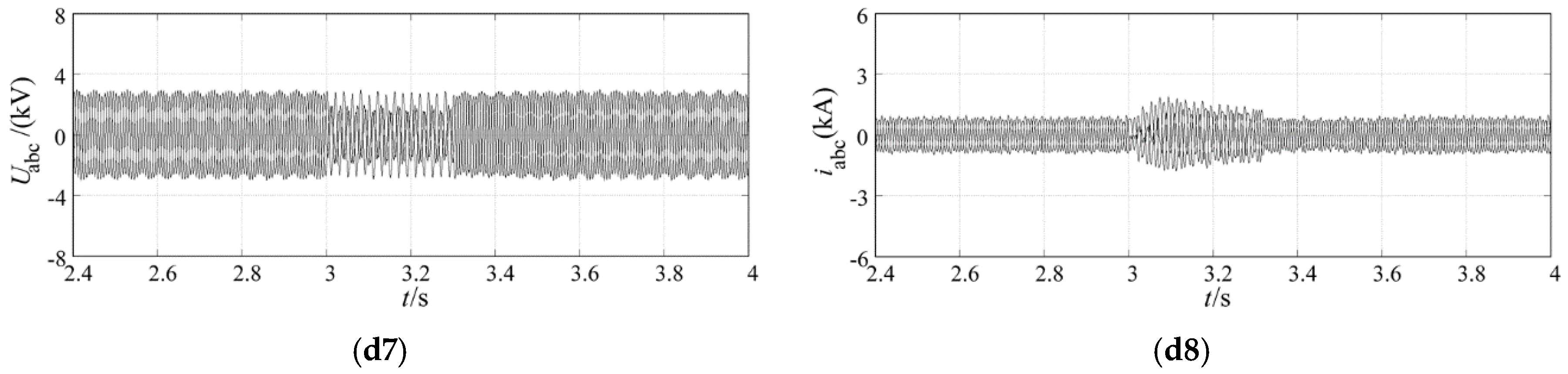
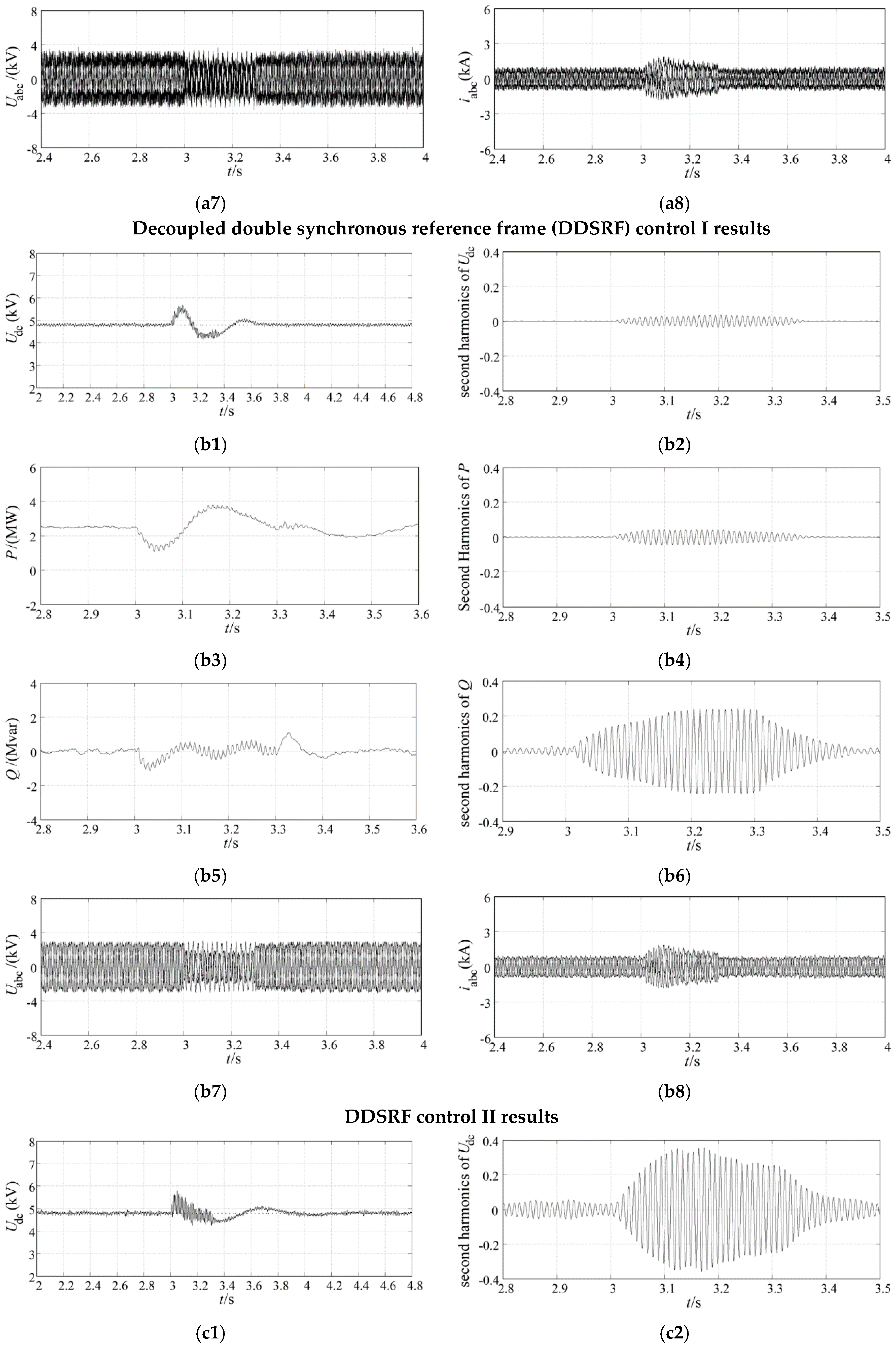
4.2.2. Case 2: Phase-to-Phase Short-Circuit Grid Fault

A temporary phase-to-phase fault is emulated at the high-voltage side of the PMSG wind power system. Wind speed is constant at 10 m/s in the simulations; the fault happens at t = 3 s and it’s cleared at t = 3.3 s, so it lasts 300 ms. The simulation step time is 50 μs and the total simulation time is 10 s. Simulation results are shown in Figure 9.
In the simulation results below, Figure 9a1–h1 is the simulation results when the traditional PI controller is used; Figure 9a2–h2 expresses the simulation results when the differential flatness-based main controller is adopted independently; Figure 9a3–h3 shows the simulation results when the differential flatness-based main controller and the additional controller are used together.
The simulation results of DC-link voltage with different controllers are presented in Figure 9a1–b3. As can be seen in Figure 9a1,b1, the DC voltage under the traditional PI control increases seriously with a large amplitude and oscillates sharply. After the fault is cleared at t = 3.3 s, the DC voltage takes about 1.0 s to recover to the rated value and a continuous fluctuation appears in the recovery process. When the flatness-based controller is adopted instead of traditional control, the DC-link overvoltage can be reduced and DC voltage recovers to the rated value at t = 3.5 s without fluctuations. However, the problem of DC voltage’s second harmonic oscillation cannot be solved by traditional control nor the flatness-based control. It can be observed in Figure 9a3,b3 that the DC voltage oscillations are effectively restrained by the harmonic compensation control, and the DC-link overvoltage is reduced to a minor extent with the additional DC-link feedforward control compared to the flatness-based control used alone. In the recovery process after the fault is removed, DC voltage is regulated back to the nominal value rapidly without fluctuations.
Figure 9c1–f3 describes the grid-side active power and reactive power performances with different control strategies. As shown in Figure 9c1,e1, the active and reactive power with traditional PI control fluctuate with a large amplitude during fault conditions. When the flatness-based controller is used, the active and reactive power display minor fluctuations during the grid fault. After the fault is removed at t = 3.3 s, the active power and reactive power with flatness-based controller are adjusted to the reference values with a rapid and smooth recovery while the power with traditional PI controller takes a longer recovery process to the rated values. Like with the traditional control, the flatness-based control cannot restrain the second harmonic oscillation of active power and reactive power. When the harmonic compensation controller is used, the continuous oscillation of active power and reactive power during grid fault can be effectively reduced at the same time.
As can be observed in Figure 9g1–g2 and h1–h2, the waveforms of the grid-side converter voltage and current are seriously distorted when the traditional control is used or the flatness-based controller is adopted independently. When the additional second harmonic compensation controller is used, Figure 9g3,h3 shows that the waveforms of the voltage and current become smoother and less distorted.
The phase-to-phase grid fault conditions are also simulated to show the improvement of the proposed additional second harmonic compensation control compared with the DDSRF-based dual-PI controller. In the simulations, the DDSRF-based control with the target to restrain the second harmonic components of active power is defined as “DDSRF control I”; the DDSRF-based control with the target to restrain the second harmonic components of reactive power is defined as “DDSRF control II”. The proposed harmonic compensation controller is used independently without the proposed differential flatness-based main controller and the additional DC voltage modification controller.
In the simulation plots below, Figure 10a1–a8 is the simulation results when the conventional PI controller is used; Figure 10b1–b8 shows the simulation results when the DDSRF control I is adopted; Figure 10c1–c8 is the simulation results when the DDSRF control II is used; Figure 10d1–d8 is the simulation results when the proposed additional second harmonic compensation control is applied independently without the proposed flatness-based main controller and the additional DC voltage modification controller.
The plots in Figure 10b1–b6 shows that the second harmonic components of active power and DC voltage decrease to a very low content with the regulation effect of DDSRF control I. As the current reference is calculated to restrain the second harmonics of active power in DDSRF control I, the second harmonic oscillation in reactive power cannot be restrained.
As can be seen in Figure 10c1–c6 the second harmonic pulsations of reactive power can be restrained with the regulation effect of DDSRF control II. However, the second harmonic fluctuations of active power and DC voltage still exist.
As shown in Figure 10d1–d6, with the regulation of the proposed additional harmonic compensation controller, the second harmonic oscillations of active power, reactive power and DC voltage can be all effectively restrained to a very low level.
From the simulation results of voltages and currents under different control schemes, the waveforms of the voltages and currents with the proposed harmonic compensation controller become smoother and less distorted.
According to the simulation results in Figure 8 and Figure 10, the improvement and effectiveness of the proposed additional second harmonic compensation control to simultaneously restrain the second harmonic pulsations of active power, reactive power and DC voltage without the need to respectively calculate current references of different control targets is validated compared with the conventional PI control and DDSRF-based dual-PI control. As can be seen in the simulation plots in Section 4.2, the integrated operation characteristics of PMSG-based wind power system under asymmetrical grid fault can be more improved and robust by the regulation of the harmonic compensation control together with the proposed flatness-based main controller and the additional DC voltage modification controller.

5. Conclusions

In order to improve the fault-tolerance and dynamic response capability of PMSG systems during asymmetrical grid fault, this paper adopts the differential flatness-based theory to design the main controller for grid-side VSC, which helps to improve the dynamic response capability and robustness of PMSG during external disturbances. In the additional controller for grid-side converter presented in this paper, the power transmission characteristics of PMSG grid-side system and DC-link is analyzed in depth, a Quasi-PR controller-based second harmonic compensation control loop and a feedforward correction control method are proposed. With the combination of the main and additional controller, the swell and fluctuation of DC voltage and transmitted power are reduced significantly according to the simulated validation in PSCAD/EMTDC software. When the optimal integrated control scheme is used, the fault-tolerance capability and the dynamic response characteristics of PMSG-based wind turbine system can be effectively ameliorated.

Acknowledgments

This work was supported in part by the Major Program of the National Natural Science Foundation of China (No. 51190103) and “111” Project (No. B08013).

Author Contributions

Dan Wang conceived and designed the proposed control strategy and wrote the manuscript. Chongru Liu and Gengyin Li were responsible for the guidance and a number of key suggestions.

Conflicts of Interest

The authors declare no conflict of interest.

References

  1. Dong, P.; Zhu, Y.Y.; Liu, C.; Hu, T.; Wang, W.W. The impact of LVRT characteristics on the stability of Northwest China grid with large scale wind power. In Proceedings of the 2013 2nd IET Renewable Power Generation Conference (RPG 2013), Beijing, China, 9–11 September 2013.
  2. Yao, J.; Li, Q.; Chen, Z.; Liu, A. Coordinated control of a DFIG-based wind-power generation system with SGSC under distorted grid voltage conditions. Energies 2013, 6, 2541–2561. [Google Scholar] [CrossRef]
  3. Alizadeh, O.; Yazdani, A. A control strategy for power regulation in a direct-drive WECS with flexible drive-train. IEEE Trans. Sustain. Energy 2014, 5, 1156–1165. [Google Scholar] [CrossRef]
  4. Kim, K.; Jeung, Y.; Lee, D.; Kim, H. LVRT scheme of PMSG wind power systems based on feedback linearization. IEEE Trans. Power Electron. 2012, 27, 2376–2384. [Google Scholar] [CrossRef]
  5. Iov, F.; Hansen, A.D.; Sørensen, P.; Cutululis, N.A. Mapping of Grid Faults and Grid Codes; Risø National Laboratory: Roskilde, Denmark, 2007. [Google Scholar]
  6. Freire, N.M.A.; Marques Cardoso, A.J. A fault-tolerant direct controlled PMSG drive for wind energy conversion systems. IEEE Trans Ind. Electron. 2014, 61, 821–834. [Google Scholar] [CrossRef]
  7. Ruan, S.Y.; Li, G.J.; Peng, L.; Sun, Y.Z.; Lie, T.T. A nonlinear control for enhancing HVDC light transmission system stability. Int. J. Electr. Power Energy Syst. 2007, 29, 565–570. [Google Scholar] [CrossRef]
  8. Meng, J.H.; Shi, X.C.; Fu, C.; Wang, Y. A high-performance nonlinear control strategy of three-phase VSC systems. Proc. CSEE 2014, 34, 863–871. [Google Scholar]
  9. Mohamed, Y.A.-R.I.; El-Saadany, E.F. A control scheme for PWM voltage-source distributed-generation inverters for fast load-voltage regulation and effective mitigation of unbalanced voltage disturbances. IEEE Trans. Ind. Electron. 2008, 55, 2072–2084. [Google Scholar] [CrossRef]
  10. Wang, G.D.; Wai, R.-J.; Liao, Y. Design of backstepping power control for grid-side converter of voltage source converter-based high-voltage DC wind power generation system. IET Renew. Power Gener. 2013, 7, 118–133. [Google Scholar] [CrossRef]
  11. Deng, Y.; Liang, H. Dual-PI rotor current control of doubly-fed induction wind generators under unbalanced grid voltage. In Proceedings of the Asia-Pacific Power and Energy Engineering Conference (APPEEC), Wuhan, China, 25–28 March 2011.
  12. Ng, C.H.; Ran, L.; Bumby, J. Unbalanced-grid-fault ride-through control for a wind turbine inverter. IEEE Trans. Ind. Appl. 2008, 44, 845–856. [Google Scholar] [CrossRef]
  13. Moawwad, A.; El Moursi, M.S.; Xiao, W.D. A novel transient control strategy for VSC-HVDC connecting offshore wind power plant. IEEE Trans. Sustain. Energy 2014, 5, 1056–1069. [Google Scholar] [CrossRef]
  14. Wang, Y.; Xu, L.; Williams, B.W. Compensation of network voltage unbalance using doubly fed induction generator-based wind farms. IET Renew. Power Gener. 2009, 3, 12–22. [Google Scholar] [CrossRef]
  15. Shang, L.; Hu, J.B. Sliding-mode-based direct power control of grid-connected wind-turbine-driven doubly fed induction generators under unbalanced grid voltage conditions. IEEE Trans Energy Convers. 2012, 27, 362–373. [Google Scholar] [CrossRef]
  16. Xiao, L.; Huang, S.D.; Zheng, L.; Xu, Q.; Huang, K.Y. Sliding model SVM-DPC for grid-side converter of D-PMSG under asymmetrical faults. In Proceedings of the International Conference on Electrical Machines and Systems (ICEMS), Beijing, China, 20–23 August 2011.
  17. Wessels, C.; Gebhardt, F.; Fuchs, F.W. Fault ride-through of a DFIG wind turbine using a dynamic voltage restorer during symmetrical and asymmetrical grid faults. IEEE Trans. Power Electron. 2011, 26, 807–815. [Google Scholar] [CrossRef]
  18. Mahalakshmi, M.; Latha, S.; Ranjithpandi, S. Sliding mode control for PMSG based dynamic voltage restorer. In Proceedings of the IEEE International Conference on Energy Efficient Technologies for Sustainability (ICEETS), Nagercoil, India, 10–12 April 2013.
  19. Houari, A.; Renaudineau, H.; Martin, J.-P.; Pierfederici, S.; Meibody-Tabar, F. Flatness-based control of three-phase inverter with output LC filter. IEEE Trans Ind. Electron. 2012, 59, 2890–2897. [Google Scholar] [CrossRef]
  20. Aimene, M.; Payman, A.; Dakyo, B. Flatness-based control of a variable-speed wind-energy system connected to the grid. In Proceedings of the International Conference on Ecological Vehicles and Renewable Energies, Monte-Carlo Monaco, Monaco, 25–27 March 2014.
  21. Aldwaihi, H.A.; Delaleau, E. Maximum power point tracker of a wind generator based on the flatness-based control. In Proceedings of the Energy Conversion Congress and Exposition, Phoenix, AZ, USA, 17–22 September 2011.
  22. Thounthong, P.; Pierfederici, S.; Davat, B. Analysis of differential flatness-based control for a fuel cell hybrid power source. IEEE Trans Energy Convers. 2010, 25, 909–920. [Google Scholar] [CrossRef]
  23. Hagenmeyer, V.; Delaleau, E. Exact feedforward linearization based on differential flatness. Int. J. Control 2003, 76, 537–556. [Google Scholar] [CrossRef]
  24. Kim, Y.; Chung, I.; Moon, S. Tuning of the PI controller parameters of a PMSG wind turbine to improve control performance under various wind speeds. Energies 2015, 8, 1406–1425. [Google Scholar] [CrossRef]
  25. Moon, J.; Kim, C.; Park, J.; Kang, D.; Kim, J. Circulating current control in MMC under the unbalanced voltage. IEEE Trans. Power Deliv. 2013, 28, 1952–1959. [Google Scholar] [CrossRef]
  26. Stumper, J.F.; Hagenmeyer, V.; Kuehl, S.; Kennel, R. Deadbeat control for electrical drives: A robust and performant design based on differential flatness. IEEE Trans. Power Electron. 2015, 30, 4585–4596. [Google Scholar] [CrossRef]
  27. Ma, K.; Chen, W.J.; Liserre, M.; Blaabjerg, F. Power controllability of a three-phase converter with an unbalanced AC source. IEEE Trans. Power Electron. 2015, 30, 1591–1604. [Google Scholar] [CrossRef]
  28. Trilla, L.; Gomis-Bellmunt, O.; Junyent-Ferre, A.; Mata, M.; Sanchez Navarro, J.; Sudria-Andreu, A. Modeling and validation of DFIG 3-MW wind turbine using field test data of balanced and unbalance voltage sags. IEEE Trans. Sustain. Energy 2011, 2, 509–519. [Google Scholar] [CrossRef]
  29. Park, S.; Chen, C.; Lai, J.; Moon, S. Admittance compensation in current loop control for a grid-tie LCL fuel cell inverter. IEEE Trans. Power Electron. 2008, 23, 1716–1723. [Google Scholar] [CrossRef]
  30. Luo, A.; Chen, Y.D.; Shuai, Z.K.; Tu, C.M. An improved reactive current detection and power control method for single-phase photovoltaic grid-connected DG system. IEEE Trans. Energy Convers. 2013, 28, 823–831. [Google Scholar] [CrossRef]
  31. Howlader, A.M.; Urasaki, N.; Yona, A.; Senjyu, T.; Saber, A.Y. Design and implement a digital H robust controller for a MW-class PMSG-based grid-interactive wind energy conversion system. Energies 2013, 6, 2084–2109. [Google Scholar] [CrossRef]
  32. Heo, S.Y.; Kim, M.K.; Choi, J.W. Hybrid intelligent control method to improve the frequency support capability of wind energy conversion systems. Energies 2015, 8, 11430–11451. [Google Scholar] [CrossRef]
  33. Reyes, M.; Rodriguez, P.; Vazquez, S.; Luna, A.; Carrasco, J.M.; Teodorescu, R. Decoupled double synchronous reference frame current controller for unbalanced grid voltage conditions. In Proceedings of the IEEE Energy Conversion Congress and Exposition (ECCE), Raleigh, NC, USA, 15–20 September 2012.
  34. Song, H.-S.; Nam, K. Dual current control scheme for PWM converter under unbalanced input voltage conditions. IEEE Trans Ind. Electron. 1999, 46, 953–959. [Google Scholar] [CrossRef]
Figure 1. Structural diagram of a differential flatness-based (DFB) control system.
Energies 09 00307 g001
Figure 2. Topological structure of a permanent magnet synchronous generator (PMSG) wind power system.
Energies 09 00307 g002
Figure 3. DFB control system diagram of a PMSG grid-side voltage source converter (VSC).
Energies 09 00307 g003
Figure 4. Diagram of the relationship between the stationary coordinate system and positive/negative synchronous rotating coordinate systems.
Energies 09 00307 g004
Figure 5. Overall diagram of PMSG grid-side VSC improved control schemes.
Energies 09 00307 g005
Figure 6. Simulation model of the PMSG wind power system in PSCAD.
Energies 09 00307 g006
Figure 7. Simulation results of single-phase-to-ground grid fault condition. (a1a3) DC voltage; (b1b3) Second harmonic components of DC voltage; (c1c3) Grid-side active power; (d1d3) Second harmonic components of grid-side active power; (e1e3) Grid-side reactive power; (f1f3) Second harmonic components of grid-side reactive power; (g1g3) Voltage at the low-voltage side of the transformer during grid short-circuit fault; (h1h3) Current at the low-voltage side of the transformer during grid short-circuit fault.
Energies 09 00307 g007aEnergies 09 00307 g007b
Figure 8. Simulation results of single-phase-to-ground grid fault condition under different controllers. (a1) Udc (conventional control); (a2) Second harmonics of Udc (conventional control); (a3) P (conventional control); (a4) Second harmonics of P (conventional control); (a5) Q (conventional control); (a6) Second harmonics of Q (conventional control); (a7) Voltages at the low-voltage side of transformer (conventional control); (a8) Currents at the low-voltage side of transformer (conventional control); (b1) Udc (DDSRF control I); (b2) Second harmonics of Udc (DDSRF control I); (b3) P (DDSRF control I); (b4) Second harmonics of P (DDSRF control I); (b5) Q (DDSRF control I); (b6) Second harmonics of Q (DDSRF control I); (b7) Voltages at the low-voltage side of transformer (DDSRF control I); (b8) Currents at the low-voltage side of transformer (DDSRF control I); (c1) Udc (DDSRF control II); (c2) Second harmonics of Udc (DDSRF control II); (c3) P (DDSRF control II); (c4) Second harmonics of P (DDSRF control II); (c5) Q (DDSRF control II); (c6) Second harmonics of Q (DDSRF control II); (c7) Voltages at the low-voltage side of transformer (DDSRF control II); (c8) Currents at the low-voltage side of transformer + (DDSRF control II); (d1) Udc (proposed additional harmonic control); (d2) Second harmonics of Udc (proposed additional harmonic control); (d3) P (proposed additional harmonic control); (d4) Second harmonics of P (proposed additional harmonic control); (d5) Q (proposed additional harmonic control); (d6) Second harmonics of Q (proposed additional harmonic control); (d7) Voltages at the low-voltage side of transformer (proposed additional harmonic control); (d8) Currents at the low-voltage side of transformer (proposed additional harmonic control).
Energies 09 00307 g008aEnergies 09 00307 g008bEnergies 09 00307 g008cEnergies 09 00307 g008d
Figure 9. Simulation results of phase-to-phase grid fault condition. (a1a3) DC voltage; (b1b3) Second harmonic components of DC voltage; (c1c3) Grid-side active power; (d1d3) Second harmonic components of grid-side active power; (e1e3) Grid-side reactive power; (f1f3) Second harmonic components of grid-side reactive power; (g1g3) Voltage at the low-voltage side of the transformer during grid short-circuit fault; (h1h3) Current at the low-voltage side of the transformer during grid short-circuit fault.
Energies 09 00307 g009aEnergies 09 00307 g009b
Figure 10. Simulation results of phase-to-phase grid fault condition under different controllers. (a1) Udc (conventional control); (a2) Second harmonics of Udc (conventional control); (a3) P (conventional control); (a4) Second harmonics of P (conventional control); (a5) Q (conventional control); (a6) Second harmonics of Q (conventional control); (a7) Voltages at the low-voltage side of transformer (conventional control); (a8) Currents at the low-voltage side of transformer (conventional control); (b1) Udc (DDSRF control I); (b2) Second harmonics of Udc (DDSRF control I); (b3) P (DDSRF control I); (b4) Second harmonics of P (DDSRF control I); (b5) Q (DDSRF control I); (b6) Second harmonics of Q (DDSRF control I); (b7) Voltages at the low-voltage side of transformer (DDSRF control I); (b8) Currents at the low-voltage side of transformer (DDSRF control I); (c1) Udc (DDSRF control II); (c2) Second harmonics of Udc (DDSRF control II); (c3) P (DDSRF control II); (c4) Second harmonics of P (DDSRF control II); (c5) Q (DDSRF control II); (c6) Second harmonics of Q (DDSRF control II); (c7) Voltages at the low-voltage side of transformer (DDSRF control II); (c8) Currents at the low-voltage side of transformer (DDSRF control II); (d1) Udc (proposed additional harmonic control); (d2) Second harmonics of Udc (proposed additional harmonic control); (d3) P (proposed additional harmonic control); (d4) Second harmonics of P (proposed additional harmonic control); (d5) Q (proposed additional harmonic control); (d6) Second harmonics of Q (proposed additional harmonic control); (d7) Voltages at the low-voltage side of transformer (proposed additional harmonic control); (d8) Currents at the low-voltage side of transformer (proposed additional harmonic control).
Energies 09 00307 g010aEnergies 09 00307 g010bEnergies 09 00307 g010cEnergies 09 00307 g010d
Table 1. Definition of the variables used in the wind turbine simulation model.
NameValueUnit
Blade radius58m
Cut-in speed4m/s
Rated wind speed12m/s
Cut-out speed25m/s
Rated power5.2MVA
Rated speed12.24r/min
Air density1.225kg/m3
Cp0.466-
Table 2. Definition of the variables used in the PMSG simulation model.
NameValueUnit
Rated voltage3kV
Rated power5.3MVA
Number of poles49-
Rated frequency10Hz
d-axis reactance11mH
q-axis reactance11mH
Leakage reactance1mH
Table 3. Parameters definition of the converter and transmission system in simulations.
NameValueUnit
Rated DC-link voltage4.8kV
DC-link capacitor8000µF
Pulse-width-modulation (PWM) converter switching frequency4000Hz
Inductance at the AC side of grid-side converter0.0008H
Resistance at the AC side of grid-side converter Transmission inductance0.002Ω
1.5H
Transmission resistance0.1Ω
Ratio of the step-up transformer3/35kV
Rated capacity of the step-up transformer50MVA
Frequency of grid-side and transmission system50Hz

