Article

Parametric Analysis of a Rotary Type Liquid Desiccant Air Conditioning System

1
Department of Mechanical Engineering, King Fahd University of Petroleum and Minerals, Dhahran 31261, Saudi Arabia
2
Center for Engineering Research, Research Institute, King Fahd University of Petroleum and Minerals, Dhahran 31261, Saudi Arabia
3
Petroleum and Natural Gas Engineering Department, College of Engineering, King Saud University, P.O. Box 800, Riyadh 11421, Saudi Arabia
4
Geology Department, Faculty of Science, Benha University, P.O. Box 13518, Benha 345629, Egypt
*
Author to whom correspondence should be addressed.
Energies 2016, 9(4), 305; https://doi.org/10.3390/en9040305
Submission received: 1 March 2016 / Revised: 30 March 2016 / Accepted: 13 April 2016 / Published: 21 April 2016

Abstract

:
Now days, air conditioning systems are a must for almost every commercial and residential building to achieve comfortable indoor conditions. The increasing energy demand, and increasing oil prices and pollution levels raise the need for alternative air conditioning systems which can efficiently utilize renewable energy resources. The liquid desiccant-based air conditioning method is pollution free and thermal energy-based cooling techniques can use low grade thermal energy resources like solar energy, waste heat, etc. These systems have an additional advantage of cleaning bacteria and fungi from the air. In this paper, a newly proposed rotary liquid desiccant air conditioning system has been investigated theoretically. Most direct contact liquid desiccant cooling systems have the problem of desiccant carryover which can be eliminated using the proposed system. The effects of various key parameters and climatic conditions on the performance of the system have been evaluated. The results showed that if the key parameters of the system are controlled effectively, the proposed cooling system has the ability to achieve the desired supply air conditions. The system can achieve high coefficient of performance (COP) under different conditions. The dehumidifier has a sensible heat ratio (SHR) in the range of 0.3–0.6 for different design, climatic, and operating conditions. The system can remove latent load efficiently in applications which require good humidity control.

Graphical Abstract

1. Introduction

Due to economic development and population growth in the past decades, the global consumption of energy has increased significantly. The air conditioning sector consumes approximately one third of the primary energy and 50% of building energy consumption comprises air conditioning load [1]. The low exergetic efficiencies of conventional air conditioning systems, negative environmental impacts, and depleting nature of fossil fuels enforce the need for alternative air conditioning techniques which can effectively employ renewable and low grade thermal energy sources.
Although conventional air conditioning systems can effectively control the sensible loads of the conditioned space these systems are inefficient to control the latent load. The conventional systems control the humidity of indoor air by condensation processes in which the temperature of the cooling coil must be lower than the dew point temperature of the air. Often, the air is overcooled after moisture removal from the air and needs to be reheated before supplying it to the conditioned space. The overcooling and reheating of process air makes the conventional air conditioning systems energy inefficient [2]. Moreover, this process of condensation may result in the growth of mold and bacteria because of the wet surfaces of cooling coils which leads to poor indoor air quality and undesirable health issues within the conditioned space [3,4]. Since, in hot and humid climatic conditions latent load is more dominant, these conventional systems are inefficient and the need arises for alternative and efficient air conditioning systems to effectively handle the latent load [5,6,7].
Among the various techniques actively pursued currently, desiccant cooling is a promising choice [8,9,10]. Desiccant air conditioning techniques have been proved to be promising energy efficient cooling systems which can improve the health and productivity of the occupants by maintaining acceptable indoor air quality [11,12].
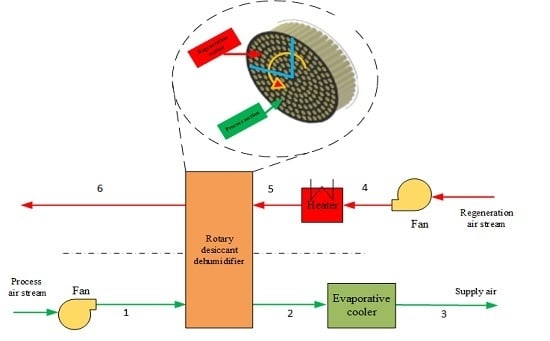
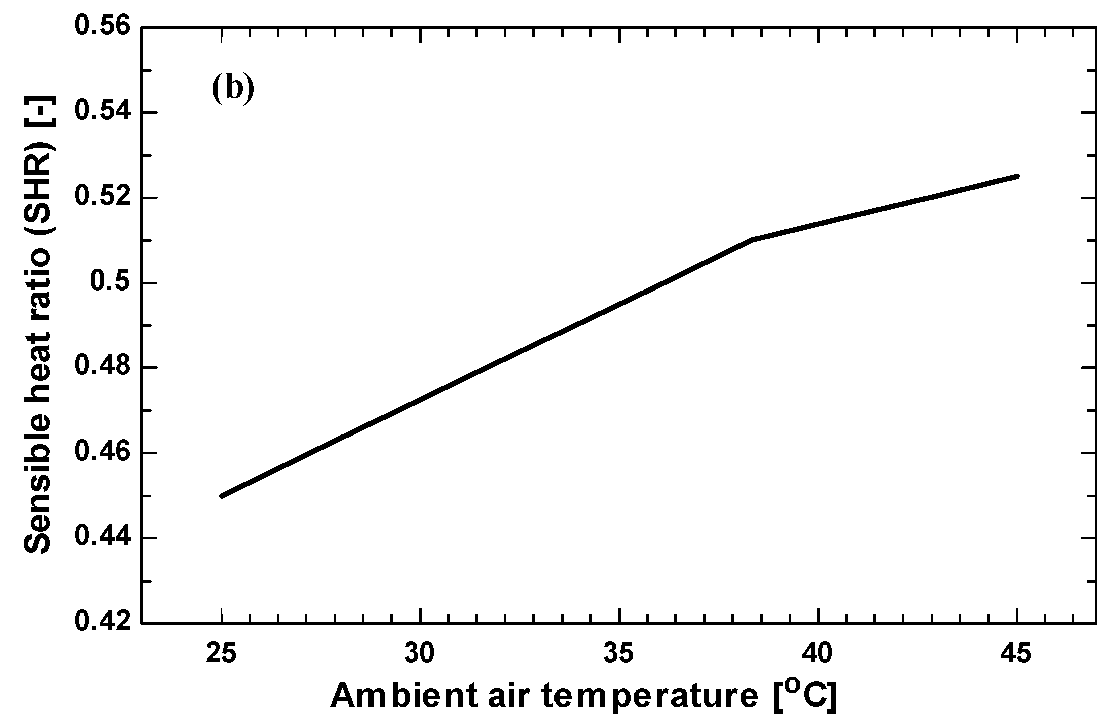
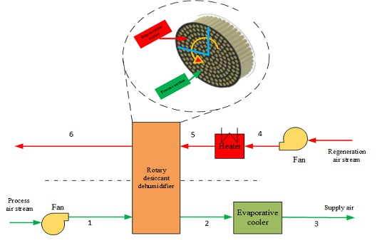
In this paper a rotary type liquid desiccant cooling system has been investigated. The purpose of the this investigation was to analyze the performance of a liquid desiccant cooling system with a rotary dehumidifier using a low cost and easily available liquid desiccant material (CaCl2) system. CaCl2 has a regeneration temperature of about 50–85 °C which makes the use of low grade thermal energy, like solar, more feasible. The proposed system has the advantage of conducting dehumidification and regeneration simultaneously. A mathematical model is developed for the proposed system to investigate its performance under different climatic, design, and operating conditions.
The present research paper has been divided into different sections. The scope of the present work and international practices are introduced in the Introduction Section 1 while Section 2 discusses the desiccant-based air conditioning system. Section 3 provides technical details about the proposed liquid desiccant system. The mathematical formulations of the problem are given in Section 4 and the results are discussed in Section 5. Finally, the findings of the study are summarized in Section 6.

2. Desiccant-Based Air Conditioning Systems

Desiccant dehumidification systems can dehumidify air without cooling it below its dew point temperature, unlike conventional air conditioning systems. These systems can remove moisture at higher temperatures, thus eliminating the need for reheating and can prove to be more energy efficient for the removal of latent heat [13]. Desiccant systems work near ambient pressure and can be scaled down to small capacity, unlike vapor absorption systems which are generally available above 35 kW cooling capacity [14]. Liquid desiccant air conditioning systems have additional advantages like high density energy storage at near ambient conditions and flexibility of component layouts [15]. On the other hand, there are some challenges like corrosion, carry over and low COP usually associated with this technology [16,17]. The major advantages of desiccant cooling systems can be summarized as:
  • Only air and water are required as working fluids. Chlorofluorocarbons are not required, thus, there is no adverse impact on the ozone layer.
  • The source of thermal energy can be diverse (i.e., solar, waste heat, natural gas). The electrical energy requirement can be less than 25% that of conventional refrigeration systems.
  • The sensible and latent loads can be controlled separately.
  • Emission of greenhouse gases (GHG) such as CO2 can be reduced significantly.
  • Since desiccant systems operate near atmospheric pressure, the maintenance and construction are simplified.
  • These systems can provide better indoor air quality.
Because of these advantages, many research efforts have been applied on the applications of desiccant cooling cycles [18,19]. The most popular desiccant cooling system is the Munters environmental control (MEC) cycle [20]. This cycle is very attractive due to the suitability of relatively low temperature heat sources like solar energy for the regeneration of the desiccant. However, there are still two shortcomings that need to be addressed. First, the supply air temperature in such systems is 4 °C higher than that in a conventional all air system, which means that a 60% greater volume of air needed to be pumped and circulated through the system. As a result, fan energy demand, which is already high in a conventional all-air system [21], would be further increased. This would compromise the energy savings effect of the system. Secondly, in hot and humid regions like Hong Kong, the effectiveness of desiccant dehumidification would be quite limited, which means that a heavier desiccant dehumidifier/wheel and/or a higher regenerating temperature are/is required to realize efficient dehumidification and cooling. The system would become bulky and the initial investment would be higher.
Since the 1950s, most of the studies related to liquid desiccant cooling have focused on direct contact between air and a liquid desiccant [22,23]. These direct liquid desiccant cooling systems have a significant drawback of desiccant carryover in the air streams. The liquid desiccant carryover in the air stream may affect indoor air quality and the health of occupants within the conditioned space. In addition, desiccant carryover can lead to higher maintenance costs and short life cycles because of equipment and ducting corrosion. The drawbacks mentioned above have limited the application of liquid desiccant cooling systems in different conditions [24]. To overcome the problem of desiccant carryover, different liquid desiccant dehumidifier configurations have been proposed [25]. One design to reduce the carryover problem is to use a low flow rate of process air in an internally cooled/heated dehumidifier [26,27]. The dehumidifier with indirect contact between air and liquid desiccant using membranes is another design which can help in eliminating the problem of desiccant carryover [28]. The rotary type liquid desiccant cooling system is yet another configuration to overcome the drawbacks of liquid desiccant cooling systems mentioned above. In rotary type liquid desiccant cooling systems a rotary wheel embedded with a porous media is used to carry a liquid desiccant.

3. Proposed Liquid Desiccant Cooling System

3.1. Rotary Liquid Desiccant Dehumidifier

The proposed liquid desiccant dehumidifier is a rotary wheel of radius R and width L. The rotor consists of a number of identical narrow slots uniformly distributed over its cross-section as shown in Figure 1.
The slots are covered with porous media impregnated with a solution of liquid desiccant. The wheel has separate sections for the flow of process air and regeneration air. One fourth of the air is used for regeneration and three fourths for the process air. These two streams of air flow in a counter arrangement. There is no carryover of liquid desiccant because it does not involve any spraying of liquid desiccant solution. The porous media used should have following characteristics:
  • The vapor diffusion resistance should be low to increase the moisture transfer process from air to desiccant.
  • The modulus of elasticity should be high to avoid blockages and flow disturbances in the flow channels.
  • The liquid penetration pressure should be high to avoid any leakage of desiccant into the air.

3.2. Liquid Desiccant Material

Different liquid desiccant materials which differ in cost and thermodynamic properties and can be used in liquid desiccant cooling systems are commercially available. Magnesium chloride (MgCl2), lithium chloride (LiCl), calcium chloride (CaCl2) and triethylene glycol (TEG) are the most used liquid desiccants. Composites of two or more desiccants can also be prepared to achieve the desired cost and thermodynamic property objectives. MgCl2 is an economical liquid desiccant but under some operating conditions it can lead to crystallization. The crystallization of liquid desiccants should be avoided because it leads to following disadvantages [29]:
  • It reduces the surface area for transfer of heat and mass between air and desiccant.
  • It disturbs the flow of air by blocking the flow channels.
  • It can cause fouling.
LiCl is an expensive desiccant as compared to MgCl2 and CaCl2 [29]. Therefore, CaCl2 has been selected for the present study due to its absence of crystallization, lower cost, and ease of availability.

3.3. System Description

The schematic of the proposed rotary liquid desiccant cooling system is shown in Figure 1. The system consists of two air streams, that is, the process and the regeneration air streams. The rotary liquid desiccant dehumidifier is the core component of the proposed system, being responsible for the removal of latent load. The dehumidifier is divided into two sections as shown in Figure 1. In the dehumidifying section, the process air is dehumidified by removing the moisture (1–2). In the regeneration section, the air is heated to the specified temperature depending upon the liquid desiccant used (4–5). The hot air then passes through the regeneration section of the dehumidifier to desorb the absorbed moisture (5–6), and concentrate the desiccant for reuse in the dehumidifier. The dehumidified air leaving the dehumidifier in the process section is cooled down to the desired supply temperature by the evaporative cooler (2–3).

4. Mathematical Formulation

4.1. Rotary Liquid Desiccant Dehumidifier

For modeling purposes, one slot is divided into N number of nodes (i = 1, 2, 3…, N) as illustrated in Figure 2. One-dimensional mass and energy balance equations are developed for the air stream and desiccant surface, to determine the outlet conditions of air at state point 2. For modeling purposes, the following assumptions have been made:
  • Flow variations exist only in the axial direction.
  • The air is uniformly distributed across the rotary dehumidifier.
  • The axial heat conduction and mass diffusion are neglected.
  • No carryover of the desiccant solution.
  • Constant thermodynamic properties of air, water vapor and desiccant.
  • There is no leakage between the two streams of air.
  • All ducts are adiabatic and impermeable.
  • All channels are made of same material and of same configuration.
  • The desiccant is distributed uniformly along the channel.
The process air is in direct contact with the desiccant surface. Water vapor is absorbed by the desiccant from the humid process air because of the higher partial pressure of water vapor in air as compared to the surface of the desiccant. The released vaporization heat results in an increase in desiccant temperature, which raises the desiccant surface vapor pressure and causes a decrease in the dehumidification process.
Four governing equations for two different control volumes, one for the moist air and other for the desiccant material layer are derived using fundamental laws of mass and heat transfer. The difference of moisture contents acts as the driving force for mass transfer coefficient k. The mass conservation equation for a control volume of air stream can be written as:
( ω a , i ω a , i 1 ) Δ t = u ( ω a , i 1 ω a , i ) Δ x + k A h A c ρ a L ( ω s , i ω a , i )
Energy balance for air stream is given as:
C p a ( T a , i T a , i 1 ) Δ t = C p a u ( T a , i 1 T a , i ) Δ x + h A c A h ρ a L ( T s , i T a , i ) + C p v k A c A h ρ a L ( ω s , i ω a . i ) ( T s , i T a , i )
Similarly, mass and energy balance for desiccant surface are represented in Equations (3) and (4), respectively:
( ω s , i ω s , i 1 Δ t ) + Δ w Δ t = k A h ρ d A c L ( ω s , i ω a , i )
( T s , i T s , i 1 Δ t ) = h A c C p d A h ρ d L ( T a , i T s , i ) + k A c C p d A h ρ d L ( ω a , i ω s , i ) h f g + C p v A c C p v A h ρ d L ( ω a , i ω s , i ) ( T a , i T s , i )
The saturated humidity ratio of the air can be written in term of water vapor pressure as:
ω s i = 0.622 P v i 1.0133 × 10 5 P v i
The partial vapor pressure on the surface of CaCl2 solution is calculated using the correlations introduced by Gad et al. [30].
ln ( P v ) = ( a o + a 1 X ) ( b o + b 1 X ) T s + C
where:
a 0 = 10.0624 a 1 = 4.4674 b 0 = 739.828 b 1 = 1450.96 C = 111.96 }  when  T s = 10 65   ; X = 0.2 0.5   ( kg desiccant kg solution )
a 0 = 19.786 a 1 = 1.2151 b 0 = 4758.1735 b 1 = 1492.5857 C = 273 }  when  T s = 60 100   ; X = 0.2 0.5   ( kg desiccant kg solution )
The continuity and momentum equations can be used to calculate the profile for air stream velocity as:
m ˙ a = 2 0 r ρ a u d r
u = p x R 2 4 μ a [ 1 ( r R ) 2 ]
The relationships used to calculate convective heat and mass transfer coefficients are listed in Table 1. The above governing equations are subject to the initial and boundary conditions which are given in Table 2.

4.2. Evaporative Cooler

In the process air stream, after the desiccant dehumidifier, an evaporative cooler is used. The particular type of evaporative cooler in this case consists of a rigid, corrugated material, which forms a wetted surface. The air passes through this corrugated material and water enters from the top of it and falls by gravity. The evaporative coolers are usually rated according to their saturation effectiveness, which is defined by the following equation:
ε e v = T d b , 2 T d b , 3 T d b , 2 T w b , 2
where, subscripts 2 and 3 are referred to the inlet and outlet of the evaporative cooler as shown in Figure 1.

4.3. Heating System

It is assumed that the effectiveness and thermal efficiency (ηthermal) of the heater is constant, 0.85% and 95% respectively. Equations (12) and (13) are used to calculate the rate of thermal energy input in the heating system (Ethermal).
Q thermal = m ˙ r C p ( T 5 T 6 )
E thermal = Q thermal η thermal
where subscripts 5 and 6 are referred to the air entering and leaving the heater, respectively as shown in Figure 1.

5. Results and Discussion

In the present work, six performance parameters are used to analyze the performance of proposed rotary liquid desiccant cooling system. These parameters are as follows:
The rate of moisture removal from the process air by the liquid desiccant cooling system is defined as moisture removal rate (Mr):
M r = m ˙ p ( ω 1 ω 2 )
The amount of latent and sensible load removed by the liquid desiccant cooling system is represented by sensible heat ratio (SHR):
SHR = Q sensible Q sensible + Q latent
where Qsensible and Qlatent are the sensible and latent load removal rate from the conditioned space, respectively.
The overall cooling provided by the desiccant system is defined as cooling capacity (CC). The difference of enthalpy between outdoor and supply air is used to represent overall CC because it includes both sensible and latent loads:
Cooling capacity  ( CC ) = m ˙ p ( H 1 H 3 )
The overall performance of the system is represented by coefficient of performance (COP):
COP = CC E thermal + ( E cool + E pumping ) β
where, β equivalent conversion coefficient of electric power and thermal energy and its value is taken as 0.3.
The ratio between the CC and electrical energy consumption is given by electrical coefficient of performance (ECOP) while ratio between CC to consumption of thermal energy is represented by thermal coefficient of performance (TCOP):
ECOP = CC E cool + E pumping
TCOP = CC E thermal
The mass and energy balances for the liquid desiccant cooling system needs to be checked to ensure that the model conserves both energy and mass.
The effects of different key parameters on the performance of the proposed rotary liquid desiccant cooling system are discussed in this section. The parameters considered are effectiveness of evaporative cooler, temperature and humidity ratio of ambient air, ratio of mass flow rate, and regeneration temperature. The base values and ranges for each parameter studied in this paper are presented in Table 3. These climatic parameters have been obtained from the long-term meteorological data measured at the Research Institute of the King Fahd University of Petroleum and Minerals, Dhahran, Saudi Arabia. Only one parameter is varied in each case, keeping all other parameters constant at the reference values.
Although, the effectiveness of the evaporative cooler (εev) has no effect on SHR and MRR because these parameters are controlled by the rotary desiccant dehumidifier, it has a significant effect on the electrical and thermal energy required for the liquid desiccant cooling system. In addition, εev has strong impact on the capacity of the cooling equipment, and hence the system’s COP. Table 4 shows the effect of εev on the performance of the system. It is observed that the CC, COP, TCOP, and ECOP increase by 36%, 42%, 36% and 37%, respectively, when εev increases from 0.35 to 0.9. It is clear that installing an evaporative cooler with high effectiveness, results in considerable savings in the operating and capital costs. Furthermore, the payback period of the system is expected to be shorter. Therefore, an evaporative cooler with high effectiveness is strongly recommended to control the sensible load in liquid desiccant cooling systems.
It is worth mentioning that an efficient control system should be installed for the cooling system used in the liquid desiccant cooling cycle. This is due to the fact that sometimes it is more beneficial to bypass the air flowing around the cooling system. For example, if the temperature of the air leaving the dehumidifier is lower than the supply air temperature, the evaporative cooler makes the temperature much lower than the supply demand temperature and reheating will be required to achieve comfort conditions. This cooling and reheating will cause a decrease in performance because of the corresponding increase in the energy consumption. Therefore, the operation of an evaporative cooler should be efficiently controlled by detecting the exit temperature from the dehumidifier at state point 2.
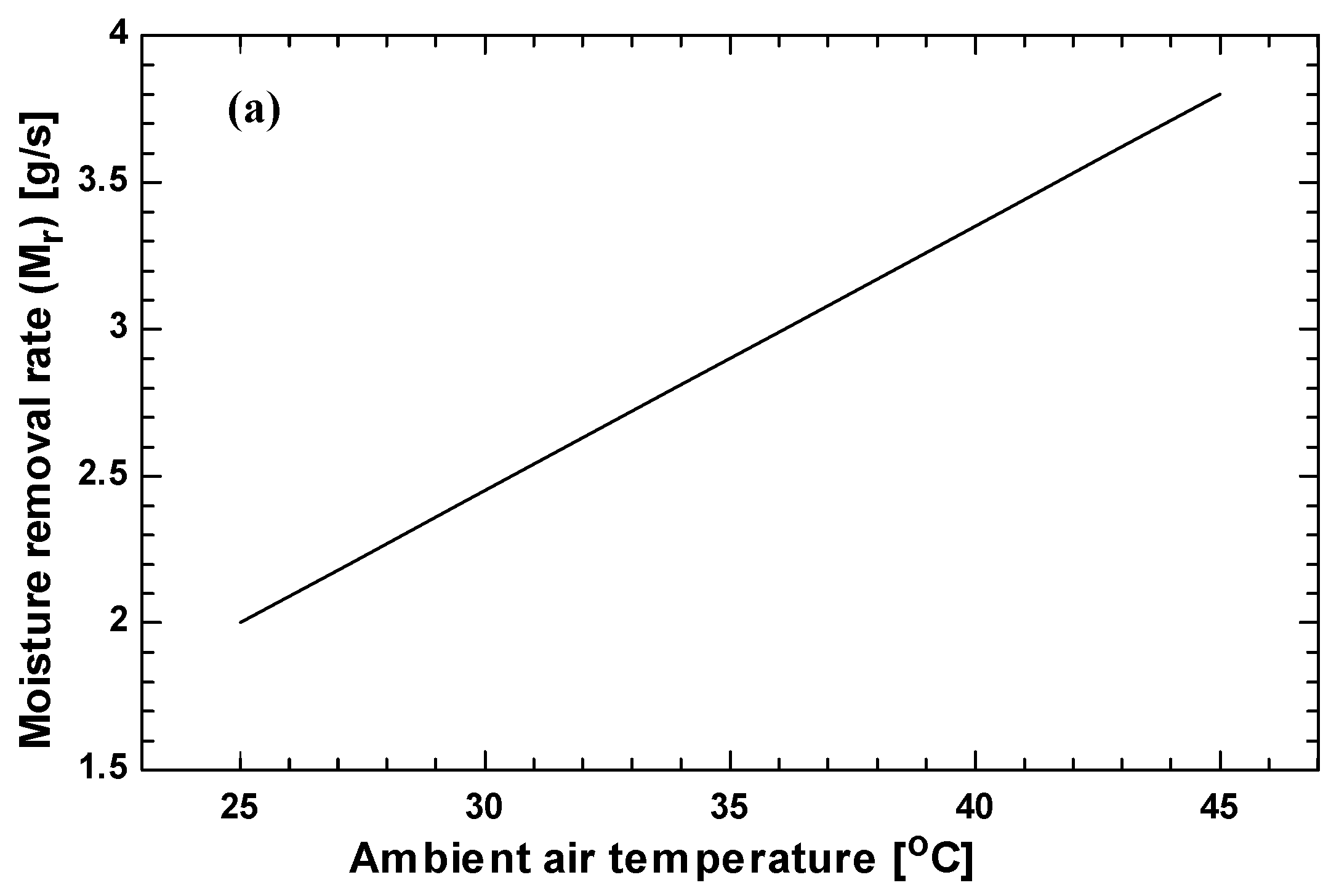
The increase of ambient air temperature causes an increase in dehumidification and cooling loads because of an increase in the potential of mass and heat transfer. In order to remove the total latent load of the conditioned space, a humidity ratio of about 10 g/kg is expected to achieve the goal depending on the indoor and outdoor ambient conditions. The proposed rotary liquid desiccant cooling system may not be able to meet latent load of the building with the reference parameters when the ambient air condition exceeds a certain temperature and humidity. Therefore, the system should be equipped with an efficient control system in order to have a better control of supply conditions according to outdoor and indoor conditions. 
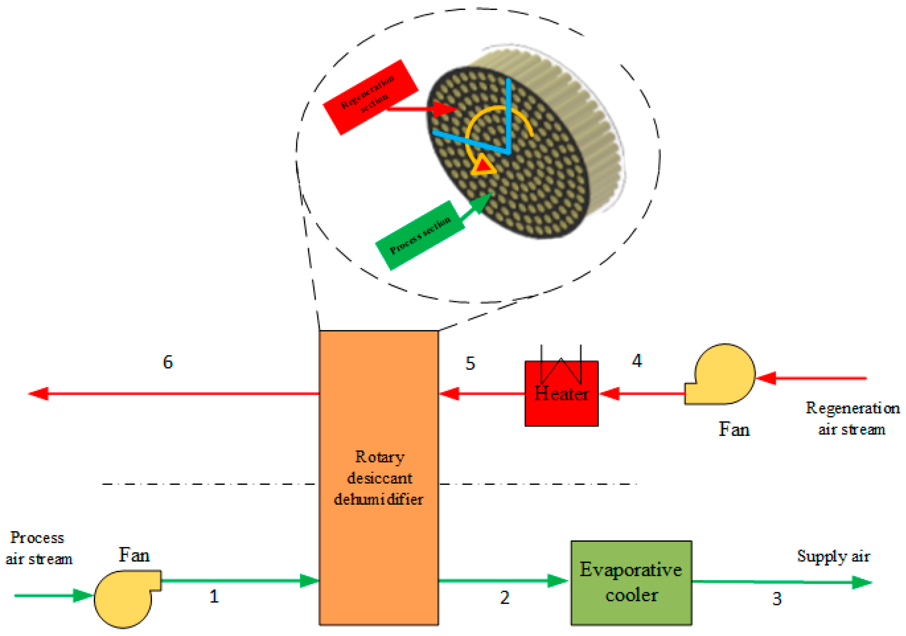
Figure 3a shows that the moisture removal rate increases linearly with ambient temperature due to the increase in potential for mass transfer. However, the sensible heat ratio (SHR) also increases with the increase in ambient air temperature, as shown in Figure 3b.
The temperature of air at the exit of dehumidifier (state point 2) increases with ambient air temperature. This increase in temperature difference causes an increase in the enthalpy difference of the air across the rotary dehumidifier. This explains the increase that occurs in the cooling capacity of the system, as shown in Table 5. The achieved improvement in the system performance parameters (CC, COP, ECOP, TCOP) is due to the fact that at higher ambient temperature, the amount of heat and mass transfer from the air to the desiccant increases. This enhancement of heat and mass transfer also tends to increase the amount of heat released from the air to the desiccant during the absorption process. Consequently, the thermal energy required to heat the regeneration air prior to entering the regeneration section of the rotary dehumidifier is reduced with ambient temperature. This leads to the improvement of the system performance parameters CC, COP, ECOP and TCOP. These results show that the proposed rotary liquid desiccant cooling system performs more efficiently in hot and humid climatic conditions.
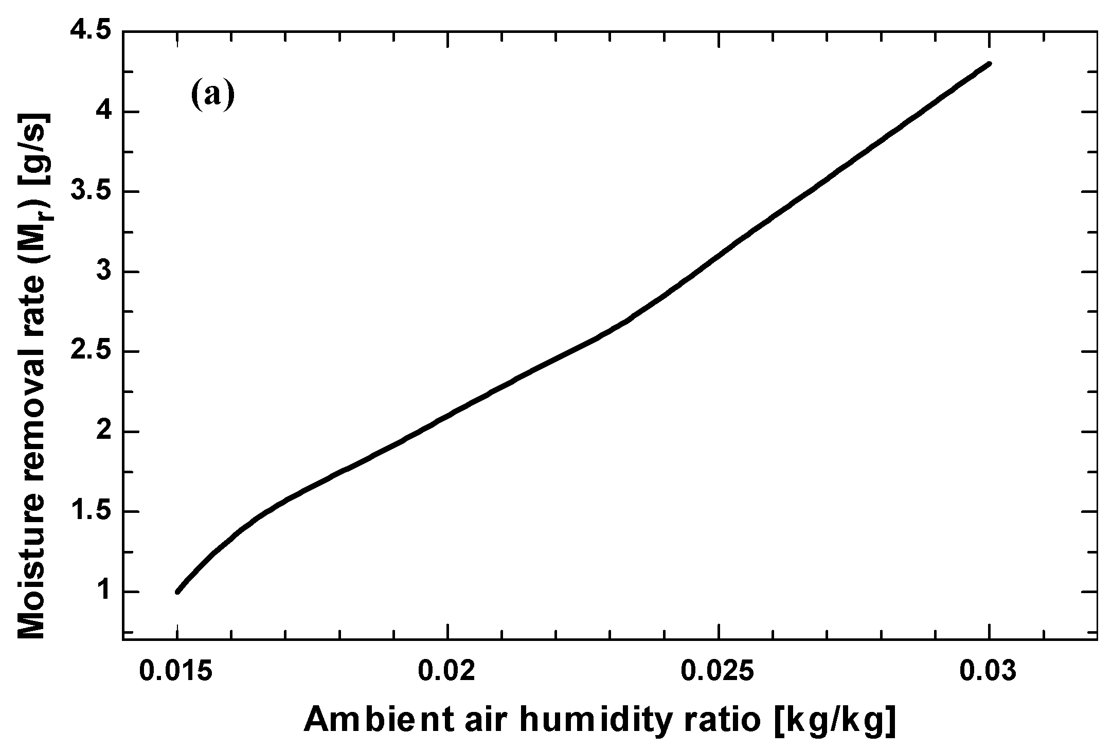
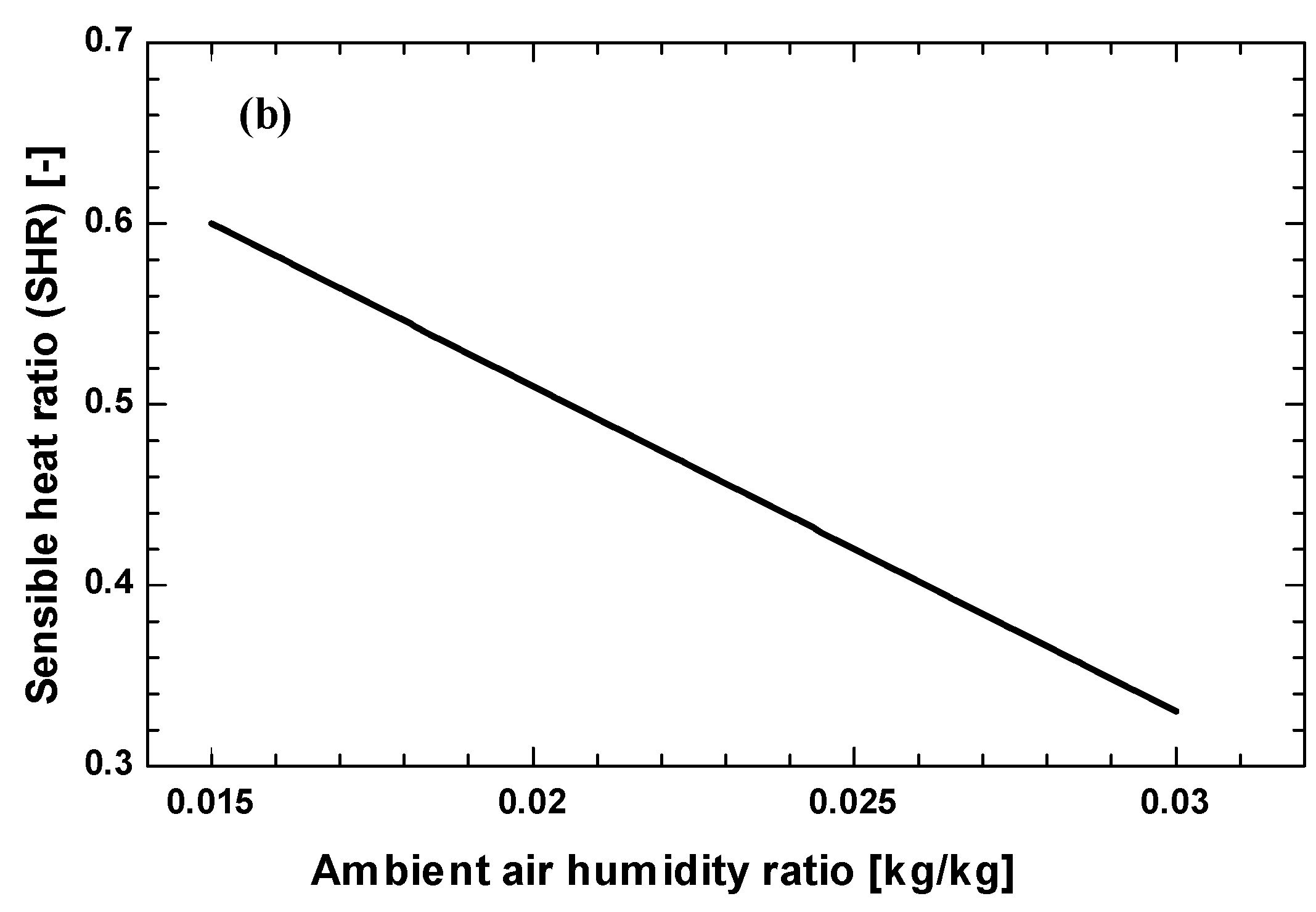
The increase in humidity ratio of the ambient air results in an increased potential for mass transfer. In turn, this increase in mass transfer enhances the rate of moisture removal from the process air by the desiccant. Figure 4 show that the moisture removal rate increases and sensible heat ratio decreases due to the increase in mass transfer potential. In fact, increasing the air inlet humidity ratio causes an increase in the driving force and hence increases the mass transfer potential within the dehumidifier. The partial vapor pressure is the governing factor for the mass transfer between process air and desiccant surface. As the inlet air humidity ratio increases, the partial pressure of water vapor in the air also increases. This enhances the difference between the partial vapor pressure of the inlet air stream and the desiccant surface which ultimately tend to increase the moisture absorbing capacity of the desiccant.
The effect of ambient humidity ratio on the performance of the system is shown in Table 6. As discussed previously, the higher the ambient air humidity, the higher the CC of the system and the lower the thermal energy demand for the system. Therefore, the COP, ECOP and TCOP increase with increasing ambient air humidity ratio, as shown in Table 6.
The air flow rate is one of the important parameters which have a strong effect on the performance of liquid desiccant cooling systems. There is no common optimum value of air flow rates that is applicable to different systems. Factors like heat and mass transfer coefficients should be considered to define the optimal value of flow rate because these factors may differ for different outdoor conditions and from system to system. The influence of the ratio between regeneration and process air flow rates on the system performance is shown in Figure 5. In this case the process air flow rate value is fixed to the base value while the mass flow rate of regeneration air is varied. The COP and TCOP decreased by 40% and 42% as the ratio of the mass flow rate increased from 0.3 to 1, respectively. This may be explained as follows: when the regeneration air flow rate increases with process air flowing at a constant rate the input energy for regeneration tends to increase which in turn decreases the system performance. Consequently, more thermal energy is consumed to condition the regeneration air to the specified temperature before entering the regeneration portion. The CC and ECOP are not affected significantly by changing mass flow rate of regeneration air due to constant flow rate of process air stream.
The regeneration temperature is an important parameter for liquid desiccant cooling systems because it affects the performance of the overall system significantly. The input thermal energy increases with the increase in regeneration temperature which decreases both the thermal and overall COP of the system as shown in Figure 6. Although a higher regeneration temperature value makes the moisture removal process faster, at the same time this higher temperature value tends to dry up the desiccant wheel before the completion of the regeneration period. Hence, some added energy is wasted and is not utilized during the absorption period for moisture removal. Secondly, the higher regeneration temperature value increases the input energy which decreases the COP of the cycle. A low regeneration temperature enhances the potential of these systems for use in solar applications. The COP and TCOP of the system decreased from 0.91 to 0.52 and 3.4 to 1, respectively, when the regeneration temperature increased from 50 to 85 °C.
It is observed from the above results that the system performance is largely affected by the variations of inlet air humidity ratio, mass flow rate of regeneration air, and regeneration temperature. System performance improvements are expected at lower regeneration temperatures and regeneration air mass flow rates as both of these have a direct effect on the required input thermal energy.

6. Conclusions

In this study, the performance of a liquid desiccant cooling system has been investigated using a rotary dehumidifier under various operating and climatic conditions. The proposed system is found to be technically suitable and energy efficient for hot and humid climatic conditions. It has been found that the effective control of dehumidification capacity can be achieved by regulating the temperature and humidity of the air entering the dehumidifier. The system performance significantly improved with the effectiveness of the evaporative cooler. Also, decreasing the ratio of mass flow rates and regeneration temperature was beneficial for the performance of the system. The use of low grade energy sources such as solar and waste heat makes the proposed liquid desiccant cooling system more energy efficient and environmentally friendly. The sensible heat ratio changed from 0.45 to 0.53 as the ambient air temperature increased from 25 to 45 °C because of a significant increase in heat transfer potential compared to mass transfer. For certain operating conditions, the operating costs may be reduced significantly, but this can be accompanied by a higher capital cost. Therefore, the optimal values for all parameters should be selected considering both operating as well as capital expenses.

Acknowledgments

The authors would like to acknowledge the support provided by King Fahd University of Petroleum & Minerals (KFUPM). Aref Lashin extends his appreciation to the Deanship of Scientific Research at King Saud University (Saudi Arabia) for funding the work through the international research group project No. IRG14-36.

Author Contributions

This paper is the outcome of the full collaboration of all the authors. All authors have participated in preparing the research from the beginning to the end, such as establishing research design, method and analysis. All authors discussed and finalized the analysis results to prepare manuscript according to the progress of research.

Conflicts of Interest

The authors declare no conflict of interest.

Nomenclatures

Achannel area (m2)
Bwidth of flow channel (m)
Cpspecific heat (kJ/kg·°C)
COPcoefficient of performance (-)
CCcooling capacity (kW)
Dhhydraulic diameter of the flow channel (m)
Erate of energy consumption (kW)
ECOPelectrical coefficient of performance (-)
hheat transfer coefficient (W/m2·°C)
Hspecific enthalpy (kJ/kg)
H*operating condition factor
hfglatent heat of vaporization (kJ/kg)
kmass transfer coefficient (kg/m2·s)
kathermal conductivity (W/m·°C)
Llength of flow channel (m)
Mrmoisture removal capacity (kg/s)
m ˙ air mass flux (kg/m2·s)
Nnumber of cells in each slot (-)
Peperimeter of the flow channel (m)
Ppressure (kPa)
Qrate of heat transfer (kW)
SHRsensible heat ratio (-)
Ttemperature (°C)
TCOPthermal coefficient of performance (-)
ttime (s)
uface velocity (m/s)
VHair specific volume (m3/kg)
wdesiccant moisture content (kg/kg)
Greek Letters
αaspect ratio (-)
β equivalent conversion coefficient (-)
μdynamic viscosity of the air (kg/m·s)
ρdensity (kg/m3)
ωhumidity ratio (g/kg)
ε effectiveness (-)
Subscripts
aair
ambambient
ccross sectional
ddesiccant material
dbdry bulb
dpdew point
evevaporative cooler
fwall material
hinternal surface
pprocess
rregeneration
sdesiccant surface
vwater vapor
wliquid water
wbwet bulb

References

  1. Perez-Lombard, L.; Ortiz, J.; Pout, C. A review on buildings energy consumption information. Energy Build. 2008, 40, 394–398. [Google Scholar] [CrossRef]
  2. Qi, R.; Lu, L.; Yang, H. Investigation on air-conditioning load profile and energy consumption of desiccant cooling system for commercial buildings in Hong Kong. Energy Build. 2012, 49, 509–518. [Google Scholar] [CrossRef]
  3. Fong, J.; Zaid, A. Modelling to predict future energy performance of solar thermal cooling systems for building applications in the North East of England. Appl. Thermal Eng. 2013, 57, 81–89. [Google Scholar] [CrossRef]
  4. ASHRAE Handbook; HVAC systems and equipment, Inc.: Atlanta, GA, USA, 2008.
  5. Rafique, M.M.; Rehman, S.; Lashin, A.; Al Arifi, N. Analysis of a solar cooling system for climatic conditions of five different cities of Saudi Arabia. Energies 2016, 9, 75. [Google Scholar] [CrossRef]
  6. Rafique, M.M.; Gandhidasan, P.; Rehman, S.; Al-Hadhrami, L.M. A review on desiccant based evaporative cooling systems. Renew. Sustain. Energy Rev. 2015, 45, 145–159. [Google Scholar] [CrossRef]
  7. Mazzei, P.; Minichiello, F.; Palma, D. HVAC dehumidification systems for thermal comfort: A critical review. Appl. Thermal Eng. 2005, 25, 677–707. [Google Scholar] [CrossRef]
  8. Fong, K.F.; Lee, C.K.; Chow, T.T.; Fong, A.M.L. Investigation on solar hybrid desiccant cooling system for commercial premises with high latent cooling load in subtropical Hong Kong. Appl. Thermal Eng. 2011, 31, 3393–3401. [Google Scholar] [CrossRef]
  9. Jain, S.; Sagun, T.; Das, R.S. Experimental performance of a liquid desiccant dehumidification system under tropical climates. Energy Convers. Manag. 2011, 52, 2461–2466. [Google Scholar] [CrossRef]
  10. Rafique, M.M.; Gandhidasan, P.; Al-Hadhrami, M.L.; Rehman, S. Energy, exergy and anergy analysis of a solar desiccant cooling system. J. Clean Energy Technol. 2016, 4, 78–83. [Google Scholar] [CrossRef]
  11. ASHRAE. ASHRAE Handbook; HVAC systems and equipment, American Society of Heating, Refrigerating and Air-Conditioning Engineers, Inc.: Atlanta, GA, USA, 2012. [Google Scholar]
  12. Rafique, M.M. A statistical analysis of desiccant dehumidifier for air conditioning application. Int. J. Hybrid Inf. Technol. 2015, 8, 245–256. [Google Scholar] [CrossRef]
  13. Grossman, G.; Johannsen, A. Solar cooling and air conditioning. Prog. Energy Combust. Sci. 1981, 7, 185–228. [Google Scholar] [CrossRef]
  14. Guidelines for Solar Cooling Feasibility Studies and Analysis of the Feasibility Studies. Altener Project #4.1030/Z/02–121/20, 2005.
  15. Kessling, W.; Laevemann, E.; Kapfhammer, C. Energy storage for desiccant cooling systems component development. Solar Energy 1998, 64, 209–221. [Google Scholar] [CrossRef]
  16. Conde-Petit, M. Liquid desiccant-based air-conditioning systems—LDACS. In Proceedings of the 1st European Conference on Poly-generation, Tarragona, Spain, 16–17 October 2007.
  17. Waugaman, D.G.; Kini, A.; Kettleborough, C.F. A review of desiccant cooling systems. ASME J. Energy Resour. Technol. 1993, 115, 1–8. [Google Scholar] [CrossRef]
  18. Abdel-Salam, A.H.; Simonson, C.J. State-of-the-art in liquid desiccant air conditioning equipment and systems. Renew. Sustain. Energy Rev. 2016, 58, 1152–1183. [Google Scholar] [CrossRef]
  19. Warren, M.L.; Wahlig, M. Analysis and comparison of active solar desiccant and absorption cooling systems: Part I—Model description. ASME J. Solar Energy Eng. 1991, 113, 25–30. [Google Scholar] [CrossRef]
  20. Brodrick, J.R.; Westphalen, D. Uncovering auxiliary energy use. ASHRAE J. 2001, 43, 58–61. [Google Scholar]
  21. Fumo, N.; Goswami, D.Y. Study of an aqueous lithium chloride desiccant system: Air dehumidification and desiccant regeneration. Solar Energy 2002, 72, 351–361. [Google Scholar] [CrossRef]
  22. Koronaki, I.P.; Christodoulaki, R.I.; Papaefthimiou, V.D.; Rogdakis, E.D. Thermodynamic analysis of a counter flow adiabatic dehumidifier with different liquid desiccant materials. Appl. Thermal Eng. 2013, 50, 361–373. [Google Scholar] [CrossRef]
  23. Bergero, S.; Chiari, A. On the performances of a hybrid air-conditioning system in different climatic conditions. Energy 2011, 36, 5261–5273. [Google Scholar] [CrossRef]
  24. Sullivan, C. Liquid desiccant dehumidification for challenging environments. Eng. Syst. 2011, 28, 38–45. [Google Scholar]
  25. Abdel-Salam, A.H.; McNevin, C.; Crofoot, L.; Harrison, S.J.; Simonson, C.J. A field study of a liquid desiccant air conditioning system: Quasi-steady and transient performance. ASME J. Sol. Energy Eng. 2016, 138. [Google Scholar] [CrossRef]
  26. Khan, A.Y. Cooling and dehumidification performance analysis of internally-cooled liquid desiccant absorbers. Appl. Thermal Eng. 1998, 18, 265–281. [Google Scholar] [CrossRef]
  27. Abdel-Salam, A.H.; Simonson, C.J. Capacity matching in heat-pump membrane liquid desiccant air conditioning system. Int. J. Refrig. 2014, 48, 166–177. [Google Scholar] [CrossRef]
  28. Afshin, M.; Simonson, C.J.; Besant, R.W. Crystallization limits of LiCl-water and MgCl2-Water salt solutions as operating liquid desiccant in the RAMEE system. ASHRAE Trans. 2010, 116, 494–506. [Google Scholar]
  29. Hamed, M.; El-Sharkawy, I.I. Application of a solar desiccant/collector system for water recovery from atmospheric air. Renew. Energy 2001, 22, 541–556. [Google Scholar]
  30. Cengel, Y. Heat Transfer—A Practical Approach; WCB/McGraw-Hill: New York, NY, USA, 1998. [Google Scholar]
Figure 1. A schematic of the proposed rotary liquid desiccant cooling system.
Energies 09 00305 g001
Figure 2. Differential control volume for one channel.
Energies 09 00305 g002
Figure 3. Effect of ambient air temperature on (a) moisture removal rate (Mr); (b) sensible heat ratio (SHR).
Energies 09 00305 g003aEnergies 09 00305 g003b
Figure 4. Effect of ambient air humidity ratio on (a) moisture removal rate (Mr); (b) sensible heat ratio (SHR).
Energies 09 00305 g004aEnergies 09 00305 g004b
Figure 5. Effect of mass flow rate ratio on the system performance.
Energies 09 00305 g005
Figure 6. Effect of regeneration temperature on the system performance.
Energies 09 00305 g006
Table 1. Relationships for heat and mass transfer coefficients.
ParameterExpression
Nusselt number for fully developed flow N u , F D = 1.1791 × [ 1 + 2.7701 ( α ) 3.1901 ( α ) 2 + 1.9975 ( α ) 3 0.4966 ( α ) 4 ]
Aspect ratio α = L B
Local Nusselt number N u l o c a l = N u , F D + 0.0841 0.002907 + G z 0.6504
Graetz number G z = Re Pr P e 4 L
Reynolds number Re = ρ u D h μ
Prandtl number P r = μ C p k a
Coefficient of local heat transfer h = N u l o c a l k a D h
Local Sherwood number S h L o c a l = N u L o c a l L e 1 / 3
Lewis number L e = k C p D h
Local mass transfer coefficient k = ρ S h L o c a l D m D h
Mass diffusion coefficient D m = 2.302 × 10 5 ( P a m b P ) ( T T a m b ) 1.81
Table 2. Initial and boundary conditions.
Initial ConditionsBoundary Conditions
T a ( x , 0 ) = T p , i n T a ( 0 , t ) = T p , i n
ω a ( x , 0 ) = ω p , i n ω a ( 0 , t ) = ω p , i n
T s ( x , 0 ) = T r , i n T a ( L , t ) = T r , i n
ω s ( x , 0 ) = ω p , i n ω a ( L , t ) = ω r , i n
w ( x , 0 ) = w i n
Table 3. The range and base value of different parameters.
ParameterUnitBase ValueRange
Regeneration temperature (T5)(°C)7050–85
Ambient air temperature (T1)(°C)3525–45
Ambient air humidity ratio (ω1)(kg/kg)0.020.015–0.030
Evaporative cooler effectiveness (εev)(-)0.850.35–0.90
Process air flow rate(kg/s)0.50.3–1
Regeneration air flow rate(kg/s)0.200.1–1
Table 4. Effect of evaporative cooler effectiveness on the system performance.
Evaporative Cooler EffectivenessCC (kW)COP (-)ECOP (-)TCOP (-)
0.3517.240.4592.8730.985
0.4018.220.4853.0371.041
0.4519.200.5123.2011.097
0.5020.180.5383.3641.153
0.5521.160.5643.5271.209
0.6022.140.5903.6911.265
0.6523.130.6163.8541.321
0.7024.110.6424.0181.378
0.7525.090.6694.1811.434
0.8026.070.6954.3451.490
0.8527.100.7074.5101.521
0.9027.900.8014.6211.553
Table 5. Effect of ambient temperature on the system performance.
Ambient Temperature (°C)CC (kW)COP (-)ECOP (-)TCOP (-)
2515.600.3282.6010.567
2716.690.3592.7810.632
2917.770.3922.9620.703
3118.860.4273.1430.780
3319.940.4633.3240.865
3621.030.5013.5050.958
3822.120.5413.6871.062
4023.210.5843.8681.177
4224.300.6294.0511.306
4525.390.6774.2321.451
Table 6. Effect of ambient humidity ratio on the system performance.
Ambient Humidity Ratio (kg/kg)CC (kW)COP (-)ECOP (-)TCOP (-)
0.01515.910.3742.6510.707
0.01617.430.4102.9050.774
0.01818.960.4463.1600.842
0.02020.490.4823.4150.910
0.02122.020.5183.6700.978
0.02323.550.5543.9251.047
0.02525.080.5904.1801.115
0.02626.610.6264.4361.183
0.02828.150.6624.6911.251
0.03029.680.6984.9471.319

