
Smart Distribution Systems


1
School of Electrical Engineering and Computer Science, Washington State University, Pullman, WA 99164, USA
2
School of Mechanical and Materials Engineering, University College Dublin, Belfield, Dublin 4, Ireland
*
Author to whom correspondence should be addressed.
Energies 2016, 9(4), 297; https://doi.org/10.3390/en9040297
Submission received: 6 March 2016
/
Revised: 1 April 2016
/
Accepted: 11 April 2016
/
Published: 19 April 2016
(This article belongs to the Special Issue Electric Power Systems Research)
Abstract
:The increasing importance of system reliability and resilience is changing the way distribution systems are planned and operated. To achieve a distribution system self-healing against power outages, emerging technologies and devices, such as remote-controlled switches (RCSs) and smart meters, are being deployed. The higher level of automation is transforming traditional distribution systems into the smart distribution systems (SDSs) of the future. The availability of data and remote control capability in SDSs provides distribution operators with an opportunity to optimize system operation and control. In this paper, the development of SDSs and resulting benefits of enhanced system capabilities are discussed. A comprehensive survey is conducted on the state-of-the-art applications of RCSs and smart meters in SDSs. Specifically, a new method, called Temporal Causal Diagram (TCD), is used to incorporate outage notifications from smart meters for enhanced outage management. To fully utilize the fast operation of RCSs, the spanning tree search algorithm is used to develop service restoration strategies. Optimal placement of RCSs and the resulting enhancement of system reliability are discussed. Distribution system resilience with respect to extreme events is presented. Test cases are used to demonstrate the benefit of SDSs. Active management of distributed generators (DGs) is introduced. Future research in a smart distribution environment is proposed.
1. Introduction
Electric power distribution systems are designed to deliver power from substations to customers. Efficient delivery and reliability of service are crucial measures for distribution systems. However, extreme events, such as Superstorm Sandy [1] and derecho [2], threaten the reliable operation of distribution systems, and cost the economy billions of dollars [3], e.g., an estimated loss of $52 billion due to Superstorm Sandy [2]. Destructive hurricanes, winter storms, and other extreme weather events, resulting from global climate change, may further challenge the reliable operation of distribution systems. To minimize the impact of these events on reliable power supply, governments and utilities are making an effort toward smart distribution systems (SDSs) through grid modernization [4].
Traditionally, limited information is acquired along distribution feeders with few deployed sensors. Crews are sent to gather field data and operate devices on site [5]. The lack of remote monitoring and control capability limits distribution operators’ ability to monitor system operations and take control actions promptly in response to extreme events. It may take them hours to determine fault locations through field crews and trouble calls from affected customers.
The observability and controllability of distribution systems can be enhanced by adopting emerging intelligent devices and smart grid applications. With the ongoing smart grid development, smart meters and remote control switches (RCSs) are deployed nationwide in the U.S. According to [6], a total of 7661 RCSs have been installed by 2013. It is estimated that 65 million smart meters have been installed by 2015 [7]. These devices with bidirectional communication are accelerating the transformation to SDSs of the future [8]. In a SDS, a large amount of data, gathered by smart meters and intelligent electronics devices (IEDs), provides sufficient information to monitor system operations in nearly real time. Smart grid applications, such as advanced outage management and fault location, isolation, and service restoration (FLISR), are developed and integrated into Outage Management Systems (OMSs) and Distribution Management Systems (DMSs) [9]. These tools assist distribution operators in determining optimal system operation strategies and taking control actions promptly in response to a disturbance.
This paper is focused on the state-of-the-art applications of smart meters and RCSs in SDSs. The impact of extreme events on distribution systems is analyzed to highlight the importance of developing SDSs. With the availability of numerous smart meters, applications based on data gathered from these meters are discussed. A new method, called Temporal Causal Diagram (TCD), is presented for enhanced outage management by incorporating outage reports from smart meters. Fault isolation and service restoration are implemented to restore service to the interrupted customers. A state-of-the-art survey is conducted on service restoration techniques. Specifically, the spanning tree search algorithm, which determines service restoration strategies that restore the maximum amount of interrupted load with a minimum number of switching operations, is illustrated with examples. Methodologies for placement of RCSs to enhance service restoration capability are discussed. The enhancement of system reliability through added remote control capability is demonstrated. Distribution system resilience with respect to extreme events is discussed and demonstrated using numerical simulation results of the Pullman-Washington State University (WSU) distribution system. In addition, worldwide development of SDSs, especially in Europe, and active management of DGs are summarized.
2. Smart Distribution System Development in the U.S.
2.1. Enhanced System Reliability Utilizing Smart Grid Technologies
To quantify the reliability of a distribution system, the System Average Interruption Duration Index (SAIDI) is widely used by utilities [10]. Reliability of the U.S. electric energy distribution system during 2000–2012 is summarized in [11]. Take 2012 for instance. The average SAIDI in the U.S. is above 100 min without consideration of major events [11]. According to [12], SAIDI in South Korea in the same year is about 11 min. The enhanced reliability of South Korea distribution systems results from a high level of distribution automation through deploying smart grid technologies [13]. By 2012, South Korea has upgraded 48% of manual switches to RCSs and deployed DMSs widely in the distribution operating center [12].
As a result of the American Recovery and Reinvestment Act of 2009, the U.S. Department of Energy (DOE) in collaboration with power industries launched the Smart Grid Investment Grant (SGIG) program [6,14], which is aimed at modernizing electric power grids with advanced tools and smart grid techniques. Billions of dollars have been invested in modernization of power grids across the country. As of March 2013, 7661 RCSs through SGIG have been deployed on 6500 distribution feeders, which account for around 4% of the estimated 160,000 distribution feeders in the U.S. [6]. The projected SGIG expenditures at completion are summarized in Figure 1.
Ninety-nine smart grid demonstration projects have been funded from transmission systems to end-use customers. An estimated total of $4.05 billion and $1.96 billion have been invested in deploying Advanced Metering Infrastructures (AMIs) and automating electric distribution systems, respectively. These advanced tools and emerging smart grid technologies play an important role in improving system reliability. It is reported by the U.S. DOE that SAIDI of the smart grid demonstration systems is decreased by up to 56% [6].
2.2. Smart Distribution Systems under Extreme Events
Extreme events are a threat to reliable operation of distribution systems. According to [1], power outages caused by severe weather events account for 58% of total outages since 2002. Electric power distribution infrastructures, including substations, power lines, and utility poles, were severely damaged as a result of these extreme events. During Superstorm Sandy, 50 substations, 2100 transformers, and 4500 utility poles in the Long Island Power Authority (LIPA)’s service territory experienced damage [15]. Power recovery to 84 percent of the total interrupted customers was not achieved until six days after the occurrence of Sandy [15]. The devastating effect of extreme events was demonstrated by Hurricane Irene as well. When Irene moved up along the East Coast from South Carolina to Maine, 6.69 million customer outages were reported with an estimated damage of nearly $15.8 billion [15,16].
Distribution automation and smart grid technologies enhance the ability of a distribution system to withstand extreme events and restore power supply to interrupted customers efficiently after major outages. It is reported in [14] that Electric Power Board of Chattanooga (EPB), serving about 170,000 customers in Tennessee and Georgia, successfully improved outage responses by using RCSs. When nine tornados ripped through EPB territories in 2011, with 122 RCSs in service, damaged distribution lines were isolated remotely and power was restored to interrupted customers promptly. A total of 250 truck rolls were avoided and thousands of hours of outage time were saved. It is expected by EPB that upon the completion of the SGIG program, the power outage duration can be further lowered by more than 40 percent and system reliability can be increased, which is worth more than $35 million per year [14]. Besides deploying RCSs, utilities across the U.S. installed numerous smart meters at customers’ premises. The potential application of outage reports from smart meters was demonstrated by Philadelphia Electric Company (PECO) [6]. By leveraging smart meter outage reports for advanced outage management, PECO was able to restore electrical service to interrupted customers 2–3 days sooner than would have been in the event of Superstorm Sandy, and more than 6000 truck rolls were avoided [7].
3. Smart Metering Technology
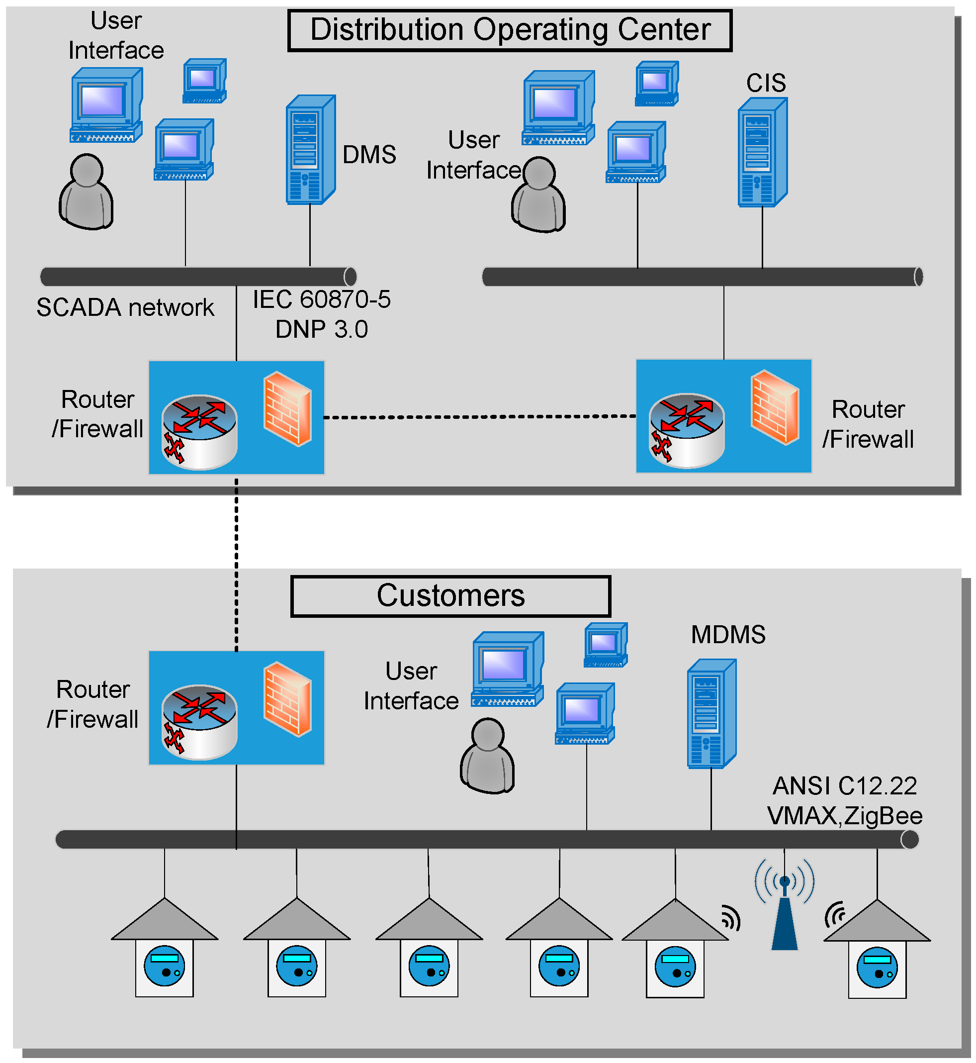
In a SDS, smart meters play an important role in acquiring data and enhancing the situational awareness of system operators. A smart meter is an electronic device with two-way communications that can automatically transmit customers’ energy consumption data as well as system operation information to the distribution operating center [17]. The available information includes the values of voltage and real and apparent power [18]. A large amount of data from smart meters provides distribution operators with near real-time monitoring of system operations. The architecture for integration of smart meters in the distribution operating center is illustrated in Figure 2. Smart meters are set up to collect data every 5 min and transmit the information via a Local Area Network (LAN) to a Meter Data Management System (MDMS) as often as 15 min or more infrequently according to the data usage [17]. Peer-to-Peer (P2P) and Zigbee technologies are widely used in a LAN [17]. To pass on the data to the central collection point in the distribution operating center, a Wide Area Network (WAN), e.g., Power Line Carrier (PLC), is adopted [17,19,20]. The data is then processed at the distribution operating center for customer billing, outage management, and other operational purposes.
By 2015, an estimated total of 65 million smart meters have been installed in the U.S. [7] and this number keeps increasing. As more smart meters with communications are deployed, concerns regarding data security and integrity arise [21,22]. To address these issues, a comprehensive set of cyber security guidelines has been published by the National Institute of Standards and Technology (NIST) [23,24]. It is required that system vendors comply with new requirements to address remote access, authentication, encryption, and privacy of metered data and customer information. Besides these guidelines, research related to cyber security of smart meters is being conducted to prevent metering infrastructures from cyber-attacks [25,26,27,28]. Issues concerning health effects of radio frequency exposure from smart meters are also raised [29]. It is reported by California Council on Science and Technology that radio frequency exposure resulting from smart meters, when installed and maintained properly, is lower than common household electronic devices, such as cell phones and microwave ovens [30]. To standardize the radio exposure from transmitters, the Federal Communications Commission (FCC) has issued Maximum Permissible Exposure (MPE) limits for field strength and power density of radio frequency electromagnetic fields [31]. All smart meters are mandated to comply with the FCC rules.
Smart meters enable near real-time data collection and remote control capability, which provide great opportunities for utilities to improve distribution system management and operations. Applications of smart meters include:
- (1)
- Automatic customer billing: compared with kilo-watt meters, which need tedious on-site meter reading work, smart meters automatically send energy consumption data to the utility. It is reported by Avista Utilities, based in Spokane, WA, that developed customer billing portals using smart meter data reveal significant benefit to utilities as well as customers. The benefit includes recording the billing history, analyzing the bill to identify ways to increase energy efficiency, and acting as online home energy advisor to outline ways to save energy [32].
- (2)
- State estimation of distribution systems: numerous data from smart meters can be used for state estimation of distribution systems [33]. Different methods, such as weighted least square (WLS) [34], Bayesian network [35], graph theory [36], and machine learning [37], are proposed for state estimation.
- (3)
- Volt/VAR management: voltage and reactive power management is essential for utilities to minimize power losses while maintaining an acceptable voltage profile along the distribution feeder under various loading conditions [38,39]. The near real-time voltage measurements from smart meters can be used as inputs for Volt/VAR controls to support decision-making, such as switch-on/off of capacitor banks and adjustment of voltage regulator tap positions.
- (4)
- Remote connect/disconnect: two-way communications of smart meters enable distribution operators to remotely connect and disconnect meters. If a customer defaults on electricity payment, a command to the smart meter can quickly cut the customer’s power supply. Connect/disconnect functions of smart meters provide distribution operators with more remote control capability to reduce dispatching field crews [14].
- (5)
- Demand response: demand response is aimed to reduce the peak load [40], which avoids utilities from purchasing electricity at a high cost and delays the construction of new power substations. According to the U.S. Federal Energy Regulatory Commission (FERC), an estimation of 41,000 MW power is reduced through existing demand response programs in 2008 [41]. Different methods for demand response are proposed based on varying electricity prices [42,43,44] or incentives [45]. These demand response programs can be implemented through smart meters to control appliances so as to change customers’ energy consumption patterns.
- (6)
- Load modeling and forecasting: accurate load modeling and forecasting is crucial for system operations and resource planning [46]. Using data from smart meters, the daily energy consumption pattern of each customer can be identified. The loading profile of each distribution transformer is determined through aggregating energy consumption from customers downstream. The temporal relationship among different load patterns can be used for load forecasting [47].
4. Enhanced Outage Management System
In a distribution system, a fault and the resulting activation of protective devices can lead to a power outage. Detection of a fault and identifying the activated protective devices to isolate the fault are key functions of an OMS. Once the faulted line section and activated protective devices are determined, field crews are dispatched to locate the fault. Fault isolation and service restoration can then be performed with remote and/or manual switches. An advanced OMS using outage reports from smart meters can help distribution operators determine the faulted line section promptly, facilitating the service restoration process.
4.1. OMS Based on Trouble Call Handling and Meter Polling
Traditionally, distribution systems have few data acquisition points beyond the substation. When a power outage occurs, distribution operators rely on trouble calls from interrupted customers to determine the outage area. Once an outage report from a customer is received, the OMS will match the phone number from the originating call to the specific customer location, and determine the distribution transformer and protective devices on the corresponding feeder. When sufficient trouble calls are collected, the OMS predicts the actuated protective device(s) and faulted line section(s). However, it may take hours to collect a sufficient number of trouble calls. This trouble call handling prolongs the identification of outage scenarios, leading to long outage durations for affected customers.
Automatic Meter Reading (AMR) technology gives another way to access customer information [48,49]. When an outage occurs, AMR meters are polled by distribution operators. Their responses are used to determine if the corresponding customers experience a power outage. An algorithm to poll AMR meters strategically is proposed in [48]. Data from AMR meters, trouble calls, and SCADA systems are put together for accurate outage management in [5]. Regarding the low quality of AMR meter data, an intelligent data filter is proposed in [49]. Generally, AMR is considered a supplement to trouble calls. Meter polling helps reduce the time to collect evidence for identification of the outage scenario, but does not significantly enhance the intelligence of an OMS. Moreover, outage management methods based on trouble call handling and AMR meter polling have limited capabilities in handling complex outage scenarios with multiple faults and protection miscoordination.
4.2. Enhanced Outage Management Based on TCD
Outage reports from smart meters provide an efficient way to identify outage areas [50]. When a smart meter experiences the loss of power, an outage report will be sent automatically to the distribution operating center. Since service can be restored to customers by automatic reclosing of protective devices after a temporary fault, distribution operators are more interested in using smart meter outage reports for permanent fault scenarios. Thus, smart meters are set to wait for a time period, in seconds, to send outage reports after experiencing the loss of power [51]. The clock embedded within smart meters records the time when outage reports are sent. The time-stamped reports from smart meters can be used for efficient and accurate outage management. In practice, a distribution system may experience multiple faults. Additionally, protection miscoordination and missing outage reports from smart meters may occur. Therefore, accurate identification of outage scenarios is a challenging task.
In the authors’ previous work [52], a multiple-hypothesis method incorporating smart meter data, is proposed to handle complex outage scenarios with multiple faults, failures of fault indicators, protection miscoordination, and missing outage reports from smart meters. Hypotheses are generated based on the hypothetical problems in an outage scenario, i.e., the number of faults, fault indicator failures, and protection miscoordination pairs. For each hypothesis, an optimization model based on linear integer programming (IP) is used to determine the most credible outage scenario. Theoretically, infinite hypotheses are supported by the same evidence. By ignoring unlikely hypotheses, such as a scenario with a large number of faults simultaneously, a finite-size set of candidate hypotheses can be obtained. However, the number of candidate hypotheses can still be large due to various combinations of multiple factors mentioned above, leading to high computational complexity in determining the most credible hypothesis.
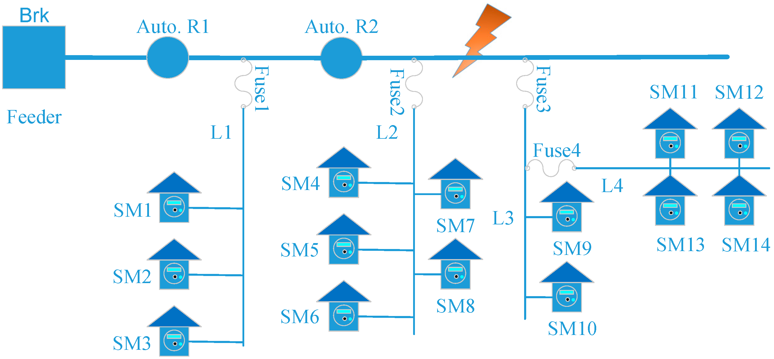
In this section, a new method for outage management, called TCD, is introduced. The distribution feeder shown in Figure 3 is used for illustration. Two automatic reclosers sectionalize the entire feeder into three segments. Four laterals supply a total of 14 customers. For each customer, a smart meter is installed. The smart meters and automatic reclosers are equipped with two-way communications. Suppose a permanent fault occurs at 9:10:13:000 a.m., as indicated by the bolt in Figure 3. Recloser R2 opens to isolate the fault. Customers served by laterals L2, L3, and L4 experience a power outage. Consequently, outage reports from smart meters SM4-SM14, and flags from reclosers R1 and R2 are transmitted to the distribution operating center. Due to failures of smart meter hardware, software, and/or firmware as well as communication problems, OMS may not receive outage reports from some smart meters that experience the loss of power.
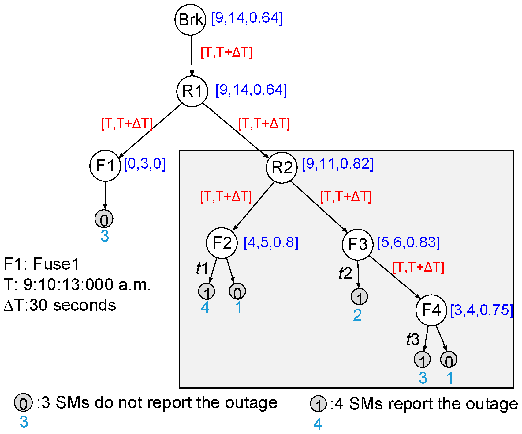
A TCD can be constructed based on the topology of the feeder as well as locations of protective devices and smart meters. The TCD for the distribution feeder in Figure 3 is shown in Figure 4. White vertices represent protective devices while smart meters are indicated by grey nodes. It can be seen that a TCD is actually a graph-theoretic tree. The vertex representing the circuit breaker is the root. The vertices representing smart meters are the leaves. Other vertices represent protective devices on the feeder. The spatial connections (upstream and downstream relationship) of these devices are represented by edges in the TCD. For example, the vertex, representing recloser R2, is directly connected with fuses F2 and F3 by an edge as recloser R2 is right upstream fuses F2 and F3. A status, i.e., 1 or 0, is assigned to each leaf. If the distribution operating center receives an outage report from a smart meter, the status of the corresponding vertex is 1. In contrast, a leaf with the status 0 indicates no outage report is received from the corresponding smart meter. Note that multiple smart meters downstream the same protective devices can be lumped into one vertex in the TCD. Therefore, one leaf in the TCD may be mapped to two or more smart meters in the distribution system. For example, the leaf connected to vertex F1 represents three smart meters that do not report an outage. The attribute t of an edge entering a leaf indicates the outage reporting time of a smart meter. Using the Escalation method [5], the number of smart meter outage notifications correlated with each protective device is determined. Three indices, i.e., , , and . are associated with each vertex that represents a protective device. Another two indices, i.e., and , are defined for each edge connecting protective devices. These indices are defined as follows:
- : number of smart meters downstream the protective device reporting a power outage;
- : total number of smart meters downstream the protective device;
- Cred.: percentage of downstream smart meters reporting an outage, ;
- : time of occurrence of a fault;
- : time window to select the smart meter notifications corresponding to an outage.
The timing attribute of the edges in the TCD establishes the temporal relationship of the outage scenario and evidence for outage management. The fault occurrence time can be obtained from the digital event recorder at substations with a resolution of half a cycle. For the given outage scenario, T is equal to 9:10:13:000 a.m. The time window, , defines the length of a time period used to filter outage reports from smart meters. Only outage reports with t falling in the range of T to T + are used in the TCD for fault scenario identification. In the example, is chosen to be 30 s. Assuming there is an outage report with time stamp t at 9:01:13:000 a.m., the outage report is abandoned as it is not in the range of 9:10:13:000 a.m. to 9:10:43:000 a.m.
The attributes , , and can be used to identify the activated protective device. Take recloser R2 as an example. Recloser R2 is correlated with nine outage reports () with a total of 11 smart meters downstream (). The credibility of R2 is . The attributes of other nodes are shown in Figure 4. It can be seen that breaker Brk and reclosers R1 and R2 are all correlated with the maximum number of outage reports. However, recloser R2 has the highest credibility of 0.82. Therefore, recloser R2 is identified as the activated protective device.
By assuming that only one fault occurs and all protective devices operate correctly, it can be concluded that recloser R2 opens to isolate the fault, and the fault location is downstream recloser R2 and upstream fuses F2 and F3. Meanwhile, with communication capabilities, the status of automatic reclosers as well as the current flowing through is transmitted to the distribution operating center. The data can help to validate the activated protective device identified from smart meter outage reports. In the example, recloser R2 reports an open status to the distribution operating center, which is consistent with the inference based on smart meter data. In addition, two missing outage reports are identified based on the fact that only nine out of 11 smart meters report an outage correctly.
Note that the TCD alone cannot identify the fault scenarios if protection miscoordination is considered. For example, if fuse F3 and recloser R2 are not coordinated, a fault downstream fuse F3 may cause recloser R2 to open. In this case, information from fault indicators will be useful. Study on integrating fault indicators with communication capabilities in the TCD is needed.
5. Distribution System Restoration
Distribution system restoration is intended to promptly restore as much load as possible in areas where electricity service is interrupted following an outage. It plays a critical role in SDSs. By operating normally open tie switches and normally closed sectionalizing switches, system topologies are altered in order to restore power supply to interrupted customers. A well-designed service restoration strategy can restore the maximum amount of load with a minimum number of switching operations [53]. Thus, the outage duration is shortened and system reliability is enhanced.
5.1. Service Restoration Procedure
Following an outage, the fault is located using the methods described in Section 4. Faulted zones are isolated by opening adjacent switches. Then the actuated breaker or recloser is reclosed to bring service back to the customers upstream the fault. The loads downstream the fault are picked up by other feeders, distributed generators, or microgrids through feeder reconfiguration. Constraints, such as limits on bus voltages and capacity of transformers, need to be evaluated. After the faulted component is repaired, switching actions will be taken to bring the distribution system back to its normal topology.
5.2. Service Restoration Algorithms
Distribution system service restoration is a multi-objective, mix-integer non-linear optimization problem with a number of constraints, including topological and operational constraints [54]. Due to its combinatorial nature, the service restoration problem is NP-hard. It is a challenge to develop an efficient algorithm to develop service restoration plans, especially for large-scale distribution systems with numerous components. Various methods have been proposed, including mathematical programming [55], heuristic search [56], expert systems [57], fuzzy logic [58], and multi-agent systems [59], to determine a final system configuration that restores the maximum amount of load.
DGs and microgrids in SDSs can serve as power resources to restore more loads when power from utilities is insufficient or unavailable. Optimal islanding strategies using DGs and micro-resources for service restoration are proposed in [60,61,62,63,64]. Methods, such as branch and bound [61], weighted graph [62], and layered directed tree model [63], are investigated to determine the islanding range.
In this section, the spanning tree search algorithm proposed in [53] is introduced. Spanning tree is a graph-theoretic term that refers to a connected graph containing all nodes in the distribution system without loops. A searching procedure is designed to identify the post-outage distribution system topology that will restore the maximum amount of load with a minimum number of switching operations while satisfying all constraints. The flow chart of the spanning tree search algorithm is shown in Figure 5.
A distribution network is formed by interconnected distribution feeders. The feeders are connected with each other through normally open tie switches. If a zone is modeled as a vertex and a switch is viewed as an edge, the distribution network can be represented as a connected graph. A spanning tree in the graph can represent the radial structure of a distribution network if all root nodes are lumped into one source node.
By operating a switch pair, i.e., opening a normally closed sectionalizing switch and closing a normally open tie switch, the original spanning tree is transformed to another one that serves as a candidate topology for the post-outage network. The spanning tree search algorithm looks for all candidate network topologies iteratively. The search process starts from the original network topology. In the first iteration, it searches for candidate network topologies that can be obtained by operating one pair of switches. Unbalanced three-phase power flow calculations are performed to check the feasibility of candidate network topologies. If there is a radial network topology that satisfies all the operational constraints, output the result; otherwise, move to the next iteration. Candidate network topologies that can be obtained by operating two, three, or more switch pairs are identified and evaluated in the second, third, and subsequent iterations, respectively. If all potential network topologies are explored and there is no configuration that satisfies all operational constraints, the partial load restoration in the out-of-service area is selected. The minimum amount of load to relieve the overload is identified for the network topology with the least severe overloading condition. Based on the previous power flow calculation results, if the lowest node voltage in the system is defined as the minimum node voltage for this network topology, the network topology with the highest minimum node voltage is the least severe overload topology.
5.3. Test Case
A 4-feeder, 1069-bus system, as shown in Figure 6, is used as the test case. The test system is based on the Taxonomy ‘‘R3-12.47-2’’ developed by Pacific Northwest National Laboratory (PNNL) [53,65]. The voltage level of the unbalanced system is 12.47 kV. The real and reactive load on each feeder is 17.467 MW and 2.362 MVar, respectively. The four feeders are interconnected through seven normally open tie switches. Four microgrids are connected to the test system, as shown in Figure 6. The real power limits for microgrids 1–4 are 5.15, 1.65, 2.5, and 1.0 MW, respectively, and the reactive power limits are 2.25, 0.95, 1.75, 0.55 MVar, respectively.
Two scenarios are simulated. The spanning tree search algorithm is used to generate service restoration strategies for both scenarios. Restoration strategies with and without microgrids are compared. The results are summarized in Table 1. In scenario 1, a fault occurs at zone Z139. Without microgrids, a partial restoration strategy will be applied, with 315.04 kVA load at feeder F-b remaining interrupted.
With the help of Microgrid 2, full restoration is achieved. In scenario 2, a fault is assumed to be located at zone Z23. With or without microgrids, all load in the outage area is successfully restored. However, by using Microgrid 1 for service restoration, only one switching operation is needed after fault isolation, while five switching operations are needed for the case without microgrids. In summary, microgrids enhance service restoration capability of a distribution system in two ways, restoring service to more load and reducing the number of switching operations.
6. Remote Control Capability in Smart Distribution Systems
With the ongoing development of SDSs, field devices with communication capabilities, such as RCSs, are installed in distribution systems. Two-way communications enable distribution operators to operate these devices remotely. As a result, system topologies can be altered quickly to minimize power losses or restore interrupted load.
6.1. Placement of Remote-Controlled Switches
Remote control capability is crucial for SDSs [66]. With more RCSs, distribution operators can perform service restoration faster. Since installation of RCSs is costly, the number of RCSs installed will be limited. On the other hand, critical switches that are most likely to be used for service restoration must be identified and upgraded. Therefore, the placement of RCSs must take into account the functional requirements and cost benefit [67]. Usually, switch placement is formulated as a constrained nonlinear mix-integer optimization problem [67,68,69,70,71,72,73,74,75]. Heuristics, such as fuzzy logic approach [68], genetic algorithm [69], and immune algorithm [70], are used to obtain a near-optimal solution with acceptable computational performance.
The RCS placement problem can be formulated for two scenarios. Most research is focused on optimal installation of RCSs in a distribution network without any switch deployed. In existing distribution systems, manual switches have already been installed. Utilities are interested in upgrading manual switches to RCSs to enhance service restoration capability. Given a limited budget, manual switches should be upgraded in such a way that the service restoration capability is maximized. A method based on weighted set cover is proposed in [76], which is intended to maximize restoration capability of an existing distribution system by upgrading a minimum number of manual switches to RCSs. The universal set of single-fault scenarios is considered. The concepts of load group and switch group are proposed to describe potential restoration schemes. With these concepts, the RCS placement is transformed into a weighted set cover problem. A greedy algorithm is then used to determine a near-optimal solution for the weighted set cover problem. Finally, the RCS placement plan is obtained by mapping the selected switch groups back to actual switches in the target distribution system.
6.2. Improve System Reliability with Remote Control Capability
System Average Interruption Frequency Index (SAIFI) and System Average Interruption Duration Index (SAIDI) are widely used by utilities for reliability assessment. SAIFI and SAIDI are defined by:
According to the 2014 Electric System Reliability Annual Reports [77], SAIFI and SAIDI only take into account sustained power outages, which last for five minutes or longer. Without remote control capability, switches need to be operated manually by field crews, which may take minutes to hours for truck rolls and on-site switching operations. Compared with manual switches, RCSs are remotely operated by distribution operators within seconds. As a result, fast fault isolation and service restoration can be achieved. System reliability is improved with reduced outage duration.
The 4-feeder distribution system in Figure 7 is used to show the benefit from adding remote control capability into distribution systems. Some assumptions are given as follows.
- (1)
- the mean time to operate a manual switch is 90 min;
- (2)
- the mean time to operate a remote-controlled switch is 1 min;
- (3)
- the permanence failure rate of all zones is 0.02 per year;
- (4)
- the mean time to repair the damaged component is 4 h.
Suppose that the four feeder breakers are remote-controlled while other switches are manual operated. Using the method in [76], 17 switches are selected for upgrade, including eight sectionalizing switches, five tie switches, and four microgrid switches. The selected switches are indicated by red color in Figure 7. The results are summarized in Table 2.
Consider the universal set of single-fault scenarios. Service restoration schemes are obtained using the spanning tree search algorithm discussed in Section 5.2. For each scenario, the outage duration of each customer is recorded. SAIDI and SAIFI are calculated and shown in Table 3. Note that a power outage lasting shorter than 5 min is considered momentary and not counted in the calculation of SAIDI and SAIFI. It can be seen that by upgrading the selected switches to RCSs, SAIDI is improved by 75.70% and SAIFI 16.05%.
7. Distribution System Resilience with Respect to Extreme Events
7.1. Approaches to Resilient Distribution Systems
Extreme events, such as major hurricanes and earthquakes, have a great impact on distribution systems, resulting in extended outages to customers. Distribution system resilience with respect to extreme events is considered by the U.S. Department of Energy (DOE) as an essential characteristic of the future SDSs [78]. According to U.S. Presidential Policy Directive 21 [79], resiliency is “the ability to prepare for and adapt to changing conditions and withstand and recover rapidly from disruptions”. For a distribution system, resiliency means the ability to avoid severe damages to the distribution infrastructure caused by extreme events and to restore interrupted loads efficiently after major outages [80]. Approaches to a resilient distribution system has been summarized into four categories in [80], i.e., construction programs, maintenance measures, smart grid techniques, and other approaches. Smart grid techniques play an essential role in resilient distribution systems. In this section, a smart grid application, that is, distribution service restoration, and its contributions to the enhancement of resilience will be discussed.
After an extreme event, electric power from utilities may not be available due to damages on transmission lines or substations serving a distribution system. DGs and microgrids connected to the distribution system become valuable resources for service restoration to critical loads. In this paper, critical loads refer to those necessary for maintaining basic societal functions, such as hospitals and street lighting.
Utilization of DGs, energy storages, electric vehicles (EVs), and microgrids for service restoration has been studied [60,61,81,82,83,84,85]. In [61], a multi-stage restoration procedure is proposed to maximize the amount of load restored by DGs. In [60], a decentralized multi-agent system (MAS) is proposed to restore interrupted loads using DGs and EVs. The potential to use microgrids to serve critical load on neighboring distribution feeders when utility power is unavailable has been shown in [81,82]. Procedures for microgrid-assisted service restorations are proposed in [83,84], along with practical considerations. Microgrids are used as fast-ramping sources to restore a regional grid after natural disasters in [85].
7.2. Test Case
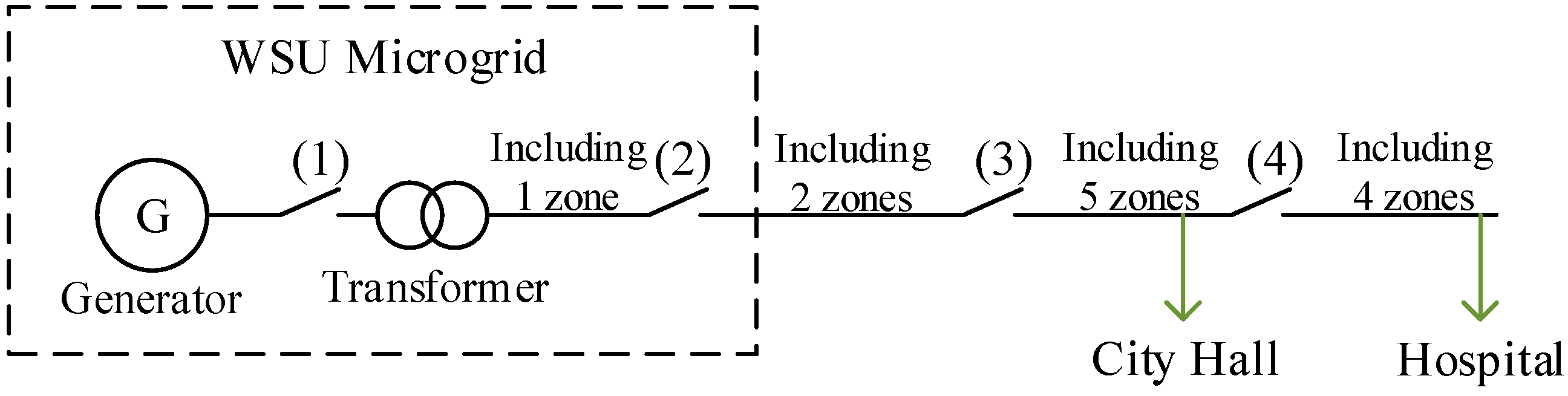
To evaluate the feasibility of using microgrids to serve critical loads in the distribution system after an extreme event, the Pullman-WSU distribution system [82,86] is used as a study case. South Pullman substation, where five Avista Utilities feeders start, and the portion of WSU microgrid served by these feeders are considered. Two critical loads are connected on the Avista Utilities feeders, i.e., the Pullman Hospital and City Hall. Three DGs, one diesel generator and two natural gas generators, with a total capacity of 3.75 MW, are installed in the WSU microgrid. Under normal operating conditions, Avista supplies power to the WSU campus and Pullman Hospital and City Hall, while the WSU generators are operating as a backup.
Suppose that an extreme event occurs at the South Pullman substation. As a result, the 5 feeders served by the substation are out of electricity service. Moreover, no power source in the Avista system is available. Therefore, the three DGs in the WSU microgrid will be used to restore service to the Hospital and City Hall. A restoration path, as shown in Figure 7, is identified [86]. All non-critical load that is connected to the restoration path through a switching device is disconnected from the restoration path by opening the corresponding switching devices. It can be seen that there are 12 zones and four normally open tie switches on the restoration path. During the restoration process, these zones will be re-energized by closing tie switches in sequence. The City Hall and Hospital will be restored in the third and fourth steps, respectively.
Unbalanced three-phase power flow calculations are performed using the GridLAB-D software tool [87] after each switching action. The output power of the WSU generators and voltages at the critical loads are given in Table 4 and Table 5, respectively. It can be seen that the generator output power does not exceed the maximum capability and the voltages at the critical loads are close to the nominal voltage during the restoration process.
8. Smart Distribution System Development around the World
To reap the benefit of SDSs, countries over the world are enhancing automation of distribution systems through deploying intelligent devices and smart grid technologies. Worldwide deployment of smart meters is expected to be around 830 million by 2020 [88]. An estimated total of 154.7 million smart meters will be deployed in Europe by 2017 [89]. In Asia, governments are making efforts to deploy smart meters for demand side management. Take South Korea as an example. South Korean government plans to install smart meters in half of the households across the country by 2016 and replace the remaining analog meters by 2020 [90]. The increased level of distribution automation helps to accommodate integration of DGs, e.g., PV modules and wind turbines, into distribution networks. In Japan, a smart grid program, named Eco-Model Cities, has been launched to develop next-generation energy and social systems using low carbon technology [90]. Real-time energy management systems for homes and buildings have been developed to integrate PV and enable demand response [90]. The potential benefits of small-scale DGs are recognized by the European energy industry [91,92]. The remaining of this section will be focused on the SDS development in Europe and active management of DGs in SDSs.
8.1. Smart Distribution System Development in Europe
In 2007, the Europe Council set up the 20:20:20 objective of reducing greenhouse gas (GHG) emissions by 20%, increasing the share of renewable energy to 20%, and making 20% improvements in energy efficiency by 2020 [90]. To meet this goal, two primary efforts are made by European countries, i.e., the deployment of smart meters and integration of DGs into distribution networks. The European Union (EU) aims to deploy around 200 million smart meters for electricity and 45 million for gas by 2020 [93]. These smart meters will help save energy consumption. For example, Greece expects 5% energy saving by deploying and making proper use of smart meters [94]. Supported by the EU Research Framework Programmes (FPs) 5–7, contributions have been made in the corresponding projects to design and validate new system architectures and advanced components towards the future European electricity networks with a high penetration level of DGs [95]. For instance, a demonstration project, Active Distribution Networks with Full Integration of Demand and Distributed Energy Resources, is aimed to explore active demand management and integration of DGs into distribution networks [90].
8.2. Active Management of DGs in Smart Distribution Systems
Renewable-based DGs, such as PV modules, and energy storage systems (ESSs) are connected to distribution systems through power electronic converters and interface protection systems (IPSs). The power electronic converters can be used to control the real and reactive power of a DG or ESS, e.g., the maximum power point tracking (MPPT) for PV [96]. The IPS protects the DG from abnormal conditions, such as faults on the distribution feeders and unintentional islanding [97]. Traditionally, the IPS monitors voltage and current at the point of common coupling (PCC) of the DG and makes decisions with local information. Such a passive scheme can cause problems. For example, the DG may continue injecting power into the distribution feeder when an unintentional islanding or external fault condition occurs [98].
By introducing communication between DGs and the distribution system control center, active management of DGs can be achieved [99]. Distribution system operators can be aware of status of DGs in the distribution system by collecting information from the DG IPSs and send control commands to DG IPSs via the communication infrastructure. Consequently, a distribution system operator can remotely disconnect DGs in the network when an abnormal condition occurs. In addition, with the communication capability, the power electronic converters of DGs can also be remotely controlled to regulate voltage or reduce the net load seen by the utilities [98].
An economic and effective solution for active IPS of DGs is proposed in [98,100]. An IPS and a communication bridge are designed. The narrow-band (NB) power line communication (PLC) technology is used to build the communication links between DGs and distribution system control center at a low cost for installation and no cost to communication providers. The effectiveness NB-PLC-based solution has been evaluated by on-site experiments [98].
9. Conclusions
The worldwide development of SDSs are introduced, particularly the progress in the U.S. and Europe. Several state-of-the-art smart grid technologies are reviewed. Smart meters and their potential applications are summarized. For enhanced outage management, TCD incorporates outage reports from smart meters to accurately identify the fault location. Service restoration strategies are determined by the spanning tree search algorithm to restore as much load as possible after an outage. A novel method for placement of RCSs to enhance distribution system restoration capability is introduced. Improved system reliability from the installation of RCSs is reported. By using microgrids to serve critical loads, the resilience of a SDS with respect to extreme events is enhanced, which is illustrated by numerical simulations of a real distribution system. Technologies for active management of DGs are presented.
It is envisioned that more smart grid technologies will be adopted by utilities in the future, enabling an efficient, economic, reliable, and resilient distribution system. As the penetration of renewable energy sources (RES), such as PV modules, continues to increase and reaches a significant level, new technologies will be needed to deal with uncertainties induced by them. Battery energy storage systems and electric vehicles will play an important role in energy management of the future SDSs. Smart buildings and smart homes will enable flexible loads to participate in demand response programs. Market mechanisms should be designed to accommodate these new participants. Interdependency between electrical systems and other critical infrastructures, such as communication, transportation, and natural gas systems, will become more important in the context of resiliency. Research on the cooperation of multiple infrastructures needs to be conducted. Finally, as various kinds of communication networks are deployed in SDSs, cyber security and privacy of customers become an important issue that needs to be addressed. Technologies for cyber-attack detection and defense should be developed and implemented to protect utilities and customers from malicious intrusions.
Acknowledgments
The research is supported by U.S. National Science Foundation Grant CNS-1329666, “CPS: Synergy: Collaborative Research: Diagnostics and Prognostics Using Temporal Causal Models for Cyber Physical Systems-A case of Smart Electric Grid” and the Office of Electricity, U.S. Department of Energy (DoE) microgrid research and development (R&D) program through Pacific Northwest National Laboratory (PNNL).
Author Contributions
The work is done by Yazhou Jiang and Yin Xu under the supervision of Chen-Ching Liu.
Conflicts of Interest
The authors declare no conflict of interest.
References
- U.S. Department of Energy. Economic Benefits of Increasing Electric Grid Resilience to Weather Outages. Available online: http://energy.gov/sites/prod/files/2013/08/f2/Grid%20Resiliency%20Report_FINAL.pdf (accessed on 30 August 2013).
- The GridWise Alliance. Improving Electric Grid Reliability and Resilience: Lessons Learned from Superstorm Sandy and Other Extreme Events. Available online: http://www.gridwise.org/documents/ImprovingElectricGridReliabilityandResilience_6_6_13webFINAL.pdf (accessed on 30 June 2013).
- U.S. Department of Energy. Smart Grid Investments Improve Grid Reliability, Resilience, and Storm Responses. Available online: http://energy.gov/oe/downloads/smart-grid-investments-improve-grid-reliability-resilience-and-storm-responses-november (accessed on 31 November 2014).
- Southern California Edison. Southern California Edison Smart Grid Strategy & Roadmap. Available online: https://www.smartgrid.gov/document/southern_california_edison_smart_grid_strategy_roadmap (accessed on 30 November 2010).
- Liu, Y.; Schulz, N.N. Knowledge-Based System for Distribution System Outage Locating Using Comprehensive Information. IEEE Trans. Power Syst. 2002, 17, 451–456. [Google Scholar]
- U.S. Department of Energy. Smart Grid Investment Grant Program. Progress Report II. Available online: https://www.smartgrid.gov/files/SGIG_progress_report_2013.pdf (accessed on 5 October 2013).
- U.S. Department of Energy. Smart Grid System Report. Available online: http://energy.gov/sites/prod/files/2014/08/f18/SmartGrid-SystemReport2014.pdf (accessed on 18 August 2014).
- Simard, G.; Uluski, R.; Larry, G. From Today’s Distribution System to Tomorrow’s Smart Distribution. Available online: http://smartgrid.ieee.org/newsletters/january-2012/from-today-s-distribution-system-to-tomorrow-s-smart-distribution (accessed on 5 January 2012).
- Teng, J.-H.; Huang, W.-H.; Luan, S.-W. Automatic and Fast Faulted Line-Section Location Method for Distribution Systems Based on Fault Indicators. IEEE Trans. Power Syst. 2014, 29, 1653–1662. [Google Scholar] [CrossRef]
- Chowdhury, A.A.; Koval, O.D. Power Distribution System Reliability: Practical Methods and Applications; John Wiley & Sons Inc.: Hoboken, NJ, USA, 2009; pp. 100–156. [Google Scholar]
- Larsen, P.; LaCommare, K.; Eto, J.; Sweeney, J. Assessing Changes in the Reliability of the U.S. Electric Power System. Available online: http://eetd.lbl.gov/sites/all/files/lbnl-188741.pdf (accessed on 3 August 2015).
- Na, B.-N. KPECO & Distribution Automation. In Presented at Washington State University, 22 July 2014. Unpublished.
- Yun, S.-Y.; Chu, C.-M.; Kwon, S.-C.; Song, I.-K.; Choi, J.-H. The Development and Empirical Evaluation of the Korean Smart Distribution Management System. Energies 2014, 7, 1332–1362. [Google Scholar] [CrossRef]
- U.S. Department of Energy. Smart Grid Investment Grant Program. Progress Report. Available online: http://energy.gov/sites/prod/files/Smart%20Grid%20Investment%20Grant%20Program%20-%20Progress%20Report%20July%202012.pdf (accessed on 5 July 2012).
- U.S. Department of Energy. Comparing the Impacts of Northeast Hurricanes on Energy Infrastructure. Available online: http://www.oe.netl.doe.gov/docs/Northeast%20Storm%20Comparison_FINAL_041513c.pdf (accessed on 30 April 2013).
- U.S. National Hurricane Center. Tropical Cyclone Report Hurricane Irene. Available online: http://www.nhc.noaa.gov/data/tcr/AL092011_Irene.pdf (accessed on 14 December 2011).
- Depuru, S.S.S.R.; Wang, L.; Devabhaktuni, V. Smart Meters for Power Grid: Challenges, Issues, Advantages and Status. Renew. Sustain. Energy Rev. 2011, 15, 2736–2742. [Google Scholar] [CrossRef]
- Itron Inc. OpenWay CENTRON Meter. Available online: https://www.itron.com/na/PublishedContent/OpenWay%20Centron%20Meter.pdf (accessed on 3 March 2016).
- Sendin, A.; Arzuaga, T.; Urrutia, I.; Berganza, I.; Fernandez, A.; Marron, L.; Llano, A.; Arzuaga, A. Adaption of Powerline Communications-Based Smart Metering Deployments to the Requirements of Smart Grids. Energies 2015, 8, 13481–13507. [Google Scholar] [CrossRef]
- Sendin, A.; Pena, I.; Angueira, P. Strategies for Power Line Communications Smart Metering Network Deployment. Energies 2014, 7, 2377–2420. [Google Scholar] [CrossRef]
- Ye, X.; Zhao, J.; Zhang, Y.; Wen, F. Quantitative Vulnerability Assessment of Cyber Security for Distribution Automation Systems. Energies 2015, 8, 5266–5286. [Google Scholar] [CrossRef]
- Cleveland, F.M. Cyber Security Issues for Advanced Metering Infrastructure. In Proceedings of the IEEE Power and Energy Society General Meeting-Conversion and Delivery of Electrical Energy in the 21st Century, Pittsburgh, PA, USA, 20–24 July 2008.
- The National Institute of Technology and Standards (NIST). Framework for Improving Critical Infrastructure Cybersecurity version 1.0. Available online: http://www.nist.gov/cyberframework/upload/cybersecurity-framework-021214.pdf (accessed on 12 February 2014).
- The National Institute of Technology and Standards (NIST). Cybersecurity for Smart Grid Systems. Available online: http://www.nist.gov/el/smartgrid/cybersg.cfm (accessed on 12 February 2014).
- Cardenas, A.A.; Berthier, R.; Bobba, R.B.; Huh, J.H.; Jetcheva, J.G.; Grochochi, D.; Sanders, W.H. A Framework for Evaluating Intrusion Detection Architectures in Advanced Metering Infrastructures. IEEE Trans. Smart Gird 2014, 5, 906–915. [Google Scholar] [CrossRef]
- Liu, N.; Chen, J.; Zhu, L.; Zhang, J.; He, Y. A Key Management Scheme for Secure Communications of Advanced Metering Infrastructure in Smart Grid. IEEE Trans. Ind. Electron. 2013, 60, 4746–4756. [Google Scholar] [CrossRef]
- Sankar, L.; Rajagopalan, S.R.; Mohajer, S.; Poor, H.V. Smart Meter Privacy: A Theoretical Framework. IEEE Trans. Smart Grid 2013, 4, 837–846. [Google Scholar] [CrossRef]
- Berthier, R.; Sanders, W.H. Specification-based Intrusion Detection for Advanced Metering Infrastructures. In Proceedings of the 17th IEEE Pacific Rim International Symposium on Dependable Computing, Pasadena, CA, USA, 12–14 December 2011.
- Electric Power Research Institute (EPRI). Radio-Frequency Exposure Levels from Smart Meters: A Case Study of One Model. Available online: http://www.epri.com/abstracts/Pages/ProductAbstract.aspx?ProductId=000000000001022270 (accessed on 2 February 2011).
- California Council on Science and Technology. Health Impacts of Radio Frequency Exposure from Smart Meters. Available online: https://ccst.us/publications/2011/2011smart-final.pdf (accessed on 5 April 2011).
- Federal Communications Commission. Radio Frequency Safety. Available online: https://www.fcc.gov/general/radio-frequency-safety-0 (accessed on 7 March 2013).
- Avista Utilities. Avista Utilities’s Pullman Smart Grid Project. Available online: https://www.smartgrid.gov/document/utility_scale_smart_meter_deployments_plans_proposals.html (accessed on 5 August 2011).
- Wang, D.; Guan, X.; Liu, T.; Gu, Y.; Shen, C.; Xu, Z. Extended Distributed State Estimation: A Detection Method against Tolerable False Data Injection Attacks in Smart Grids. Energies 2014, 7, 1517–1538. [Google Scholar] [CrossRef]
- Haughton, D.; Heydt, G. A Linear State Estimation Formulation for Smart Distribution Systems. IEEE Trans. Power Syst. 2013, 28, 1187–1195. [Google Scholar] [CrossRef]
- Hu, Y.; Kuh, A.; Yang, T.; Kavcic, A. A Belief Propagation based Power Distribution System State Estimator. IEEE Comput. Intell. Mag. 2011, 6, 36–46. [Google Scholar] [CrossRef]
- Boas Leite, J.; Sanches Mantovani, J.R. State Estimation of Distribution Networks through the Real-Time Measurements of the Smart Meters. In Proceedings of the 2013 IEEE Grenoble in PowerTech (POWERTECH), Grenoble, France, 16–20 June 2013.
- Wu, J.; He, Y.; Jenkins, N. A Robust State Estimator for Medium Voltage Distribution Networks. IEEE Trans. Power Syst. 2013, 28, 1008–1016. [Google Scholar] [CrossRef]
- Yun, S.-Y.; Hwang, P.-I.; Moon, S.-I.; Kwon, S.-C.; Song, I.-K.; Choi, J.-H. Development and Field Test of Voltage VAR Optimization in the Korean Smart Distribution Management System. Energies 2014, 7, 643–669. [Google Scholar] [CrossRef]
- Kolenc, M.; Papic, I.; Blazic, B. Minimization of Losses in Smart Grids Using Coordinated Voltage Control. Energies 2012, 5, 3768–3787. [Google Scholar] [CrossRef]
- Yang, S.; Zeng, D.; Ding, H.; Yao, J.; Wang, K.; Li, Y. Multi-Objective Demand Response Model Considering the Probabilistic Characteristic of Price Elastic Load. Energies 2014, 9. [Google Scholar] [CrossRef]
- National Action Plan for Energy Efficiency. Coordination of Energy Efficiency and Demand Response. Prepared by Charles Goldman; 2010. Available online: https://emp.lbl.gov/sites/all/files/report-lbnl-3044e.pdf (accessed on 30 January 2010). [Google Scholar]
- Federal Energy Regulatory Commission. Assessment of Demand Response & Advanced Metering Staff Report. Available online: http://www.ferc.gov/legal/staff-reports/demand-response.pdf (accessed on 17 August 2006).
- Severin, B.; Michael, J.; Arthur, R. Dynamic Pricing, Advanced Metering and Demand Response in Electricity Markets. Available online: http://sites.energetics.com/MADRI/toolbox/pdfs/vision/dynamic_pricing.pdf (accessed on 25 October 2002).
- Kang, C.; Jia, W. Transition of Tariff Structure and Distribution Pricing in China. In Proceedings of the IEEE Power and Energy Society General Meeting, San Diego, CA, USA, 24–29 July 2011.
- Cappers, P.; Goldman, C.; Kathan, D. Demand Response in U.S. Electricity Markets: Empirical Evidence. Energy 2010, 35, 1526–1535. [Google Scholar] [CrossRef]
- Gajowniczek, K.; Zabkowski, T. Data Mining Techniques for Detecting Household Characteristics Based on Smart Meter Data. Energies 2015, 8, 7407–7427. [Google Scholar] [CrossRef]
- Quilumba, F.; Lee, W.-J.; Huang, H.; Yang, D.; Szabados, R. Using Smart Meter Data to Improve the Accuracy of Intraday Load Forecasting Considering Customer Behavior Similarities. IEEE Trans. Smart Grid 2015, 6, 911–918. [Google Scholar] [CrossRef]
- Fischer, R.A.; Laakonen, A.S.; Schulz, N.N. A General Polling Algorithm Using a Wireless AMR System for Restoration Confirmation. IEEE Trans. Power Syst. 2001, 16, 312–316. [Google Scholar] [CrossRef]
- Sridharan, K.; Schulz, N.N. Outage Management through AMR Systems Using an Intelligent Data Filter. IEEE Trans. Power Deliv. 2001, 16, 669–675. [Google Scholar] [CrossRef]
- Tram, H. Technical and Operation Considerations in Using Smart Metering for Outage Management. In Proceedings of the IEEE/PES Transmission and Distribution Conference and Exposition, Chicago, IL, USA, 21–24 April 2008.
- Itron Inc. Managing Power Outage with OpenWay. Available online: https://www.itron.com/PublishedContent/Managing%20Power%20Outage%20with%20OpenWay.pdf (accessed on 5 December 2010).
- Jiang, Y.; Liu, C.-C.; Diedesch, M.; Lee, E.; Srivastava, A. Outage Management for Distribution Systems Incorporating Information from Smart Meters. IEEE Trans. Power Syst. 2015. [Google Scholar] [CrossRef]
- Li, J.; Ma, X.-Y.; Liu, C.C.; Schneider, K. Distribution System Restoration with Microgrids Using Spanning Tree Search. IEEE Trans. Power Syst. 2014, 29, 3021–3029. [Google Scholar] [CrossRef]
- Lim, S.-I.; Lee, S.-J.; Choi, M.-S.; Lim, D.-J.; Ha, B.-N. Service Restoration Methodology for Multiple Fault Case in Distribution Systems. IEEE Trans. Power Syst. 2006, 21, 1638–1644. [Google Scholar] [CrossRef]
- Khushalani, S.; Solanki, J.M.; Schulz, N.N. Optimized Restoration of Unbalanced Distribution Systems. IEEE Trans. Power Syst. 2007, 22, 624–630. [Google Scholar] [CrossRef]
- Morelato, A.L.; Monticelli, A. Heuristic Search Approach to Distribution System Restoration. IEEE Trans. Power Deliv. 1989, 4, 2235–2241. [Google Scholar] [CrossRef]
- Chen, C.-S.; Lin, C.-H.; Tsai, H.-Y. A Rule-Based Expert System with Colored Petri Net Models for Distribution System Service Restoration. IEEE Trans. Power Syst. 2002, 17, 1073–1080. [Google Scholar] [CrossRef]
- Lee, S.-J.; Lim, S.-I.; Ahn, B.-S. Service Restoration of Primary Distribution Systems Based on Fuzzy Evaluation of Multi-criteria. IEEE Trans. Power Syst. 1998, 13, 1156–1163. [Google Scholar]
- Solanki, J.M.; Khushalani, S.; Schulz, N.N. A Multi-agent Solution to Distribution Systems Restoration. IEEE Trans. Power Syst. 2007, 22, 1026–1034. [Google Scholar] [CrossRef]
- Sharma, A.; Srinivasan, D.; Trivedi, A. A Decentralized Multiagent System Approach for Service Restoration Using DG Islanding. IEEE Trans. Smart Grid 2015, 6, 2784–2793. [Google Scholar] [CrossRef]
- Pham, T.T.H.; Besanger, Y.; Hadjsaid, N. New Challenges in Power System Restoration with Large Scale of Dispersed Generation Insertion. IEEE Trans. Power Syst. 2009, 24, 398–406. [Google Scholar] [CrossRef]
- Feng, X.; Liang, Y.; Guo, B. A New Islanding Method for Distributed Generation and Its Application in Power System Restoration. In Proceedings of the International Conference on Advanced Power System Automation and Protection, Beijing, China, 16–20 October 2011.
- Su, J.; Bai, H.; Zhang, P.; Liu, H.; Miao, S. Intentional Islanding Algorithm for Distribution Network Based on Layered Directed Tree Model. Energies 2016, 9. [Google Scholar] [CrossRef]
- Colmenar-Santos, A.; Palacio, C.D.; Enriquez-Garcia, L.A.; Lopez-Rey, A. A Methodology for Assessing Islanding of Microgrids: Between Utility Dependence and Off-Grid Systems. Energies 2015, 8, 4436–4454. [Google Scholar]
- Schneider, K.P.; Chen, Y.; Engle, D.; Chassin, D. A Taxonomy of North American Radial Distribution Feeders. In Proceedings of the IEEE & Energy Society General Meeting, Calgary, AB, Canada, 26–30 July 2009.
- U.S. Department of Energy. Reliability Improvements from the Application of Distribution Automation Technologies—Initial Results. Available online: http://energy.gov/sites/prod/files/DistributionReliabilityReport_Dec2012Final.pdf/ (accessed on 30 December 2012).
- Moradi, A.; Fotuhi-Firuzabad, M.; Rashidi-Nejad, M. A Reliability Cost/Worth Approach to Determine Optimum Switching Placement in Distribution Systems. In Proceedings of the IEEE/PES Transmission and Distribution Conference & Exhibition: Asia and Pacific, Dalian, China, 15–18 August 2005.
- Miranda, V. Using Fuzzy Reliability in a Decision Aid Environment for Establishing Interconnection and Switching Location Policies. In Proceedings of the International Conference on Electricity Distribution, Liège, Belgium, 25–28 April 1991.
- Assis, L.S.D.; Gonzalez, J.F.V.; Usberti, F.L.; Lyra, C.; Zuben, F.V. Optimal Allocation of Remote Controlled Switches in Radial Distribution Systems. In Proceedings of the IEEE Power and Energy Society General Meeting, San Diego, CA, USA, 22–26 July 2012.
- Chen, C.-S.; Lin, C.-H.; Chuang, H.-J.; Li, C.-S.; Huang, M.-Y.; Huang, C.-W. Optimal Placement of Line Switches for Distribution Automation Systems Using Immune Algorithm. IEEE Trans. Power Syst. 2006, 21, 1209–1217. [Google Scholar] [CrossRef]
- Carvalho, P.M.S.; Ferreira, L.A.F.M.; Silva, A.J.C.D. A Decomposition Approach to Optimal Remote Controlled Switch Allocation in Distribution Systems. IEEE Trans. Power Deliv. 2005, 20, 1031–1036. [Google Scholar] [CrossRef]
- Bernardon, D.P.; Sperandio, M.; Garcia, V.J.; Canda, L.N.; Da R. Abaide, A.; Daza, E.F.B. AHP Decision-Making Algorithm to Allocate Remotely Controlled Switches in Distribution Networks. IEEE Trans. Power Deliv. 2011, 26, 1884–1892. [Google Scholar] [CrossRef]
- Bezerra, J.R.; Barroso, G.C.; Leao, R.P.S. Switch Placement Algorithm for Reducing Customers Outage Impacts on Radial Distribution Networks. In Proceedings of the IEEE Region 10 Conference, Cebu, Philippines, 19–22 November 2012.
- Moradi, A.; Fotuhi-firuzabad, M. Optimal Switch Placement in Distribution Systems Using Trinary Particle Swarm Optimization Algorithm. IEEE Trans. Power Deliv. 2008, 23, 271–279. [Google Scholar] [CrossRef]
- Lim, I.; Sidhu, T.S.; Choi, M.S.; Lee, S.J.; Ha, B.N. An Optimal Composition and Placement of Automatic Switches in DAS. IEEE Trans. Power Deliv. 2013, 28, 1474–1482. [Google Scholar] [CrossRef]
- Xu, Y.; Liu, C.-C.; Schneider, K.; Ton, D. Placement of Remote-Controlled Switches to Enhance Distribution System Restoration Capability. IEEE Trans. Power Syst. 2016, 31, 1139–1149. [Google Scholar] [CrossRef]
- California Public Utilities Commission. Electric System Reliability Annual Report. Available online: http://www.cpuc.ca.gov/General.aspx?id=4529 (accessed on 30 December 2014).
- U.S. Department of Energy and National Energy Technology Laboratory. Operates Resiliently Against Attack and Natural Disaster. Available online: http://www.smartgridinformation.info/pdf/1438_doc_1.pdf (accessed on 29 September 2009).
- Office of the Press Secretary of the White House. Presidential Policy Directive—Critical Infrastructure Security and Resilience. Available online: http://www.whitehouse.gov/the-press-office/2013/02/12/presidential-policy-directive-critical-infrastructure-security-and-resil (accessed on 12 February 2013).
- Xu, Y.; Liu, C.-C.; Schneider, K.; Ton, D. Toward a Resilient Distribution System. In Proceedings of the IEEE Power and Energy Society General Meeting, Denver, CO, USA, 26–30 July 2015.
- Wang, Y.; Chen, C.; Wang, J.; Baldick, R. Research on Resilience of Power Systems under Natural Disasters—A Review. IEEE Trans. Power Syst. 2015, 31, 1604–1613. [Google Scholar] [CrossRef]
- Schneider, K.; Tuffner, F.K.; Elizondo, M.A.; Liu, C.C.; Xu, Y.; Ton, D. Evaluating the Feasibility to Use Microgrids as A Resilience Resource. IEEE Trans. Smart Grid 2016. [Google Scholar] [CrossRef]
- Mohagheghi, S.; Yang, F. Applications of Microgrids in Distribution System Service Restoration. In Proceedings of the IEEE PES Innovative Smart Grid Technologies, Anaheim, CA, USA, 17–19 January 2011.
- Ansari, B.; Mohagheghi, S. Electric Service Restoration Using Microgrids. In Proceedings of the IEEE Power and Energy Society General Meeting, National Harbor, MD, USA, 27–31 July 2014.
- Castillo, A. Microgrid Provision of Blackstart in Disaster Recovery for Power System Restoration. In Proceedings of the IEEE International Conference on Smart Grid Communications, Vancouver, BC, Canada, 21–24 October 2013.
- Schneider, K. Microgrids as a Resiliency Resource. In Proceedings of the 2014 IEEE International Test Conference (ITC), Seattle, WA, USA, 20–23 October 2014.
- U.S. Department of Energy at Pacific Northwest National Laboratory. GridLAB-D, Power Distribution Simulation Software. Available online: http://www.gridlabd.org/ (accessed on 21 December 2012).
- Telefonica. The Smart Meter Revolution: Towards a Smart Future. Available online: https://m2m.telefonica.com/multimedia-resources/the-smart-meter-revolution-towards-a-smarter-future (accessed on 31 January 2014).
- M2M Research Series, Smart Metering in Europe. Available online: http://www.berginsight.com/reportpdf/productsheet/bi-sm9-ps.pdf (accessed on 27 March 2016).
- Global Smart Grid Federation. Global Smart Grid Federation Report. Available online: https://www.smartgrid.gov/files/Global_Smart_Grid_Federation_Report.pdf (accessed on 31 December 2012).
- European Commission. European Distributed Energy Resources Projects. Available online: https://ec.europa.eu/research/energy/pdf/dis_energy_en.pdf (accessed on 31 December 2004).
- VTT Technical Research Centre of Finland. Distributed Energy Systems. Available online: http://www.vtt.fi/inf/pdf/technology/2015/T224.pdf (accessed on 12 June 2015).
- European Commission. Smart Grids and Meters. Available online: https://ec.europa.eu/energy/en/topics/markets-and-consumers/smart-grids-and-meters (accessed on 27 March 2016).
- Zgajewski, T. Smart Electricity Grids: A Very Slow Deployment in the EU. Available online: http://aei.pitt.edu/63582/ (accessed on 28 February 2015).
- European Commission. European Electricity Projects. Available online: https://ec.europa.eu/research/energy/pdf/synopses_electricity_en.pdf (accessed on 27 March 2007).
- Esram, T.; Chapman, P.L. Comparison of Photovoltaic Array Maximum Power Point Tracking Techniques. IEEE Trans. Energy Convers. 2007, 22, 439–449. [Google Scholar] [CrossRef]
- Delfanti, M.; Merlo, M.; Monfredini, G.; Olivieri, V. Coordination of interface protection systems for DG applications in MV distribution networks. In Proceedings of the International Conference and Exhibition on Electricity Distribution, Stockholm, Sweden, 10–13 June 2013.
- Cataliotti, A.; Cosentino, V.; Di Cara, D.; Guaiana, S.; Panzavecchia, N.; Tinè, G. A New Solution for Low-Voltage Distributed Generation Interface Protection System. IEEE Trans. Instrum. Meas. 2015, 64, 2086–2095. [Google Scholar] [CrossRef]
- Colmenar-Santos, A.; Reino-Rio, C.; Borge-Diez, D.; Collado-Fernández, E. Distributed Generation: A Review of Factors that can Contribute Most to Achieve a Scenario of DG Units Embedded in the New Distribution Networks. Renew. Sustain. Energy Rev. 2016, 59, 1130–1148. [Google Scholar] [CrossRef]
- Cataliotti, A.; Cosentino, V.; Guaiana, S.; Di Cara, D.; Panzavecchia, N.; Tinè, G. An Interface Protection System with Power Line Communication for Distributed Generators Remote Control. In Proceedings of the IEEE International Workshop on Applied Measurements for Power Systems (AMPS), Aachen, Germany, 24–26 September 2014.
Figure 1.
Estimated expenditures of the SGIG programs [14].
Figure 1.
Estimated expenditures of the SGIG programs [14].

Figure 2.
The architecture for integration of smart meters in the distribution operating center.

Figure 3.
Configuration of a simple distribution system.

Figure 4.
Temporal Causal Diagram (TCD) for outage management.

Figure 5.
Flowchart of the spanning tree search algorithm.
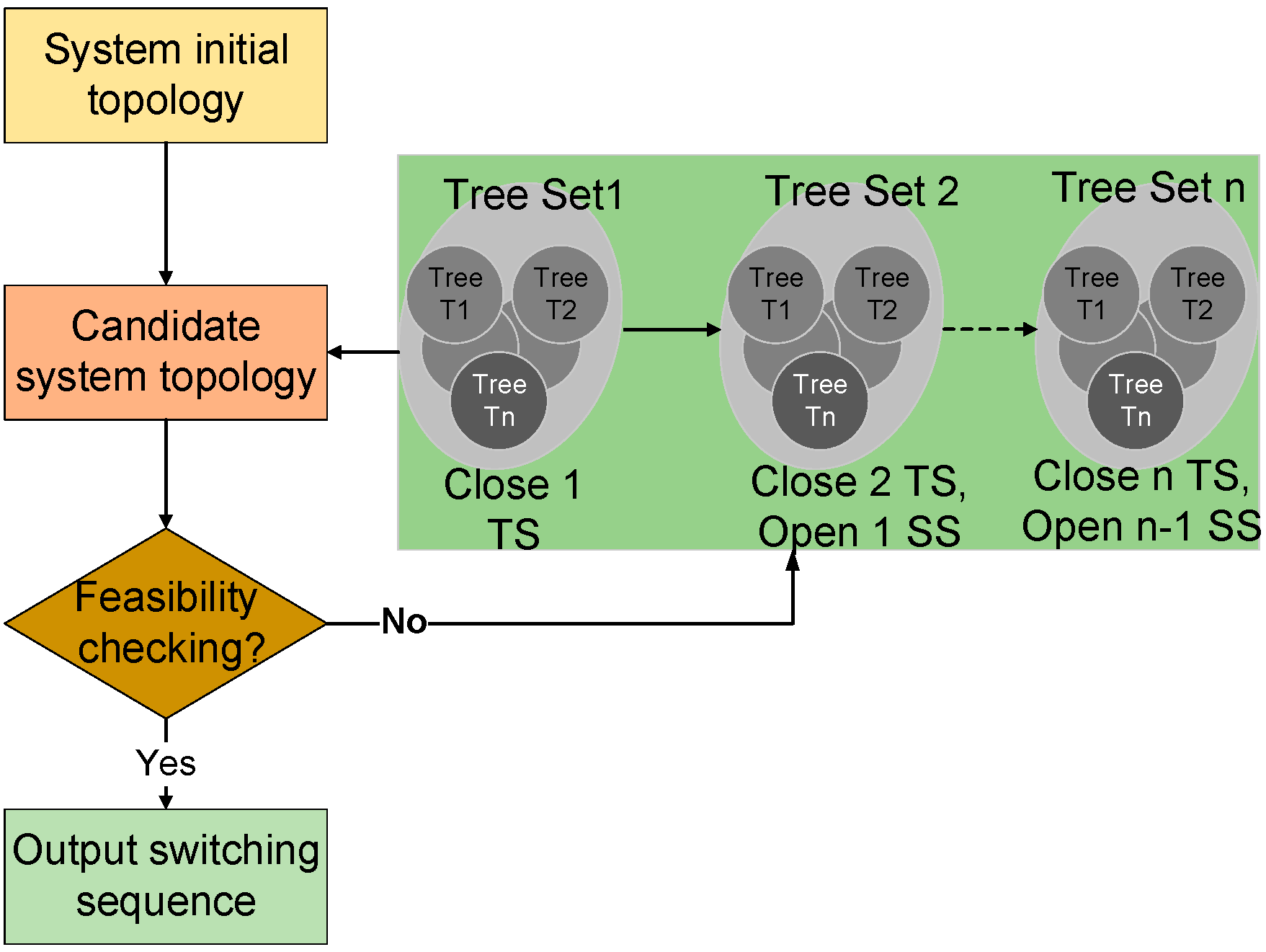
Figure 6.
One-line diagram of the 4-feeder 1069-node test system.

Figure 7.
Restoration path from WSU generator to critical load in Pullman distribution system.

| Index | Fault Location | Switching Operations without Microgrids | Switching Operations with Microgrids |
|---|---|---|---|
| 1 | Z139 | Open: Z46–Z47, Z96–Z89 Close: Z136–Z120, Z53–Z96, Z45–Z90 Partial Restoration, 315.04 kVA load should be shed at F-b | Open: Z50–Z43, Z90–Z92 Close: Z45–Z90, Z73–Microgrid 2, Z136–Z120 |
| 2 | Z23 | Open: Z49–Z50, Z90–Z92 Close: Z78–Z9, Z53–Z96, Z136–Z120 | Close: Z39–Microgrid 1 |
| Tie Switches | T1, T2, T5, T6 and T7 |
|---|---|
| Microgrid switches | Z39–Microgrid 1, Z73–Microgrid 2, Z93–Microgrid 3, and Z160–Microgrid 4 |
| Sectionalizing switches | Z2–Z14, Z10–Z26, Z46–Z47, Z50–Z43, Z90–Z106, Z96–Z89, Z130–Z146 and Z130–Z132 |
| Index | Without RCSs | With RCSs | Improvement |
|---|---|---|---|
| SAIDI (minute/year) | 181.72 | 44.17 | 75.70% |
| SAIFI (/year) | 0.7800 | 0.6548 | 16.05% |
| Step | Active Power (kW) | Reactive Power (kVar) | Apparent Power (kVA) |
|---|---|---|---|
| 1 | 137.8 | 45.44 | 145.1 |
| 2 | 429.6 | 142.7 | 452.7 |
| 3 | 621.1 | 436.6 | 795.1 |
| 4 | 1325 | 455.5 | 1401 |
| Step | 1 | 2 | 3 | 4 | ||||
|---|---|---|---|---|---|---|---|---|
| Critical Load | Voltage (kV) | Voltage (p.u.) | Voltage (kV) | Voltage (p.u.) | Voltage (kV) | Voltage (p.u.) | Voltage (kV) | Voltage (p.u.) |
| City Hall | 0 | 0 | 0 | 0 | 7.914 | 0.993 | 7.889 | 0.99 |
| Hospital | 0 | 0 | 0 | 0 | 0 | 0 | 7.873 | 0.988 |
* The nominal voltage is 7.967 kV.
© 2016 by the authors; licensee MDPI, Basel, Switzerland. This article is an open access article distributed under the terms and conditions of the Creative Commons Attribution (CC-BY) license (http://creativecommons.org/licenses/by/4.0/).
Share and Cite
MDPI and ACS Style
Jiang, Y.; Liu, C.-C.; Xu, Y. Smart Distribution Systems. Energies 2016, 9, 297. https://doi.org/10.3390/en9040297
AMA Style
Jiang Y, Liu C-C, Xu Y. Smart Distribution Systems. Energies. 2016; 9(4):297. https://doi.org/10.3390/en9040297
Chicago/Turabian StyleJiang, Yazhou, Chen-Ching Liu, and Yin Xu. 2016. "Smart Distribution Systems" Energies 9, no. 4: 297. https://doi.org/10.3390/en9040297
Note that from the first issue of 2016, this journal uses article numbers instead of page numbers. See further details here.