1. Introduction
Hydropower has been considered to be a green solution in the current global energy market, fulfilling 16% of demand with installed capacity of 1036 GW [
1]. The global hydropower potential is estimated to be around 4.5 TW and so far one third of the resources have been harnessed [
2]. Hence, the possibility of larger generation potential and better opportunities and scope of research and development would pertain to steady constant power generation in a favorable policy environment.
Most of the unexploited resources are from the Asian and South American region, where higher opportunities also mean larger challenges. Particularly, technical issues invited by sediment erosion (since rivers originating from the Himalayas and the Andes valley consist of a high amount of sediment load) have been considered as a major developmental hurdle. Francis turbines are the medium head type of hydraulic turbines, having stationary (Spiral casing, Stay Vanes and Guide vanes) and rotating components (Runner). Although, guide vanes are stationary, they perform periodic movement based on flow or load variation. These movements are either automatically controlled through servo mechanisms or manually controlled by an operator. In order to allow these movements, small clearance gaps are applied between the facing plates and vane edges. This study is focused on estimation of operational issues invited by these gaps.
Limited researches have been invested in clearance gaps and erosion phenomenon in Francis Turbines. Brekke [
3], studied the effect of clearance gap on the efficiency of turbines. The field experimental observation was performed and found to have a considerable increase in relative efficiency with decreasing clearance gap. These field studies were performed in Kvilldal and Lio One power plants, Norway. Efficiency loss of 1.5%–4% with every increase in gap by 1% of flow channel height was observed. Hence, guide vane leakage loss is one of the most important phenomena for study. Zhao
et al. [
4] studied leakage flow through the clearance gap between two stationary walls using a simplified model developed at Water Power Laboratory, Norwegian University of Science and Technology, Norway. An empirical model was developed for quick prediction of leakage flow. The simplified model was similar to the clearance gap in Francis turbines. The research suggested implementation of outcome in turbine system, for comparative validation of empirical relation. Eide
et al. [
5] studied the effect of clearance gap induced by head cover deflection and its effect on the flow around guide vanes. Flow velocity from middle to top span was found to be dependent on gap size.
The research gap lies in identifying the post erosion flow phenomena in Francis turbine. Peripheral researches were performed in different time intervals but lack the correlation between them. This paper unifies major prospects related to the clearance gap effect with reference to that research. Theoretical exploration of leakage flow and interrelationship with erosion through complete Francis turbine simulation are major objectives of this work.
2. Guide Vanes in Francis Turbine and Its Erosion
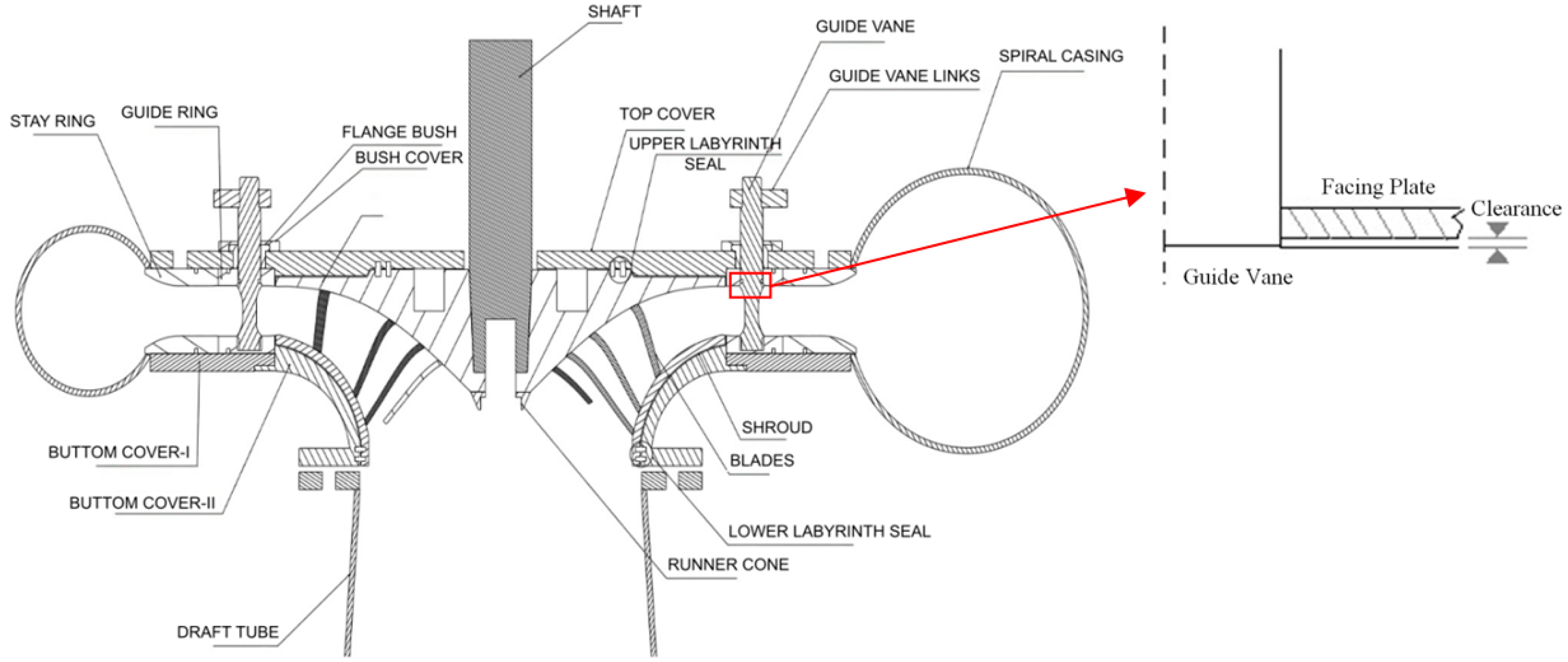
Figure 1 show cross sectional view of a Francis turbine with the location of clearance gap. Guide vanes are responsible for flow governance in the turbines. The gaps on the passage and the presence of the bluff body and shaft promote leakage and secondary wake flow respectively.
In a Francis turbine, internal pressure decreases with decreasing radius of the region.
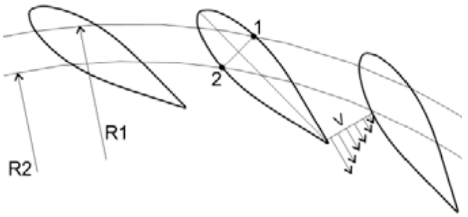
Figure 2 is the guide vanes in Francis turbine. From
Figure 2, point 1 has higher pressure compared to point 2, which forces water to cross the vane from gaps, to reach point 2. This secondary flow is leakage and cross flow through the gaps. This flow energy remains un-utilized and disturbs the main flow stream. It has been considered a major part of internal losses. Brekke, 1988 in
Figure 3, illustrates losses at different regions from inlet to outlet of a High Head Francis Turbine. The possible total loss in a high head Francis turbine is around 5%–6%, during the operation in Best Efficiency Point (BEP). With minimum dry gap, losses of around 1.5% occur through leakage. Hence, leakage due to losses is one of the major portions of loss inside the turbine [
7].
Leakage has a considerable effect on the flow dynamics (disturbance in the flow streamline due to cross flow), forming localized secondary flow, which ultimately have both hydraulic and mechanical effect in the turbine. In presence of sediment particles, secondary flow, i.e., horseshoe vortex, erodes both the facing plate and guide vane surfaces, further increasing the gap. Below, we present some of the similar cases observed.
Sediment Erosion in Guide Vanes
Guide vanes have the prime function of conversion of pressure to kinetic energy; hence, the cascade system of guide vane has the highest acceleration and absolute flow velocity. Flow phenomena like turbulence, secondary flow, leakage and acceleration cause erosion in guide vanes. In particular, the leading edge, top and bottom, shafts and faces of guide vanes were found to have higher erosion. The characteristics of sediment particles; shape, size and mineral content with the property of guide vane material and flow dynamics; play important role in erosion severity of exposed turbine components, including guide vanes.
Figure 4 shows the erosion pattern in guide vanes of Francis Turbine installed at Kaligandaki A (KG-A) Hydropower Project, Sunkoshi Hydropower Project (SKHP) (Nepal) and Bhilangana Hydropower Project (BHPP) (Utarakhada, India). The first author of this paper collected these images and data during his field visits. Almost all the runoff hydropower projects installed in the rivers originating from the Himalayas with Francis Turbines has a similar kind of problem. This leads to increased losses in the turbine, periodic shut down, frequent maintenance, operation of the consecutive components,
etc. At an operation of 16,500 h at KG-A, Nepal, clearance gaps of up to 10 mm were found in a guide vane with height 500 mm. These gaps were identified to have been affecting automatic operation of inlet valve. Trailing edge gaps were found to have higher amount of erosion compared to leading side. Similar cases were observed in almost all hydropower plants operating in sediment laden flow.
3. Computational Model
This analysis used the geometry of model Francis turbine scaled based on IEC 60193, optimized for sediment handling by Turbine Testing Lab (TTL), Kathmandu University [
8]. It was developed in reference to Jhimruk Hydropower Center (JHPC), Nepal. Separate domains for Spiral Casing, Stay Vanes, Guide Vanes, Runner and Draft tube were defined. This project is a continuation of earlier research activity performed by TTL with a vision of developing an erosion resistant Francis Turbine.
3.1. Computational Domain
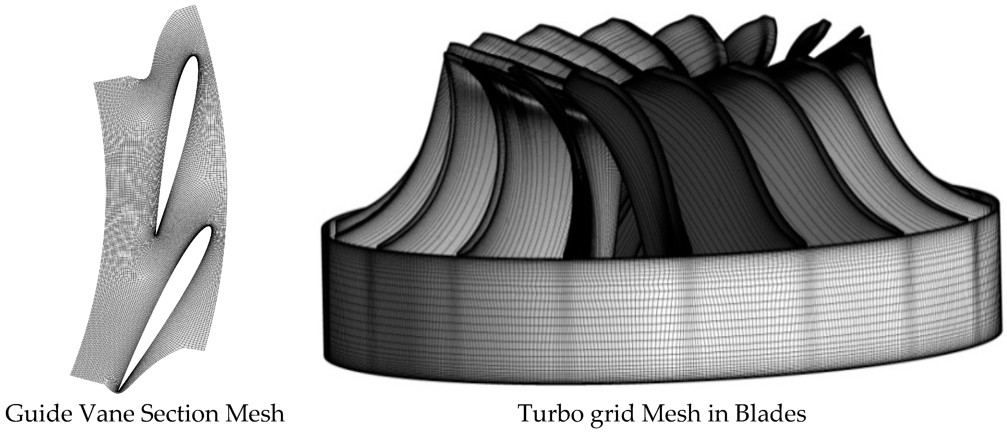
The meshes were generated considering 5% convergence criteria in Grid Independent Analysis with an interval of 1.5 times mesh size. Separate computation was performed for each of the domains with its operating boundary conditions. Velocity was monitored. ICEM (a powerful meshing software) and Turbogrid meshing features of ANSYS (Analysis System software) 14 available at State Key Laboratory of Hydroscience and Engineering, Tsinghua University, China were used. Blades and Stay vanes were meshed using Automatic Topology Mesh (ATM) optimized features of Turbogrid, whereas Spiral Casing, guide vanes and Draft tube were meshed using manual block refinement in ICEM to generate structural mesh. The flow cascade consists of 17 runner vanes, 24 guide vanes and 24 stay vanes. A single 3 Dimensional guide vane flow cascade was developed to generate high quality mesh. Stay vanes, guide vanes and runner vanes were transformed in commercial software ANSYS (CFX-pre).
Table 1 presents mesh details of the components.
In contradiction with the practice, this computational approach implemented the practical design of guide vane with shaft, fillets and clearance. Seven different guide vane domains with clearance gaps of 0, 0.5, 1, 1.5, 2, 2.5 and 3 mm were prepared. The selection of gaps was based on the site observation, prototype to model relation and computational result in
Figure 5 shows hex dominant mesh in guide vanes and the runner.
3.2. Preprocessing
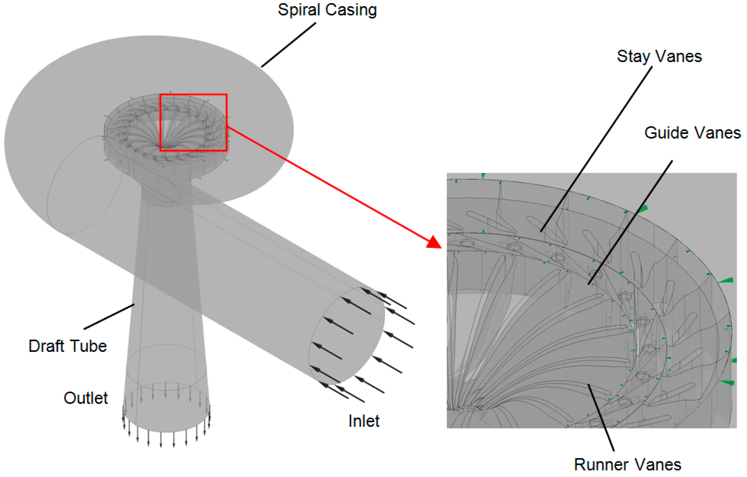
Mass flow inlet of 227 kg/s and pressure outlet to atmospheric pressure was used as boundary conditions, since this has been found to be robust with fluid flow simulation. Rests of the boundaries were defined as interfaces and no slip walls. Frozen rotor interface was selected between the stator and rotor. Turbulence was simulated using Shear Stress Transport Turbulence model, due to its robustness in predicting both near and away wall boundary flows.
Figure 6 shows the boundary condition in flow passages.
The Root Mean Square (RMS) for solution convergence has been selected at 10−4. All computations were performed in a cluster computer with eight CPUs of Intel 5645, 2.4 GHz processor, 96 GB RAM and 2 TB storage.
4. Solver Theory
The finite volume analysis in the system was performed using Reynolds Averaged Navier-Stokes equations with mass, momentum and energy conservation represented by;
The turbulence flow modeling was found to be satisfactory for separated flows with the two equation Shear Stress Transport model. Hence, it was implemented for the turbulence prediction at boundary layer and away from boundary regions for separated flows.
Discrete numbers of particles were tracked over the free stream flow using the Langrangian Particle Tracking Method. The Computational Fluid Dynamics (CFD) code incorporates particle tracking and fluid-particle solution coupling for approximation of particle fluid interaction, through the variation in mass resulting difference of velocity. The sand path in continuous flow domain is described by the Equation (2). The particles drag in water, buoyancy, Coriolis Effect, virtual mass and pressure gradient forces, during which its motion in fluid is described by Equation (2) in fluid particle multiphase flow.
When sand mixed with water strikes the wall of the turbine, the resultant erosion pattern is defined by the erosion models. Tabakoff erosion model has been found to be reliable compared to others for the analysis of erosion in Francis turbines. Hence, erosion rate density is defined by Equation (3) and is a function of particle characteristics, turbine materials, velocity and angle [
9].
Action of particle as it hits the wall of the domain was defined with parallel and perpendicular restitution coefficient. Restitution coefficient was used to define particle action after it strikes the wall. Neopane suggested the perpendicular and parallel coefficients to be 0.9 and 1 respectively [
10].
5. Result and Discussion
The computational analysis was performed in a series of stages. Steady state analysis of water—sand flow was performed to predict the material loss in the gap regions. Then single phase flow analyses were performed to predict effects that might occur due to these gaps. Below is the description of the result obtained.
5.1. Clearance Gap Approximation
Thickness depletion analysis through CFD was performed in the prototype design of the turbine. Guide Vane and its periphery were observed. The designed clearance gap has been used for analysis purposes.
At Jhimruk Hydropower Center, a higher concentration of sand has been found in the range from 0 to 90 µm with a higher percentage of quartz, hence, considering the effect of sand size of 30 µm and shape factor 1, this analysis was performed [
11]. At best efficiency point, the maximum erosion at leading edge of guide vane was observed. The study priority was given to erosion in clearance gaps and was found to be distributed over gap regions in both the leading and trailing edges and in facing plates.
CFD analysis gives Erosion Rate Density (ERD). With some additional processing, thickness depletion was computed. Equation (4) was used to calculate the loss of thickness.
where
he is the eroded height, ERD is the erosion rate density,
Time is the time of operation and
ρm is the density of material.
The observational time of about 1 year,
i.e., around approximately 7000 h has been considered, variable area is cancelled in equation terms and density of turbine material is 7850 kg/m
3, hence eroded depth was calculated. The erosion model of Tabakoff and Grant was used since it was defined for Steel-Sand interaction.
Figure 7 is the result with around 3 mm loss in the facing plate and a similar amount of loss in the guide vane edges.
In 2001, at Nepal Hydro and Electric Company, Butwal, when the turbine from JHPC was observed in an operation of around 4212 h, facing plate depth was found to be around 4 mm and the height of the guide vane was also decreased [
12]. In this further computation, the 0.46 times scaled IEC standard model has been considered with simplified gap spaces of up to 3 mm in an interval of 0.5 mm to observe the effect.
5.2. Leakage Flow Rate
Leakage flow through varying clearance gap using computational and empirical relation was calculated. Zhao
et al. [
4], through a series of experiments and computational study in a simplified setup, developed an empirical relation (Equation (5)) for estimating the leakage flow rate. It was derived from the Bernoulli and continuity equation predicting the orifice flow in the gap. The flow region, clearance gaps and flow characteristics in experimental setup justifies the flow similarity.
where
A is the cross sectional area,
Δh is the pressure difference in terms of water head and
µ is the coefficient of flow. Equation (6) was developed based on the regression of the experimental data obtained for various clearance gap and flow conditions. Hence, the flow coefficient was calculated using Equation (6) which is a function of the ratio of clearance length and gap;
where,
l/
s is the ratio of clearance length and gap.
A user defined surface feature in commercial CFD post processing, with four points coordinate defined by .csv (Comma Separated Valued) data file was used to define a finite surface along the camber line in the gap. At this surface, average leakage flow rate across the gap was calculated. Pressure measured across the vane was used in the empirical relation for flow rate (Equation (5)).
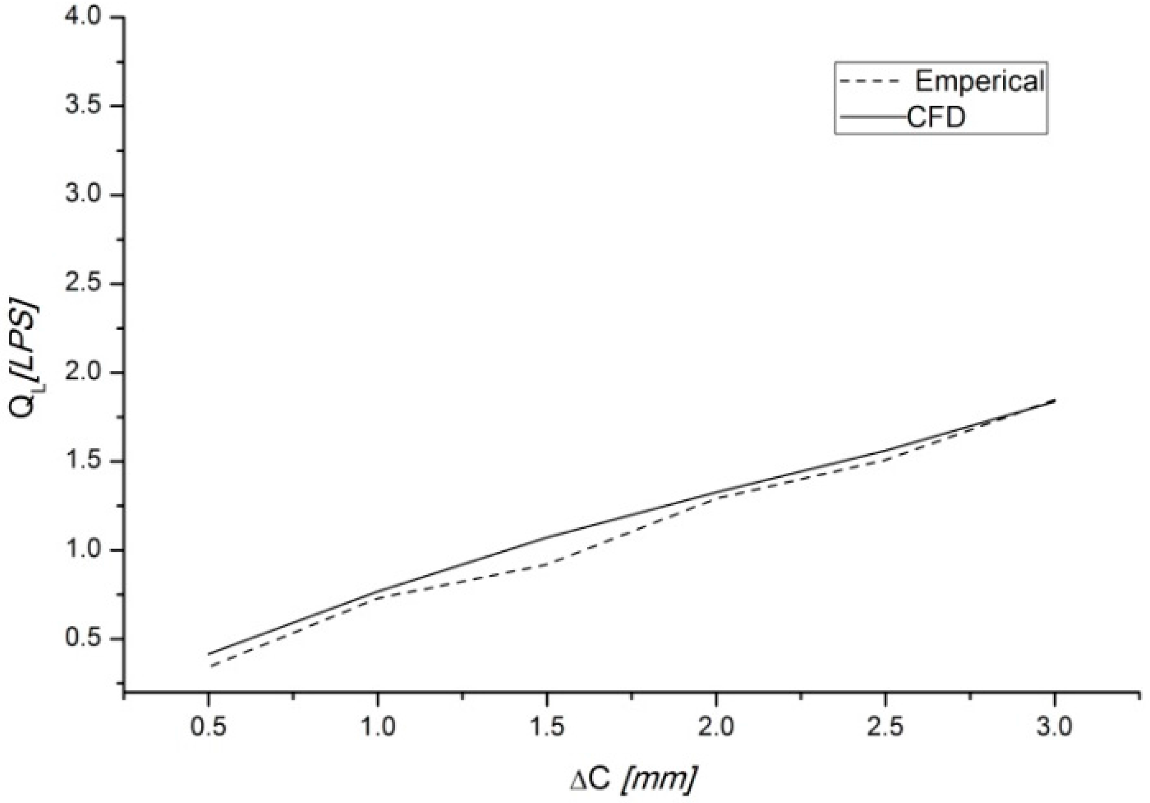
Figure 8 shows a matching relationship between empirical and computational results obtained from the analysis. In a cascade with 9.45 Liter Per Second (LPS), flow leakage flow from 0.4 to 1.7 LPS was calculated. Maximum deviation of 17% was found in 1.5 mm gap whereas the rest of the results were below 10%.
5.3. Hydraulic Performance ΔC
Figure 9 shows relative hydraulic performance of the turbine at varying clearance gaps. A comparative chart between relative efficiency loss, relative energy drop and relative pressure drop has been presented. The total pressure and kinetic energy at Guide Vane outlet, mechanical efficiency of the turbine and average pressure in the Spiral Casing were observed. All the differences were computed in reference to the obtained values at 0 mm clearance gap. It has been found that, with increase in clearance, gaps losses increases. The proportion of the efficiency drop has been found to be sharply changing with a significant amount of losses. Around 3% efficiency loss, for increase in gap by 1% of Passage height is observed. This is similar to the observation by Brekke [
7]. Spiral casing pressure was found to drop by 2% with every 1 mm increase in the gap. This can be a major reason behind the problem in pneumatic flow control systems for flow regulation since, during inspection; external mechanical failures were not found. These proportions and trends in the energy change is the result of un-utilized leaked cross flow through gaps.
5.4. Nature of Leakage Flow
So far, literature has been concerned with the trending velocity profile in the gaps between the two surfaces compared to the flat plate flow. However, the flow nature at the gap varies in upper and lower regions due to the presence of edge of guide vane in one side and the flat facing plate on the other side.
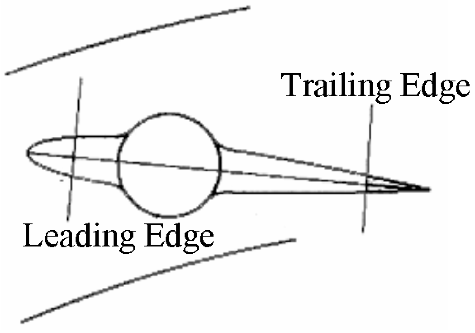
Figure 10 shows the location of plane for velocity observation.
The study was performed considering a percentage region for common comparison of the phenomena.
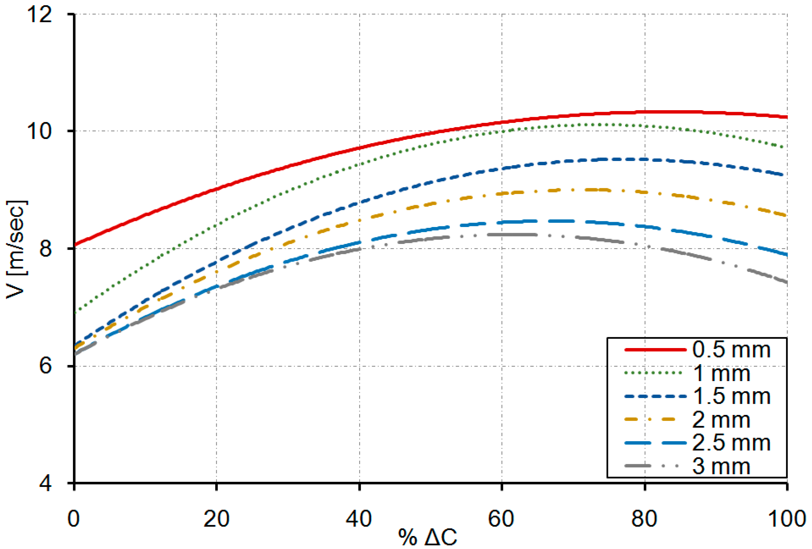
Figure 11 shows velocity distribution over a gap between facing plate and guide vanes at leading edge, where 0 refers to the region near the guide vane edge and 100 refers to the region near the facing plate edge. It was found that the velocity profile is different from general flat plate flow. The magnitude of velocity near the facing plate boundary was found to be higher compared to near guide vanes. This may be due to the continuous flow at the upper region and interrupted flow at the lower region because of the sudden projection of guide vanes geometry. With increasing clearance gap, velocity is found to be decreasing, as defined by continuity equation for the orifice flow. The stiffness in the graph decreases with the increase in the gap since, with larger gaps, flow tends to behave like in a continuous flat plate system.
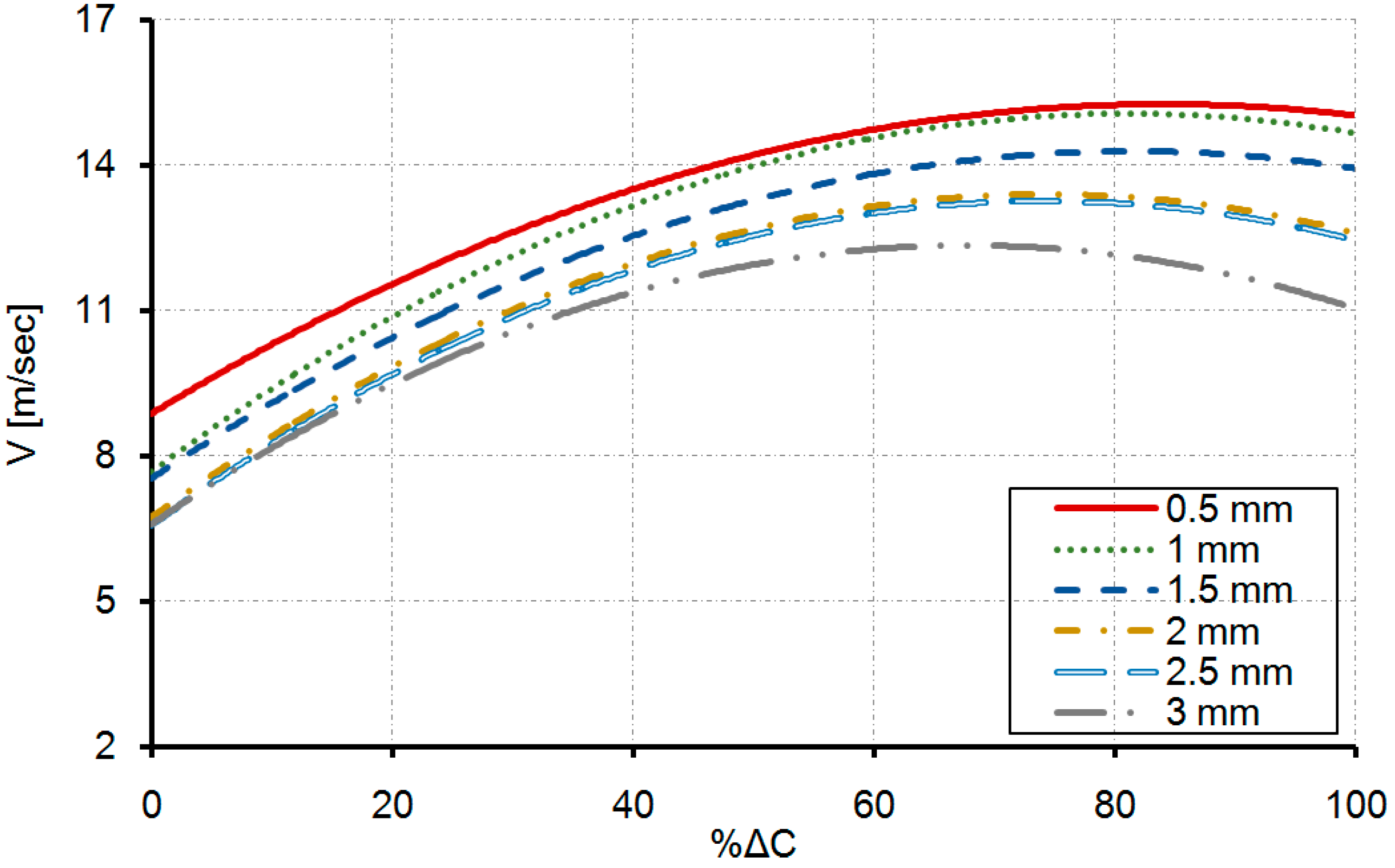
Figure 12 shows the graphical representation of the velocity distribution in the trailing edge. Unlike the leading edge, the velocity distribution seems to be close in all the cases, although the decreasing pattern with increasing gap is similar. The stiffness pattern is also similar to the leading edge. The magnitude of the velocity distribution is higher compared to the leading edge because of the high acceleration with decreasing radius.
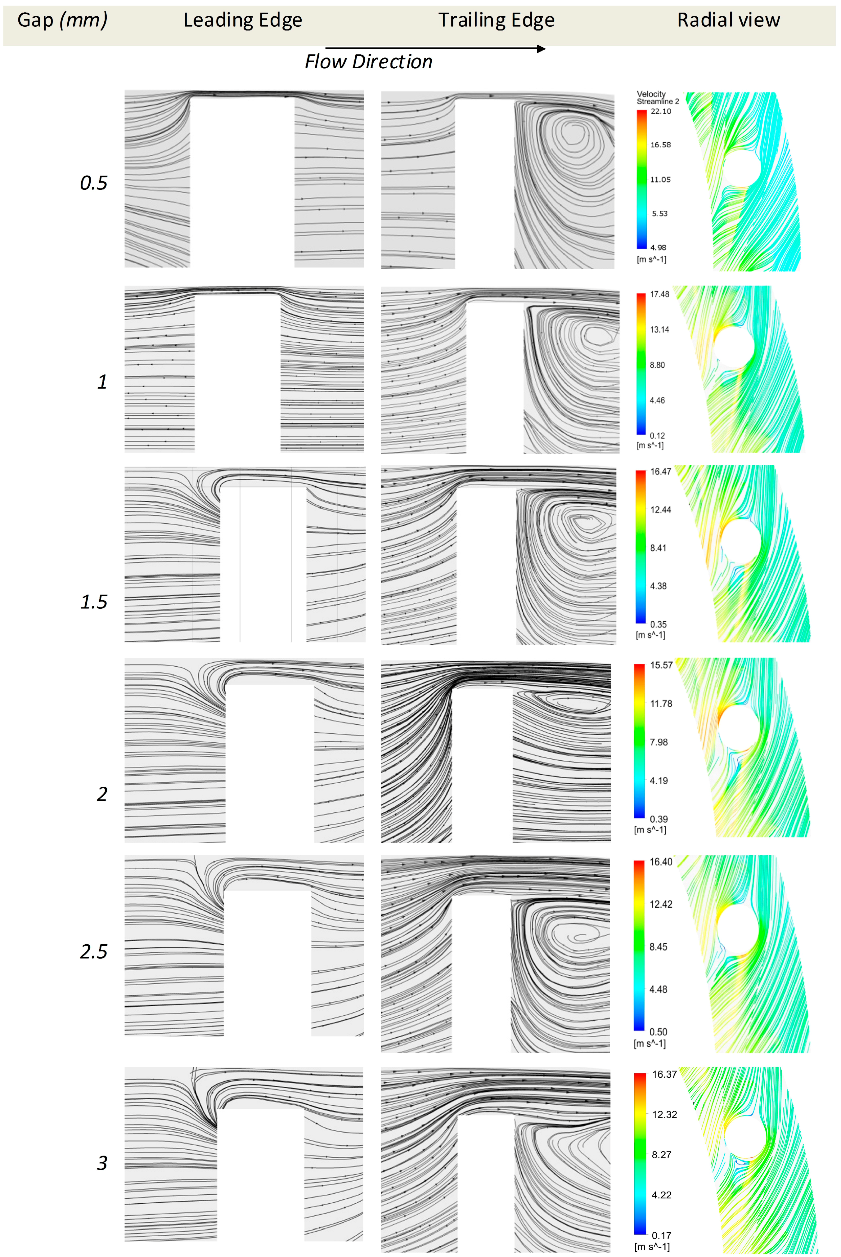
Figure 13 is the surface streamline plot of flow in leading edge, trailing edge and radial gap view at various clearance gaps. Based on general observation, leakage flow through clearance gap can be divided as upstream, passage and downstream.
It has been observed that flow at the leading edge of the guide vane has large turbulence and accumulation at the upstream region. With larger gap, higher flow affected regions were observed, because of the substantial pressure variation across the vanes. At the trailing edge, along with flow accumulation upstream, an unsteady turbulence vortex was observed downstream. This leakage flow vortex has high turbulent intensities which may result dynamic operational issues. The smaller the gap, the more intense is the vortex, which eventually gets fade because of the change in leakage flow velocity. This turbulent vortex is formed due to flow rolling during interaction of leakage flow with primary flow, while detaching from guide vane tip [
13]. The leading edge downstream is found to have fade turbulence since the leakage induced turbulence vortex is largely dependent on the thickness of the guide vane [
14]. Apart from this, the radial flow surface plot shows that the flow direction deviation is larger in the trailing edge compared to the leading edge.
At the radial region in the gap, a sudden change in the flow direction around gap was observed, due to leakage cross flow. This change in direction is highly intense at the trailing edge compared to the leading edge, resulting higher cross flow across the vanes. During the radial flow, the shaft acts as a cylindrical bluff body, the flow across which forms curl and wake, resulting another secondary flow in the turbine [
15].
6. Conclusions and Recommendation
Francis turbine operating in sediment laden water has been found to have severe erosion, affecting the designed flow passage. In particular, guide vanes were found to have erosion in leading edges, trailing edges and height along with the adjacent component, the facing plate. Observation in
Figure 7 showed the location and severity of erosion in guide vanes and its periphery. This study focuses on clearance gap erosion in guide vanes on the basis of three experimental and observational backgrounds: clearance gap erosion in the facing plate of Jhimruk Hydropower Plant, on site study of effect on performance with clearance gap, and study of flow through a simplified test rig.
Here, a possible process to estimate eroded thickness by defining additional equation in post processing analysis has been presented. A computational study was performed considering 7000 operating hours, and a total gap of around 6 mm at the region were found. Further analysis with the scaled model was performed. The analysis considered the real type operating scenario of the guide vane by considering various clearance gaps that may have been induced with the erosion. Leakage flow estimation and comparison with the established empirical relation has been performed along with detailed study of the nature of the leakage flow with varying gaps.
Leakage flow rate has been found to increase with an increase in the gap, which consequently increases the hydraulic losses, pressure drops and relative efficiency loss in the turbine. The velocity profiles in gaps of trailing region were found to be higher compared to the leading side. This shows that the velocity in the region near to the guide vane is lower compared to the facing plate because of obstruction in the developed flow. As the gap increases, it tends to be close to the flow in s parallel pipe. With an increase in gap, the induced secondary vortexes becomes larger and fade in the trailing region whereas, at the leading edge only fade vortexes were observed. This may be because of a difference in the thickness of vanes and amplitude of pressure difference. The cross flow velocity decreases with increasing gaps; hence, in power plants it has been observed that the erosion rate in the clearance region decreases with time.
Future study is essential in performing accelerated tests for clearance gaps erosion and their effect upon the flow considering the actual operating conditions.
Acknowledgments
We acknowledge National Science Foundation of China “Grant number 51179090” for the financial support in the project. We are also thankful to Vipassana Paudel and Rijju Sigdel for helping us come with this work.
Author Contributions
Ravi Koirala, is a researcher for a part of international cooperation between Tsinghua University and Kathmandu University. This is one of his major objectives in the research, where his contribution is in computational simulations and drafting of paper. Baoshan Zhu, is an associate professor at Department of Thermal Engineering, Tsinghua University. He is a supervisor for this master’s work. He has contributed in computational methodology, results sorting and manuscript revision along with all the financial related financial matters. Hari Prasad Neopane, is an associate professor at Department of Mechanical Engineering, Kathmandu University. He is a supervisor for this master’s work. He contributed in concept formulation, computational methodology and manuscript revision.
Conflicts of Interest
The authors declare no conflict of interest.
Abbreviations
The following abbreviations are used in this manuscript:
| UP | Particle Velocity |
| mp | Mass of particle |
| FD | Drag Force |
| FB | Buoyancy force |
| FR | Force due to domain rotation |
| FVM | Virtual mass force |
| FP | Pressure gradient force |
| ΔC | Clearance gap |
| FBA | Basset force |
| E | Erosion Rate Density |
| K1 | Model constant |
| VP | Particle impact velocity |
| γ | Impact angle |
| µ | Flow coefficient |
| QL | Leakage Flow Rate |
| BEP | Best Efficiency Point |
| IEC | International Electro technical Commission |
| ATM | Automatic Topology Mesh |
| RMS | Root Mean Square |
| RAM | Random Access Memory |
| CFD | Computational Fluid Dynamics |
| LPS | Liter Per Second |
References
- International Hydropower Association. Hydropower Status Report; International Hydropower Association: London, UK, 2015. [Google Scholar]
- HydroPower and Dams. World Atlas; Aqua Media International Ltd.: Surrey, UK, 2009. [Google Scholar]
- Brekke, H. The influence of the Guide Vane Clearance Gap on Efficiency and Scale Effect. In Proceedings of the IAHR Symposium on Modern Technology in Hydraulic Energy Production, Belgrade, Yugoslavia, 11–14 September 1990; Volume 15.
- Zhao, W.; Billdal, J.T.; Nielsen, T.K.; Brekke, H. Study on the Leakage Flow through a Clearance Gap between Two Stationary Walls. In Proceedings of the IAHR Symposium on Hydraulic Machinery and Systems, Beijing, China, 19–23 August 2012; Volume 26.
- Eide, S.; Brekke, H. Analysis of the Head Covers Deflection and the Leakage Flow in the Guide Vanes. In Proceedings of the IAHR International Symposium on Hydraulic Machinery and System, Lausanne, Switzerland, 9–12 September 2002.
- Koirala, R.; Chitrakar, S.; Panthee, A.; Neopane, H.P.; Thapa, B. Implemntation of Computer Aided Engineering for Francis turbine development in Nepal. J. Manuf. Eng. 2015. [Google Scholar] [CrossRef]
- Brekke, H. The influence from the Guide Vane Clearance Gap on Efficiency and Scale Effect for Francis Turbine. In Proceedings of the IAHR Symposium on Progress within Large and High Specific Energy Units, Trondheim, Norway, 20–23 June 1988; Volume 14, pp. 825–837.
- Thapa, B.S.; Thapa, B.; Dahlhaug, O.G. Current research in hydraulic turbines for handling sediment erosion. J. Energy 2012, 47, 62–69. [Google Scholar] [CrossRef]
- ANSYS Inc. CFX-pre Theory Guide; ANSYS Inc.: Canonsburg, PA, USA, 2014. [Google Scholar]
- Neopane, H.P. Sediment Erosion in Hydraulic Turbines. Ph.D. Thesis, Norwegian University of Science and Technology, Trondheim, Norway, 2010. [Google Scholar]
- Basnyat, S. Monitoring sediment load and its abrasive effects in Jhimruk Hydropower Plant, Nepal. In Proceedings of the Optimum Use of Run-off-River Conference, Trondheim, Norway, 21–23 June 1999.
- Thapa, B. Sediment Erosion in Hydraulic Machinery. Ph.D. Thesis, Norwegian University of Science and Technology, Trondheim, Norway, 2004. [Google Scholar]
- You, D.; Wang, M.; Moin, P.; Mittal, R. Effects of tip-gap size on the tip-leakage flow in a turbomachine cascade. Phys. Fluids 2006, 18. [Google Scholar] [CrossRef]
- Tang, G. Measurement of the Tip-Gap Turbulent Flow Structure in a Low-Speed Compressor Cascade; Virginia Polytechnic Institute and State University: Blacksburg, VA, USA, 15 May 2004. [Google Scholar]
- Princeton University. Draft of Blunt Bodies and Streamlined Bodies. Available online: https://www.princeton.edu/~asmits/Bicycle_web/blunt.html (accessed on 20 October 2015).
© 2016 by the authors; licensee MDPI, Basel, Switzerland. This article is an open access article distributed under the terms and conditions of the Creative Commons by Attribution (CC-BY) license (http://creativecommons.org/licenses/by/4.0/).
