Article

A New Robust Decoupled Control of the Stator Active and Reactive Currents for Grid-Connected Doubly-Fed Induction Generators

1
Graduate School of Engineering, Osaka University, 2-1 Yamada-oka, Suita, Osaka 565-0871, Japan
2
Osaka Gas Co., LTD, 6-19 Torishima, Konohana-ku, Osaka 554-0051, Japan
*
Author to whom correspondence should be addressed.
Energies 2016, 9(3), 179; https://doi.org/10.3390/en9030179
Submission received: 13 January 2016 / Revised: 3 February 2016 / Accepted: 3 March 2016 / Published: 9 March 2016
(This article belongs to the Special Issue Microgrids 2016)

Abstract

:
This paper addresses the grid-connected variable speed doubly-fed induction generator, and proposes a new decoupled control to replace the conventional decoupled active and reactive powers (P-Q) control. The proposed decoupled control is based on decoupling the stator active and reactive currents, in contrast with the conventional decoupled P-Q control, which is based on decoupling the stator active and reactive powers by forcing the stator d- or q-voltage to zero. The proposed decoupled control has all the advantages of the conventional decoupled P-Q control such as constant switching frequency and robustness against slip angle inaccuracy, and it has some additional advantages: The proposed control requires less machine parameters; for the controller design, it requires the stator-to-rotor turns ratio only; for the online calculation, it does not requires any machine parameter. The proposed decoupled control is more flexible and robust since the control is independent of the grid voltage orientation. It is robust against variation in the grid voltage amplitude. Several experiments are carried out using a 1.1 kW doubly-fed induction generator (DFIG), and the results support the proposed decoupled control and demonstrate some of its advantages.

Graphical Abstract

1. Introduction

Currently, improving the efficiency of electric generation systems is the focus of a lot of attention and research. Better efficiency brings economic benefit and improves the return-on-investment. It also means reducing CO2 emissions for fuel-fired generation systems such as diesel and natural gas engines. Variable speed operation is an attractive solution to improve the efficiency.
Variable speed operation has several advantages compared with fixed speed operation for different generation systems: For wind turbines, it increases the power production, improves the power quality, and reduces mechanical stresses [1,2]; for internal combustion engine-based generation systems, it reduces the fuel consumption, increases the maximum attainable output power, and achieves safe operation at low load condition [3,4,5]; for hydro-generation systems, it provides remarkable improvements in energy and hydraulic conditions, improves the efficiency, and increases the turbine lifetime [6,7].
Variable speed generation systems, however, must generate a fixed output frequency regardless of the generator’s speed which requires special configuration and control. This paper addresses the grid-connected operation only, and it adopts the doubly-fed induction generator (DFIG) which is widely used in variable speed wind turbines due to its advantages such as smaller converter size, which is a fraction of the generator’s rating, complete control of active and reactive powers, etc. [8,9,10]. In a DFIG system, the DFIG’s rotor is connected to the grid through a back-to-back converter, whereas the stator is connected directly to the grid as shown in Figure 1.
The early control method of the grid-connected DFIG, such as that in [11,12,13], is based on the vector control. The vector control method decouples the rotor current in the synchronous reference frame into active and reactive components and controls them separately using PI (proportional-integral) controllers in a closed-loop configuration which is referred to as the rotor current loop. The rotor current references for the rotor current loop are calculated from the desired power references using the DFIG model. Although the vector control method achieves constant switching frequency and low power ripples, it requires accurate information of the DFIG parameters and is sensitive to slip angle inaccuracy.
More recently, direct torque [14,15] and direct power control [16,17] are introduced to reduce the control dependency on machine parameters and to reduce the calculation complexity. However, these methods produce high power and/or torque ripples and a variable switching frequency which complicates the design of the AC harmonics filter because it should be designed to absorb broadband rather than a single frequency [18]. Several modifications have been proposed in the literature to overcome the shortcomings of the direct control methods. For example, an integral sliding mode with the space vector modulation scheme and a predictive algorithm were introduced to the direct torque control in [19] and in [20] respectively. Predictive algorithms were also introduced to the direct power control as in [21,22]. These methods have successfully reduced the ripples and have produced constant switching frequency, but they suffer from additional drawbacks such as complicated online calculations, and the sensitivity to machine parameters was not discussed.
The decoupled P-Q (active and reactive powers) control was developed from the vector control method by introducing an outer control loop which generates the rotor current references from the stator active and reactive powers [23,24,25]. Consequently, the decoupled P-Q requires less number of DFIG’s parameters than the vector control, while having the same advantages.
This paper proposes a new decoupled control to replace the conventional decoupled P-Q control. The proposed control is based on decoupling the stator current instead of the stator power. The proposed decoupled control has all the advantages of the conventional decoupled P-Q control, and it has some additional advantages: It requires less DFIG parameter; the online calculation is independent of the DFIG parameters, while the controller design requires the stator-to-rotor turns ratio only. The stator active and reactive currents are always decoupled during steady-state regardless of the stator voltage orientation in the synchronous reference frame; this gives the proposed control more flexibility and robustness. The proposed decoupled control can be considered independent of variations in the DFIG parameters due to saturation. The response of the proposed control is independent of the grid voltage amplitude which makes it suitable for remote wind turbines.
Most of the control methods for grid-connected DFIG require knowledge of the DFIG’s rotor position which can be measured using a mechanical encoder or estimated using a software estimator. In this paper, a mechanical encoder is used. Software estimators as those in [26,27,28] can also be used to avoid the drawbacks of the mechanical encoders such as increased system cost, increased wiring complexity, and reduced reliability [29].
This paper provides a brief review of the conventional decoupled P-Q control; then, the proposed decoupled control is introduced, and the sensitivity analysis for inaccuracy in the slip angle is provided. Finally, experiments using 1.1 kW DFIG are carried out to validate the proposed method.

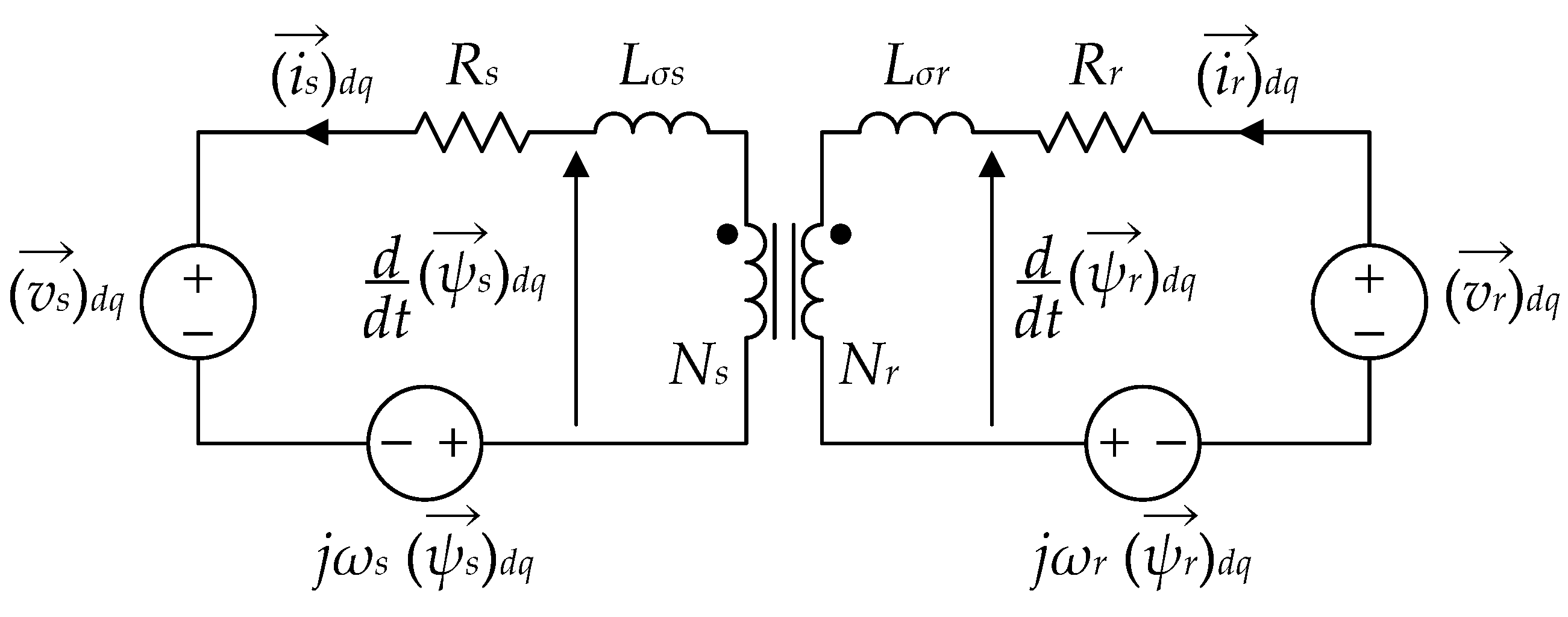
2. Conventional Decoupled P-Q Control

The decoupled P-Q control is carried out in the synchronous reference frame (dq-frame). In this paper, the stator voltage orientation is adopted where the d-axis is aligned with the stator voltage using a PLL (phase-locked loop) circuit similar to that in [30]. The equivalent circuit of the DFIG in this-frame is shown in Figure 2 [31] where the generator notation for the stator current is adopted.
The stator active and reactive powers can be calculated using the stator d- and q-voltages and currents as in:
{ P s = i sd v sd + i sq v sq Q s = i sd v sq i sq v sd
The active and reactive powers in Equation (1) become decoupled when the stator q-voltage is forced to zero by the PLL circuit. Then, the stator active and reactive powers are given by:
{ P s = i sd v sd Q s = i sq v sd
Considering the stator voltage well-regulated and constant, the relation between the stator power and the stator current is linear, and PI controllers can be used to generate the stator d- and q-current references from the active and reactive powers respectively.
The voltage equation across the DFIG’s stator side during steady-state is given by:
( v s ) dq = [ R s + j ω s ( L s + L σ s ) ] ( i s ) dq + j ω s L m ( i r ) dq
Rearranging Equation (3) and neglecting the stator winding resistance Rs and the stator leakage impedance compared with the stator impedance, the relation between the rotor current and the stator current is given by:
( i r ) dq = N s N r ( i s ) dq j ( v s ) dq ω s L m
Equation (4) is used to estimate the rotor current references which requires the stator-to-rotor turns ratio and the mutual inductance.
The block diagram of the conventional decoupled P-Q control is depicted in Figure 3.

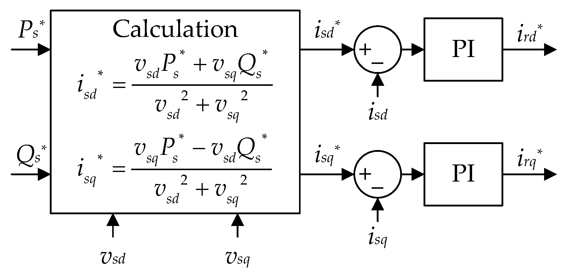
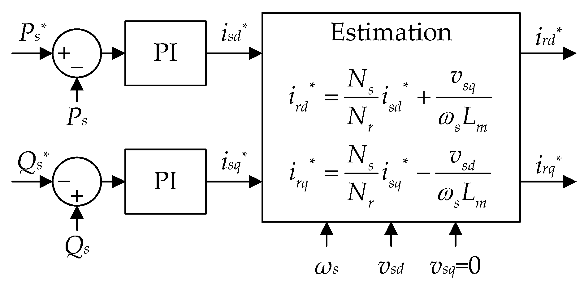
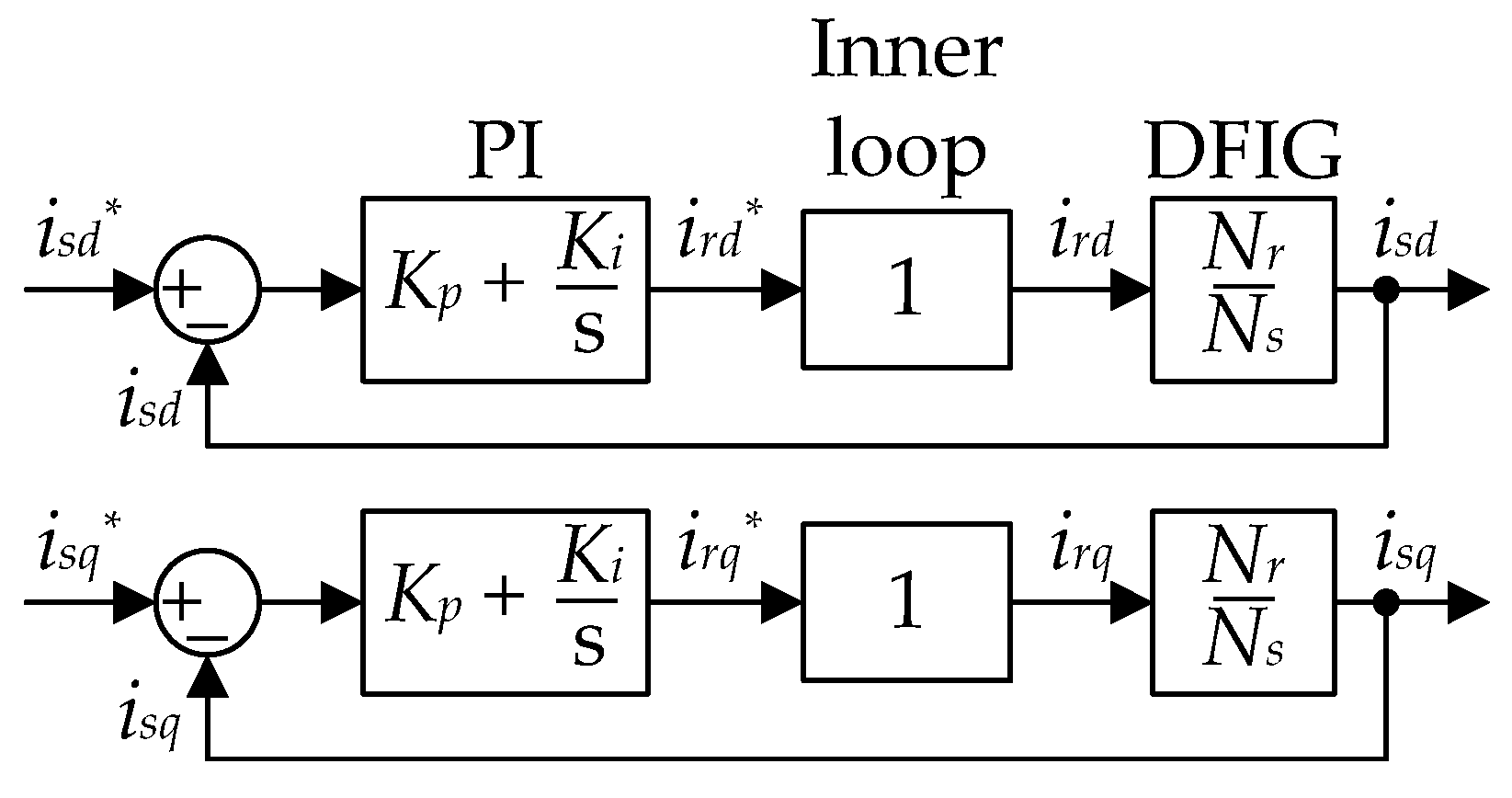
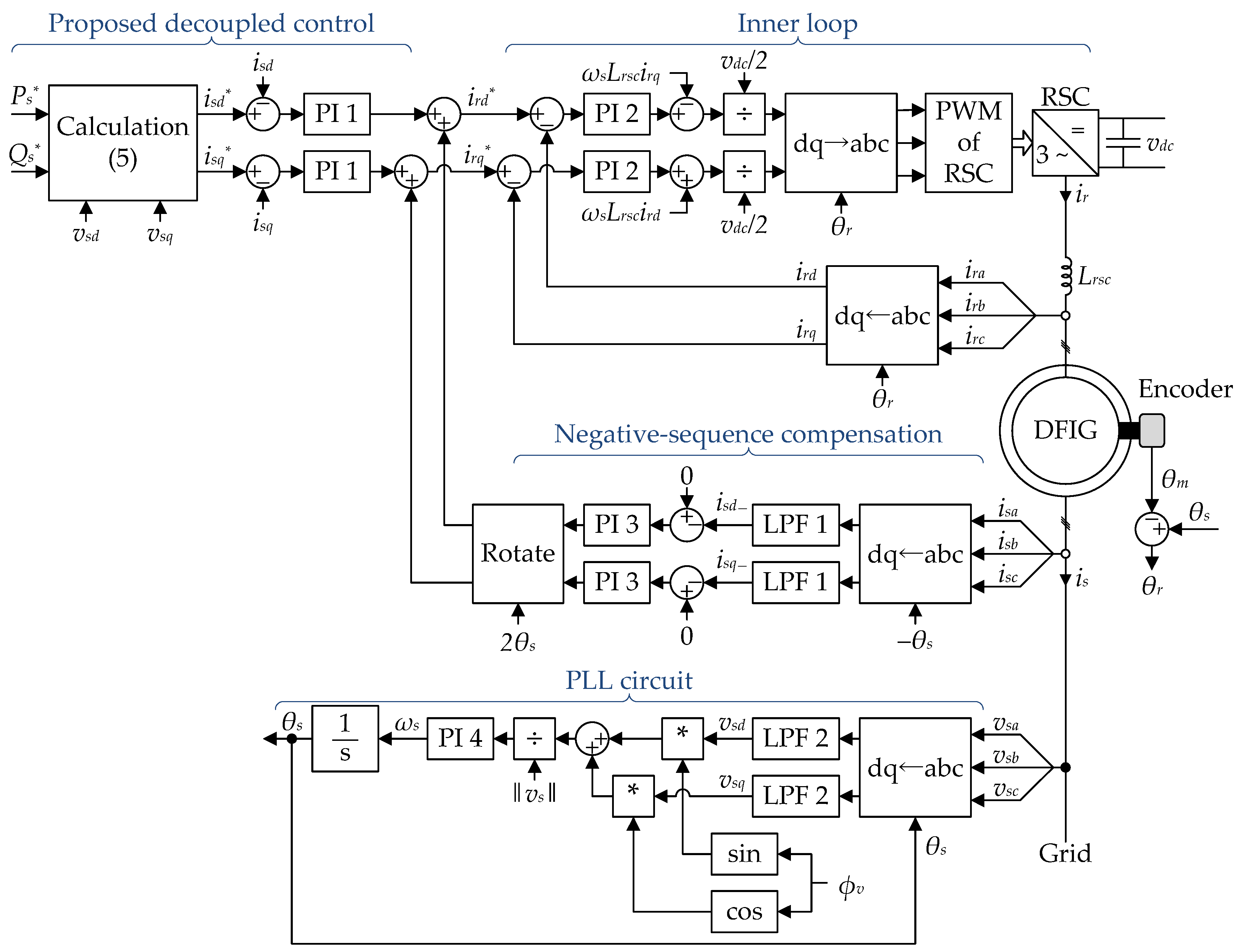
3. Proposed Decoupled Control

3.1. Concept

By mathematical manipulation, Equation (1) can be used to calculate the stator d- and q-currents from the active and reactive powers as follows:
Multiplying the active power by vsd and the reactive power by vsq we get:
{ v sd P s = i sd v sd 2 + i sq v sd v sq v sq Q s = i sd v sq 2 i sq v sd v sq
By adding these two equations we get:
i sd ( v sd 2 + v sq 2 ) = v sd P s + v sq Q s
Then, multiplying the active power by vsq and the reactive power by −vsd we get:
{ v sq P s = i sd v sd v sq + i sq v sq 2 v sd Q s = i sd v sd v sq + i sq v sd 2
By adding these two equations we get:
i sq ( v sd 2 + v sq 2 ) = v sq P s v sd Q s
From Equations (6) and (8), the stator d- and q-current references can be calculated from the active and reactive power references using Equation (9) which is independent of the DFIG parameters.
{ i sd * = v sd P s * + v sq Q s * v sd 2 + v sq 2 i sq * = v sq P s * v sd Q s * v sd 2 + v sq 2
The stator d- and q-current, in Equation (4), are normally decoupled, and they can be controlled by the rotor d- and q-current respectively. The stator voltage is supplied from the grid and can be considered constant; then, the simplified DFIG model can be given by:
{ i rd N s N r i sd i rq N s N r i sq
Since the DFIG model in Equation (10) is linear, the rotor current references can be generated from the stator currents using PI controllers. The block diagram of the proposed decoupled control is depicted in Figure 4.
Although the DFIG model in Equation (10) is an approximation of the actual DFIG model which introduces some model inaccuracy, the steady-state response is not affected due to the integrator action of the PI controllers which compensates any steady-state error. To reduce the effect of the DFIG dynamics on the transient response, the bandwidth of the decoupled control should be smaller than the DFIG poles.
The proposed decoupled control does not require forcing the stator q-voltage to zero; this gives the proposed control more flexibility and robustness compared with the conventional decoupled P-Q control. Moreover, the online calculations of the proposed decoupled control does not require any DFIG parameter.

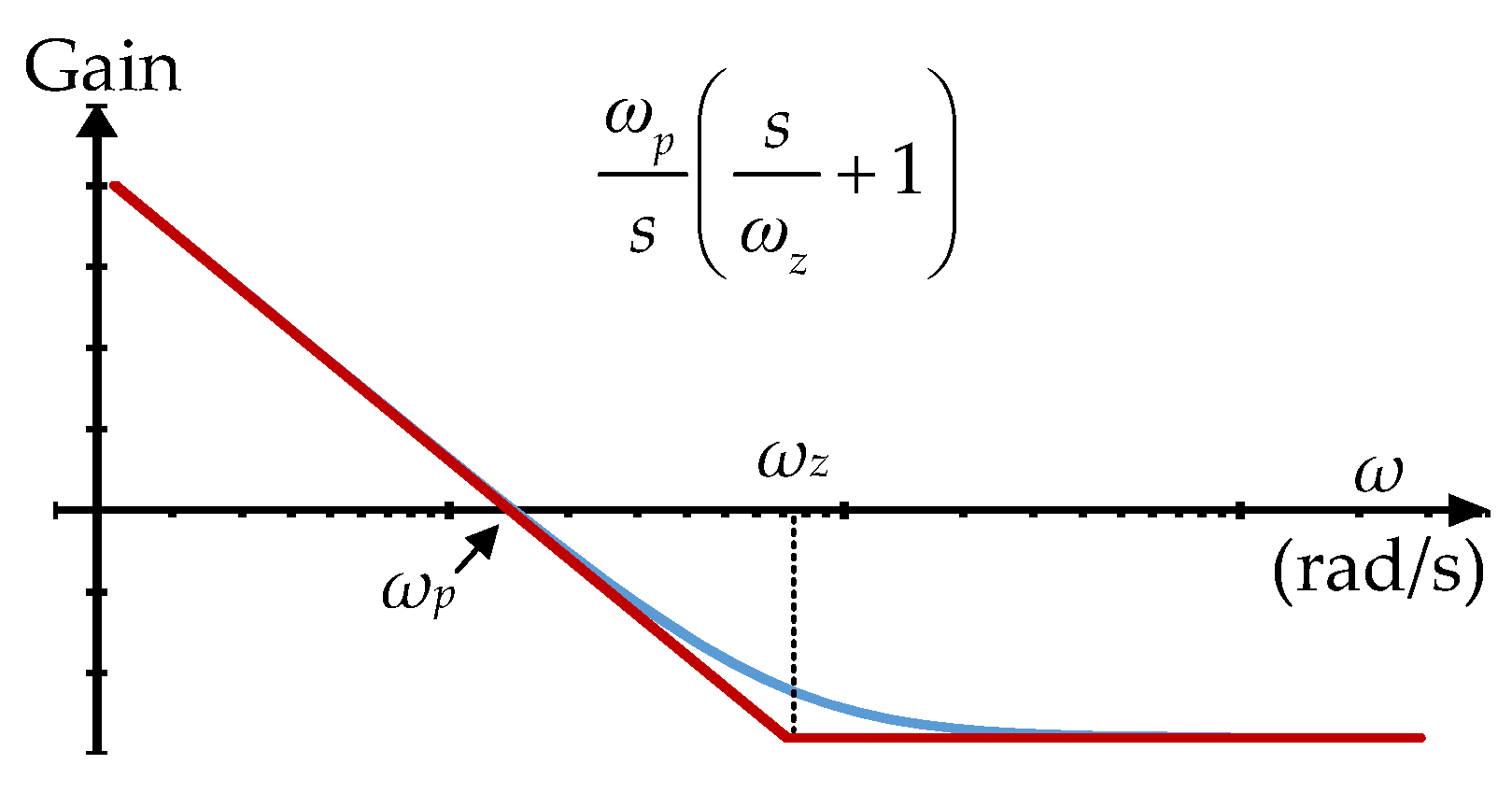
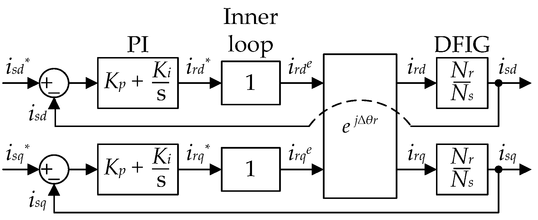
3.2. Controller Design

Since the rotor current loop, which is also referred to as the inner loop, is much faster than the decoupled control, the inner loop can be approximated by a unity gain. The DFIG’s poorly damped poles near the line frequency [32,33] can be ignored if the decoupled control’s bandwidth is smaller than the line frequency, and the DFIG model can be approximated by Equation (10). The simplified control model of the proposed decoupled control is shown in Figure 5.
The simplified open-loop transfer function of the active component is given by Equation (11), and its Bode diagram is depicted in Figure 6.
i sd i sd * i sd = ω p s ( s ω z + 1 ) where { ω p = N r N s K i ω z = K i K p
Referring to Figure 6, the transfer function has a pole whose gain is ωp, and a zero at ωz. The frequency ωp, which is equal to the bandwidth, must be smaller than the line frequency to reduce the effect of the DFIG’s poorly damped poles. The frequency ωz must be located at a higher frequency than ωp to achieve adequate attenuation of high frequency noise; consequently, the proportional gain must be smaller than the stator-to-rotor turns ratio, Kp < Ns/Nr. In this paper, the frequency ωp is selected five times smaller than the line frequency, and ωp is selected around 12 times smaller than the frequency ωz.
The controller design and the transient response of the proposed decoupled control are dependent on the stator-to-rotor turns ratio, which is slightly affected by saturation and can be considered constant up to about 120% of the rated stator flux [34] which is normally the case. Thus, the proposed decoupled control can be considered independent of variations in the DFIG parameters.

3.3. Sensitivity to Slip Angle Inaccuracy
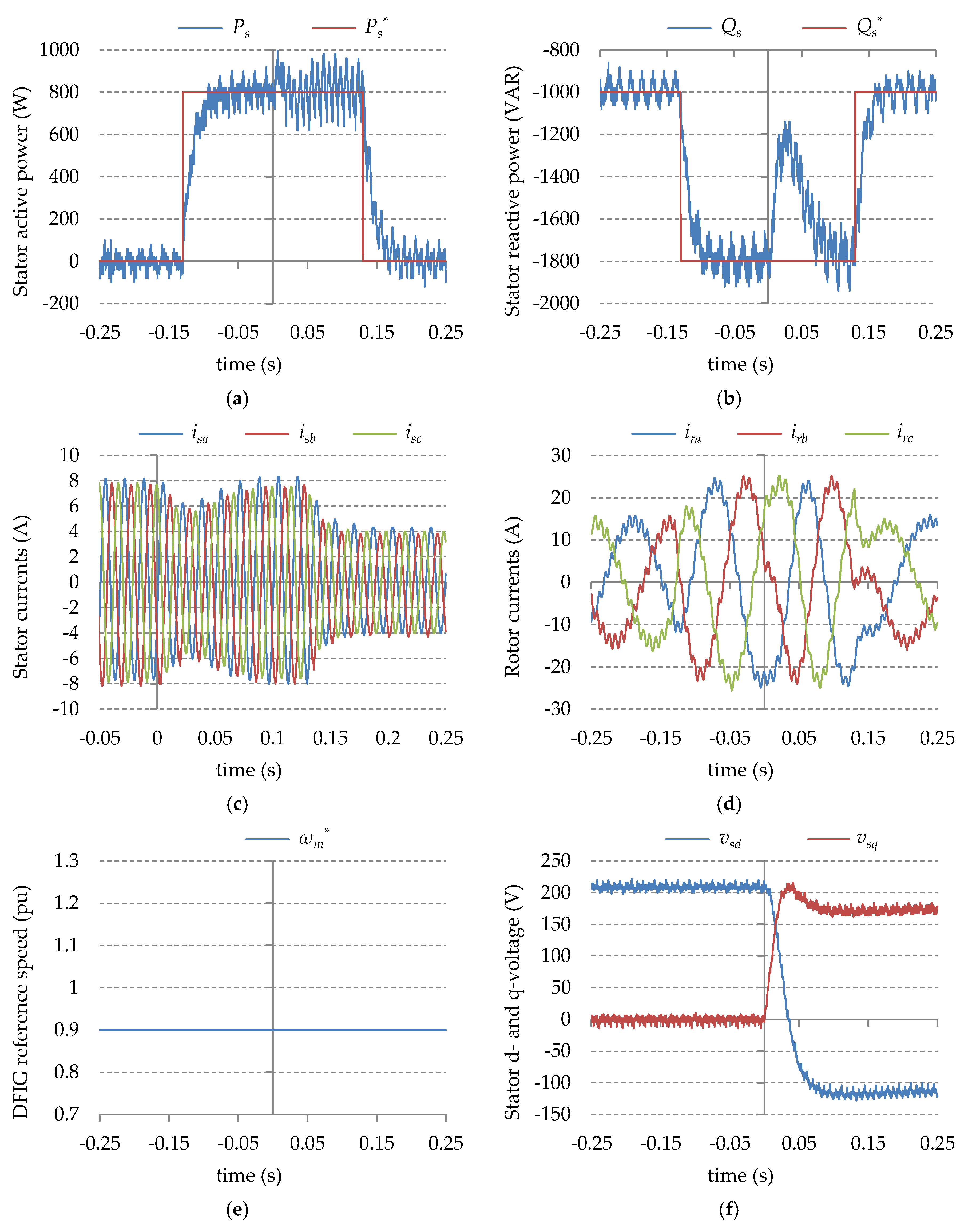
The measurement or the estimation of the DFIG’s rotor position, which is used to obtain the slip angle, will always contain a certain amount of error especially in the case of software estimators due to inaccuracy in their mathematical model. Thus, it is important to investigate the effect of inaccuracy in the slip angle on the performance of the proposed decoupled control.
In the decoupled control, the slip angle is used to express the rotor quantities in the dq-frame. Let’s assume that this slip angle, which is referred to as θre, contains an error Δθr as in:
θ r e = θ r + Δ θ r
The dq-transformation of the rotor current using θre, which is referred to as ire, is related to the correct dq-transformation of the rotor current by:
( i rd e i rq e ) = ( cos ( Δ θ r ) sin ( Δ θ r ) sin ( Δ θ r ) cos ( Δ θ r ) ) ( i rd i rq )
By introducing Equation (13) into Figure 5, the control model of the proposed decoupled control with a slip angle error is obtained and is depicted in Figure 7.
If the transfer functions of the PI controller, the inner loop, and the DFIG are combined in one transfer function which is denoted by G, the closed-loop transfer function of the proposed decoupled control is given by:
( i sd i sq ) = ( G 2 + G cos ( Δ θ r ) G sin ( Δ θ r ) G sin ( Δ θ r ) G 2 + G cos ( Δ θ r ) ) G 2 + 2 G cos ( Δ θ r ) + 1 ( i sd * i sq * )
The characteristic equation of Equation (14) is given by:
G 2 + 2 G cos ( Δ θ r ) + 1 = 0
Substituting the transfer function of the PI controller and the simplified DFIG model into Equation (15), the characteristic equation is given by Equation (16) where “a” is the stator-to-rotor turns ratio (a = Ns/Nr).
( K p 2 + 2 a K p cos ( Δ θ r ) + a 2 ) s 2 + 2 K i ( K p + a cos ( Δ θ r ) ) s + K i 2 = 0
The slip angle error at which the decoupled control is stable can be obtained by applying the Routh-Hurwitz stability criterion to Equation (16). This produces two stability conditions which are given by:
cos ( Δ θ r ) > ( K p 2 + a 2 ) 2 a K p
cos ( Δ θ r ) > K p a
The condition in Equation (17) can be easily proved to be always true. Thus, the stability is determined by the condition in Equation (18), and the stable range is given by:
cos 1 ( K p a ) < Δ θ r < cos 1 ( K p a )
Since the proportional gain (Kp) is smaller than the DFIG’s turns ratio, the stable range is slightly above ±90 degrees which shows that the proposed decoupled control can tolerate large error in the slip angle; this robustness is owing to the existence of PI controllers in the outer loop (the decoupled control). On the other hand, the direct control strategies do not have PI controllers and require knowledge of the sector in which the rotor flux is located in order to select the appropriate switching voltage vectors [2]. A large error in the slip angle would result in an incorrect identification of the sector and, consequently, a faulty selection of the switching vector. To our knowledge, in the literature, there is no sensitivity analysis of the direct control strategies, but the sector can be correctly identified as long as the slip angle error is below ±30 degrees.

4. Results

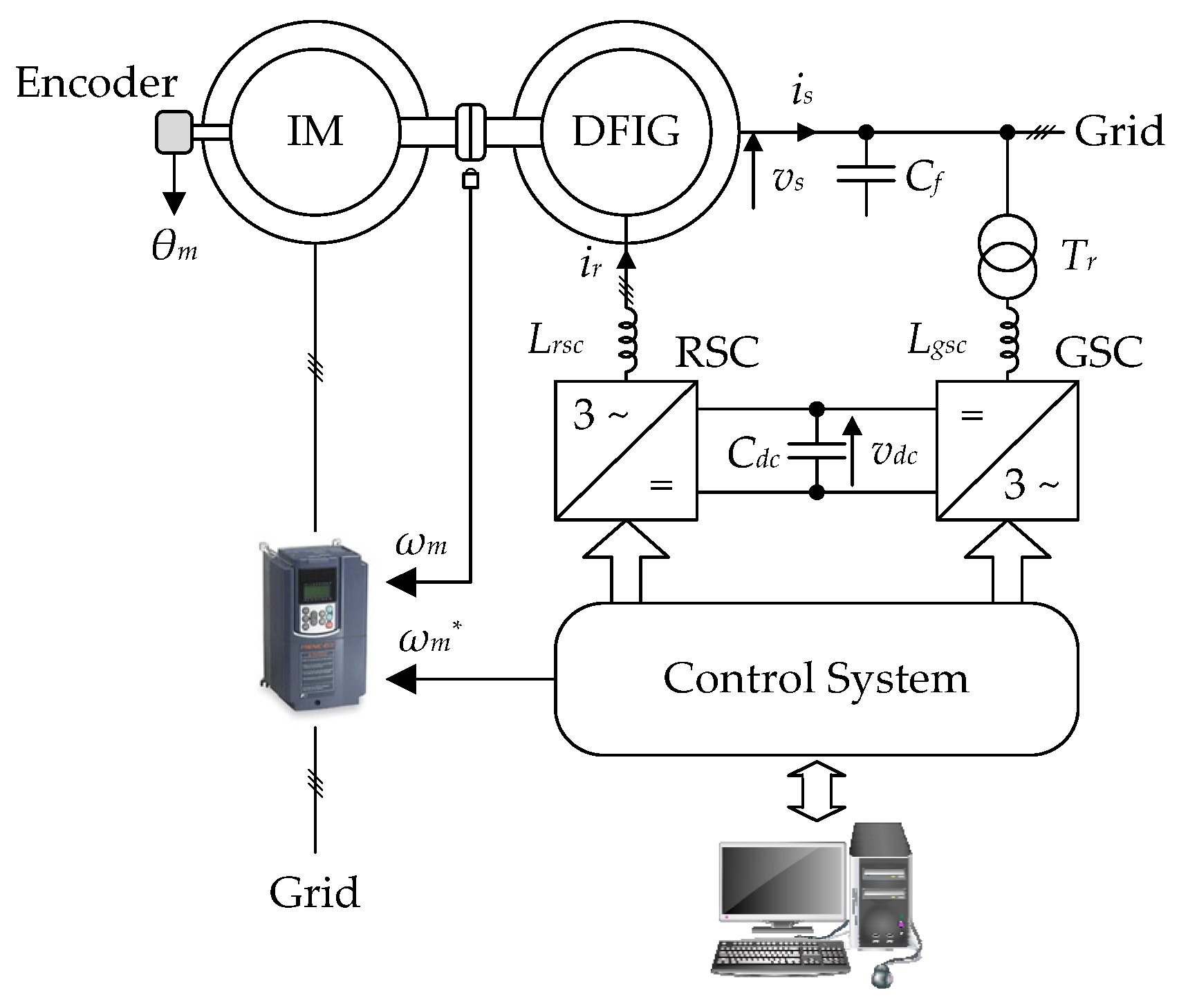
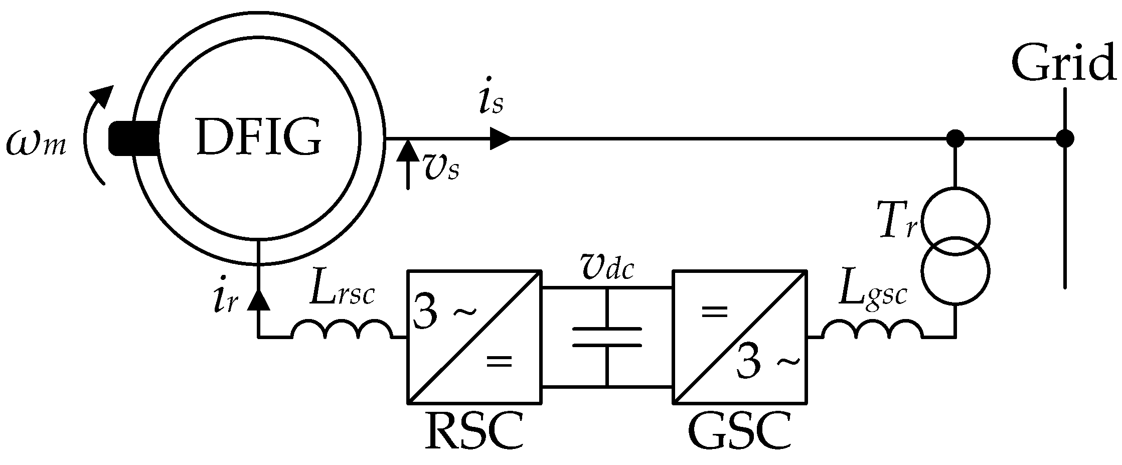
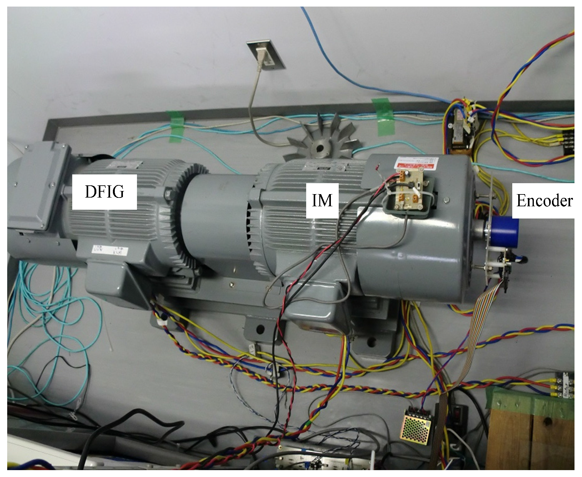
4.1. Experimental Setup

The experimental setup is shown in Figure 8. A 1.1 kW DFIG, whose parameters are listed in Table 1, is rotated by a three-phase induction machine which is driven by a commercial, three-phase inverter operating in speed control mode. The parameters of the DFIG’s circuit are listed in Table 2, and a photo of the experimental rig is shown in Figure 9.
A commercial, DSP-based, digital control system is used to implement the control system. The schematic diagram of the complete control system of the rotor side converter, which is referred to as RSC, is shown in Figure 10.
The PLL circuit in Figure 10 can control the voltage orientation by adjusting the angle φv, which is referred to as the orientation angle. The concept of the PLL circuit is derived from the dq-transformation of the stator (grid) voltage. For the stator voltage which is defined by Equation (20), the dq-transformation using the angle θs is given by Equation (21).
( v sa v sb v sc ) = 2 3 v s ( cos ( θ g ) cos ( θ g 2 π 3 ) cos ( θ g + 2 π 3 ) ) , where θ g = ω g t
( v s ) dq = ( v sd v sq ) = v s ( cos ( θ g θ s ) sin ( θ g θ s ) )
Using the properties of the trigonometric identities, the following equation is obtained.
v sd sin ( φ v ) + v sq cos ( φ v ) v s = sin ( θ g θ s + φ v )
Equation (22) is fed to a PI controller followed by an integrator which force this equation to zero by generating the synchronous angle which is given by Equation (23). The orientation angle is normally set to zero to obtain the grid voltage angle except when otherwise declared.
θ s = θ g + φ v
The slip angle θr is obtained by subtracting the DFIG’s rotor angle θm which is measured by the mechanical encoder from the synchronous angle θs which is obtained by the PLL circuit. The control system contains a negative-sequence compensation to eliminate the stator negative-sequence current. The low pass filter, LPF 1, in the negative-sequence compensation is composed of two cascaded first order low pass filters. The parameters of the control system are listed in Table 3.

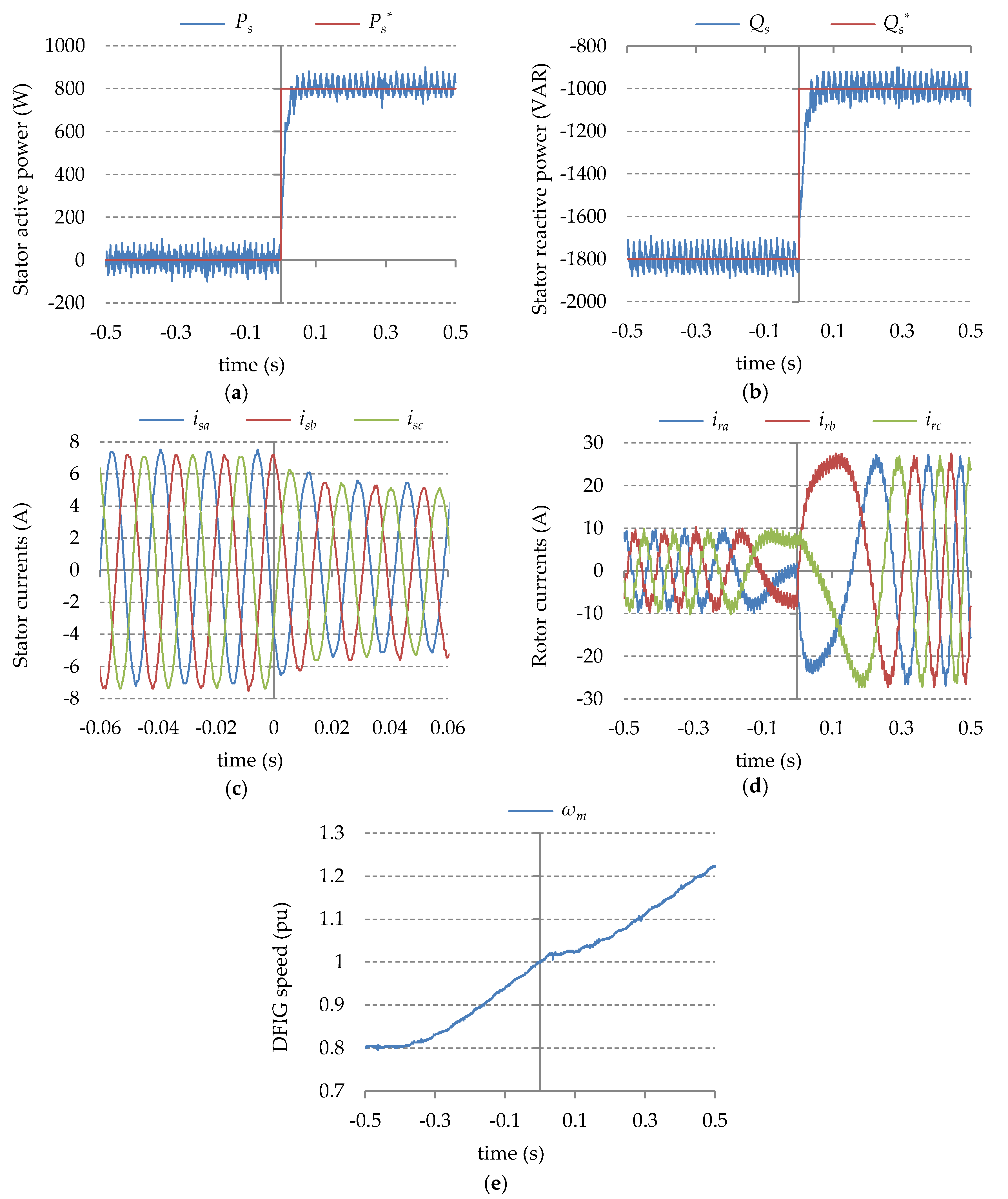
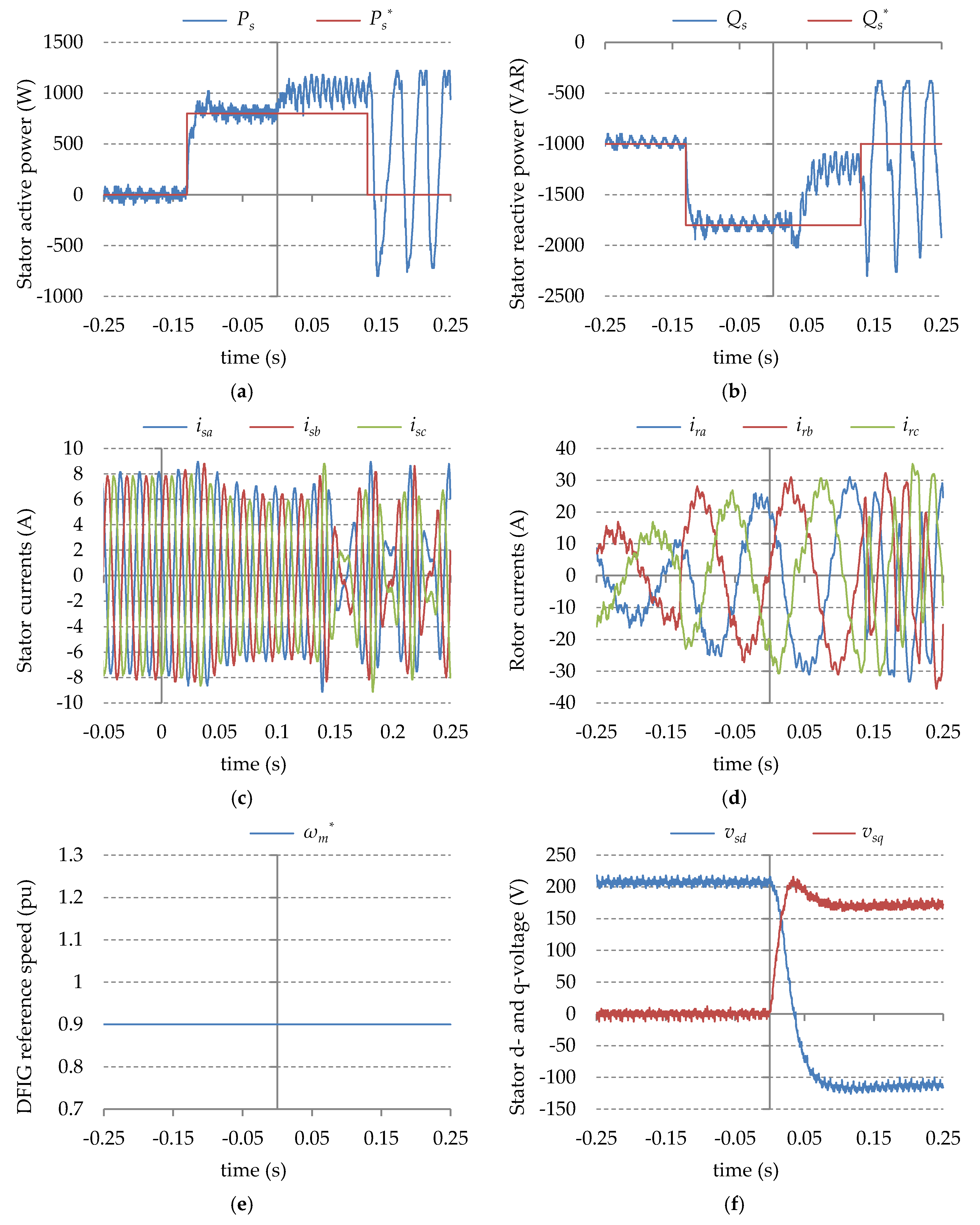
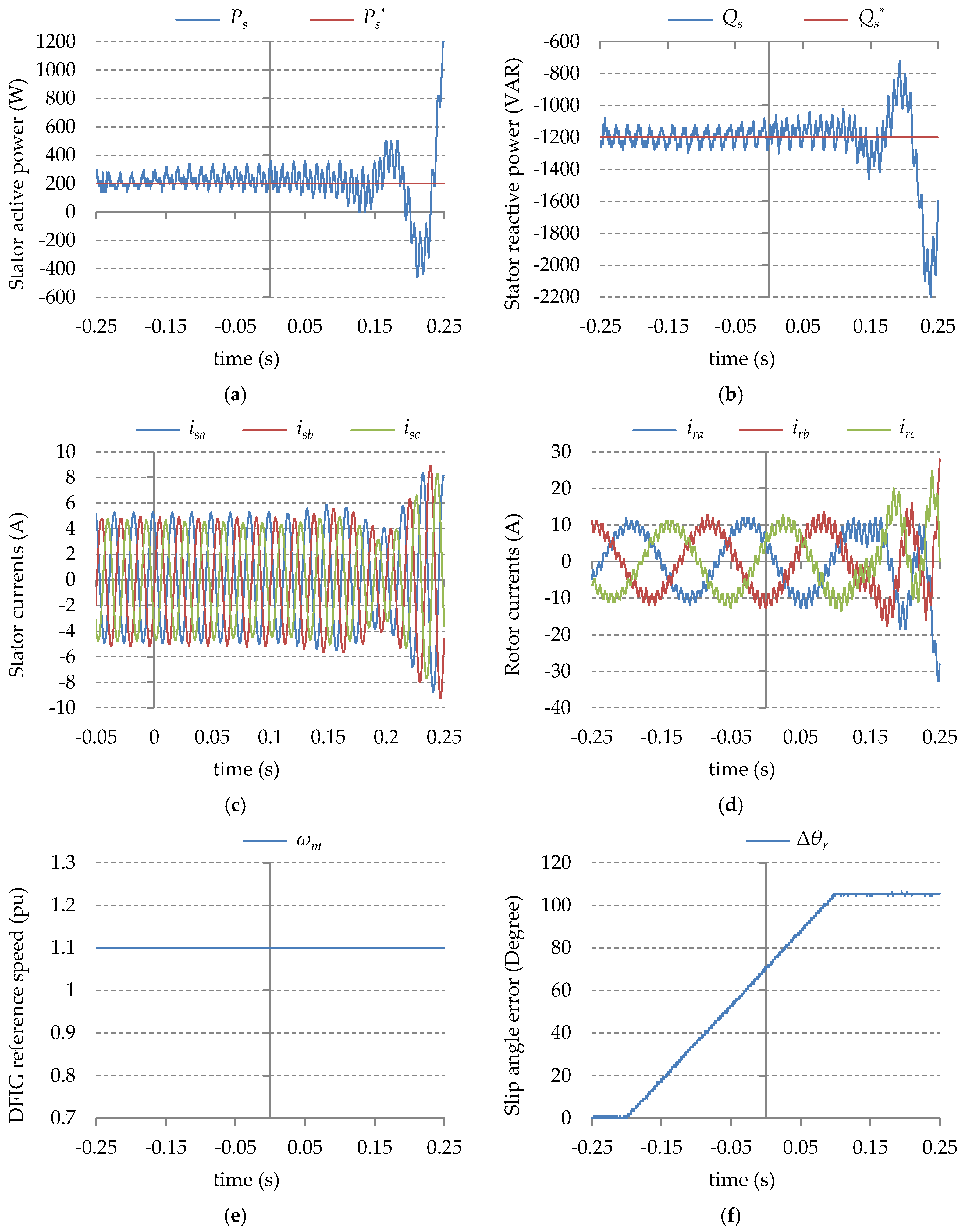
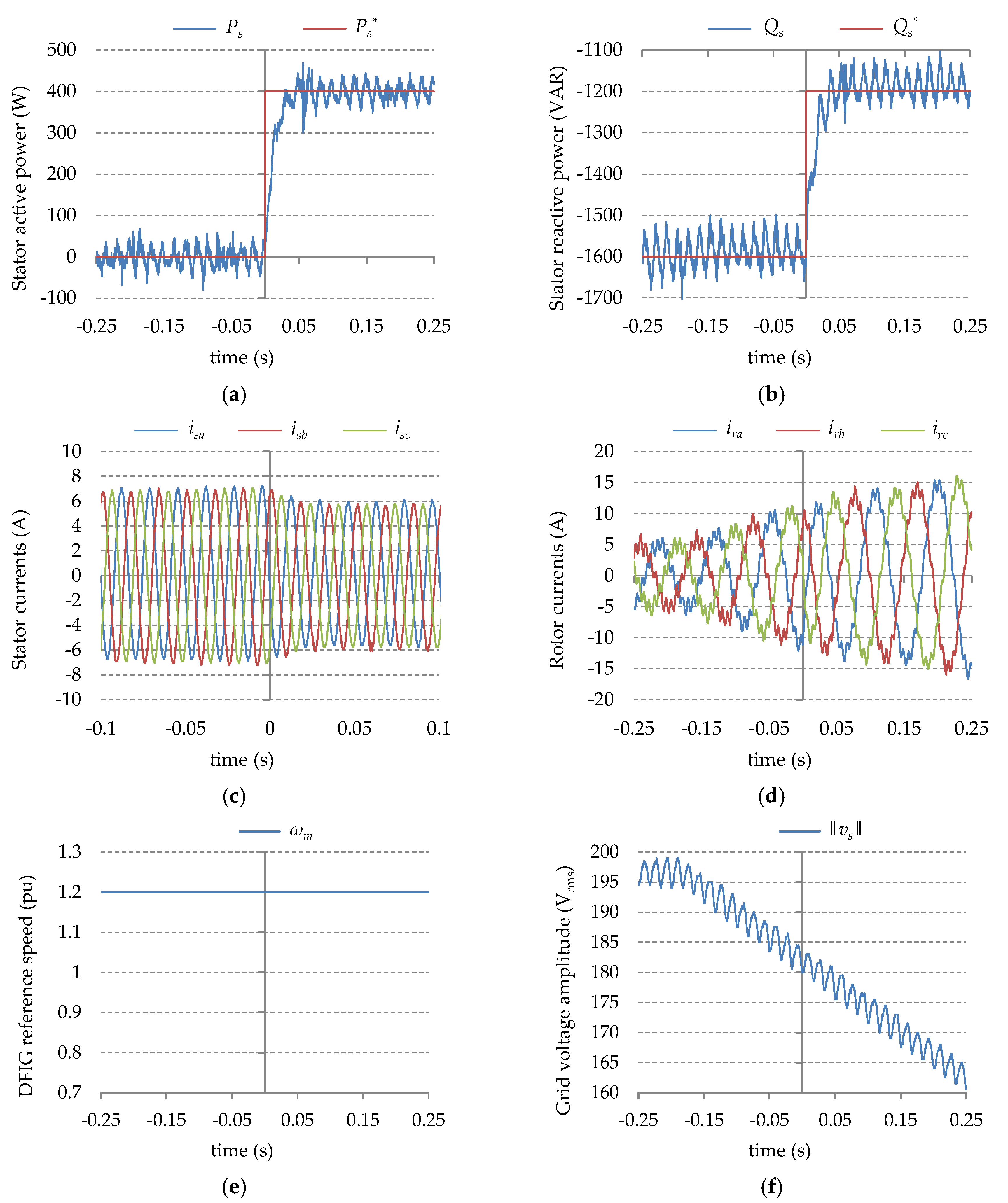
4.2. Experimental Results

First, the variable speed operation is investigated. The DFIG speed is varied from a sub-synchronous speed of 0.8 pu to a hyper-synchronous speed of 1.2 pu within 1 s. At 0 s, the active and reactive power references are stepped from 0 W to 800 W and from −1800 VAR to −1000 VAR respectively. The results for this test are shown in Figure 11.
The proposed decoupled control effectively regulates the stator active and reactive powers regardless of the DFIG’s speed variation. Thus, the proposed control is suitable for variable speed generation systems such as wind turbines. In addition, the responses of the active and reactive powers have good dynamics with settling time of around 50 ms.
Second, the effect of variation of the grid voltage orientation is investigated. Two experiments are carried out: In the first experiment, the conventional decoupled P-Q control is employed and, in the second, the proposed decoupled control is employed. The PI parameters of the conventional decoupled method are selected to have the same transfer function as the proposed decoupled control. Initially, the orientation angle is equal to zero then, at 0 s, it is set to −120 degrees. The results for this test with the conventional method are shown in Figure 12, and for the proposed method is shown in Figure 13.
From the results in Figure 12, it is clear that the dynamics and stability of the conventional decoupled control is dependent on the grid voltage orientation. For an orientation error of −120 degrees, the conventional method loses controllability of the active and reactive powers.
On the other hand, it is clear, from the results in Figure 13 that the stability and the performance of the proposed decoupled control is independent of the stator voltage orientation except for a short transition in the responses of the active and reactive powers due to the sudden change of the orientation of the magnetizing current (vssLm). There is also a small and slowly decaying oscillation of the active power which has resulted from the slow transient response of the negative-sequence compensation. These results demonstrate the flexibility and robustness of the proposed decoupled control.
Next, the effect of the slip angle error on the proposed decoupled control is investigated. In this test, the DFIG reference speed is fixed at a hyper-synchronous speed of 1.1 pu, and the active and reactive power references are fixed at 200 W and −1200 VAR respectively. The error Δθr is increased linearly from zero up to around 105 degrees. The results for this test are given in Figure 14.
From the results of Figure 14, the proposed decoupled control can tolerate large inaccuracy in the slip angle before the active and reactive powers become unstable; this demonstrates the robustness of the proposed decoupled control against slip angle errors.
By substituting the circuit parameters into Equation (19), the unstable slip angle error is found to be around ± 94.5 degrees. The practical value is, however, slightly smaller due to the effect of the inner loop and the DFIG’s poorly damped poles which were ignored when deriving Equation (19).
Finally, the proposed decoupled control is tested under grid voltage variation. Using a programmable AC source, the grid voltage amplitude reference is linearly decreased from 200 V to 160 V within 0.5 s, while the DFIG speed is fixed at a hyper-synchronous speed of 1.2 pu. The grid voltage is polluted with a small negative-sequence component of around 1% of the rated voltage. During this test, the active and reactive power references are stepped from 0 W to 400 W and from −1600 VAR to −1200 VAR respectively. The results for this test are shown in Figure 15.
From Figure 15, the performance of the proposed decoupled control is not affected by the variation of the grid voltage which makes the proposed decoupled control suitable for distributed generation systems and remote wind turbines or weak grids. Since AC machines operate at the knee of the saturation curve [34], the variation of the grid voltage amplitude is associated with variation of some DFIG’s parameters, especially the magnetizing inductance. Consequently, the results in Figure 15 also demonstrate the robustness of the proposed decoupled control against variations in the DFIG’s parameters due to saturation.

5. Discussion

The experimental results demonstrated several advantages of the proposed decoupled control. The proposed decoupled control has all the advantages of the conventional decoupled P-Q control: The proposed decoupled control is robust against variation in the DFIG’s speed, and it can achieve relatively fast response of the active and reactive powers. This makes the proposed decoupled control suitable for variable speed generation systems. The proposed decoupled control is robust against large inaccuracy in the slip angle; thus, it is suitable for sensorless control which is achieved by employing a slip angle estimator.
The proposed decoupled control has additional advantages which were investigated experimentally: the performance of the proposed decoupled control is independent of the stator voltage amplitude and orientation. Since the variation of grid voltage amplitude is associated with variation of some DFIG parameters, it can be concluded that the proposed decoupled control is robust against parameter variation due to saturation. Thus, the proposed decoupled control is suitable for distributed generation systems and weak grids.
As for future research, the performance of the proposed decoupled control under different grid disturbances must be investigated. In addition, the performance of the proposed decoupled control should be compared with the direct control methods experimentally, and the sensitivity analysis of the direct control methods against inaccuracy in the slip angle should be carried out.

6. Conclusions

In this paper a new decoupled control, which is based on decoupling the stator active and reactive currents, was proposed. The proposed decoupled control has all the advantages of the conventional decoupled P-Q control such as constant switching frequency, low power ripples compared with direct control methods, and robustness against slip angle inaccuracy. It also has additional advantages: The proposed method is independent of the grid voltage orientation and amplitude. The proposed method does not require any DFIG parameter for the online calculations while the conventional method requires two (Lm and the DFIG’s turns ratio). The dynamics of the proposed method depend on the DFIG’s turns ratio which can be considered constant, while the dynamics of the conventional method depend on the grid voltage amplitude; this makes the proposed method more suitable for modern, variable speed, distributed generation systems such as wind turbines, and natural gas engine-based generation systems. The proposed decoupled control is a viable alternative for the conventional decoupled P-Q control.

Author Contributions

Ahmad Bashar Ataji conceived the proposed control strategy, performed the experiments, participated in analyzing the data, and wrote the paper. Yushi Miura provided guidance and key suggestions and helped in some experiments. Toshifumi Ise provided guidance and key suggestions, participated in analyzing the data, and helped in writing the paper. Hiroki Tanaka provided guidance and key suggestions.

Conflicts of Interest

The authors declare no conflict of interest.

Nomenclature

ψs and ψrStator and rotor flux linkages
ωs and ωrSynchronous and slip angular frequency (rad/s)
ωmDFIG’s rotor speed (pu)
Ls and LrDFIG’s stator and rotor inductances
Lσs and LσrDFIG’s stator and rotor leakage inductances
LmMutual inductance between the DFIG’s stator and the rotor
Rs and RrDFIG’s stator and rotor winding resistances
Ns and NrDFIG’s stator and rotor number of winding’s turns
( )dqRepresentation in the synchronous reference frame

References

  1. Jafarnejadsanil, H.; Pieper, J. Gain-scheduled l1-optimal control of variable-speed-variable-pitch wind turbines. IEEE Trans. Control Syst. Technol. 2015, 23, 372–379. [Google Scholar] [CrossRef]
  2. Singh, B.; Naidu, N.K.S. Direct power control of single VSC-based DFIG without rotor position sensor. IEEE Trans. Ind. Appl. 2014, 50, 4152–4163. [Google Scholar] [CrossRef]
  3. Pena, R.; Cardenas, R.; Proboste, J.; Clare, J.; Asher, G. Wind-diesel generation using doubly fed induction machines. IEEE Trans. Energy Convers. 2008, 23, 202–214. [Google Scholar] [CrossRef]
  4. Cardenas, R.; Clare, J.; Wheeler, P. 4-leg matrix converter interface for a variable-speed diesel generation system. In Proceedings of the 38th Annual Conference on IEEE Industrial Electronics Society, Montreal, QC, Canada, 25–28 October 2012.
  5. Iwanski, G.; Koczara, W. Power management in an autonomous adjustable speed large power diesel gensets. In Proceedings of the 13th Power Electronics and Motion Control Conference, Poznan, Poland, 1–3 September 2008.
  6. Fraile-Ardanuy, J.; Wilhelmi, J.R.; Fraile-Mora, J.J.; Perez, J.I. Variable-speed hydro generation: Operational aspects and control. IEEE Trans. Energy Convers. 2006, 21, 569–574. [Google Scholar] [CrossRef]
  7. Belhadji, L.; Bacha, S.; Munteanu, I.; Rumeau, A.; Roye, D. Adaptive MPPT applied to variable-speed microhydropower plant. IEEE Trans. Energy Convers. 2013, 28, 34–43. [Google Scholar] [CrossRef]
  8. Kanjiya, P.; Ambati, B.B.; Khadkikar, V. A novel fault-tolerant DFIG-based wind energy convers. System for seamless operation during grid faults. IEEE Trans. Power Syst. 2014, 29, 1296–1305. [Google Scholar] [CrossRef]
  9. Reigosa, D.D.; Briz, F.; Blanco, C.; Guerrero, J.M. Sensorless control of doubly fed induction generators based on stator high-frequency signal injection. IEEE Trans. Ind. Appl. 2014, 50, 3382–3391. [Google Scholar] [CrossRef]
  10. Nian, H.; Song, Y. Direct power control of doubly fed induction generator under distorted grid voltage. IEEE Trans. Power Electron. 2014, 29, 894–905. [Google Scholar] [CrossRef]
  11. Pena, R.; Clare, J.C.; Asher, G.M. Doubly fed induction generator using back-to-back PWM Converters and its Application to Variable-Speed Wind-Energy Generation. IEE Proc. Electric Power Appl. 1996, 143, 231–241. [Google Scholar] [CrossRef]
  12. Datta, R.; Ranganathan, V.T. Decoupled control of active and reactive power for a grid-connected doubly-fed wound rotor induction machine without position sensors. In Proceeding of the IEEE/IAS Annual Meeting, Phoenix, AZ, USA, 3–7 October 1999.
  13. Datta, R.; Ranganathan, V.T. A simple position-sensorless algorithm for rotor-side field-oriented control of wound-rotor induction machine. IEEE Trans. Ind. Electron. 2001, 48, 786–793. [Google Scholar] [CrossRef]
  14. Arnalite, S.; Burgos, J.C.; Rodriguez-Amendo, J.L. Direct torque control of a doubly-fed induction generator for variable speed wind turbines. Electric Power Compon. Syst. 2002, 30, 199–216. [Google Scholar] [CrossRef]
  15. Mahi, Z.; Serban, C.; Siguerdidjane, H. Direct torque control of a doubly-fed induction generator of a variable speed wind turbine power regulation. In Proceeding of the European Wind Energy Conference, Milan, Italy, 7–10 May 2007.
  16. Datta, R.; Ranganathan, V.T. Direct power control of grid-connected wound rotor induction machine without rotor position sensors. IEEE Trans. Power Electron. 2001, 16, 390–399. [Google Scholar] [CrossRef]
  17. Xu, L.; Cartwright, P. Direct active and reactive power control of dfig for wind energy generation. IEEE Trans. Energy Convers. 2006, 21, 750–758. [Google Scholar] [CrossRef]
  18. Zhi, D.; Xu, L.; Williams, B.W. Model-based predictive direct power control of doubly fed induction generators. IEEE Trans. Power Electron. 2010, 25, 341–351. [Google Scholar]
  19. Chen, S.Z.; Cheung, N.C.; Wong, K.C.; Wu, J. Integral sliding-mode direct torque control of doubly-fed induction generators under unbalanced grid voltage. IEEE Trans. Energy Convers. 2010, 25, 356–368. [Google Scholar] [CrossRef]
  20. Abad, G.; Rodriguez, M.A.; Poza, J. Two-level VSC based predictive direct torque control of the doubly fed induction machine with reduced torque and flux ripples at low constant switching frequency. IEEE Trans. Power Electron. 2008, 23, 1050–1061. [Google Scholar] [CrossRef]
  21. Abad, G.; Rodriguez, M.A.; Poza, J. Two-level VSC-based predictive direct power control of the doubly fed induction machine with reduced power ripple at low constant switching frequency. IEEE Trans. Energy Convers. 2008, 23, 570–580. [Google Scholar] [CrossRef]
  22. Filho, A.J.S.; Filho, E.R. Model-Based Predictive Control Applied to the Doubly-Fed Induction Generator Direct Power Control. IEEE Trans. Sustain. Energy 2012, 3, 398–406. [Google Scholar] [CrossRef]
  23. Mwinyiwiwa, B.; Zhang, Y.; Shen, B.; Ooi, B.T. Rotor position phase-locked loop for decoupled P-Q control of DFIG for wind power generation. IEEE Trans. Energy Convers. 2009, 24, 758–765. [Google Scholar] [CrossRef]
  24. Karthikeyan, A.; Nagamani, C.; Ilango, G.S. A versatile rotor position computation algorithm for the power control of a grid-connected doubly fed induction generator. IEEE Trans. Energy Convers. 2012, 27, 697–706. [Google Scholar] [CrossRef]
  25. Li, S.; Haskew, T.A.; Williams, K.A.; Swatloski, R.P. Control of DFIG wind turbine with direct-current vector control configuration. IEEE Trans. Sustain. Energy 2012, 3, 1–11. [Google Scholar] [CrossRef]
  26. Pena, R.; Cárdenas, R.; Proboste, J.; Asher, G.; Clare, J. Sensorless control of doubly-fed induction generators using a rotor-current based MRAS observer. IEEE Trans. Ind. Electron. 2008, 55, 330–339. [Google Scholar] [CrossRef]
  27. Shen, B.; Mwinyiwiwa, B.; Zhang, Y.; Ooi, B.T. Sensorless maximum power point tracking of wind by DFIG using rotor position phase locked loop (PLL). IEEE Trans. Power Electron. 2009, 24, 942–951. [Google Scholar] [CrossRef]
  28. Marques, G.D.; Sousa, D.M. New sensorless rotor position estimator of a DFIG based on torque calculations-stability study. IEEE Trans. Energy Convers. 2012, 27, 196–203. [Google Scholar] [CrossRef]
  29. Cárdenas, R.; Pena, R.; Clare, J.; Asher, G.; Proboste, J. MRAS observers for sensorless control of doubly-fed induction generators. IEEE Trans. Power Electron. 2008, 23, 1075–1084. [Google Scholar] [CrossRef]
  30. Prabhala, V.A.; Cespedes, M.; Sun, J. Implementation of DQ domain control in DSP and FPGA. In Proceedings of the 27th Annual IEEE Applied Power Electronics Conference and Exposition, Orlando, FL, USA, 5–9 February 2012.
  31. Ataji, A.B.; Miura, Y.; Ise, T.; Tanaka, H. Machine parameter independent control of a grid-connected variable speed doubly-fed induction generator for gas engine generation systems. In Proceedings of the IEEE ECCE Asia Downunder Conference, Melbourne, Australia, 3–6 June 2013.
  32. Petersson, A.; Harnefors, L.; Thiringer, T. Evaluation of current control methods for wind turbines using doubly-fed induction machines. IEEE Trans. Power Electron. 2005, 20, 227–235. [Google Scholar] [CrossRef]
  33. Morren, J.; De Haan, S.W.H. Ridethrough of wind turbines with doubly-fed induction generator during a voltage dip. IEEE Trans. Energy Convers. 2005, 20, 435–441. [Google Scholar] [CrossRef]
  34. Klaes, N.R. Parameter identification of an induction machine with regard to dependencies on saturation. IEEE Trans. Ind. Appl. 1993, 29, 1135–1140. [Google Scholar] [CrossRef]
Figure 1. Doubly-fed induction generator (DFIG)-based, variable speed, grid-connected generation system.
Energies 09 00179 g001
Figure 2. Equivalent circuit of the DFIG in the dq-frame.
Energies 09 00179 g002
Figure 3. Block diagram of the conventional decoupled Active and reactive powers (P-Q) control.
Energies 09 00179 g003
Figure 4. Block diagram of the proposed decoupled control.
Energies 09 00179 g004
Figure 5. Block diagram of the simplified control model of the proposed decoupled control.
Energies 09 00179 g005
Figure 6. Bode diagram of the open-loop transfer function of the proposed decoupled control.
Energies 09 00179 g006
Figure 7. Block diagram of the control model of the proposed decoupled control with slip angle error.
Energies 09 00179 g007
Figure 8. Schematic diagram of the experimental setup.
Energies 09 00179 g008
Figure 9. A photo of the experimental rig.
Energies 09 00179 g009
Figure 10. Block diagram of the control circuit for the rotor side converter (RSC) of the grid-connected DFIG.
Energies 09 00179 g010
Figure 11. Experimental results for variable speed operation (ωm = 0.8 pu → 1.2 pu): (a) stator active power; (b) stator reactive power; (c) stator currents; (d) rotor currents; (e) DFIG’s speed.
Energies 09 00179 g011
Figure 12. Experimental results for the effect of variation of the stator voltage orientation on the conventional decoupled P-Q control: (a) stator active power; (b) stator reactive power; (c) stator currents; (d) rotor currents; (e) DFIG’s reference speed; (f) stator (grid) d- and q-voltage.
Energies 09 00179 g012
Figure 13. Experimental results for the effect of variation of the stator voltage orientation on the proposed decoupled control: (a) stator active power; (b) stator reactive power; (c) stator currents; (d) rotor currents; (e) DFIG’s reference speed; (f) stator (grid) d- and q-voltage.
Energies 09 00179 g013
Figure 14. Experimental results for the effect of slip angle error on the proposed decoupled control: (a) stator active power; (b) stator reactive power; (c) stator currents; (d) rotor currents; (e) DFIG’s reference speed; (f) slip angle error.
Energies 09 00179 g014
Figure 15. Experimental results for the effect of variation of the grid voltage amplitude on the proposed decoupled control: (a) stator active power; (b) stator reactive power; (c) stator currents; (d) rotor currents; (e) DFIG’s reference speed; (f) stator (grid) voltage amplitude.
Energies 09 00179 g015
Table 1. Parameters of the DFIG.
ParameterValueParameterValue
Power rating1.1 kWStator rated voltage210 Vrms
Stator rated current6.3 ArmsRotor rated current20.3 Arms
Frequency60 HzNumber of poles6
Turns ratio Ns/Nr6.38Rs0.012 pu
Lσs and Lσr0.07 puLm0.67 pu
Table 2. Parameters of the DFIG’s circuit.
ParameterValueParameterValue
Grid voltage200 VrmsFrequency60 Hz
Lrsc4 mHLgsc6 mH
Turns ratio of Tr0.5Cf30 μF
Table 3. Parameters of the RSC’s control system.
BlockKpKiωcutoff(rad/s)
PI 10.5500-
PI 2201000-
PI 3540-
PI 450200-
LPF 1--12.5
LPF 2--500

