The operational principles of the conventional and proposed single-phase offline UPS systems are discussed below:
2.1. Conventional Single-Phase Offline UPS System
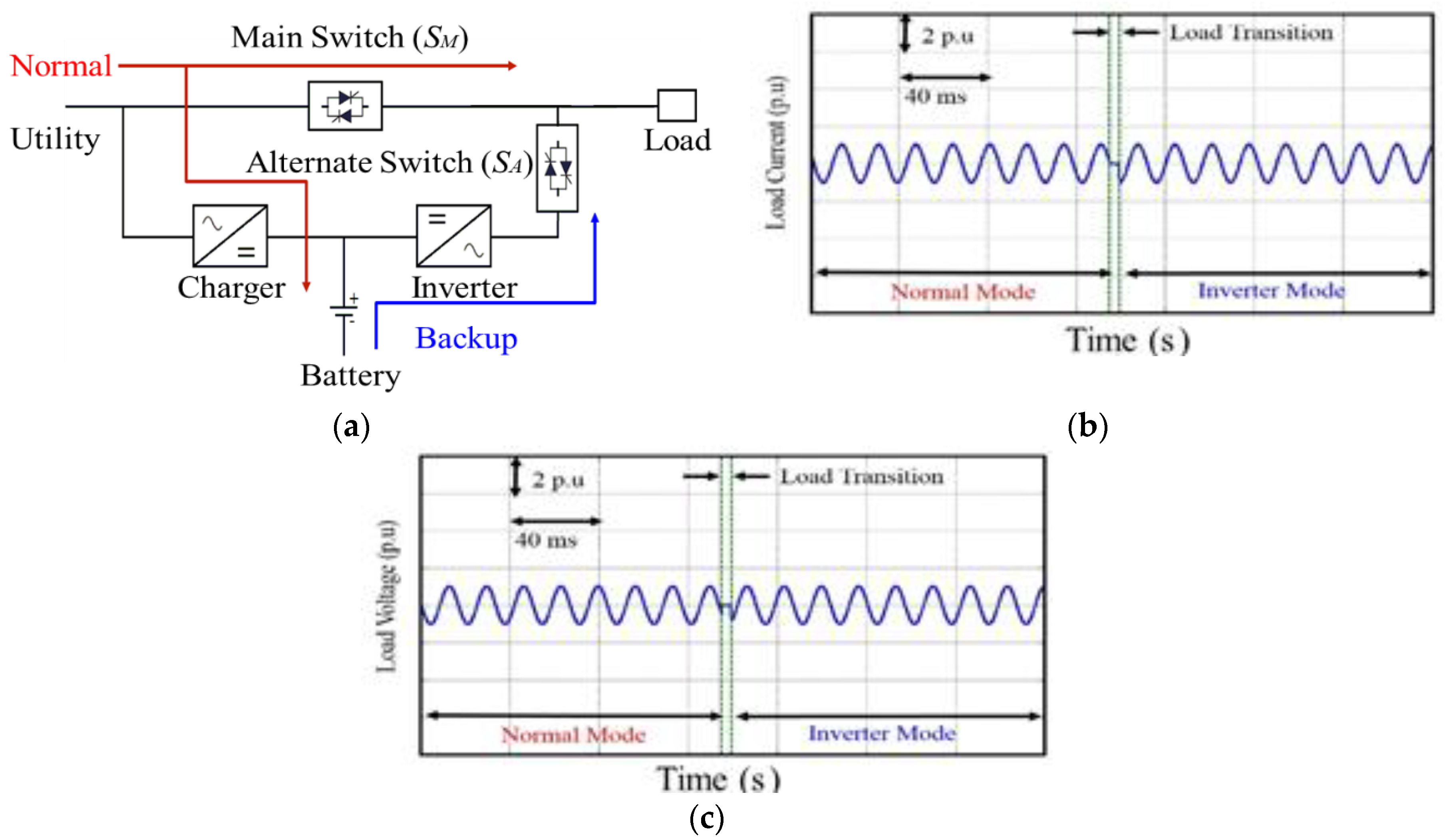
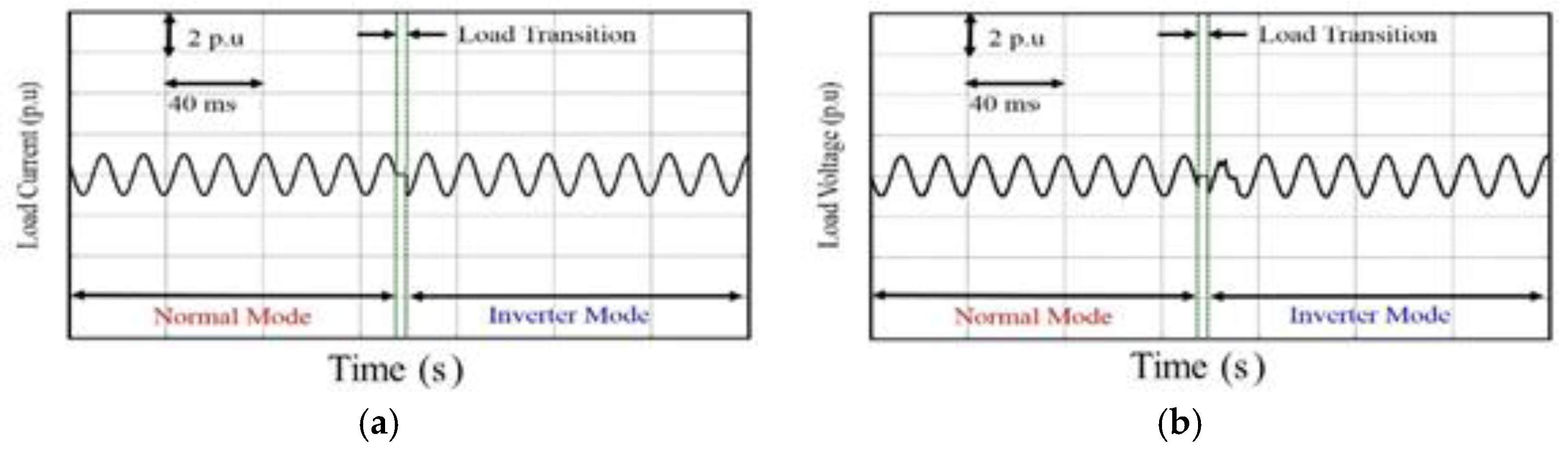
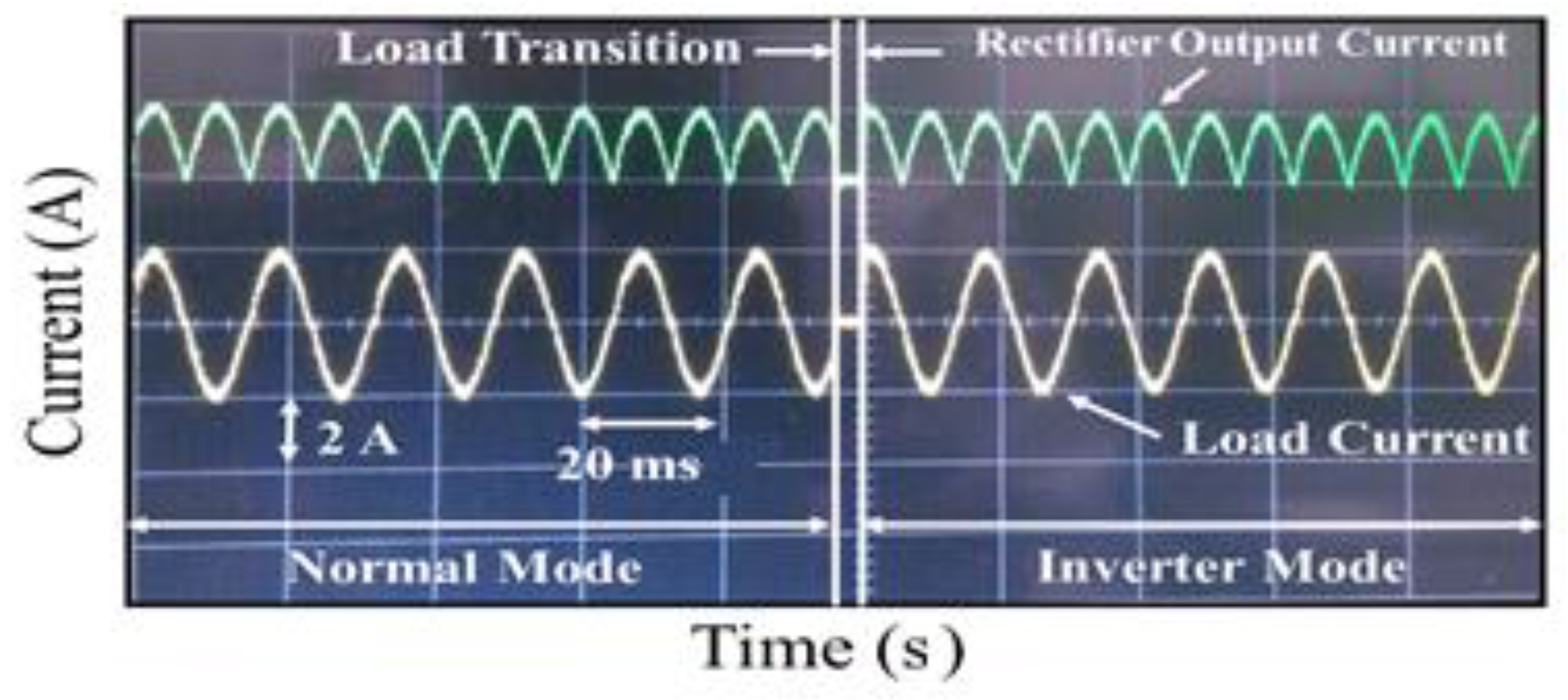
Figure 1a shows a basic diagram of an offline UPS system. During the normal utility power condition the inverter is bypassed by the main switch (
SM) and the load is delivered power directly by the utility without any isolation. Throughout this operation, the system is said to be in normal mode. Meanwhile, the battery is charged by the charger/rectifier and the inverter remains off. However, when the utility experiences any fault, the main switch (
SM) opens to isolate the load from the utility and the alternate switch (
SA) energizes to supply the backup power of the battery. The system is said to be in inverter mode. This transition of load takes about 4 ms in most of the cases and can be as much as 20 ms depending on the fault detection and the load transition mechanisms [
8]. The load transition time interval does not affect the loads without the load transformer and the load current remains the same, as seen in
Figure 1b,c shows the load voltage under such condition.
Figure 1.
(a) Basic diagram of a single-phase offline UPS system without load transformer; (b) load current; and (c) load voltage.
Figure 1.
(a) Basic diagram of a single-phase offline UPS system without load transformer; (b) load current; and (c) load voltage.
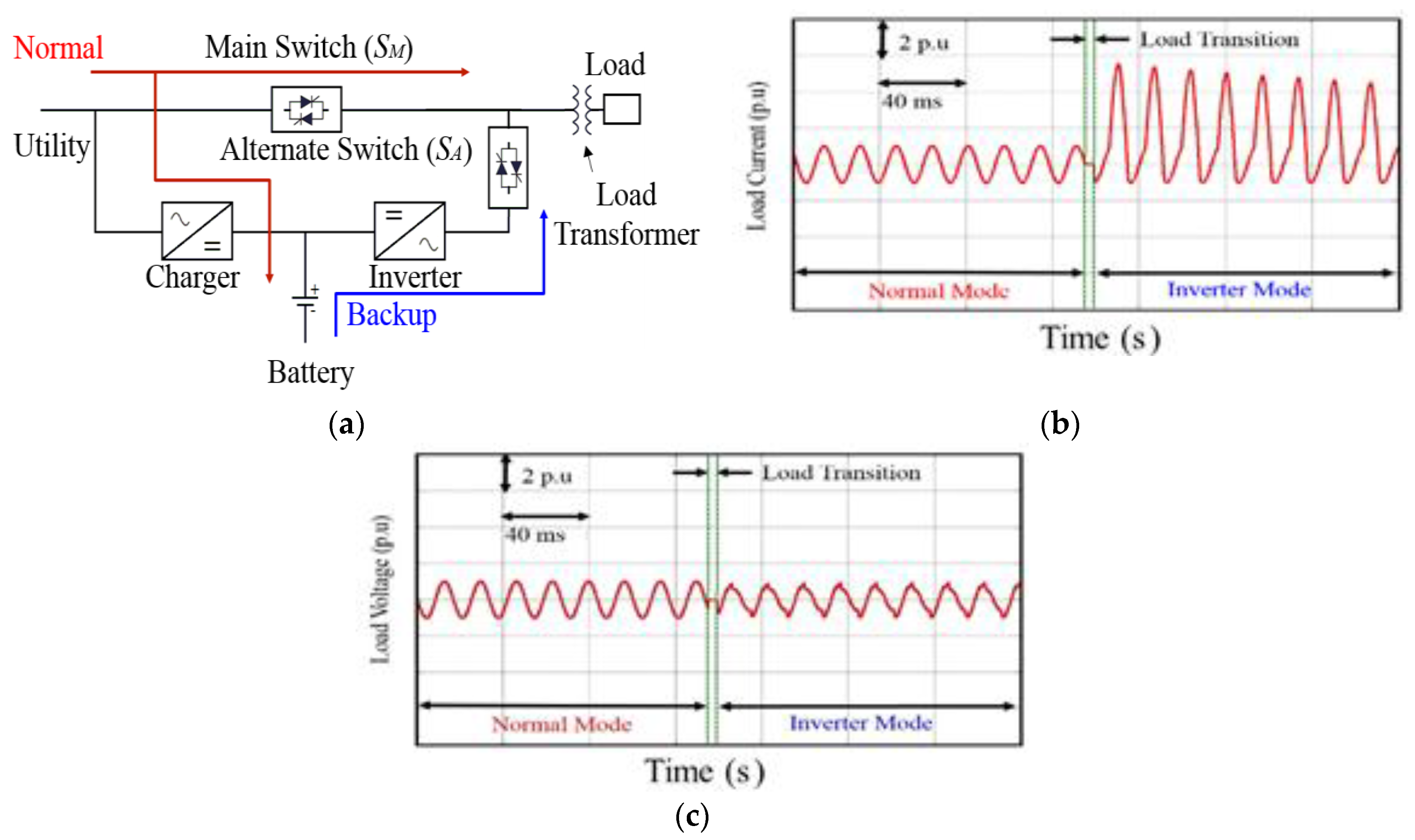
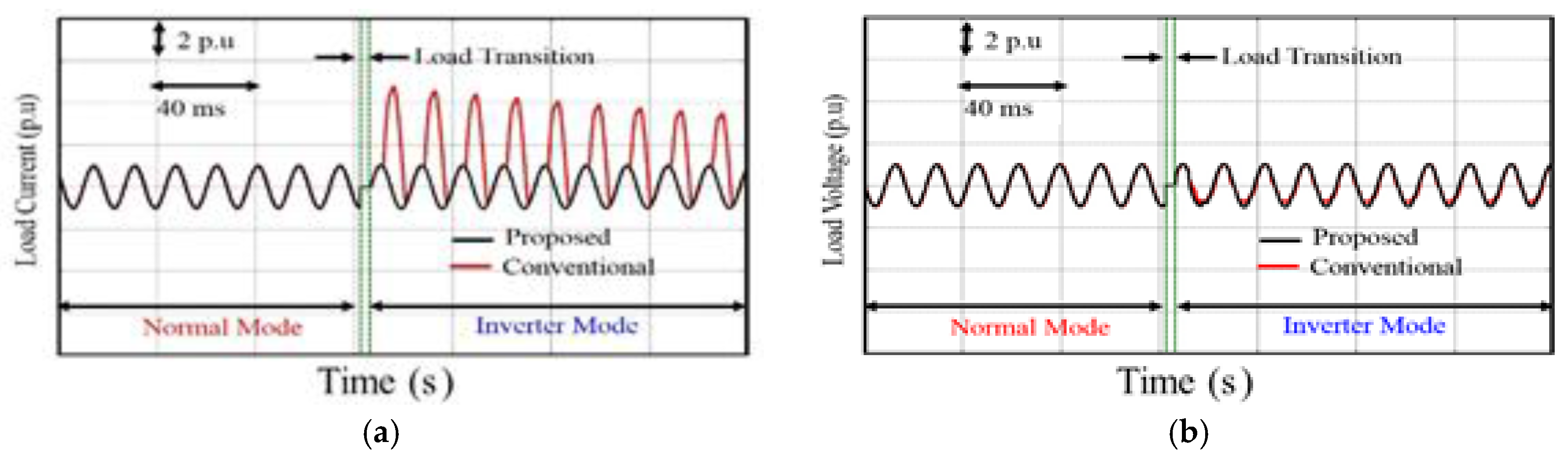
For the acceptable isolation of load from the utility, a load transformer is generally installed before the load as shown in
Figure 2a. The transition time interval, which did not affect the load current before
i.e., in case of load without the load transformer, can generate serious magnitude of inrush transient current during the starting of the UPS system while powering the transformer-coupled load.
Figure 2b,c shows the behavior of an offline UPS system during such circumstances. From the figure, it is evident that the load current reaches to 5.54 per unit (p.u) which is more than five and a half times higher than the rated steady-state magnitude.
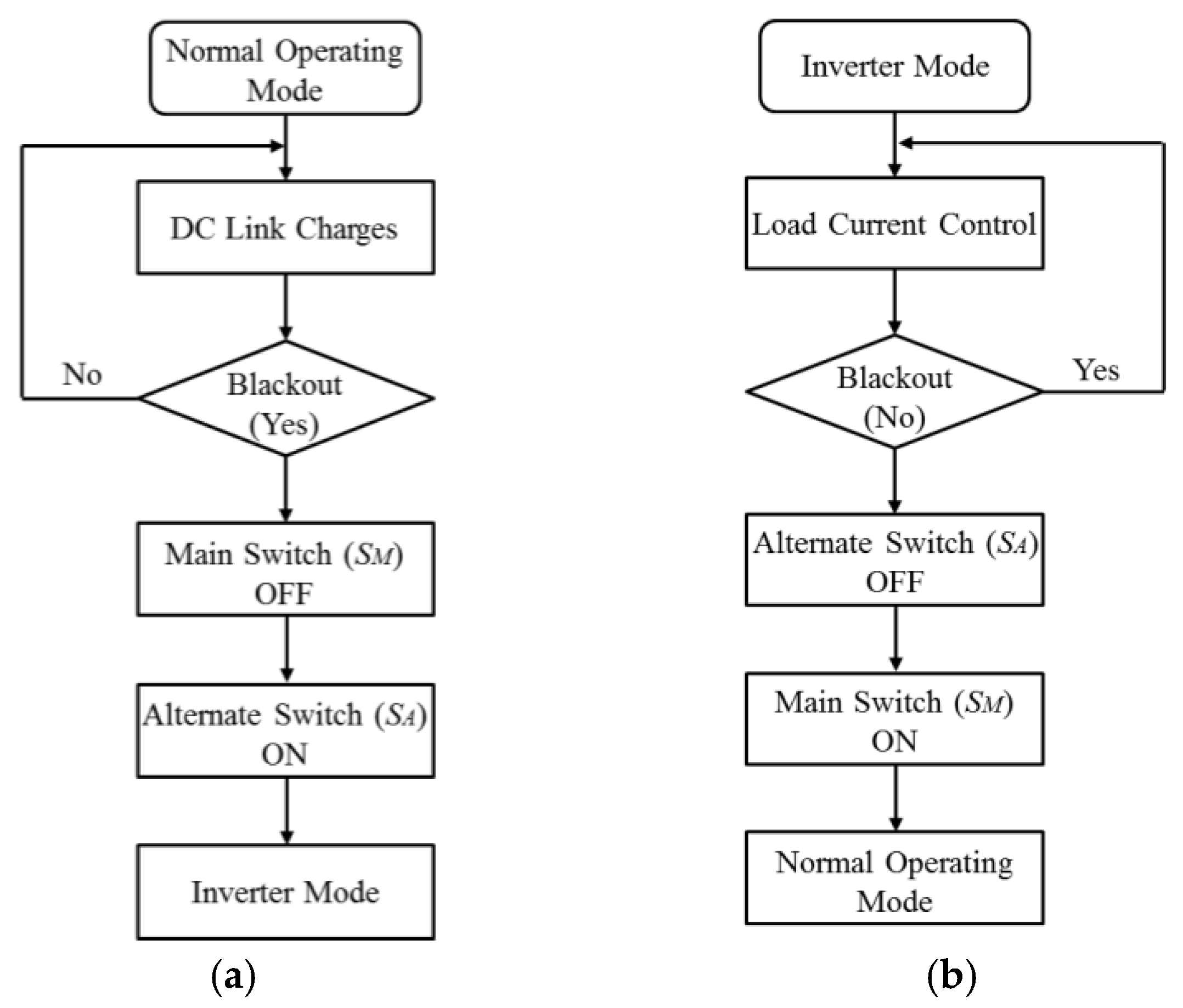
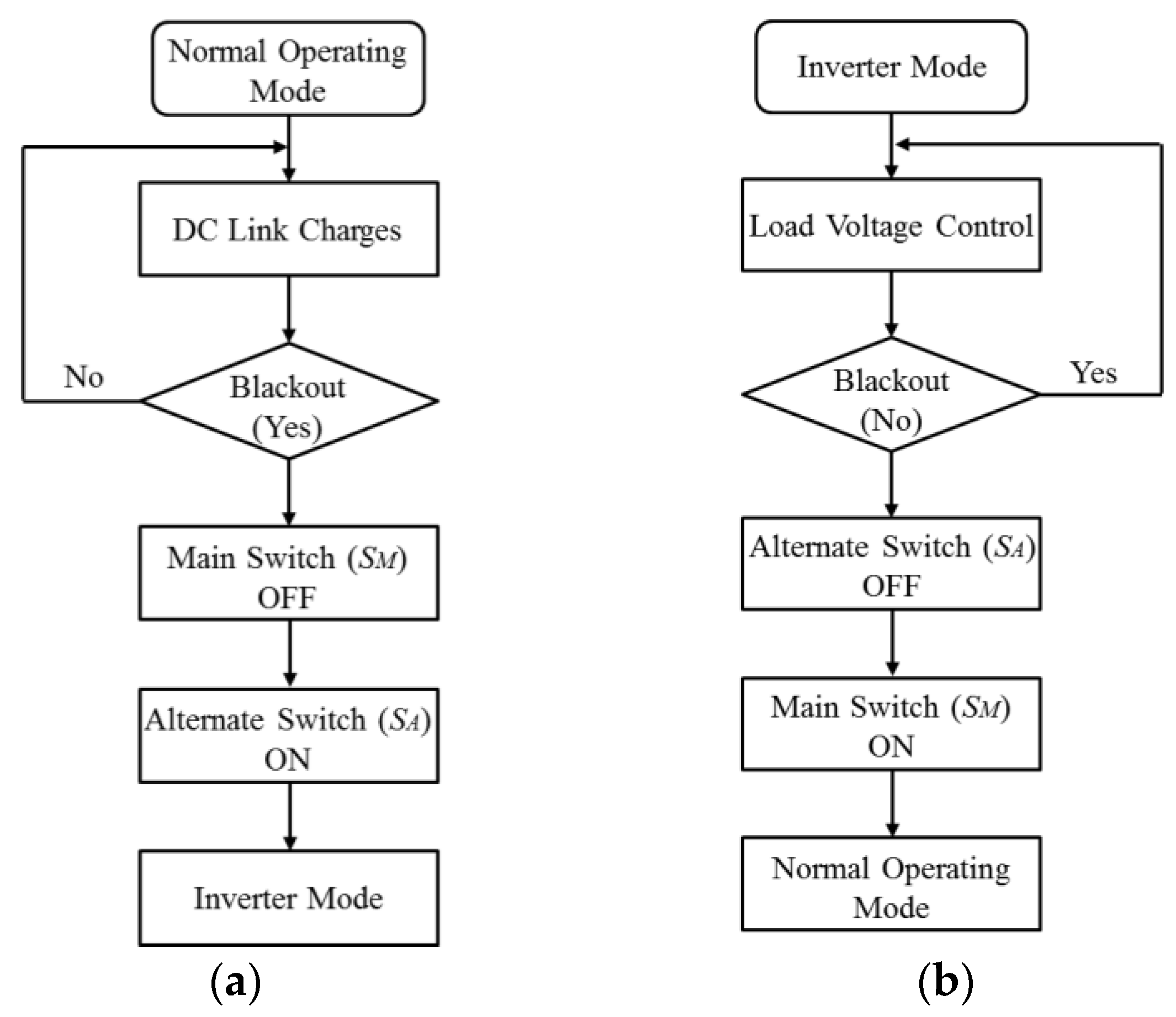
Figure 3a,b shows the flowcharts for a typical offline UPS system to illustrate the transfer of load from normal operating to the inverter modes, and
vice versa.
Figure 2.
(a) Basic diagram of a single-phase offline UPS system with load transformer; (b) load current; and (c) load voltage.
Figure 2.
(a) Basic diagram of a single-phase offline UPS system with load transformer; (b) load current; and (c) load voltage.
Figure 3.
Flowchart for the (a) normal operating; and (b) inverter modes of the conventional offline UPS system.
Figure 3.
Flowchart for the (a) normal operating; and (b) inverter modes of the conventional offline UPS system.
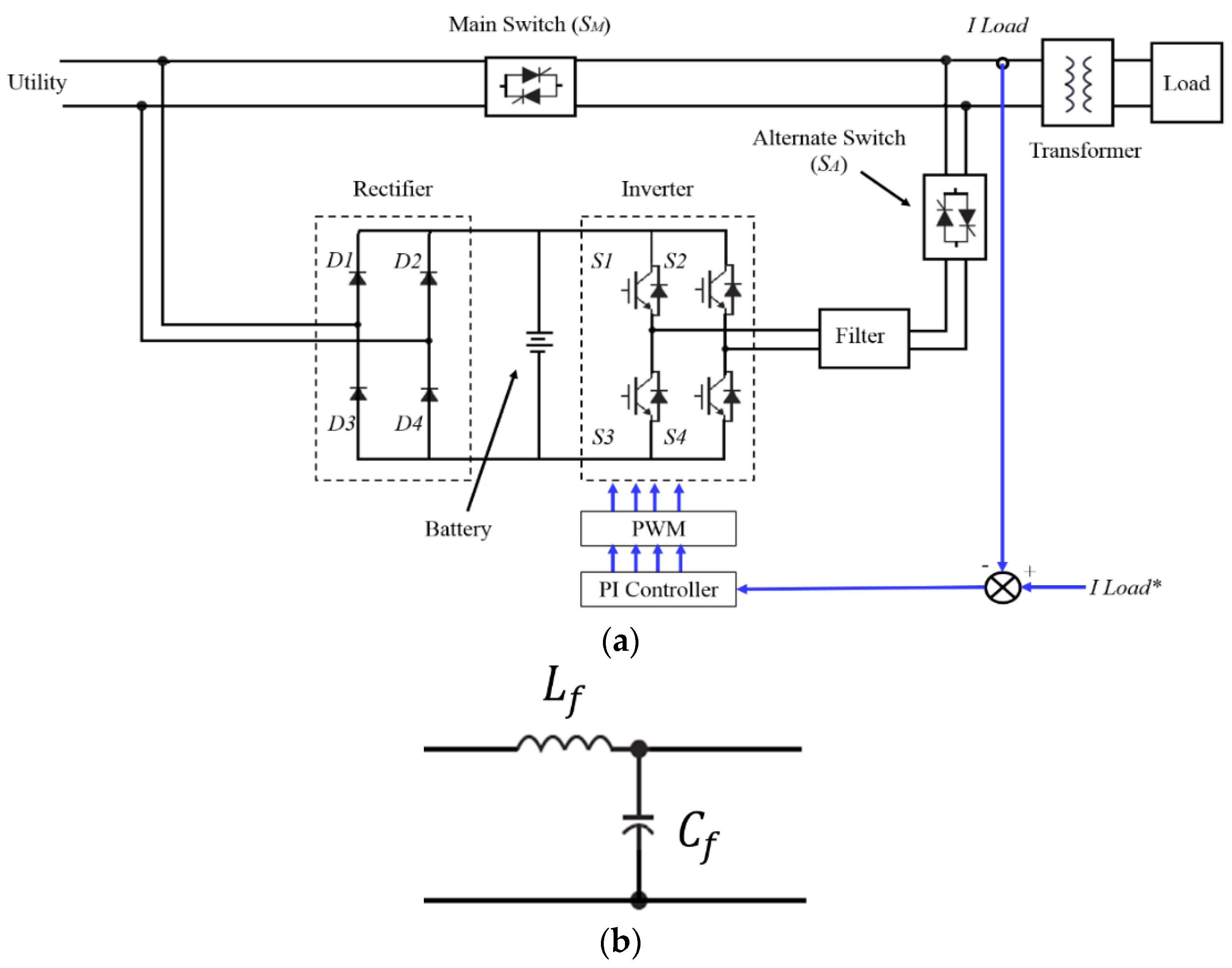
2.2. Proposed Single-Phase Offline UPS System
To eliminate the inrush current for an offline UPS system when it is powering the load transformer, this paper offers an offline UPS topology based on a current regulated inverter instead of the conventional PWM voltage source inverter. Basic operational principle of the suggested UPS system is similar as the conventional topology shown in
Figure 1a and
Figure 2a. However, the risk of inrush current is rejected by using a current control algorithm implemented in a stationary frame of reference.
Figure 4a,b shows the complete illustration of the proposed topology along with the filter circuit. As shown in
Figure 4b, the filter circuit consists of an inductor and a capacitor connected in parallel to each other to remove the current and voltage ripples of the inverter, respectively.
Figure 4.
(a) Complete diagram of the proposed single-phase UPS system with load transformer; and (b) filter circuit.
Figure 4.
(a) Complete diagram of the proposed single-phase UPS system with load transformer; and (b) filter circuit.
The current-regulating algorithm employed for the proposed UPS system uses an improved current control scheme which is ideally suited for controlling AC currents with and without motor loads through a PI controller, as illustrated in [
19]. Simplicity and ease in implementation are the only reasons for using this current control algorithm. Furthermore, a detailed analysis of the implemented current control strategy along its performance and stability issues are well discussed in [
19]. However, any of the recently well-developed current regulating schemes can also be used for this purpose. The transfer function of the proposed system powering a load without associated EMF
i.e., RL load is given by:
However, if the proposed UPS system is powering a motor load, same transfer function can be written as:
where
I*(s) is the reference command,
I(
s) is the inverter output
i.e., measured load current, a linear amplifier with a forward gain of
VDC is used for the replacement of PWM modulator,
Gc(
s) and
Gp(
s) are the transfer functions of controller and plant, respectively, and the motor load’s back EMF is modeled as a disturbance injection
D(
s) using simple control theory [
19]. However,
F(s) is the transfer function of the filter and is given by:
where
Lf is the filter inductance and
Cf is the filter capacitance, respectively.
The function of the PI controller in the system is to equate the load current to the reference command as diligently as possible while minimizing any error caused by the disturbance injection
D(
s). The transfer function of the plant is given by:
Gc(s) is given by:
where
τr is the integrator reset time and is the ratio of proportional and integral gain (
Kp/
Ki).
By substituting from Equations (4) and (5), the open loop forward path gain of this system is obtained as:
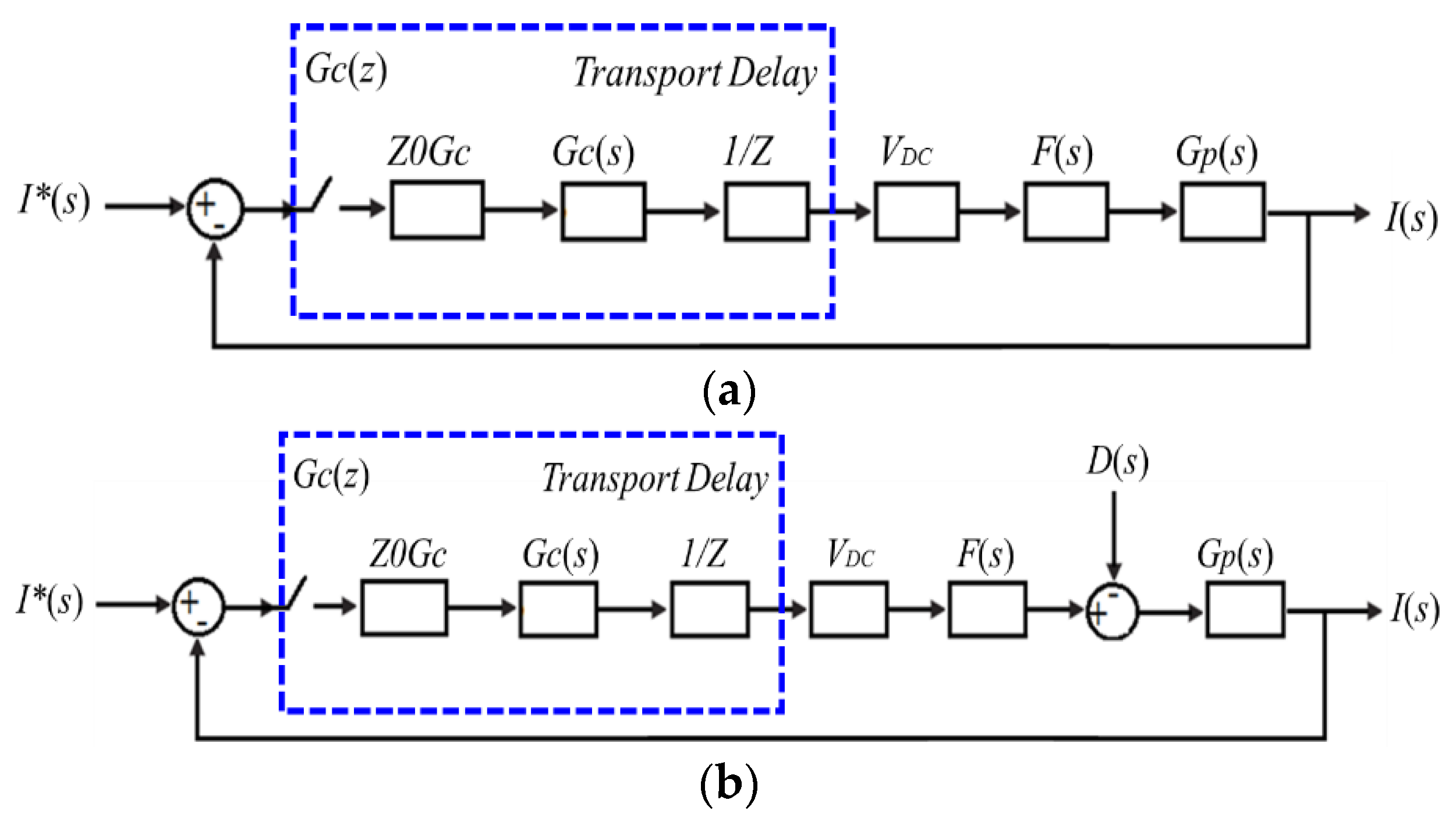
The operation of any control system is always influenced by two delays: (1) transport delay due to the PWM process and (2) sampling delay due to the digital control system. The total transport and sampling delay for the implemented current-regulating algorithm is about 0.75 [
20] of the carrier period. The PWM carrier period in this case is about 100 µs.
The control loop delays can be modeled by using Z-transform theory as discussed in [
21] with a zero-order-hold element to model sampling delay and a 1/
Z block in series with the controller to model transport delay. The average-value model diagram representations of the inverter with the properties of sampling and transport delays while powering an RL and motor loads are shown in
Figure 5a,b.
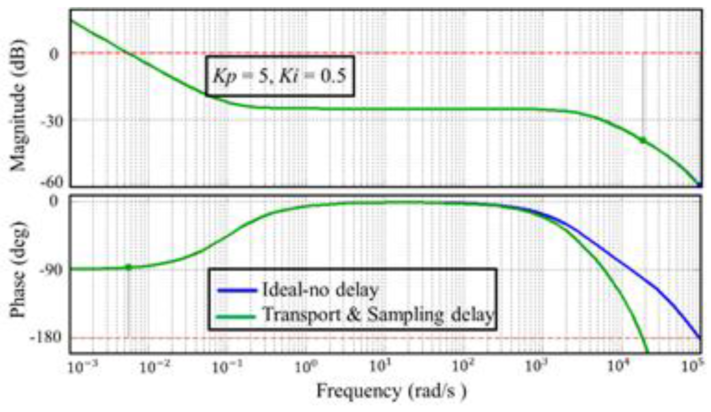
Figure 6 shows a Bode plot of Open Loop Forward Gain of the implemented current control algorithm, while considering transport and sampling delays. These plots are obtained under the conditions of passive RL load having
R = 90 Ω and
L = 10 mH, proportional gain
Kp = 5 and integral gain
Ki = 0.5, and total transport and sampling delays = 75 µs [
18,
19,
20]. From the figure it can be observed exactly that how the controller delays cause the system phase to now roll off past the −180° stability limit at high frequency. This makes the maximum value of
Kp to a value that keeps the system phase response less than −180° (
i.e., a positive phase margin) at the unity gain crossover frequency.
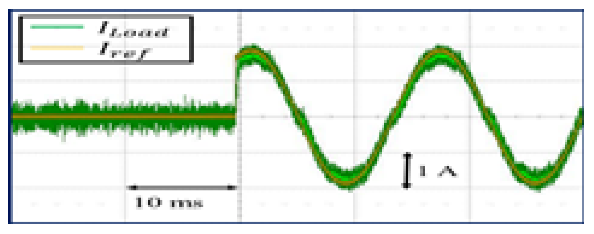
Figure 7 shows a comparative analysis of the experimental response of the implemented current regulator against the reference current. This figure shows that the response delay of the controller of the proposed UPS system obtained experimentally has insignificant magnitude and phase difference compared to the reference current [
22].
Figure 8a,b shows the flowcharts to explain the transition of load from normal operating to the inverter modes and from inverter to the normal operating modes of the proposed topology. As seen from the flowchart, the process of transition of load for the proposed UPS system is similar to that of conventional offline UPS topology except of the controller, as the proposed topology utilizes current control strategy however, the conventional topology work on voltage control algorithm.
Figure 5.
Average value diagram for the proposed system powering (a) RL load; and (b) motor load.
Figure 5.
Average value diagram for the proposed system powering (a) RL load; and (b) motor load.
Figure 6.
Bode plot of Open Loop Forward Path Gain for implemented controller.
Figure 6.
Bode plot of Open Loop Forward Path Gain for implemented controller.
Figure 7.
Experimental response of the current regulator implemented for the proposed system.
Figure 7.
Experimental response of the current regulator implemented for the proposed system.
Figure 8.
Flowchart for the (a) normal operating; and (b) inverter modes of the proposed system.
Figure 8.
Flowchart for the (a) normal operating; and (b) inverter modes of the proposed system.
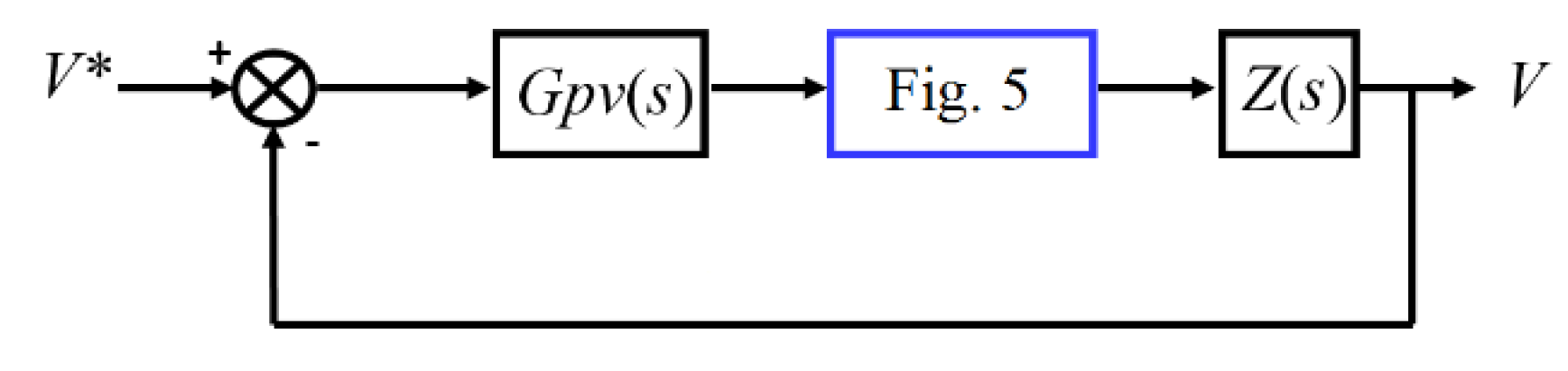
The reference current signal
I*(s) can be generated by using a voltage loop outside the current loop. Under such condition the voltage error sets the current command for the inner loop via controller. The outer loop controls the load voltage by changing the reference of inner loop [
23]. The inner loop controls the load current as discussed above. This enables the proposed single-phase UPS system to operate on flexible loading conditions. The average-value model diagram representation for the outer voltage loop of the proposed system is shown in
Figure 9 and the transfer function is given by:
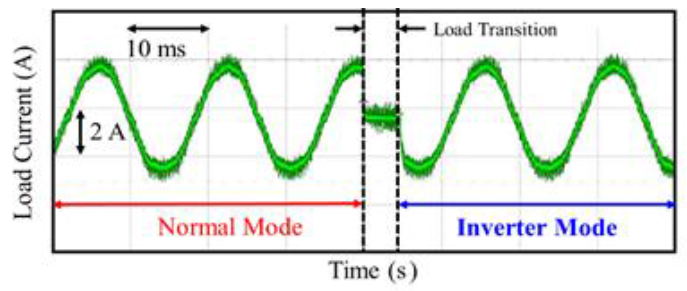
The performance of the proposed system is shown in
Figure 10, which suggests that the load current remains same as the case when the conventional offline UPS system was powering the load without the load transformer. The load current never exceeds 1 (p.u) at any stage during the load transition from the utility to the inverter. The load current and voltage is shown in
Figure 10a,b, respectively. Furthermore, the proposed UPS system offers the similar advantages of simple design, and high efficiency as that of conventional single-phase topology. The size, weight, and cost of the proposed topology is comparatively greater than the conventional topology since it employs a load transformer for isolation purpose. A detailed comparison of both (proposed and conventional topologies) is given in
Table 1.
Figure 9.
Average value model of the outer voltage loop of the proposed system.
Figure 9.
Average value model of the outer voltage loop of the proposed system.
Figure 10.
(a) Load current; and (b) load voltage of the proposed offline UPS system.
Figure 10.
(a) Load current; and (b) load voltage of the proposed offline UPS system.
Table 1.
Comparison of conventional and proposed offline UPS topologies.
Table 1.
Comparison of conventional and proposed offline UPS topologies.
| Attribute | Conventional Topology | Proposed Topology |
|---|
| Power Application | Low Power Applications | Low-Medium Power Applications |
| Power Capacity | 120% | 120% |
| Efficiency | High | High |
| Design | Simple | Simple |
| Isolation of Load | No | Best |
| Cost, Size and Weight | Low | High (due to load transformer) |
| Inrush Current Possibility | Yes | No |
| Issues with Non-Linear loads | Yes | No |
2.3. Inrush Current Phenomenon and Comparative Transient Behavior of the Conventional and Proposed Single-Phase Offline UPS Topologies
For the quantitative analysis of the inrush current phenomenon associated with a single-phase offline UPS system while powering a load transformer, consider the source voltage applied to the transformer is:
The resultant flux under steady-state operation is:
The initial value of the transient flux is equal in magnitude and opposite in sign to that given in following equation:
Subscript t indicates the transient flux.
The instantaneous flux (λ) at any time
t, is:
where
t ≥ 0.
To define the mechanism of generation of inrush current during the change of load from the utility to the inverter consider the following equation:
where λ is the instantaneous flux and
v is the voltage drop at the primary side of the load transformer.
The above equation suggests that the derivative of instantaneous flux with respect to time is proportional to the instantaneous voltage drop at the primary side of the transformer. For a load transformer, voltage, and flux waveforms are shifted by 90° during normal operation. However, during the transition of load these waveforms act differently. As the transition occurs and inverter restores the load voltage, the magnetic flux of the transformer increases above the normal operating value. Since the magnetization curve is nonlinear, this magnitude of flux causes the saturation of the load transformer. Under such a condition, high magnitude of MMF is necessary to cause flux. Hence, the current, that produces the MMF to root flux, will excessively increase beyond its normal peak. For the magnitude of the first cycle of inrush transient current, consider the following equation:
where
L is the air core inductance,
R is the total DC resistance,
Bn,
Br, and
Bs are the rated, remanent, and saturation flux densities of the transformer and
Vm is the maximum applied voltage [
24,
25,
26].
Equations (13) and (14) suggest that the magnitude of inrush current depends on the parameters
i.e., impedances of windings and the switching instant of the load transformer at which inverter injects the load voltages. To investigate the effect of winding impedances on the magnitude of inrush current study have been performed using four load transformers (T
1, T
2, T
3, and T
4) with different impedances. The parameters of these investigated transformers are given in the following
Table 2:
Table 2.
Parameters of investigated load transformers.
Table 2.
Parameters of investigated load transformers.
| Transformer | T1 | T2 | T3 | T4 |
|---|
| Rating (kVA) | 1 | 1 | 1 | 1 |
| Voltage | 220 | 220 | 220 | 220 |
| Turn Ratio | 1:1 | 1:1 | 1:1 | 1:1 |
| R1 (Ω) | 1.535 | 1.180 | 0.908 | 0.698 |
| R2 (Ω) | 0.511 | 0.393 | 0.302 | 0.232 |
| L1 (mH) | 2.059 | 1.584 | 1.218 | 0.937 |
| L2 (mH) | 0.686 | 0.527 | 0.406 | 0.312 |
Table 3 shows the magnitude of first, second, and third peaks of inrush current when the load transformers with the above parameters are used. The operating conditions for all load transformers are same in order for a more accurate comparison. From the results it is observed that as the impedances of the load transformer increases, the magnitude of inrush current decreases. Furthermore, increase in the impedances also fastens the decay process of inrush current.
Table 3.
Comparison of maximum inrush current for different load transformers.
Table 3.
Comparison of maximum inrush current for different load transformers.
| Transformer | First Peak (p.u) | Second Peak (p.u) | Third Peak (p.u) |
|---|
| T1 | 2.886 | 2.761 | 2.659 |
| T2 | 2.911 | 2.811 | 2.730 |
| T3 | 2.937 | 2.851 | 2.788 |
| T4 | 2.973 | 2.897 | 2.834 |
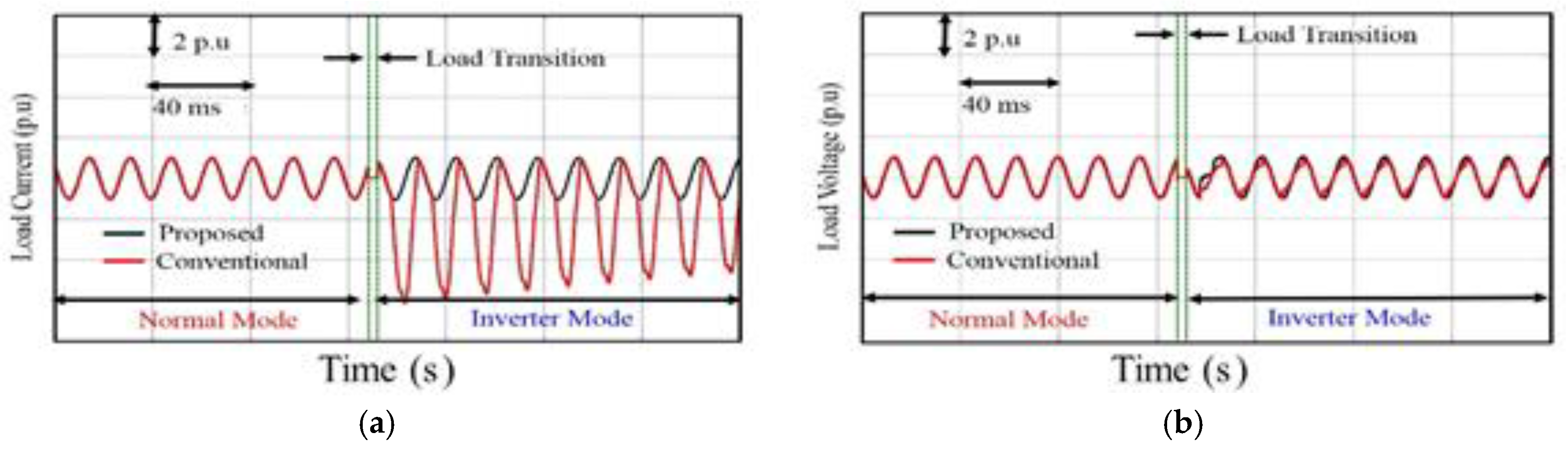
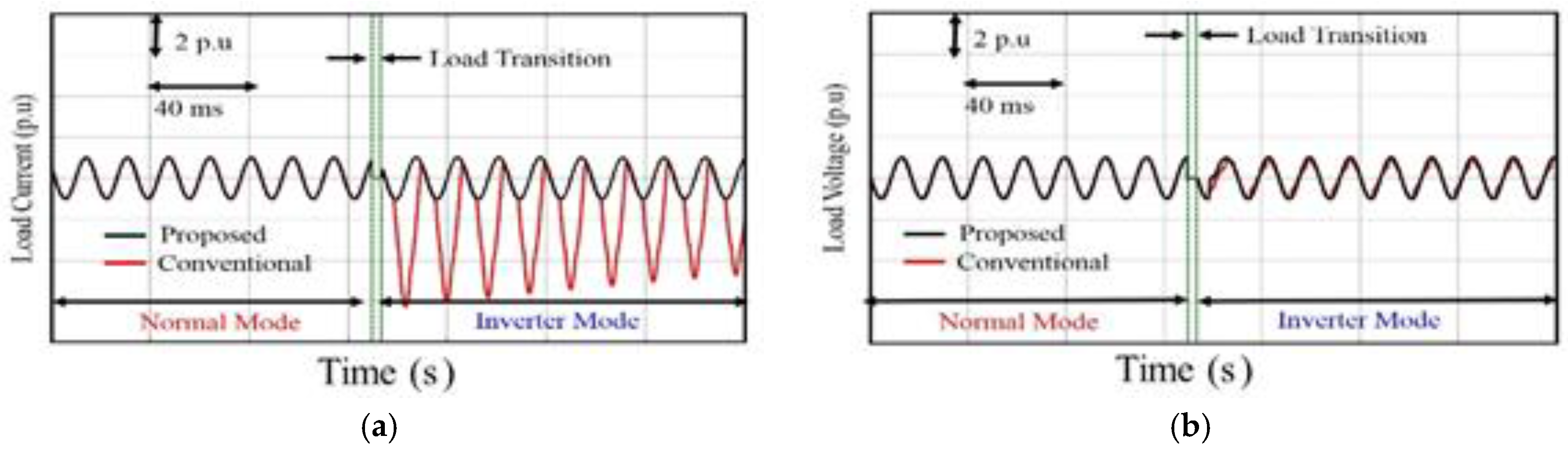
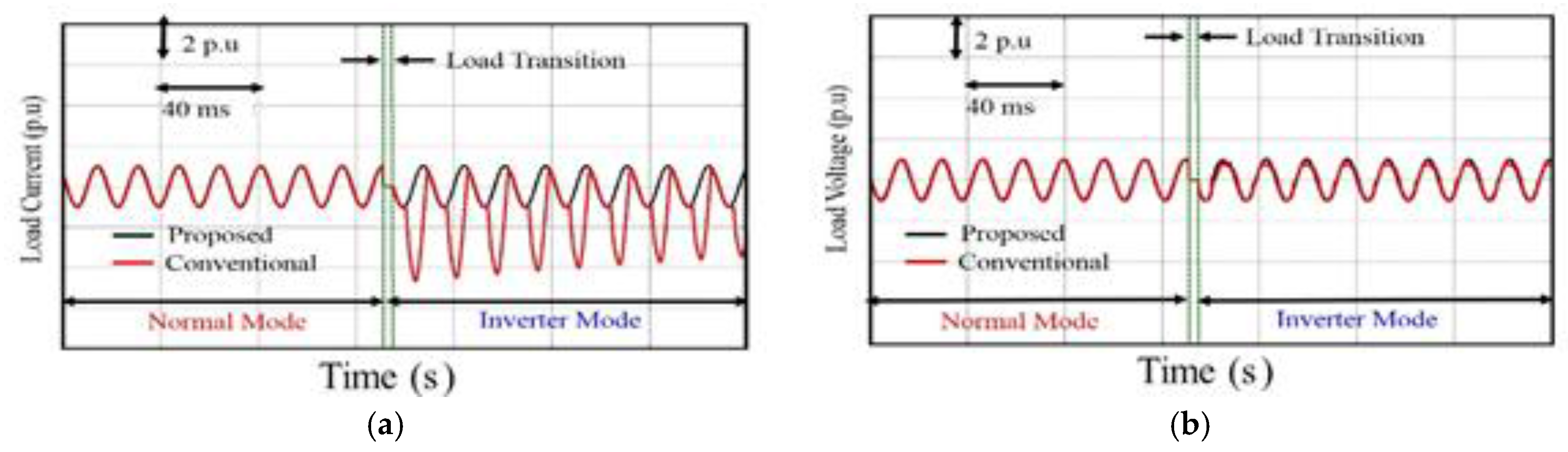
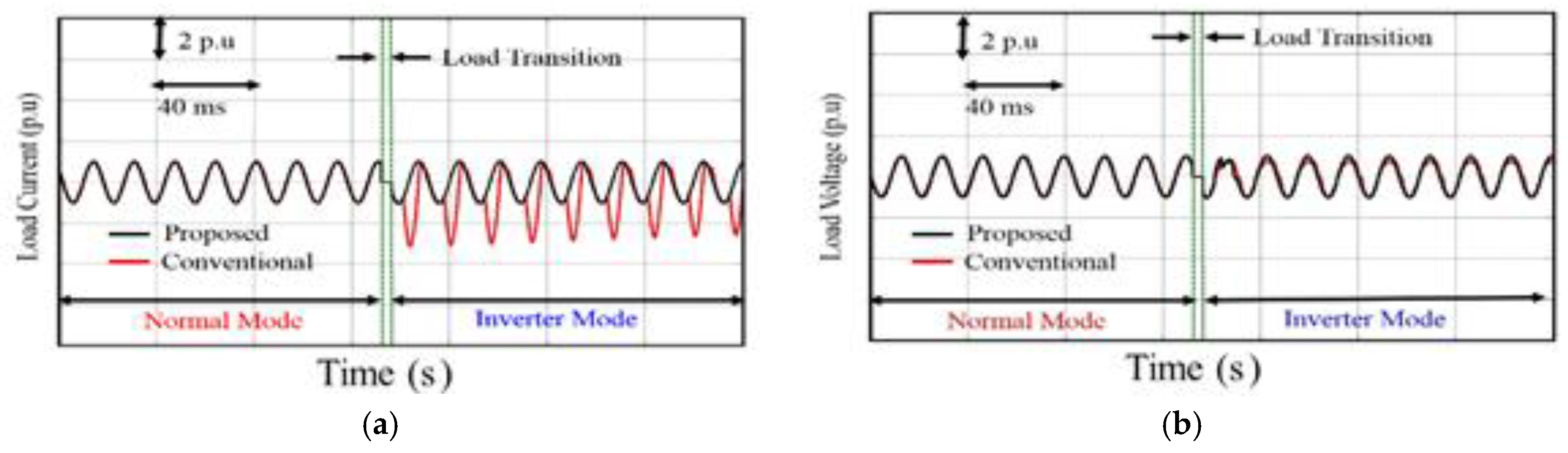
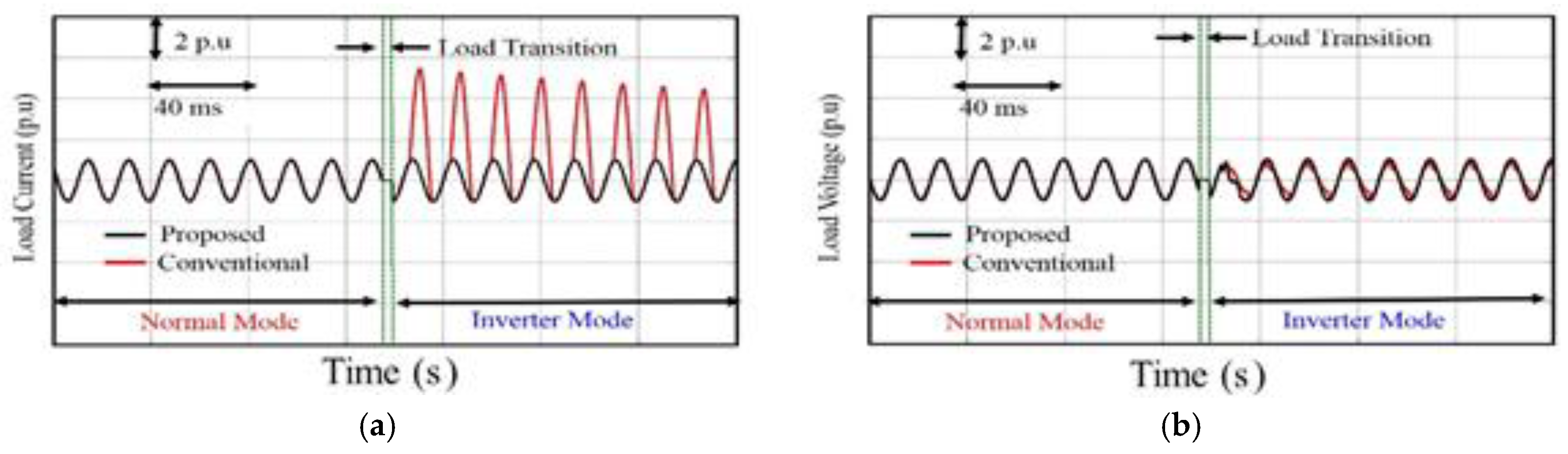
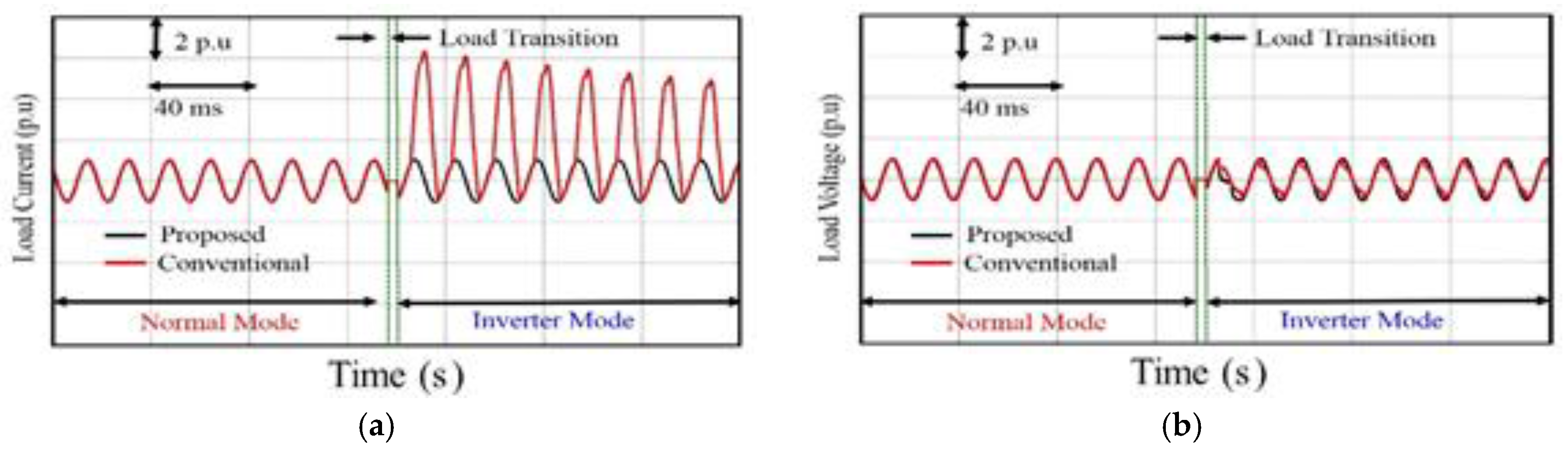
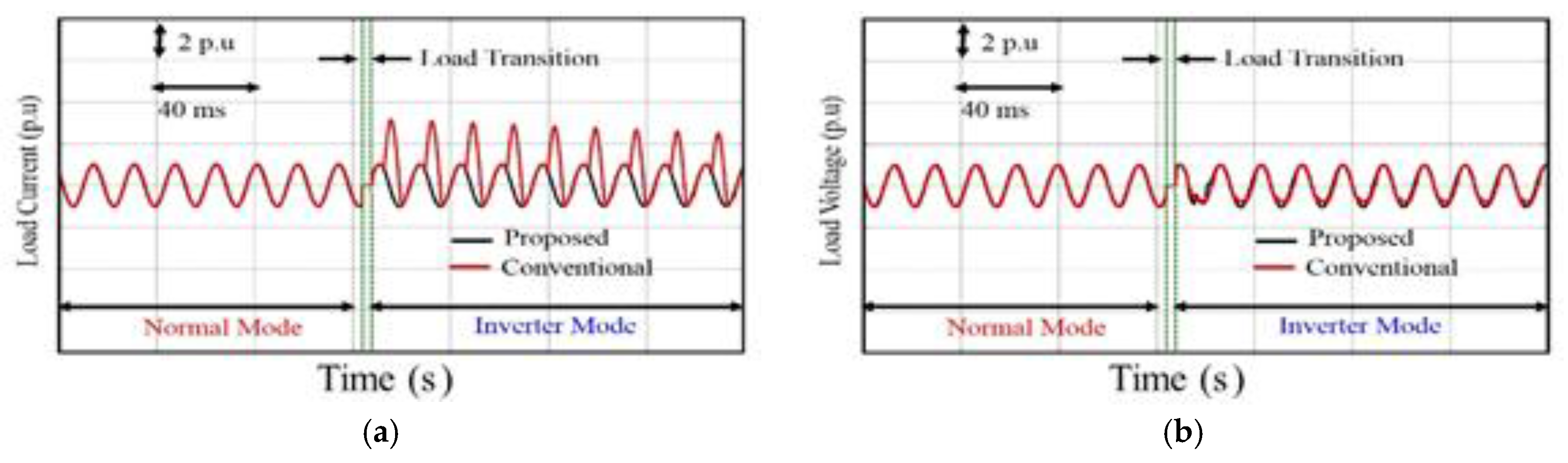
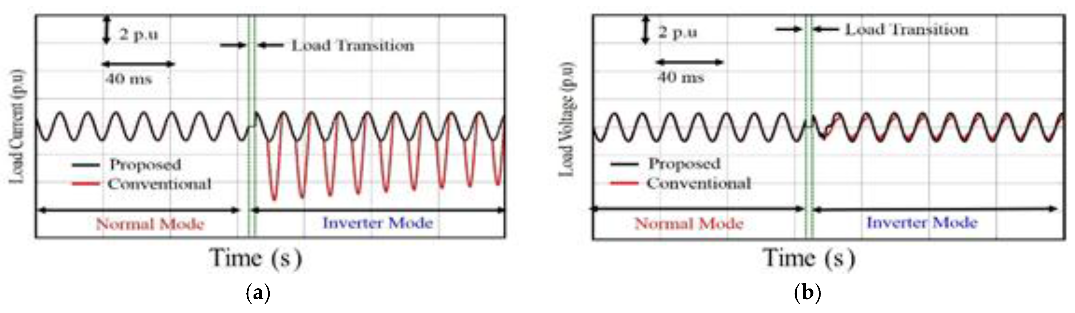
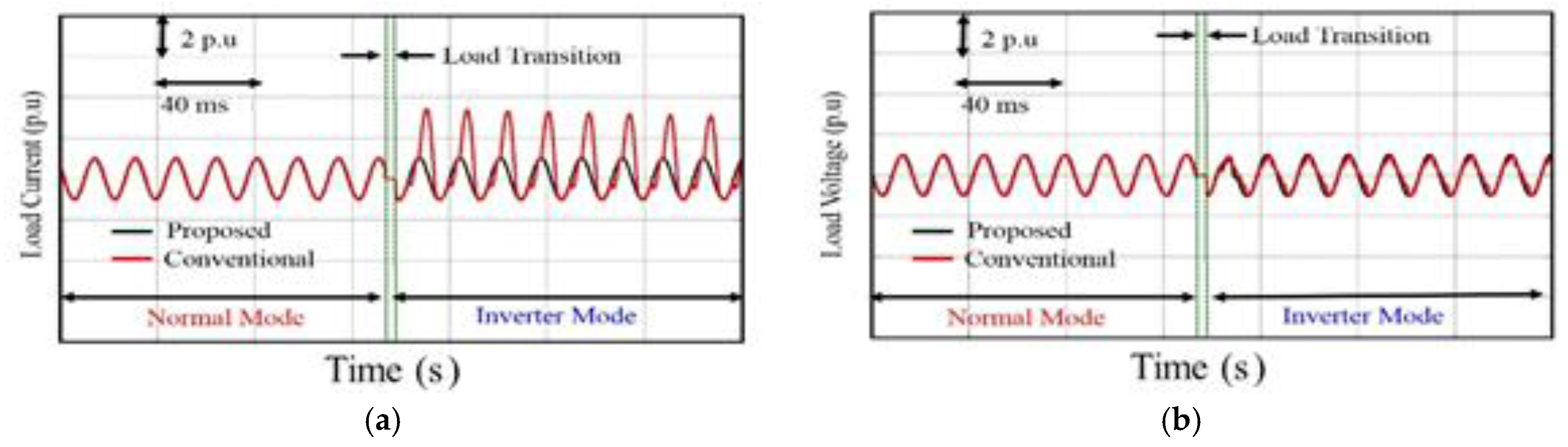
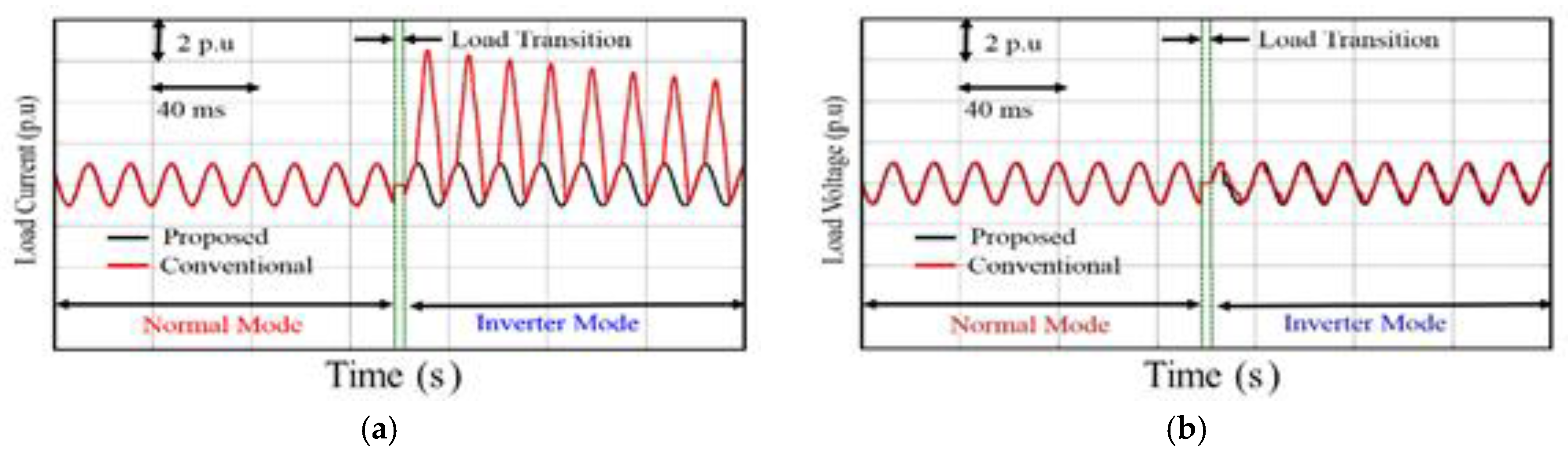
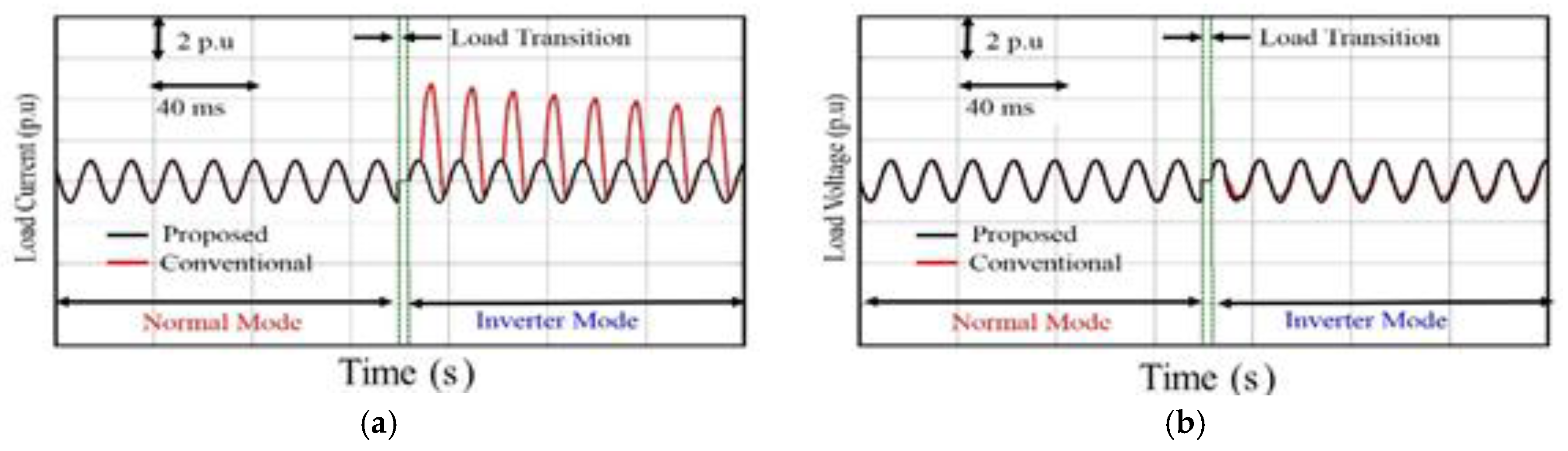
To study the performance of the conventional and proposed offline UPS systems, investigations have been carried out over the wide range of switching instants for the load transformer when the inverter injects the load voltage shown in
Figure 11.
Figure 12a–
Figure 24a show the load currents. However, the load voltages are shown in
Figure 12b–
Figure 24b. Transformer with the largest inrush current magnitudes shown in
Table 3.
i.e., T
4 is used for this purpose. From the results it is evident that the magnitude of inrush current using the conventional offline UPS topology is different at different switching instants and it attains the maximum value when the inverter injects the load voltage at an angle of 330°. However, the load current for the proposed single-phase UPS system remains the same regardless the switching conditions. It never exceeds the prescribed value at any point as the transition of load from utility to the inverter occurs.
Figure 11.
Switching conditions for the load transformer.
Figure 11.
Switching conditions for the load transformer.
Figure 12.
(a) Load current; and (b) load voltage for the conventional and proposed single-phase offline UPS topologies when the inverter voltage is injected at 0°.
Figure 12.
(a) Load current; and (b) load voltage for the conventional and proposed single-phase offline UPS topologies when the inverter voltage is injected at 0°.
Figure 13.
(a) Load current; and (b) load voltage for the conventional and proposed single-phase offline UPS topologies when the inverter voltage is injected at 30°.
Figure 13.
(a) Load current; and (b) load voltage for the conventional and proposed single-phase offline UPS topologies when the inverter voltage is injected at 30°.
Figure 14.
(a) Load current; and (b) load voltage for the conventional and proposed single-phase offline UPS topologies when the inverter voltage is injected at 60°.
Figure 14.
(a) Load current; and (b) load voltage for the conventional and proposed single-phase offline UPS topologies when the inverter voltage is injected at 60°.
Figure 15.
(a) Load current; and (b) load voltage for the conventional and proposed single-phase offline UPS topologies when the inverter voltage is injected at 90°.
Figure 15.
(a) Load current; and (b) load voltage for the conventional and proposed single-phase offline UPS topologies when the inverter voltage is injected at 90°.
Figure 16.
(a) Load current; and (b) load voltage for the conventional and proposed single-phase offline UPS topologies when the inverter voltage is injected at 120°.
Figure 16.
(a) Load current; and (b) load voltage for the conventional and proposed single-phase offline UPS topologies when the inverter voltage is injected at 120°.
Figure 17.
(a) Load current; and (b) load voltage for the conventional and proposed single-phase offline UPS topologies when the inverter voltage is injected at 150°.
Figure 17.
(a) Load current; and (b) load voltage for the conventional and proposed single-phase offline UPS topologies when the inverter voltage is injected at 150°.
Figure 18.
(a) Load current; and (b) load voltage for the conventional and proposed single-phase offline UPS topologies when the inverter voltage is injected at 180°.
Figure 18.
(a) Load current; and (b) load voltage for the conventional and proposed single-phase offline UPS topologies when the inverter voltage is injected at 180°.
Figure 19.
(a) Load current; and (b) load voltage for the conventional and proposed single-phase offline UPS topologies when the inverter voltage is injected at 210°.
Figure 19.
(a) Load current; and (b) load voltage for the conventional and proposed single-phase offline UPS topologies when the inverter voltage is injected at 210°.
Figure 20.
(a) Load current; and (b) load voltage for the conventional and proposed single-phase offline UPS topologies when the inverter voltage is injected at 240°.
Figure 20.
(a) Load current; and (b) load voltage for the conventional and proposed single-phase offline UPS topologies when the inverter voltage is injected at 240°.
Figure 21.
(a) Load current; and (b) load voltage for the conventional and proposed single-phase offline UPS topologies when the inverter voltage is injected at 270°.
Figure 21.
(a) Load current; and (b) load voltage for the conventional and proposed single-phase offline UPS topologies when the inverter voltage is injected at 270°.
Figure 22.
(a) Load current; and (b) load voltage for the conventional and proposed single-phase offline UPS topologies when the inverter voltage is injected at 300°.
Figure 22.
(a) Load current; and (b) load voltage for the conventional and proposed single-phase offline UPS topologies when the inverter voltage is injected at 300°.
Figure 23.
(a) Load current; and (b) load voltage for the conventional and proposed single-phase offline UPS topologies when the inverter voltage is injected at 330°.
Figure 23.
(a) Load current; and (b) load voltage for the conventional and proposed single-phase offline UPS topologies when the inverter voltage is injected at 330°.
Figure 24.
(a) Load current; and (b) load voltage for the conventional and proposed single-phase offline UPS topologies when the inverter voltage is injected at 360°.
Figure 24.
(a) Load current; and (b) load voltage for the conventional and proposed single-phase offline UPS topologies when the inverter voltage is injected at 360°.


