Article

A Decentralized Control Method for Distributed Generations in an Islanded DC Microgrid Considering Voltage Drop Compensation and Durable State of Charge

Korea Electrotechnology Research Institute, Changwon 51543, Korea
*
Author to whom correspondence should be addressed.
Energies 2016, 9(12), 1070; https://doi.org/10.3390/en9121070
Submission received: 10 October 2016 / Revised: 3 December 2016 / Accepted: 8 December 2016 / Published: 16 December 2016
(This article belongs to the Special Issue Microgrids 2016)

Abstract

:
This paper presents a decentralized control method for distributed generations (DGs) in an islanded direct current (DC) microgrid. In most typical DC microgrids, a decentralized control method is based on a voltage droop control method. However, the grid voltage differs from node to node due to line voltage drop, and hence the power sharing ratio among DGs cannot be matched with as desired value. Especially in an islanded DC microgrid including an energy storage system as a voltage source, it is difficult for DGs to maintain the charge state of the ESS in a decentralized way. To overcome this problem, state of charge (SOC)-voltage droop control is applied to the ESS. By using the proposed droop method, the SOC information can be assigned to the grid voltage, and hence the other DGs are able to support the SOC in a decentralized way. For DGs to enhance the accuracy of the SOC estimation, voltage drop is compensated for based on forecasting data and line impedance data. The simulation is modeled and implemented using Power System Computer Aided Design/Electromagnetic Transients for DC (PSCAD/EMTDC, version 4.2, Winnipeg, Manitoba, Canada) and the simulation results show that the capability to maintain SOC as well as the system voltage profile are improved by using the proposed method.

1. Introduction

Direct current (DC) microgrids are being increasingly developed and studied due to the fact that they are more efficient than alternating current (AC) systems from the perspective of energy conversion efficiency [1,2,3]. This is due to the fact that most modern loads require DC power, to supply them with DC power directly rather than with AC power as conventional power systems do. For DC load examples, there are battery energy storage systems (BESSs), electric vehicles, laptops, personnel computers, lightings, televisions, data centers, refrigerators, and air conditioners [4,5,6]. Moreover, since most renewable energy sources (RESs) and energy storage system (ESSs) generate DC power, rectification and inversion power electronic converter stages are eliminable in DC microgrids [7]. Furthermore, a DC power system is more efficient than an AC power system from the perspective of line loss of power for the same voltage level.
An islanded DC microgrid is composed of loads, ESS, distributed generations (DGs), and an energy management system (EMS) or a central controller. Note that in a centralized control microgrid, a central controller can be regarded as an EMS [8]. The reason for using EMS is to achieve control accuracy as described in [9] and to enhance system control accuracy as described in [10]. Some references [8,11,12] described the detailed pros and cons of centralized and decentralized control methods of microgrid. The centralized control enables system optimization; however, it does not exhibit the desirable plug-and-play feature [8]. On the other hand, the decentralized control can incorporate new DG units without continuous changes to controller settings, but it cannot implement operations requiring high levels of coordination [8]. Reference [11] shows that a decentralized EMS is technically feasible and economically competitive. Reference [12] presents a multi agent system for intelligent demand-side management of the poly-generation microgrid topology, which also includes grey prediction algorithms for better management. Typically, ESS is controlled in two different modes—constant power (current) mode and constant voltage mode. While the ESS is controlled in constant power mode, the state of charge (SOC) can be adjusted by the ESS itself since the output power can be controlled as desired. While the ESS is controlled in constant voltage mode, the output power varies according to change of system load. In this case, the SOC should be controlled by other DGs and EMS. EMS receives SOC data and orders dispatchable DGs to output their power to maintain the SOC value at the desired level. The EMS cannot be used in case of emergency, such as communication failure, and hence the SOC cannot be supported by other DGs, which is one of the major disadvantages of a centralized control method. To enhance system reliability, a decentralized control method is used alone or to support the EMS (centralized control method). Still, there are some disadvantages of a decentralized control method. Among those disadvantages, lack of SOC information and poor grid voltage profile are focused in this paper.
Typically, in a decentralized control method, power sharing is implemented by the voltage droop control method. The advantages of the voltage droop control method are that it can share power and can compensate voltage drop. However, since the system voltage differs from node to node due to line voltage drop, DGs cannot share same amount of load even if droop coefficients are same. The most significant problem of the decentralized control method while using the ESS as a voltage source is the lack of SOC information for dispatchable DGs in an islanded DC microgrid. In a decentralized control method, SOC information cannot be transferred to dispatchable DGs since no communication system is used. Therefore, ESS may not be durable while it is controlled as constant voltage mode since dispatchable DGs cannot support the SOC.
Several researches have been studied to develop control methods for islanded (standalone) DC microgrids. Reference [13] investigated control and operation of a DC microgrid, which can be operated at grid-connected or island modes. It suggests load shedding if the voltage of BESS drops below a certain value. In [14], BESS is controlled as a constant voltage mode and its output voltage is adjusted by output current and droop coefficient. Similar to [13], load is shed while the grid voltage or the SOC drops below a certain level. However, in both [13,14] there are no control methods for durable operation of ESS. In [15], the DC grid voltage is divided into five levels and a different operation mode is applied to each voltage level. With the proposed method in [15], the ESS cannot be charged while its SOC level is low. Reference [16] presented a double-layer hierarchical control strategy to overcome the control challenge associated with the coordination of multiple batteries within one standalone microgrid. However, it requires a communication system (which may degrade the system reliability) for a hierarchical control strategy.
To overcome the disadvantages of the decentralized control method that is the focus of this paper (lack of SOC information), a power control method based on SOC and grid voltage with line voltage drop compensation is proposed. To this end, SOC-voltage droop is applied to the ESS and voltage droop with voltage drop compensation is applied to DGs. By using the proposed control method, SOC deviation from the specified reference value can be reflected in the grid voltage. Dispatchable DGs can support SOC by using the proposed power control method by estimating the SOC deviation which is assigned on the grid voltage. Hence, the SOC can be recovered close to the desired value in a decentralized control method, which could never be implemented by the previous works. The voltage drop compensation aids the power control of DGs to compensate voltage differences between nodes due to line voltage drop. The simulation is modeled and implemented by PSCAD/EMTDC and the simulation results show that the SOC maintaining capability as well as the system voltage profile is improved by using the proposed method.
The rest of this paper is organized as follows. Section 2 shows the proposed control scheme of ESS and DG. Section 3 presents the system configuration that is used in this study. Section 4 shows the simulation results and discussion, and Section 5 concludes the paper.

2. Control Scheme of Energy Storage System and Distributed Generation

2.1. Control Scheme of Energy Storage System

The ESS is controlled as the voltage source of the islanded DC microgrid. Since there is no communication infrastructure in a decentralized control method, the ESS has to send SOC information without a communication link. In a DG microgrid, the grid voltage is the only parameter that can exchange the real-time system information. Hence, to reflect the SOC data in the grid voltage, the control scheme of ESS output voltage is shown in Figure 1, where SOCref is the reference value of the SOC, mess is SOC-voltage droop coefficient, Vnom is the nominal voltage of the DC microgrid, and VESS,ref is the reference output voltage of ESS that goes into the voltage controller of the ESS. The reference value of the SOC can be determined by the system operator or the ESS owner to the desired value. By using the proposed method, DGs tend to maintain SOC at the reference value, SOCref. This means that if the SOC exceeds its reference value, DGs will decrease their power and if the SOC falls below the reference value, DGs will increase their power. If optimal scheduling is implemented in the system, the reference value of SOC can be set as a scheduled value of SOC. This might be helpful to prevent a short-term (shorter time than a scheduling time interval) SOC deviation. However, this paper focuses on a smaller time scale than the scheduling time interval (usually an hour).
The SOC is estimated by integrating output power since the relationship between the output power and the SOC can be expressed as [17]:
S O C = S O C i P E S S × P r a t e V E S S × I E S S , r a t e × C r a t e
where SOCi is the initial value of the SOC, PESS is the output power of the ESS, Prate is the rating power of the ESS, VESS is the output voltage of the ESS, IESS,rate is the rated current of the ESS, and Crate is the rate capacity of the ESS. The initial value of SOC should be estimated by measuring the battery voltage, however it is assumed that the initial value of SOC is given in this study. Since the output power of ESS is given as:
P E S S = V E S S × I E S S
where IESS is the output current of the ESS, by substituting Equation (2) into Equation (1), the following equation can be derived:
S O C = S O C i I E S S × K E S S
where:
K E S S = P r a t e I E S S , r a t e × C r a t e
which is constant value.
The SOC-voltage droop coefficient mess is shown in Figure 2 and can be given as:
m e s s = V U p L i m V L o L i m S O C U p L i m S O C L o L i m
where VUpLim and VLoLim are the upper and lower limits of the grid voltage, respectively, and SOCUpLim and SOCLoLim are the upper and lower limits of the SOC, respectively. According to the grid code referred to in [18], VUpLim and VLoLim are 1.1 p.u. and 0.9 p.u., respectively. SOCUpLim and SOCLoLim can be determined by the system operator or the ESS owner in order to set allowable operation range of the SOC. Since the SOC level affects the expected life of the battery [19], the system operator or the ESS owner should determine the allowable SOC range with consideration for the expected life of the battery. However, consideration of the economic perspective of the battery is out of scope of this paper. In this paper, SOCUpLim and SOCLoLim are arbitrarily set to 0.9 p.u. and 0.3 p.u., respectively. These values can be changed by the system operator or the ESS owner with the consideration of a battery type, a battery life cycle, load pattern of the DC microgrid, etc.
From Figure 2, it can be noticed that the ESS will maintain output voltage as Vnom as long as its SOC remains at SOCref. Hence, if dispatchable DGs attempt to recover the SOC at SOCref, the grid voltage also tend to remain close to the nominal value. However, the output voltage of ESS must be limited within the allowable range based on the grid code, whereas the SOC falls below its lower limit or exceeds its upper limit as it is discharged or charged.
By applying the control scheme shown in Figure 1 to the ESS in an islanded DC microgrid, the SOC information is reflected to the grid voltage and the allowable operation range of the SOC is matched to the allowable range of the grid voltage. Hence, other DGs in an islanded microgrid can asymptotically estimate the SOC level of the ESS by measuring their terminal voltages. For instance, if a DG’s terminal voltage is low, we can estimate that the SOC level is low. Hence, a DG can determine that it will increase its power to support the SOC in a decentralized way. However, the exact value of the SOC cannot be delivered through the grid voltage since the voltage drops across the line resistance. This problem can be solved to some extent by the voltage drop compensation that will be discussed in the next subsection.

2.2. Control Scheme of Distributed Generation

Dispatchable DGs are controlled as a current source in order to support the SOC and to share load among them. Non-dispatchable DGs, such as wind turbines (WTs) and photovoltaics (PVs), are controlled with the maximum power point tracking (MPPT) control method to maximize their energy efficiency. Hence, the control scheme of non-dispatchable DGs is not discussed in this paper. The control scheme for dispatchable DGs is shown in Figure 3, where Vcomp is the compensation voltage to compensate line voltage drop across the resistance between the ESS bus and the DG bus, VDG is the DG bus voltage, PDG,dis is the dispatched value (usually it can be determined by optimal scheduling of the system) of the power by the system operator or the DG owner, Pcomp is the amount of power to compensate the SOC deviation from the reference value, PDG is the measured output power of the DG, IDG,ref is the reference value of the current that goes into the current controller of the DG, and PI1 and PI2 are the proportional-integral (PI) controllers. The reference of DG output active power is the sum of PDG,dis and Pcomp. The gains of PI controllers will be discussed in Section 4.
To present the calculation method of Vcomp step by step, Figure 4 is introduced. The compensation voltage Vcomp is calculated based on the forecasted data of the system. For instance, in the islanded DC microgrid shown in Figure 4 (where V is the bus voltage, I is the current flowing across the resistance, R is the resistance, N is the total number of the buses, n is the total number of the DGs, and m is the total number of the loads), the compensation voltage of DG1 is the voltage drop across the resistance R1. Hence, the compensation voltage for DG1 can be expressed as:
V c o m p 1 = I 1 R 1 .
Note that R1 and all the other line resistances can be known from the network data. However, I1 and all the other current flows through the line should be estimated unless using a communication system. Since the proposed method is a decentralized control, it is assumed that there is no communication system. Instead, it is assumed that all dispatchable DGs know the day-ahead forecasted data of the loads and the other DGs. Hence, the estimated value of current I1 is expressed as:
I 1 , e s t = i = 1 m I L o a d i , f o r c j = 1 n I D G i , f o r c
where ILoadi,forc is the forecasted current (power) of the load at bus i and IDGi,forc is the forecasted current (power) of the DG at bus j. The direction of the load current is from the network into the load and the direction of the DG current is from the DG into the network. However, Equation (7) cannot be applied to all the other currents because while estimating current, it is important that whether DGs and loads are located on the left-hand side or the right-hand side of the resistance. For instance, if the load (or DG) is on the left-hand side of the estimating current, the forecasted current has to be subtracted (or added) unlike Equation (7). In this way, by using the line resistances and the forecasted data, the compensation voltages of all buses can be estimated. However, since we use the forecasted data (note that the power of loads and non-dispatchable DGs vary instantaneously), the accuracy of the power sharing ratio can never be perfect. Still, the accuracy of power sharing among DGs can be drastically increased, which will be shown in the simulation results. Note that due to the way it estimates the line voltage drop, this method can only be applied to a system with radial network topology. A system with meshed or loop network topology cannot adopt the estimation method explained above. Instead, the power flow calculation based on a day-ahead forecasted data can be used since the power flow calculation provides bus voltages. In this paper, only the radial network system is considered.
By using Vcomp, dispatchable DG can estimate the ESS voltage as:
V E S S , e s t = V D G + V c o m p
where VESS,est is the estimated voltage from the DG. Hence, the ESS voltage deviation from the nominal value can be given as:
Δ V E S S = V n o m V E S S , e s t
where ΔVESS is the ESS voltage deviation from the nominal value. By substituting Equation (8) into Equation (9), it gives:
Δ V E S S = V n o m ( V D G + V c o m p )
The purpose of the SOC compensation power, Pcomp, is to make zero SOC deviation (to make zero ΔVESS) and hence the right-hand side term of Equation (10) should be the input of PI1 in Figure 3. Finally, the error between PDG,dis plus Pcomp and PDG goes into the input of PI2. By using Pcomp term, the SOC can be recovered to its reference value to some extent though it can never be perfectly recovered since VESS,est is the estimated value.

3. System Configuration

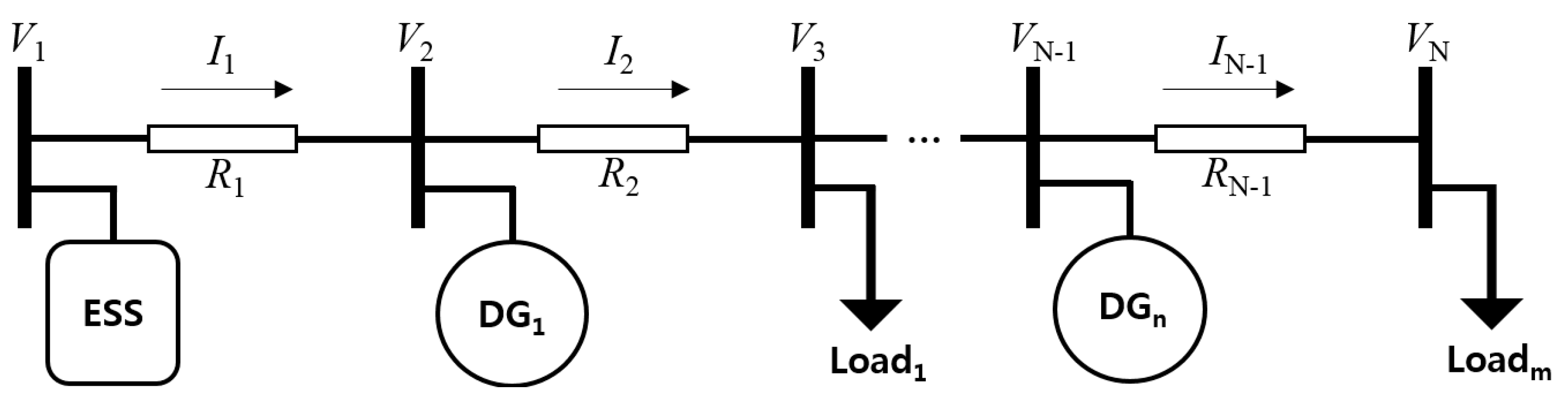
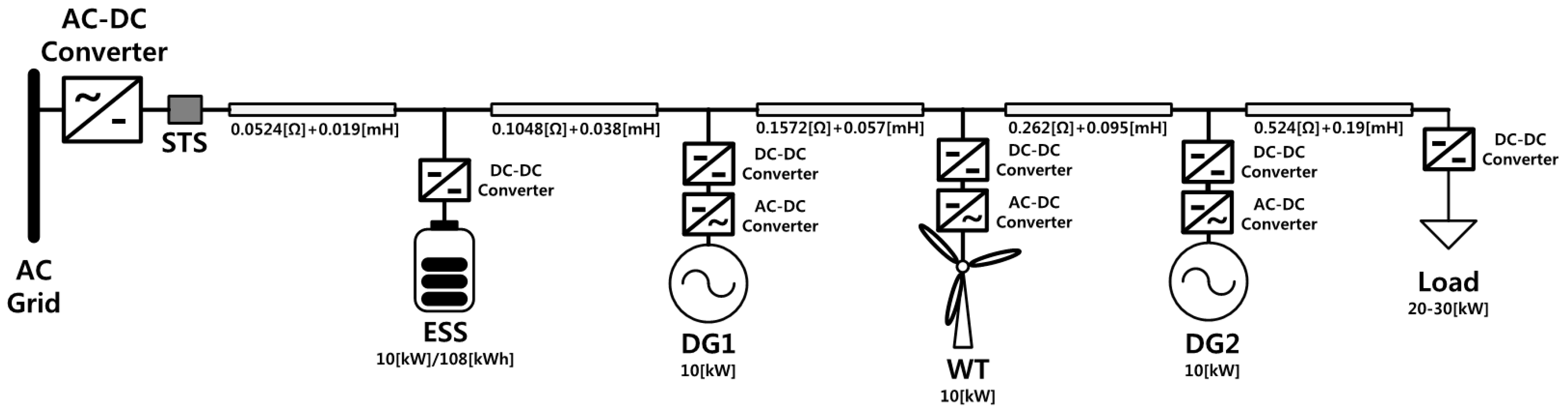
Figure 5 shows the configuration of the DC microgrid studied in this paper. The DC microgrid was modeled based on the experimental devices installed in Korea Electrotechnology Research Institute (KERI). It is made up of an AC-DC converter, static switch (STS), 10-kW/108-kWh ESS, two 10-kW DGs (dispatchable DG), one WT (non-dispatchable DG), load, and line impedance. The ESS and the load are connected to the DC microgrid with DC-DC converters and DGs are connected to the DC microgrid with AC-DC and DC-DC converters. The power rating of DC converters of the ESS, the WT, and the DGs is 10 kW. The power rating of load DC-DC converters is 30 kW. The nominal voltage of all DC-DC converters is 380/750 V (machine-side/grid-side). The nominal voltage of all AC-DC converters is 380 V for both AC and DC sides. The load was modeled as a variable resistor. The value of resistances and inductances of line are shown in Figure 5.
The DC distribution line consists of a bipolar topology with a nominal voltage of ±750 V. In this study, only the plus pole is used. The STS is constantly opened since this paper focuses on the islanded DC microgrid. One of the most important parameters to observe is change in the SOC. It takes few minutes to see change of the SOC, but the simulation time is tens of seconds. The SOC is barely changed in a time scale of tens of seconds, so the capacity of the battery is scaled down to 1/60 of its original value (108 kWh) to see change of the SOC clearly.
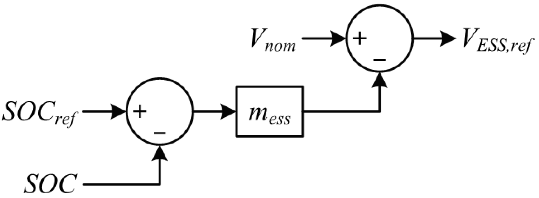
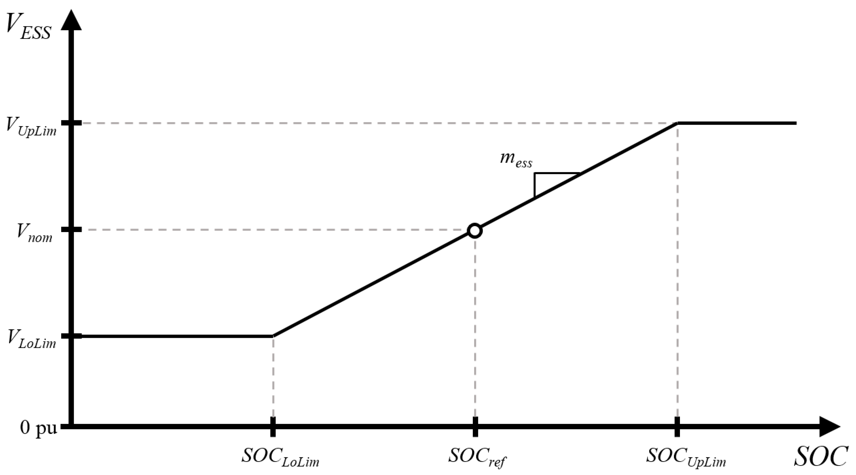
As mentioned in Section 2, SOCUpLim and SOCLoLim is arbitrarily determined as 0.9 and 0.3, respectively, and hence mess is 0.33 according to Equation (5). To calculate Vcomp, a day-ahead forecasted power and estimated output current are shown in Table 1. Since the nominal voltage of the DC grid is 750 V, the estimated current is simply acquired from the forecasted value divided by 750 V. Note that the WT power and the load can be changed instantaneously and the powers of DG1 and DG2 can also be changed due to the load change. These changes may cause an error while estimating the line voltage drop.
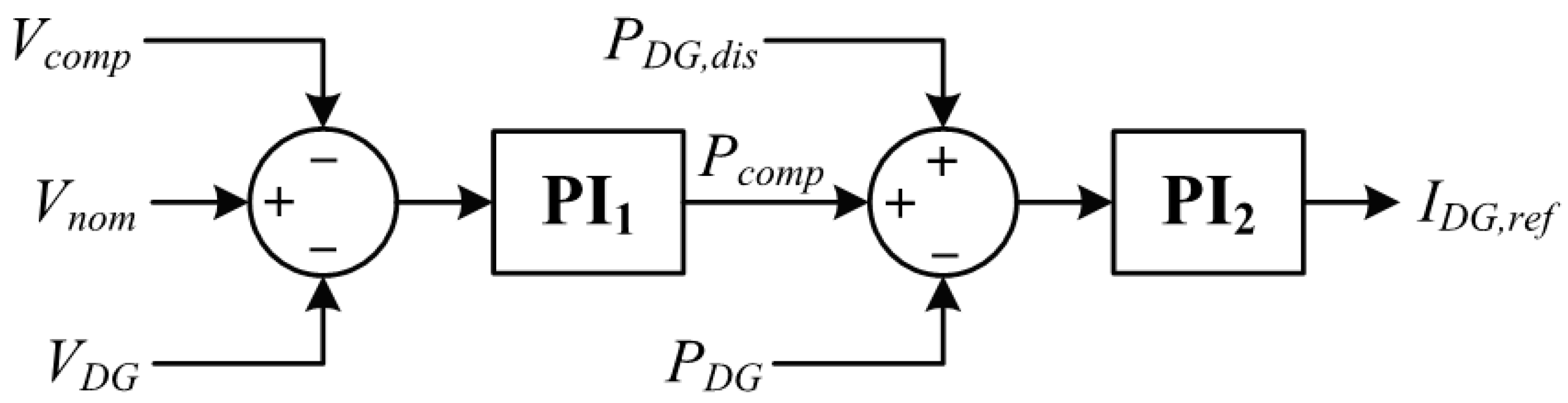
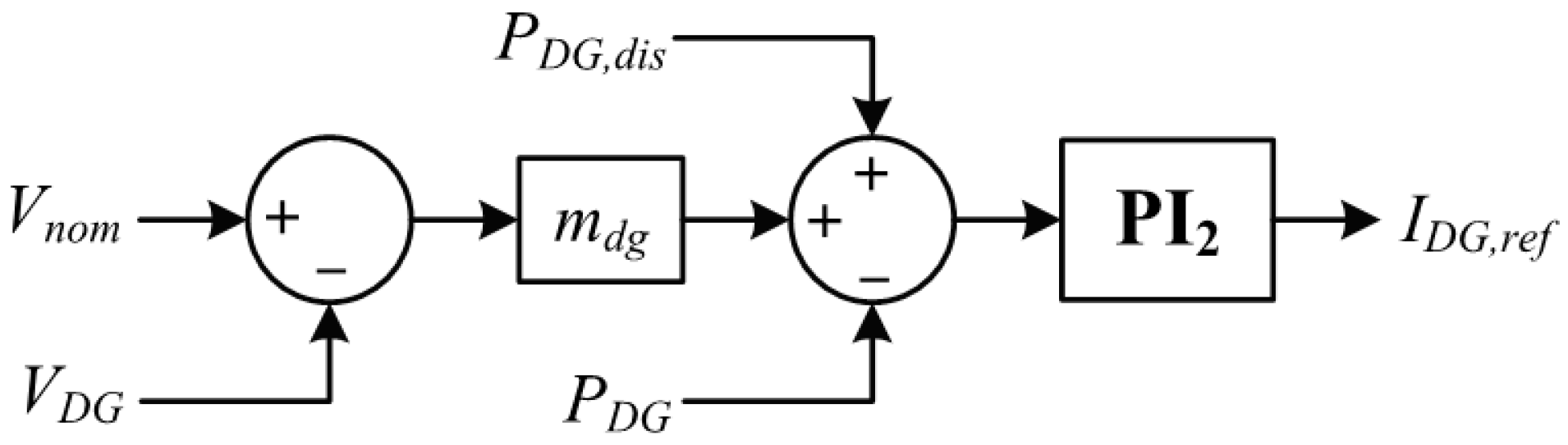
It is significantly important to carefully adjust the gain of PI1 for DG1 and DG2 because electrical distances from DGs to the load are different from each other. Since DG2 is located closer to the load than DG1, Pcomp (Figure 3) of DG2 must be greater than that of DG1 if the gain of PI1 for both DGs are same. To prevent this problem, the PI1 gain of DG2 is set greater than that of DG1 in this study. The proportional gain and the integral gain of DG1 are 10 and 100, respectively, and those of DG2 are 1 and 10, respectively. However, these gains are dependent on the location of DGs, amount of load variation, and network topology. Hence, it is difficult to precisely calculate the gain ratio among the DGs. In this study, the gains were determined by trial and error using simulation tests. The proportional and integral gains of PI2 for both DG1 and DG2 are 0.5 and 20, respectively.

4. Simulation Results and Discussion

Four different control methods including the proposed method were tested to prove the effectiveness of the proposed control method. Each control method is as follows:
  • Control method without droop (w/o Droop): The ESS is controlled to output constant voltage (nominal voltage) and the dispatchable DGs (DG1 and DG2) are controlled to output dispatched power only.
  • Voltage droop control method (V Droop): The voltage droop control shown in Figure 6 is applied to the DGs. The droop coefficient mdg is set to 3 in this study.
  • SOC-voltage droop and voltage droop control method (SOC-V Droop): SOC-voltage droop control shown in Figure 1 is applied to the ESS and the voltage droop control is applied to the DGs.
  • The proposed control method (Proposed): SOC-voltage droop control shown in Figure 1 is applied to the ESS and the control scheme shown in Figure 3 is applied to the DGs.
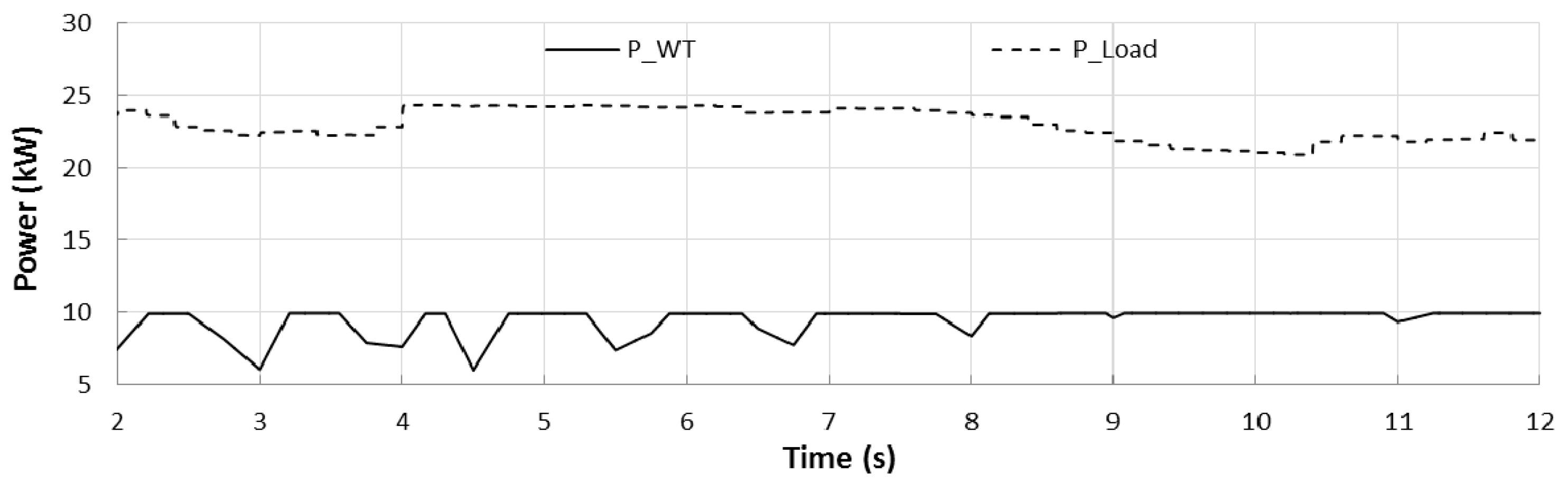
For all cases using different control methods, the output power of WT and the load is given as shown in Figure 7. The power of WT varies from 6 to 10 kW and the load varies from 21 to 24 kW. The power of WT used in this study was extracted from the wind speed measured by the KERI in July 2010 and it was the maximum wind speed measured. The maximum wind speed was over 11.5 m/s, which is the rated wind speed. In the simulation, the output power over 10 kW was limited by the limiter in the simulation library. Since the forecasted value of the WT power and the load are 9 kW and 23 kW, respectively, the error occurred while calculating Vcomp as mentioned in Section 2.
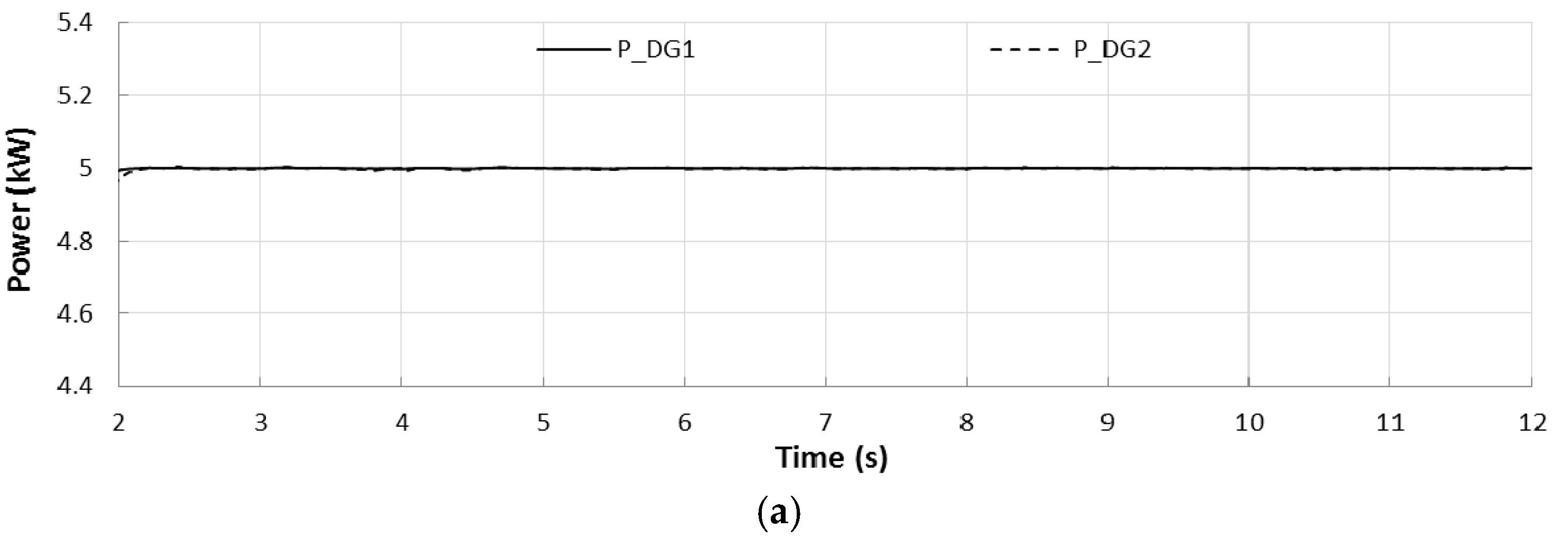
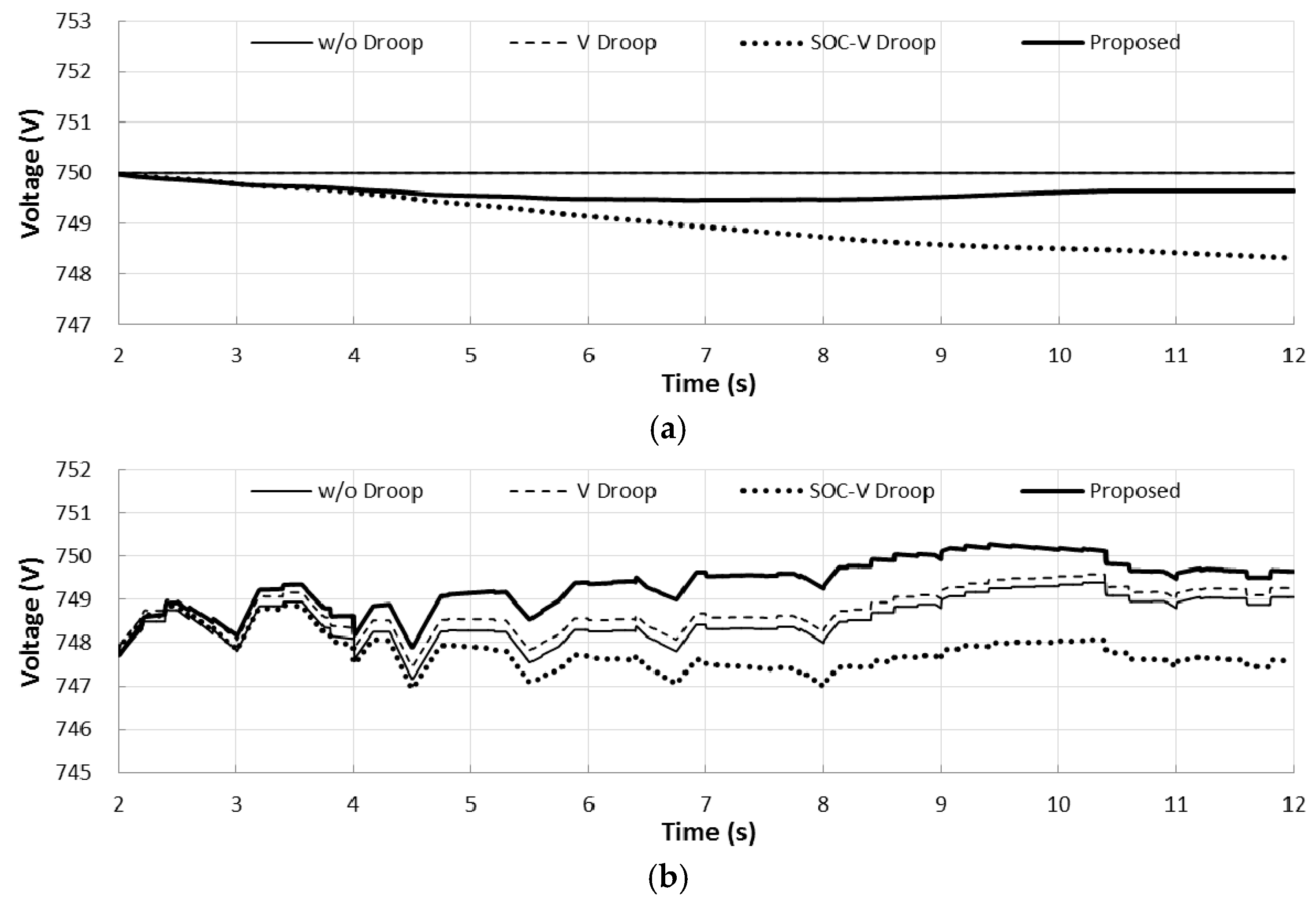
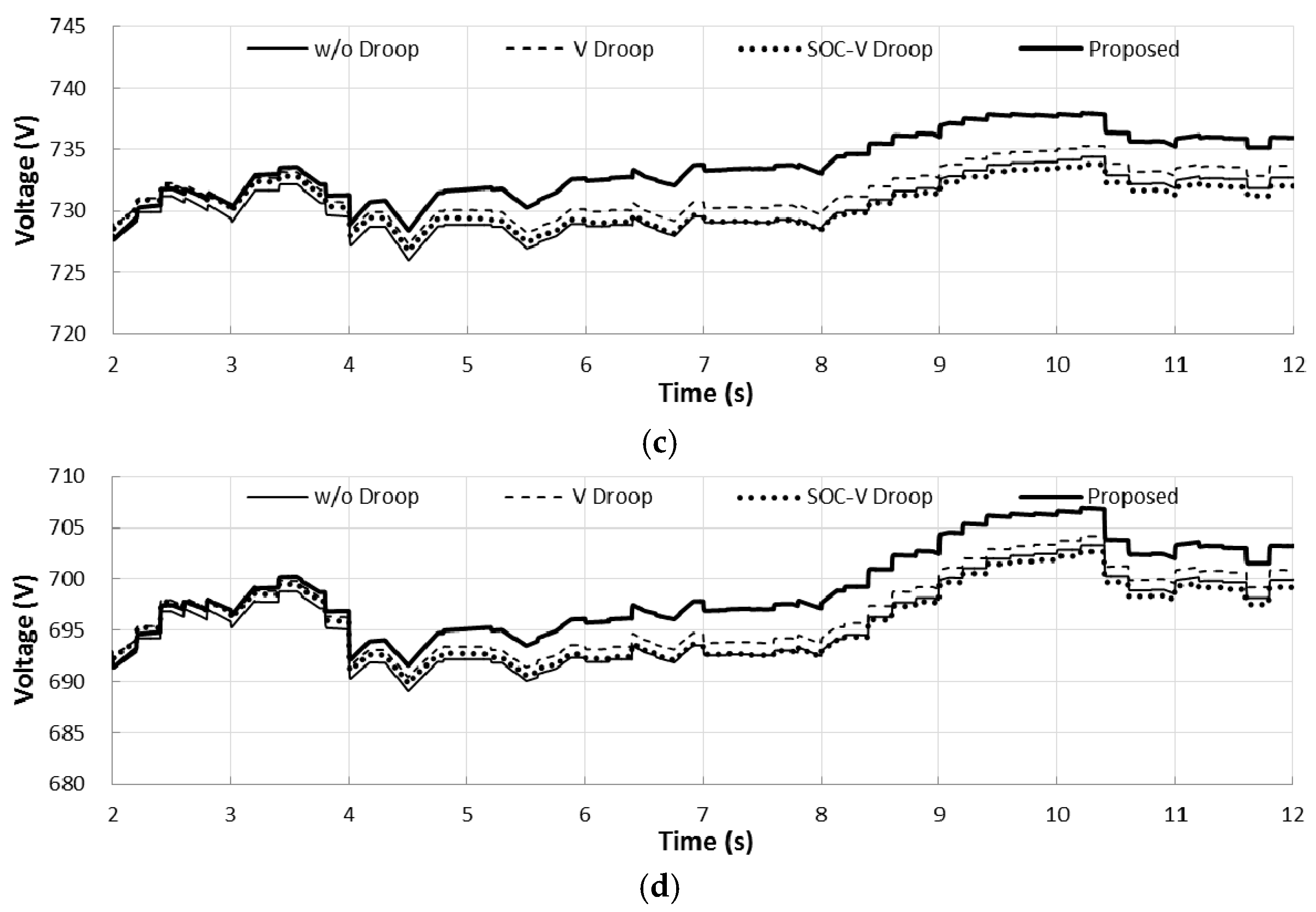
Figure 8 shows the output powers of DG1 and DG2 and Figure 9 shows voltages at the ESS bus, DG1 bus, DG2 bus, and the load bus. Figure 8a shows the output power of DGs without using droop method. Since both DGs are dispatched to output the same power (5 kW), they generate exactly the same amount of power. Even if the load and/or the WT power is changed, DGs do not support the voltage nor the SOC. However, the power sharing ratio among them can be maintained exactly as desired. 
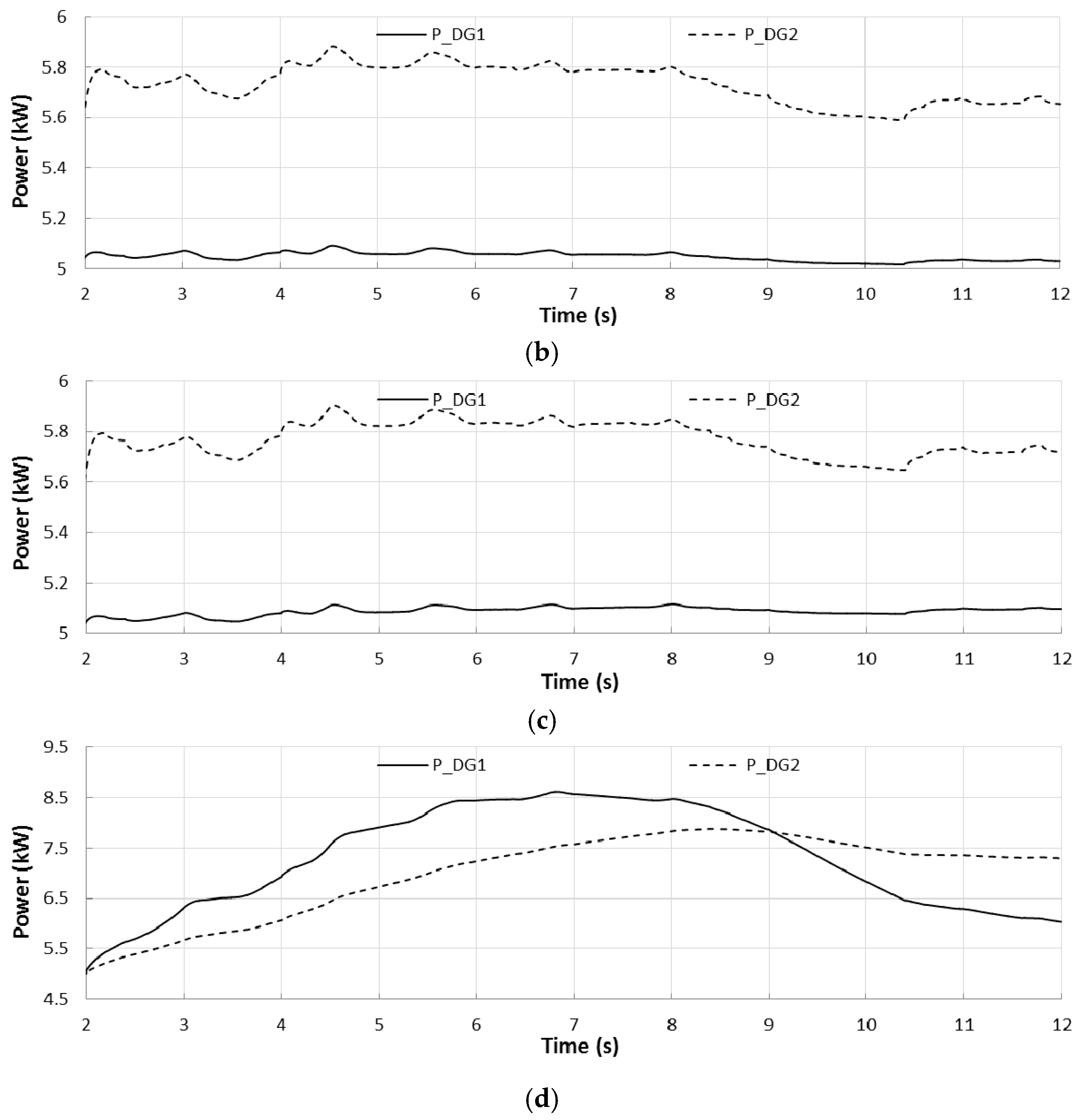
Figure 8b shows output of DGs using the voltage droop control method. Since DGs use voltage droop, they support the grid voltage and share power among them. DG2 injected more power than DG1 did because the voltage at DG2 (Figure 9c) is lower than the voltage at DG1 (Figure 9b). Figure 8c shows output of DGs using the SOC-voltage droop control method and it seems similar to Figure 8b since DGs adopted voltage droop control method for both cases. However, as shown in Figure 9a, the voltage of ESS was changed while using SOC-voltage droop in order to reflect the SOC change in the grid voltage, whereas it remained constant while using voltage droop control only. Due to applying SOC-voltage droop, DG1 and DG2 injected more power into the grid (see Figure 8c) than when applying voltage droop only (see Figure 8b). Figure 8d shows output powers of DGs using the proposed control method. The proposed control method is focused on the SOC recovery rather than precise power sharing ratio, and hence the output power of DG1 and DG2 are not same. Instead, their output power sharing ratio can be adjusted to some extent by tuning the gains of PI1 in Figure 3. For instance, the gains of DG located further from the load should be set larger than that of DG located closer to the load. DG1 and DG2 using the proposed method output more power than three other control methods to recover the SOC deviation. As shown in Figure 9, the bus voltages are closer to the nominal value (750 V) while using the proposed method than the cases of using the other three control methods.
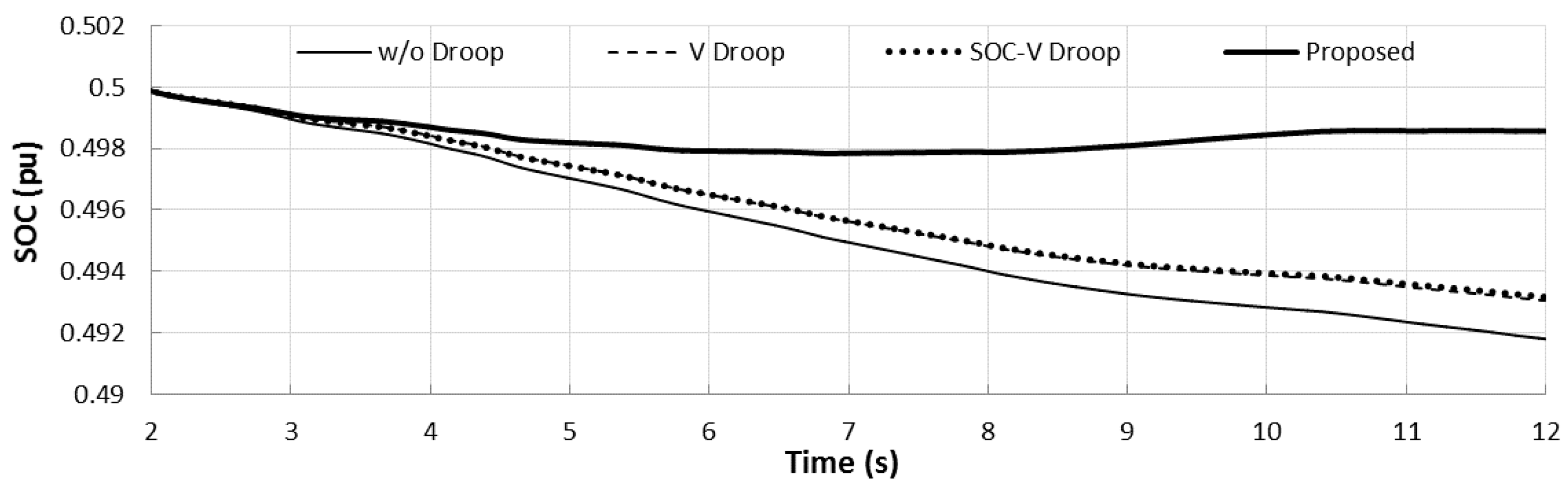
Figure 10 shows the SOC for four different control methods. The control method without droop cannot prevent SOC drop from the reference value (0.5 p.u. in this study) since it has no droop control. In the cases of “V Droop” and “SOC-V Droop”, the results are similar. However, the SOC is slightly closer to the reference value while using SOC-voltage droop than using voltage droop only. By using the proposed method, the SOC can be recovered drastically to the reference value as shown in Figure 10. Consequently, the simulation results show that it is feasible for DGs to acquire SOC information by measuring the grid voltage only, and hence the proposed method can recover the SOC in a decentralized way.

5. Conclusions

This paper presents a novel control method for the ESS and the dispatchable DGs in an islanded DC microgrid. Typically, the ESS is controlled as a voltage control mode (usually in a decentralized control method) or as a current control mode in a centralized way. In a centralized control, charging/discharging command is transmitted from a central controller (or EMS); however a centralized control method degrades the system reliability due to its dependency on communication systems. In a decentralized control using the ESS as a voltage control mode, the ESS follows the load change, so it should be charged by other dispatchable DGs. However, in a decentralized control method, other DGs cannot acquire the SOC data. To solve this problem, SOC-voltage droop control method is applied to the ESS and the SOC compensation control is applied to the dispatchable DGs. By adopting SOC-voltage droop control to the ESS, the SOC information can be reflected in the grid voltage. Due to the line voltage drop, the SOC deviation data cannot be sent to the dispatchable DGs accurately. Hence, the voltage drop compensation is calculated based on a day-ahead load/generation forecasted data. With the voltage drop value and the measured bus voltage, the dispatchable DGs calculate the power to be output to recover the SOC to the reference value. Even though the amount of power sharing among DGs changes due to the SOC recovering control, it can be adjusted to some extent by tuning the gains of controllers. The simulation results show that the proposed method (which is a decentralized control method) is effective from the perspective of maintaining the SOC close to the desired level.
Still, the SOC cannot be perfectly recovered to the reference value. This means further studies are needed in order to fully recover the SOC. Moreover, in this study, since the simulation includes many switch devices (AC-DC and DC-DC converters), it requires a lot of computational memory. Hence, a simulation time of over one minute cannot be examined by using this type of simulation study. Another type of simulation study, such as power flow calculation, should be implemented to analyze a one-day (24 h) simulation. The other issue for future works is the power sharing accuracy. As shown in Figure 8d, the power cannot be shared equally (or as desired). Hence, a proper power sharing method for the proposed control method should be developed as well. However, the proposed method can be used effectively for islanded DC microgrids with ESS controlled as a voltage source.

Acknowledgments

This work was supported by the Power Generation & Electricity Delivery Core Technology Program of the Korea Institute of Energy Technology Evaluation and Planning (KETEP) granted financial resource from the Ministry of Trade, Industry & Energy, Republic of Korea (No. 20143010011830).

Author Contributions

Chul-Sang Hwang conceived and designed the simulations; Eung-Sang Kim performed the simulations; Yun-Su Kim and Chul-Sang Hwang analyzed the data; Yun-Su Kim wrote the paper.

Conflicts of Interest

The authors declare no conflict of interest.

Nomenclature

Acronyms
ACAlternating current
BESSBattery energy storage system
DCDirect current
DGDistributed generation
EMSEnergy management system
ESSEnergy storage system
MPPTMaximum power point tracking
PIProportional-integral
PVPhotovoltaic
RESRenewable energy source
SOCState of charge
SOC-VState of charge-voltage
STSStatic switch
WTWind turbine
Energy Storage System
PESSOutput power of the energy storage system
Prate, Crate, IESS,rateRating power, capacity, current of the energy storage system
VESS, IESSOutput voltage and current of the energy storage system
messState of charge-voltage droop coefficient
VnomNominal value of the grid voltage
VUpLim, LoLimUpper and lower limits of the grid voltage
SOCi, SOCrefInitial and reference values of the state of charge
SOCUpLim, SOCLoLimUpper and lower limits of the grid voltage
Distributed Generation
PDG, PDG,disOutput and dispatched value of distributed generation active power
PcompActive power to compensate the state of charge deviation from the reference value
VcompCompensation voltage to compensate line voltage drop across the resistance between the ESS bus and the distributed generation bus
IDG,refReference output current of distributed generation
VDGVoltage at distributed generation bus
ILoadi,forcForecasted current of the load at bus i
IDGi,forcForecasted current of the distributed generation at bus i
VESS,estEstimated voltage of energy storage system output voltage
Microgrid
ViVoltage magnitude at bus i
IiCurrent flow from bus i to bus i+1
Ii,estEstimate current flow from bus i to bus i+1
RiResistance of line between bus i and i+1
NTotal number of the buses
nTotal number of the distributed generations

References

  1. Lu, D.D.C.; Agelidis, V.G. Photovoltaic-battery-powered DC bus system for common portable electronic devices. IEEE Trans. Power Electron. 2012, 24, 849–855. [Google Scholar] [CrossRef]
  2. Inamori, J.; Hoshi, H.; Tanaka, T.; Babasaki, T. 380-VDC power distribution system for 4-MW-scale cloud facility. In Proceedings of the IEEE 36th International Telecommunications Energy Conference, Vancouver, BC, Canada, 28 September–2 October 2014.
  3. Hammerstrom, D.J. AC versus DC distribution systems—Did we get it right? In Proceedings of the IEEE Power Engineering Society General Meeting, Tampa, FL, USA, 24–28 June 2007.
  4. Jeon, J.-Y.; Kim, J.-S.; Choe, G.-Y.; Lee, B.-K.; Hur, J.; Jin, H.-C. Design guideline of DC distribution systems for home appliances: Issues and solution. In Proceedings of the IEEE International Electric Machines and Drive Conference, Niagara Falls, ON, Canada, 15–18 May 2011.
  5. Shimomachi, K.; Hara, R.; Kita, H. Comparison between DC and AC microgrid systems considering ratio of DC load. In Proceedings of the IEEE PES Asia-Pacific Power and Energy Engineering Conference, Brisbane, Australia, 15–18 November 2015.
  6. Whaite, S.; Grainger, B.; Kwasinski, A. Power quality in DC power distribution systems and microgrids. Energies 2015, 8, 4378–4399. [Google Scholar] [CrossRef]
  7. Electric Power Research Institute (EPRI). DC Power Production, Delivery and Utilization; EPRI: Palo Alto, CA, USA, 2006. [Google Scholar]
  8. Olivares, D.E.; Mehrizi-Sani, A.; Etemadi, A.H.; Canizares, C.A.; Iravani, R.; Kazerani, M.; Hajimiragha, A.H.; Gomis-Bellmunt, O.; Saeedifard, M.; Palma-Behnke, R.; et al. Trends in microgrid control. IEEE Trans. Smart Grid 2014, 5, 1905–1919. [Google Scholar] [CrossRef]
  9. Xiao, J.; Wang, P.; Setyawan, L. Multilevel energy management system for hybridization of energy storage in DC microgrids. IEEE Trans. Smart Grid 2016, 7, 847–856. [Google Scholar] [CrossRef]
  10. Chen, Y.-K.; Wu, Y.-C.; Song, C.-C.; Chen, Y.-S. Design and implementation of energy management system with fuzzy control for DC microgrid systems. IEEE Trans. Power Electron. 2013, 28, 1563–1570. [Google Scholar] [CrossRef]
  11. Karavas, C.S.; Kyriakarakos, G.; Arvanitis, K.G.; Papadakis, G. A multi-agent decentralized energy management system based on distributed intelligence for the design and control of autonomous polygeneration microgrids. Energy Convers. Manag. 2015, 103, 166–179. [Google Scholar] [CrossRef]
  12. Kyriakarakos, G.; Piromalis, D.D.; Dounis, A.I.; Arvanitis, K.G.; Papadakis, G. Intelligent demand side energy management system for autonomous polygeneration microgrids. Appl. Energy 2013, 103, 39–51. [Google Scholar] [CrossRef]
  13. Lie, X.; Chen, D. Control and operation of a DC microgrid with variable generation and energy storage. IEEE Trans. Power Deliv. 2011, 26, 2513–2522. [Google Scholar]
  14. Fu, Y.; Zhang, Z.; Wang, Y.; Yu, M.; Hei, Y.; Meng, J.; Wang, H. Research on power coordinated control of wind turbine-based DC microgrid under various modes. In Proceedings of the 2016 IEEE 8th IPEMC-ECCE Asia, Hefei, China, 22–26 May 2016; pp. 1480–1484.
  15. Papadimitriou, C.N.; Kleftakis, V.A.; Rigas, A.; Hatziargyriou, N.D. DC-microgrid control strategy using DC-bus signaling. In Proceedings of the MedPower, Athens, Greece, 2–5 November 2014.
  16. Dragicevic, T.; Guerrero, J.M.; Vasquez, J.C.; Skrlec, D. Supervisory control of an adaptive-droop regulated DC microgrid with battery management capability. IEEE Trans. Power Electron. 2014, 29, 695–706. [Google Scholar] [CrossRef]
  17. Gao, L.; Liu, S.; Dougal, R.A. Dynamic lithium-ion battery model for system simulation. IEEE Trans. Compon. Packag. Technol. 2002, 25, 495–505. [Google Scholar]
  18. Kumar, P.; Singh, A.K. Grid Codes: Goals and Challenges. In Renewable Energy Integration, 1st ed.; Hossain, J., Mahmud, A., Eds.; Springer: Singapore, 2014; pp. 17–39. [Google Scholar]
  19. Saft Inc. Lithium-ion Battery Life Technical Sheet; Saft Inc.: Bagnolet, France, 2014. [Google Scholar]
Figure 1. Control scheme of energy storage system output voltage.
Energies 09 01070 g001
Figure 2. SOC-voltage droop for ESS control.
Energies 09 01070 g002
Figure 3. Control scheme of dispatchable distributed generation output current.
Energies 09 01070 g003
Figure 4. Single-line diagram of an islanded DC microgrid.
Energies 09 01070 g004
Figure 5. Single-line diagram of the DC microgrid.
Energies 09 01070 g005
Figure 6. Conventional voltage droop control method for DGs.
Energies 09 01070 g006
Figure 7. Output power of wind turbine and load.
Energies 09 01070 g007
Figure 8. Output powers of DG1 and DG2 using: (a) without droop method; (b) voltage droop method; (c) SOC-voltage and voltage droop method; and (d) the proposed method.
Energies 09 01070 g008aEnergies 09 01070 g008b
Figure 9. Voltages at: (a) ESS bus; (b) DG1 bus; (c) DG2 bus; and (d) load bus.
Energies 09 01070 g009aEnergies 09 01070 g009b
Figure 10. Output power of WT and load.
Energies 09 01070 g010
Table 1. Forecasted/Estimated power and current of DGs and load.
DG/LoadForecasted Power (kW)Estimated Current (A)
DG156.67
DG256.67
WT912
Load2330.67

