1. Introduction
With the increasing use of technology, the demand for energy is surging at an unprecedented rate [
1]. This offers significant opportunities to save energy and protect the environment [
2]. Internal combustion engines (ICEs) are the major source of mobile power in the world, and will likely continue to be for some decades [
3]. However, on average, two-thirds of the energy obtained from the fuel used is still wasted through exhaust gases and coolants and lost in the form of heat [
4,
5]. Recovering this wasted energy, particularly energy wasted through exhaust is, therefore, of great significance [
6,
7]. There are several technologies for the recovery of wasted energy from an ICE [
8]. One solution is to integrate a waste heat recovery system based on a Rankine cycle [
9,
10,
11,
12] into the engine, which this paper addresses.
In the 1970s, the idea of recovering waste heat from automotive ICEs using the Rankine cycle was conceived [
13]. However, the idea was discarded owing to its mechanical complexity and the loss in power-to-weight ratios that would inevitably result. Today, many researchers recognize that recovering waste heat from engine exhaust has the potential to decrease fuel consumption without increasing emissions, and recent advances in technology have made these systems viable and cost effective [
14]. Many researchers have concluded that the Rankine cycle system is highly effective in recovering waste heat from ICEs [
15,
16,
17]; thus, research in this area has become significant worldwide. Hajabdollahi et al. [
18] built a model of a Rankine cycle system for diesel engine waste heat recovery and analysed the thermal efficiency and total annual cost of the system. Gunnar et al. [
19] discussed experimental results and practical challenges while utilizing a waste heat recovery system in the exhaust gas recirculation system of a truck engine. Zhang et al. [
20] designed an integrated Rankine cycle system and used a screw expander to recover waste heat from a diesel engine. When the diesel engine operated at 250 kW, the output power of the single screw expander was 10.38 kW.
In the waste heat recovery system of a Rankine cycle system, one of the key parts is the expander, which has an important influence on system performance. There are many types of expanders for a Rankine cycle system [
21]. Vane expanders are likely choices because they can provide high expansion ratios and acceptable performance over a wide range of operations with a simple design and low cost. In addition, it is relatively easy to scale them down over a wide range of 1–10 kW. The rotary vane expander is a good option when the required power output is lower than 2 kW [
22]. Kolasinski et al. conducted experimental and numerical analyses on a rotary vane expander used in a micro-organic Rankine cycle (micro-ORC) system. The experimental results showed that the rotary vane expander could be adopted in micro-ORC systems if its sealing and bearing issues were solved [
23].
Gnutek et al. analysed the use of a vane rotary expander with a low-boiling working fluid for small-capacity ORC systems. The experimental results revealed that the system could generate approximately 1.2 kW, which was equivalent to approximately 10% of the net conversion efficiency. Moreover, the experiment proved that the ORC system power and efficiency are dependent on the working fluid mass flow [
24].
The turbo expander, which is widely used in industrial power generation, is not suitable for cases with a small gas flow rate because its miniaturization results in reduced efficiency and increased cost. Large-scale systems above approximately 50 kW employ turbo expanders because of their relatively high expansion efficiency at higher power ratings [
25]. When the power is below 50 kW, the performance of turbo expanders begins to deteriorate until unacceptable efficiencies are reached at 10 kW [
26]. Moreover, their units are very expensive and their reliability has yet to be proven [
27,
28].
However, a piston expander has higher thermal efficiency under low steam-flow-rate conditions and a good power output/size ratio. This type of expander is generally built or renovated based on existing commercial IC engines [
29,
30,
31,
32,
33,
34]. Endo et al. [
35] studied a piston expander used in a Rankine cycle system to recover waste heat from hybrid electric vehicle exhaust. In this study, the use of a recovery device increased the overall recovery system efficiency from 28.9% to 32.7%. Yulia et al. [
36] proposed a steady-state semi-empirical model to study the performance of a piston expander. The results indicated that the piston expander has relatively high entropy and mechanical efficiency and is suitable for engine waste heat recovery. Chiong et al. [
37] used a nozzle piston expander instead of a conventional expander to recover exhaust energy. Simulation results showed that the nozzle piston expander could increase output power from a minimum of 0.73 kW to a maximum of 4.75 kW, and has the potential to improve engine system level efficiency.
The single-valve expander is a type of piston expander. Due to its reliability, simple structure, and high compression ratio, this type of piston expander has been widely used in compressed-air energy storage systems and small cooling equipment. However, it has not yet been used in engine waste heat recovery systems. Therefore, in this study, a single-valve piston expander is applied to a waste heat recovery system and is tested to assess system performance using several indices. In addition, an optimization method is proposed.
3. Experimental Results and Analysis
In a waste heat recovery system, the output power of the expander is closely related to the running state of the engine. Variations in engine speed and load will vary the heat of the exhaust, resulting in steam pressure and temperature variations in the expander, thereby affecting the expander speed and output power. In this experiment, four conditions (listed in
Table 4) of the gasoline engine are chosen to evaluate the waste heat recovery performance.
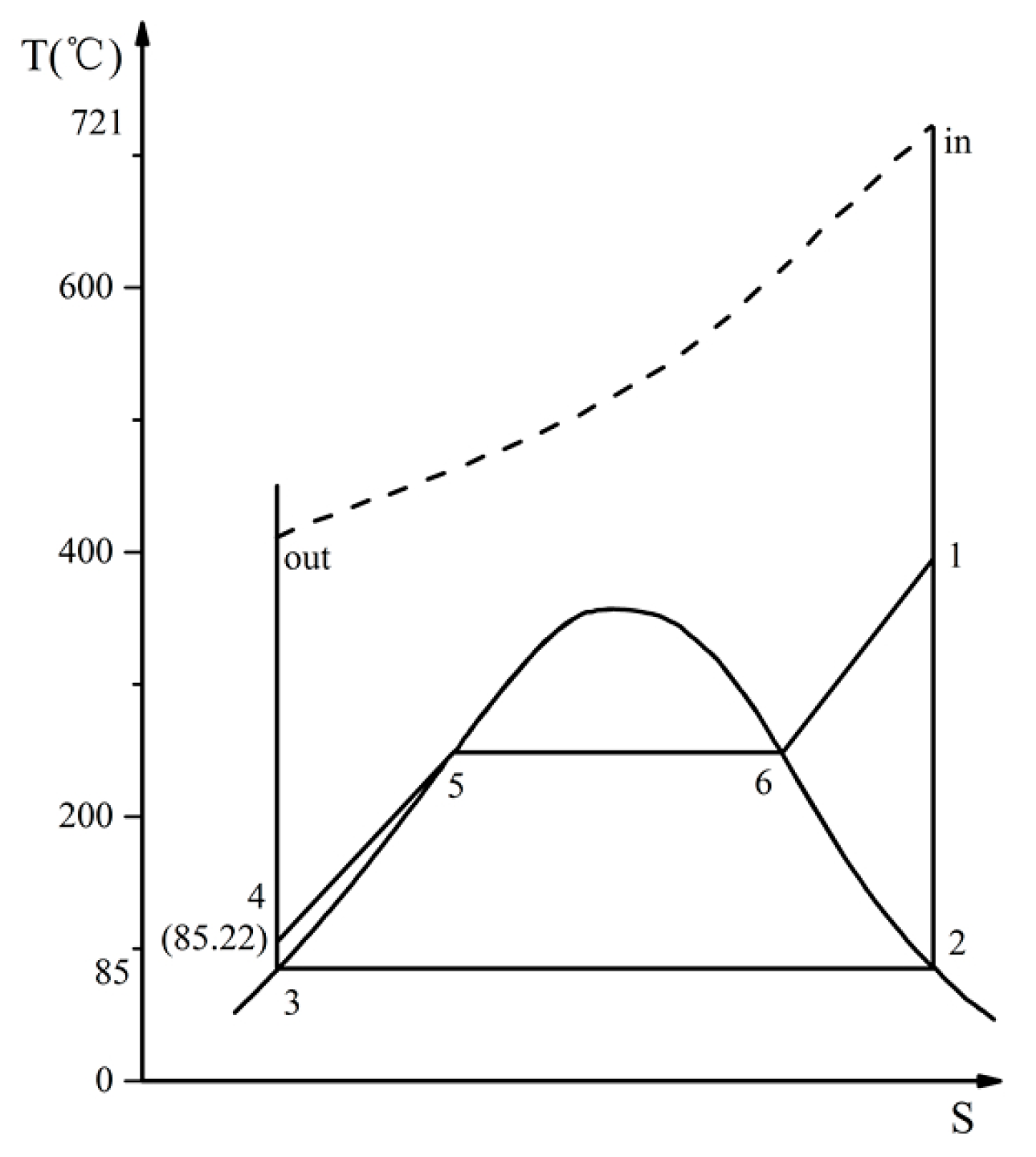
Figure 3 shows a T-S diagram of the Rankine cycle for case 1.
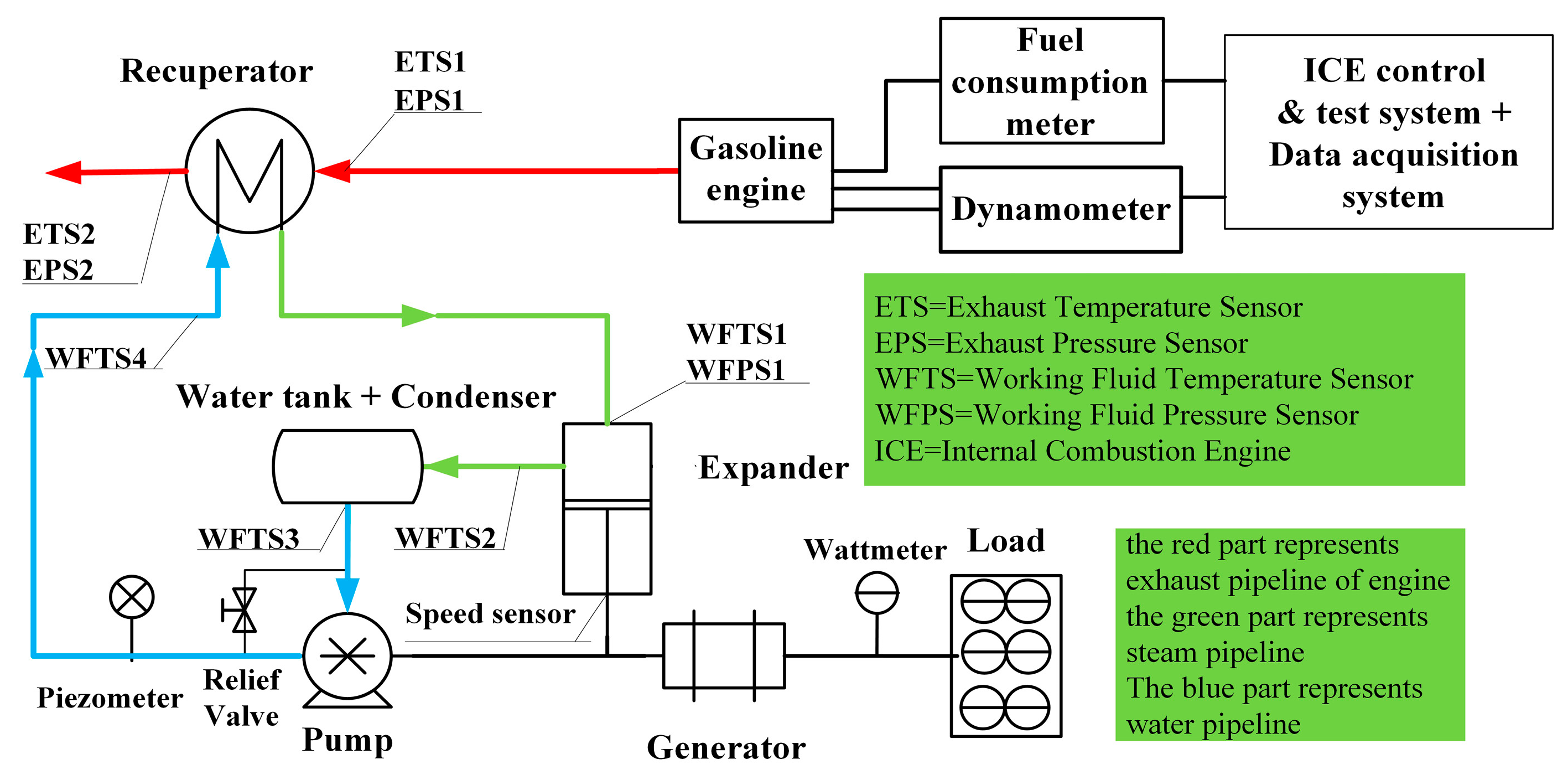
3.1. Recuperator Influence on the Gasoline Engine
Variations in the operating state of the engine will affect the output power of the waste heat recovery system, and the recuperator in the exhaust tube has an impact on the back pressure of the exhaust gas. If the exhaust gas back pressure is too high, it will decrease the power of the engine; thus, both the back-pressure and exhaust temperature are measured. The measurement results are shown in
Figure 3.
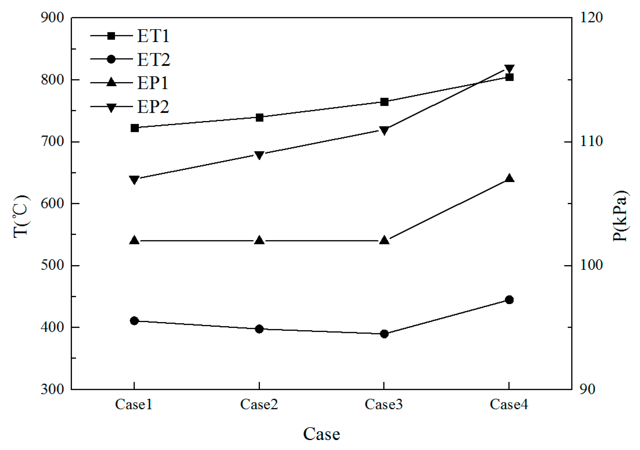
As can be seen in
Figure 4, the drops in exhaust temperature between the recuperator inlet (ET1) and outlet (ET2) are remarkable, reaching 300–380 °C. The recuperator in the exhaust tube increased the back-pressure by a maximum of 9.4 kPa for all four conditions. In addition, test results for fuel consumption are listed in
Table 5. The fuel consumption only increased by 0.20% when the recuperator was present in the exhaust tube.
3.2. Performance of Expander and Recovery System
The pressure sensors installed in the expander cylinder head can measure the pressure variation with a crank angle and obtain an indicator diagram, as shown in
Figure 5. This diagram indicates how the expander cylinder pressure changes with the crank angle and volume when the engine is operating as per Case 4 (76.6 kW, 5500 r/min).
Based on the indicator diagram, the powers of the four test cases can be calculated. They are 2.23, 2.63, 3.44, and 5.06 kW, respectively. As generator power and efficiency were measured, the shaft power of the expander can be calculated, which are 2.06, 2.45, 3.24, and 3.47 kW for the four test cases, respectively.
3.3. Performance Analysis of Waste Heat Recovery System
Several parameters are used to evaluate the performance of the experimental system in recovering waste heat.
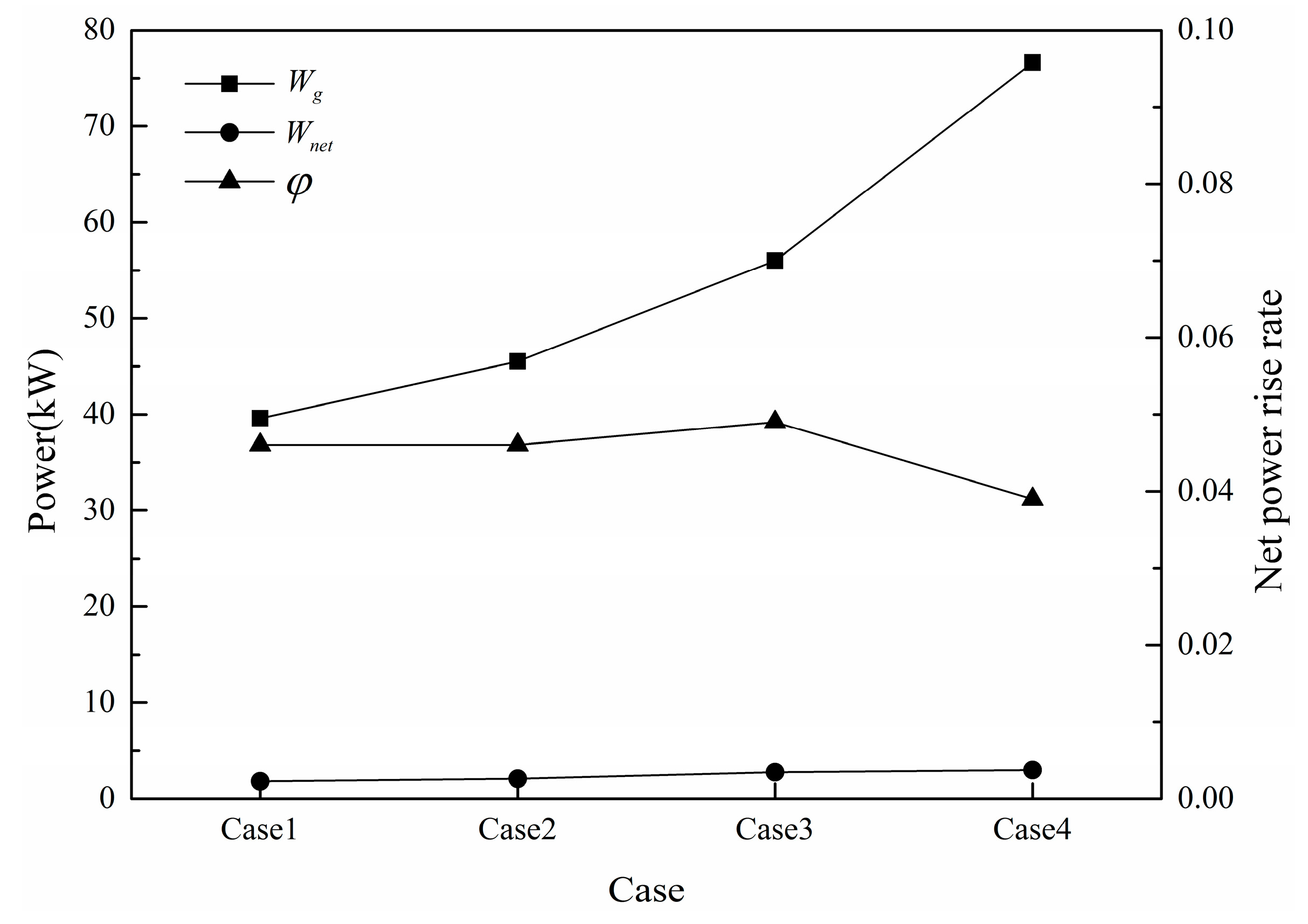
3.3.1. Net Power Rise Rate
One metric to evaluate the recovery capacity of the test system is
, which is defined as the rise ratio of the power:
where
is the gasoline engine power.
is the expander output power.
is the shaft power of the expander calculated according to the generator efficiency and electrical power, and
is the plunger pump consumption power. As the pump is driven by the expander, the shaft power
is equal to expander power
minus pump power
.
is the gasoline engine power loss owing to pressure loss resulting from the recuperator located in the exhaust system. As shown in
Figure 6, when the gasoline engine is operating at 4000 r/min and 56 kW, the energy recovered from the exhaust increases the total power of the system by 2.74 kW, which is equivalent to 4.9% of the engine power.
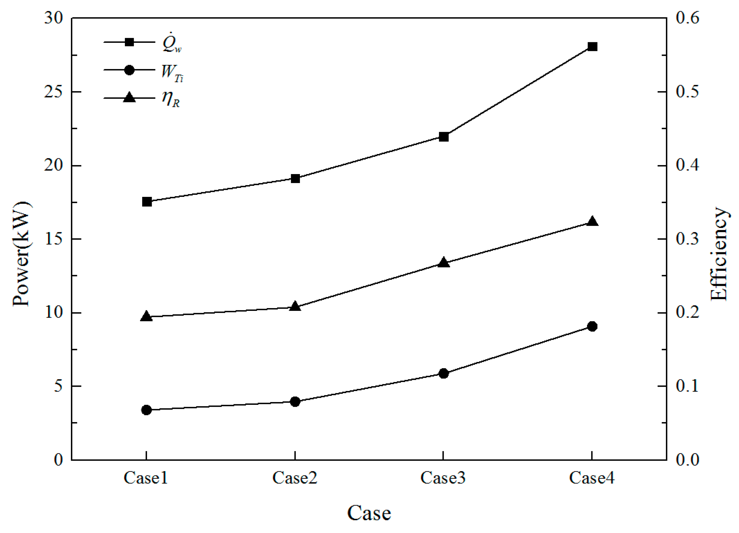
3.3.2. Thermal Efficiency of Rankine Cycle
The thermal efficiency of the Rankine cycle,
, is defined to evaluate the cycle’s capacity to convert heat into work:
where
is the ideal indicated power of the expander, and
is the theoretical mass flow rate of the working fluid, which is calculated using a thermodynamic model of the piston expander [
39].
is the mass flow rate of the working fluid, which is measured in the experiment.
and
are, respectively, the specific enthalpy of the working fluid at the inlet and outlet of the expander.
is the specific enthalpy of the working fluid at the inlet of the recuperator.
is the energy absorbed by the working fluid from the exhaust gas.
As shown in
Figure 7, the thermal efficiency of the Rankine cycle system increases from 19.45% to 32.33% along with an increase in the power of the engine.
3.3.3. Overall Combined Cycle System Efficiency
where
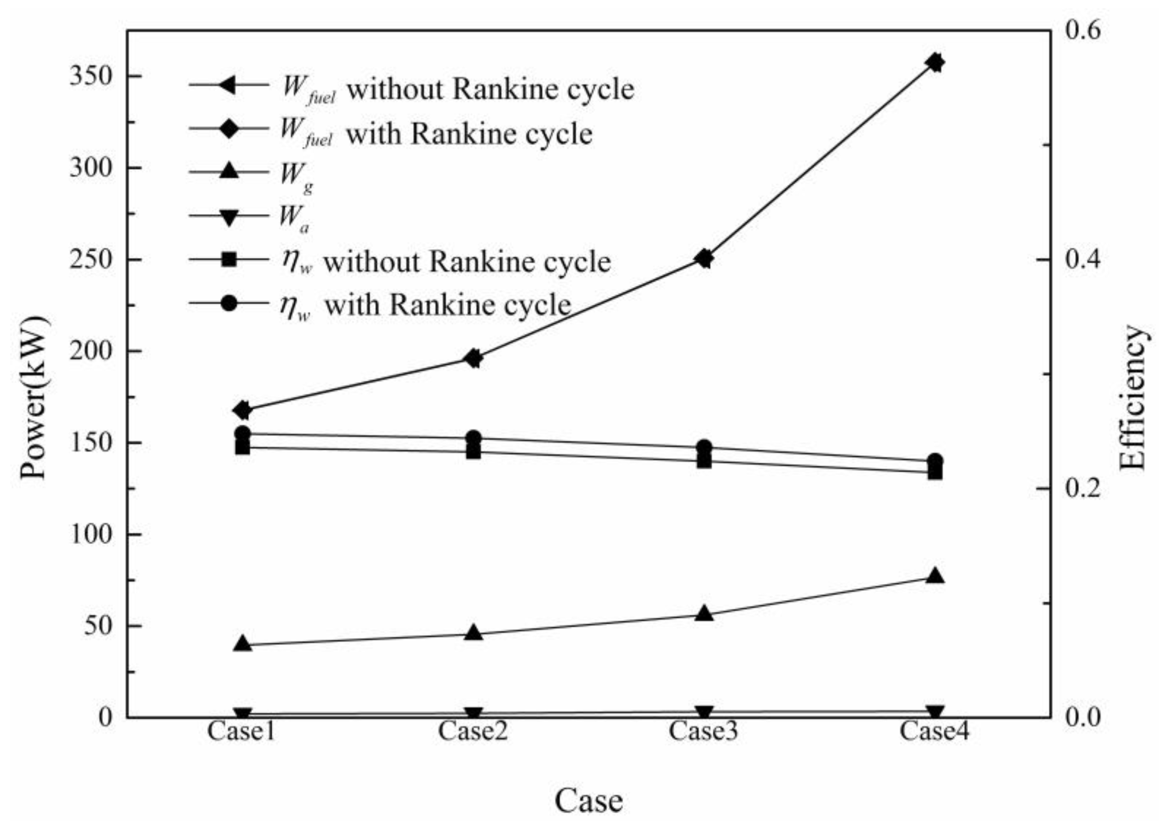
is the fuel heat. As shown in
Figure 8, when the gasoline engine power is 45.5 kW, the original efficiency of the engine is 23.2%. However, when the exhaust energy was extracted by the expander, the overall combined cycle system efficiency reached 24.4%. Approximately 1.2% of the total fuel energy was recovered. For an additional weight of 50 kg, the propulsive power increase is of about 0.7% at 3500 RPM and reaches 1.25% at 1000 RPM [
40]. In this recovery system, the weight of the equipment is below 50 kg, and the gasoline engine speed is in 4000 RPM or above. The increase of propulsive power will be less than 0.7%. Thus, the fuel economy efficiency increased by nearly 1%.
4. Analysis of Potential Power Increase of the Expander
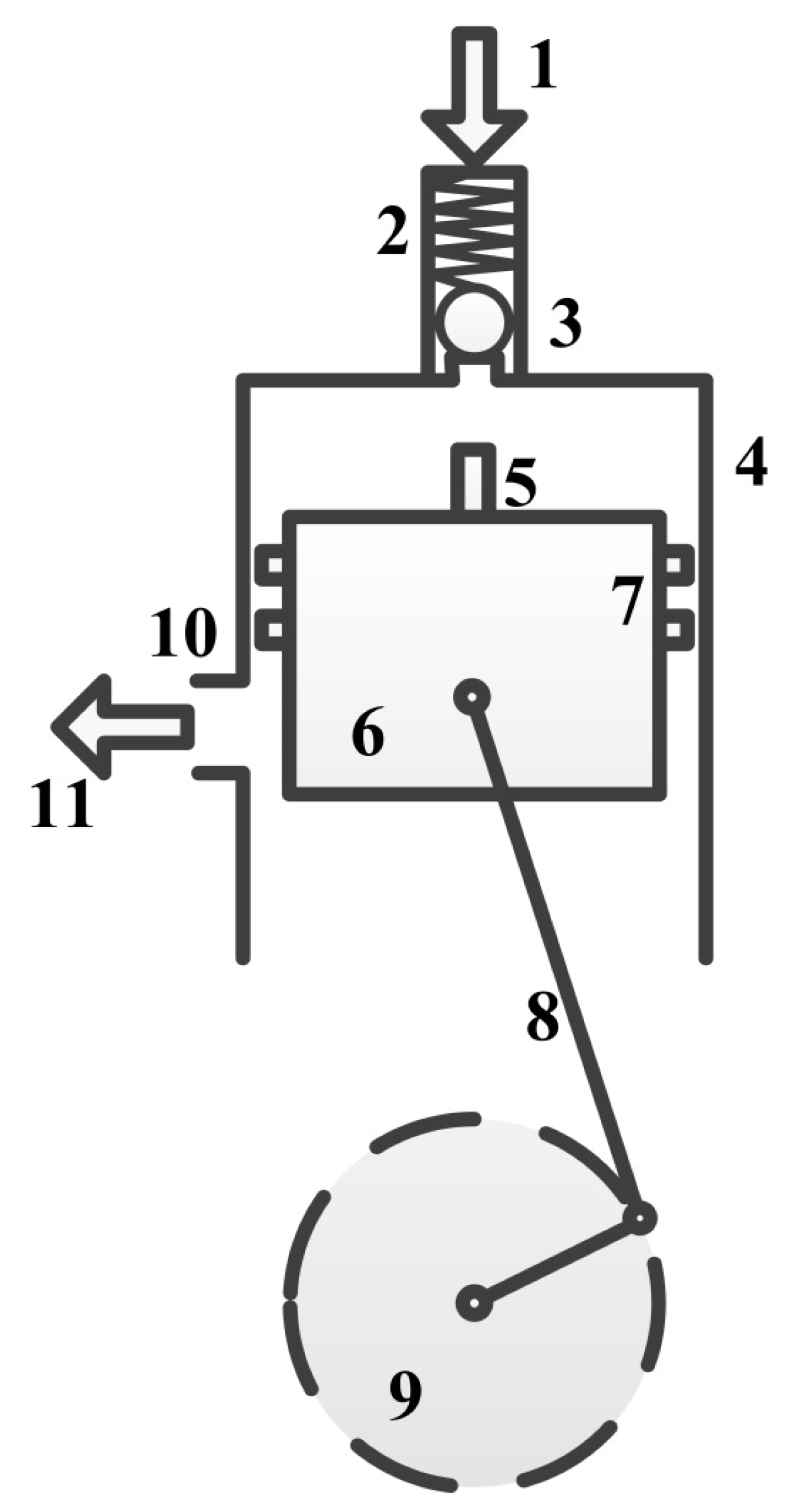
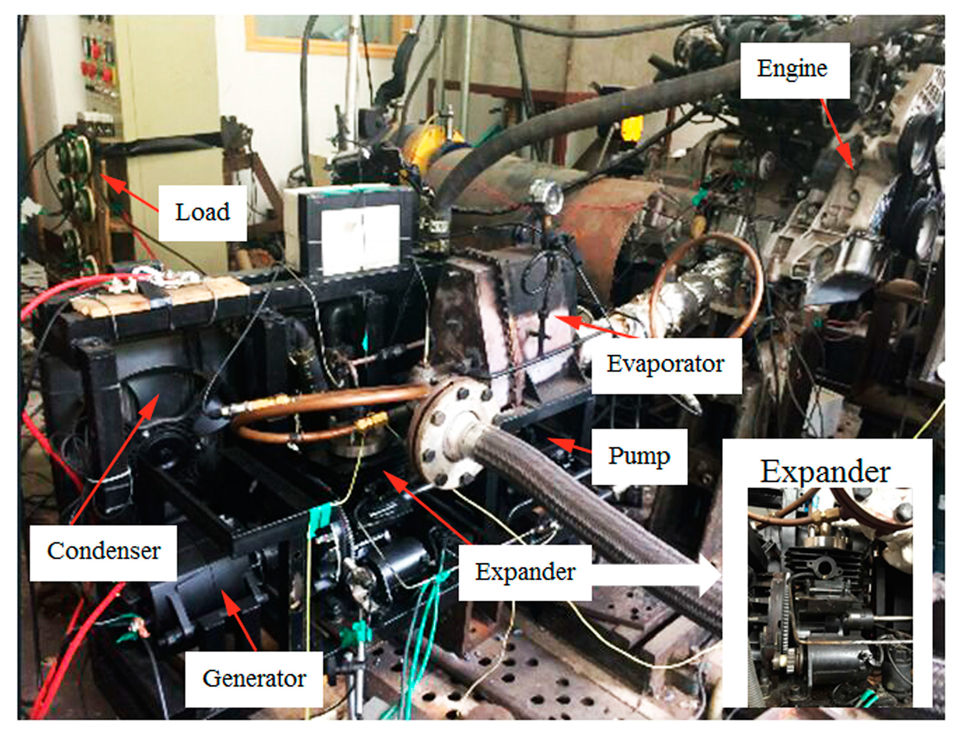
The expander recovery system used in the above theoretical and experimental research is shown in
Figure 9. When the piston moves toward the top dead point, the push rod drives the ball valve open. With the inlet valve open, high-pressure steam enters and fills the cylinder. When the piston reaches the top dead point, the inlet valve is fully open. Then, the piston performs a down stroke as the inlet valve remains open, allowing steam to fill the cylinder until the inlet valve closes.
With the inlet valve closed, expansion follows, pushing the piston away from the cylinder head. The linear thrust acting on the piston end of the connecting rod is transmitted to the crankshaft, providing rotary movement. When the piston nears the bottom dead point, the exhaust port opens, and the steam in the cylinder discharges from the exhaust port. Then, the piston moves up to compress the remaining steam until the intake valve opens again to perform the next cycle.
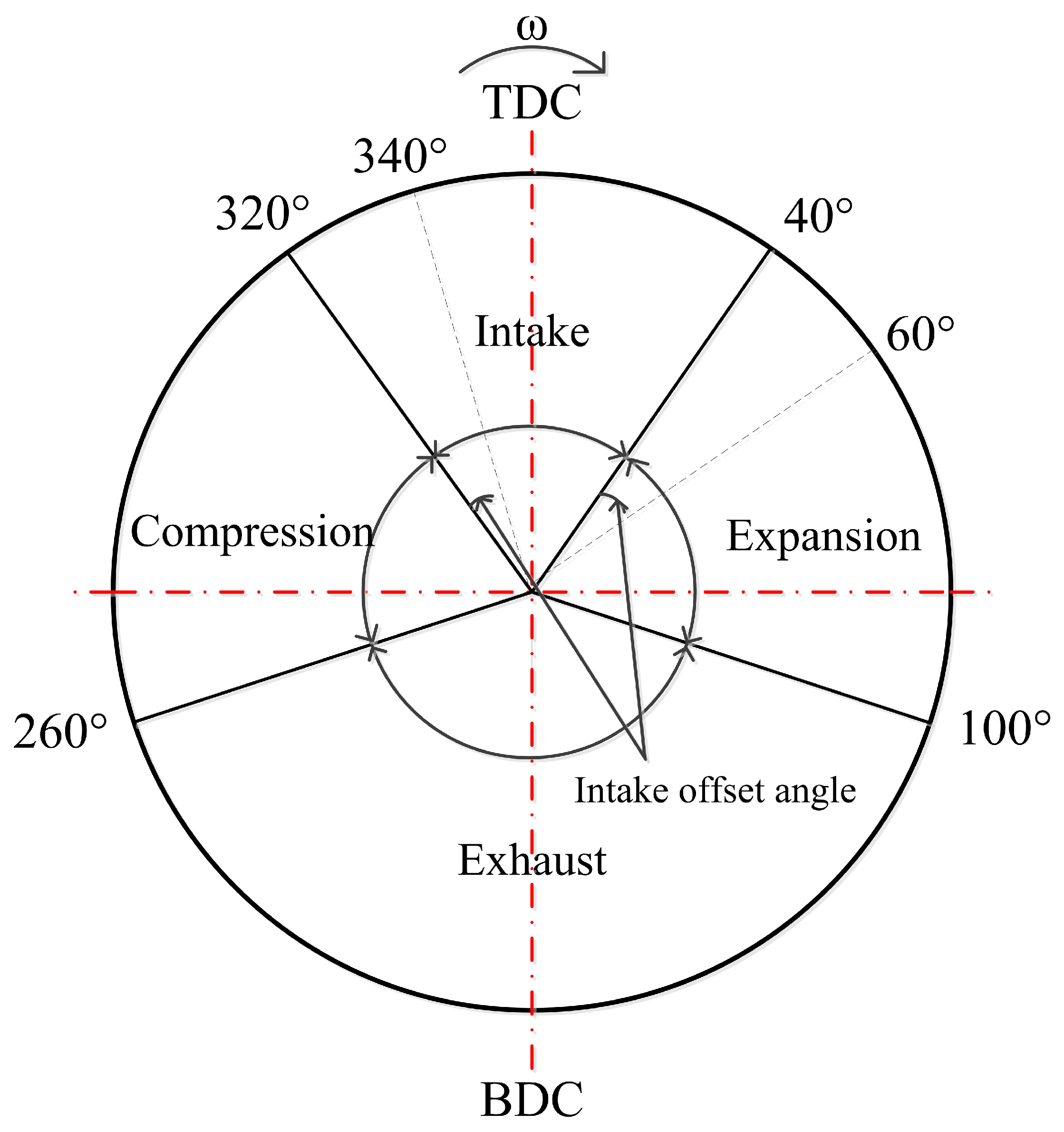
In the expander, the intake valve opens at 40° before TDC (Top dead centre) and closes at 40° after TDC, as shown in
Figure 10. This implies that the intake valve opens, and high-pressure steam fills the cylinder relatively early during the piston’s upstroke, leading to a relatively large negative power. If the intake valve opens later, the power of the expander will be increased for the same intake valve lift-and-open period. In order to analyse the influence of the open timing of the intake valve on the expander performance, several analyses were conducted.
The offset angle is defined as the change in the angle at which the intake valve opens from its initial open angle. In this study, the initial intake phase occurs during the 320°–40° TDC period, and the exhaust phase is in the 100°–260° BDC (Bottom dead centre) period, as shown in
Figure 10. If the intake valve opens later than the original open point, the offset angle is considered positive. If it opens earlier, the offset angle is negative. When the intake valve opens too early, the cylinder may reach maximum pressure before TDC; this will result in negative compression work, reducing the output power and efficiency of the expander.
In this section, a thermodynamic model of the piston expander, built using MATLAB/Simulink (R2014a, MathWorks, Natick, MA, USA, 2014), is described [
41]. This model consists of energy conservation, mass conservation, and heat transfer equations. The state parameters of the working fluid in the system are calculated by a function called REFPROP (v9.0, National Institute of Standards and Technology, Gaithersburg, MD, USA), which is part of NIST (National Institute of Standards and Technology) software. It is used to analyse the influence of the intake phase on expander performance.
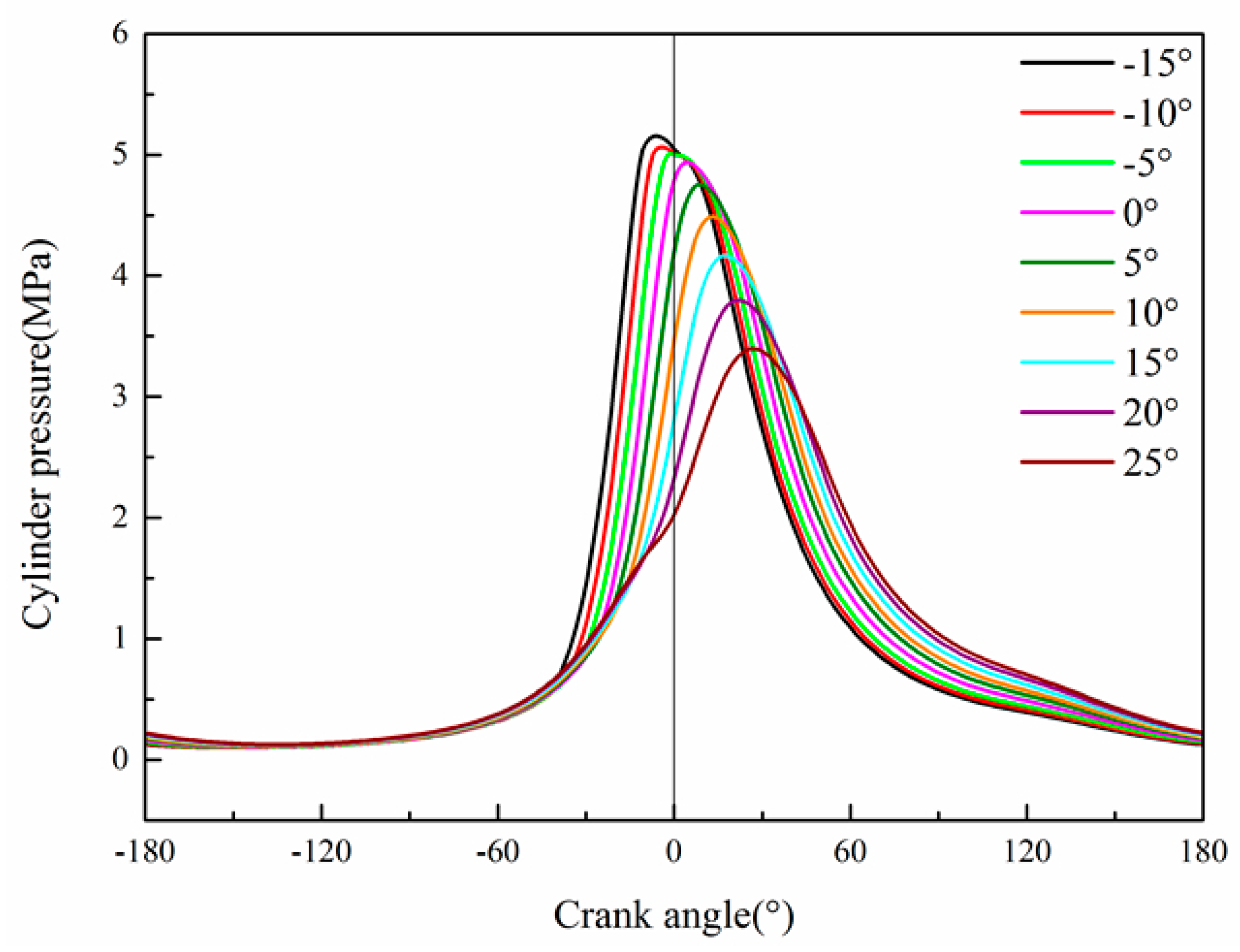
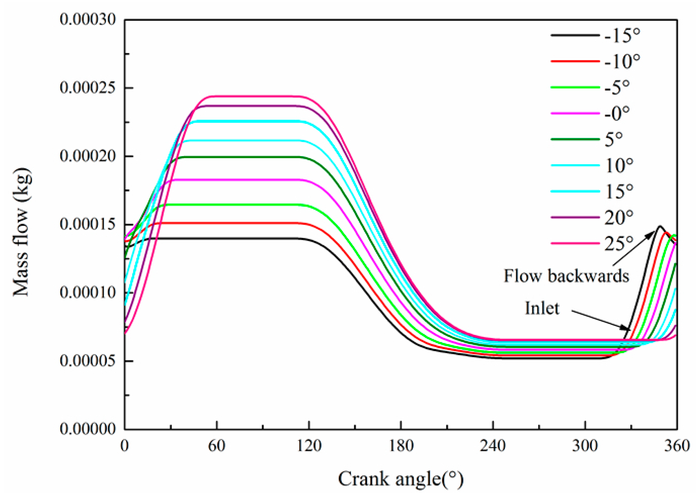
By maintaining the exhaust structure and running state of the expander, the influence of the intake angle on cylinder pressure and the instantaneous flow rate of the working fluid are determined, as shown in
Figure 11 and
Figure 12. When the intake offset angle increases negatively, the maximum pressure in the cylinder increases significantly, and the maximum pressure point occurs before TDC. When the maximum pressure is attained, the cylinder pressure is greater than the intake pipe pressure. Thus, the working fluid (steam) flows backward into the intake pipe, and the working fluid mass in the cylinder is reduced. When the intake angle has a positive offset, the intake process occurs during the piston’s down stroke. During that time, the volume of the cylinder gradually increases. Thus, the cylinder pressure and intake resistance decrease, which causes a decrease in the mass of the working fluid in the cylinder.
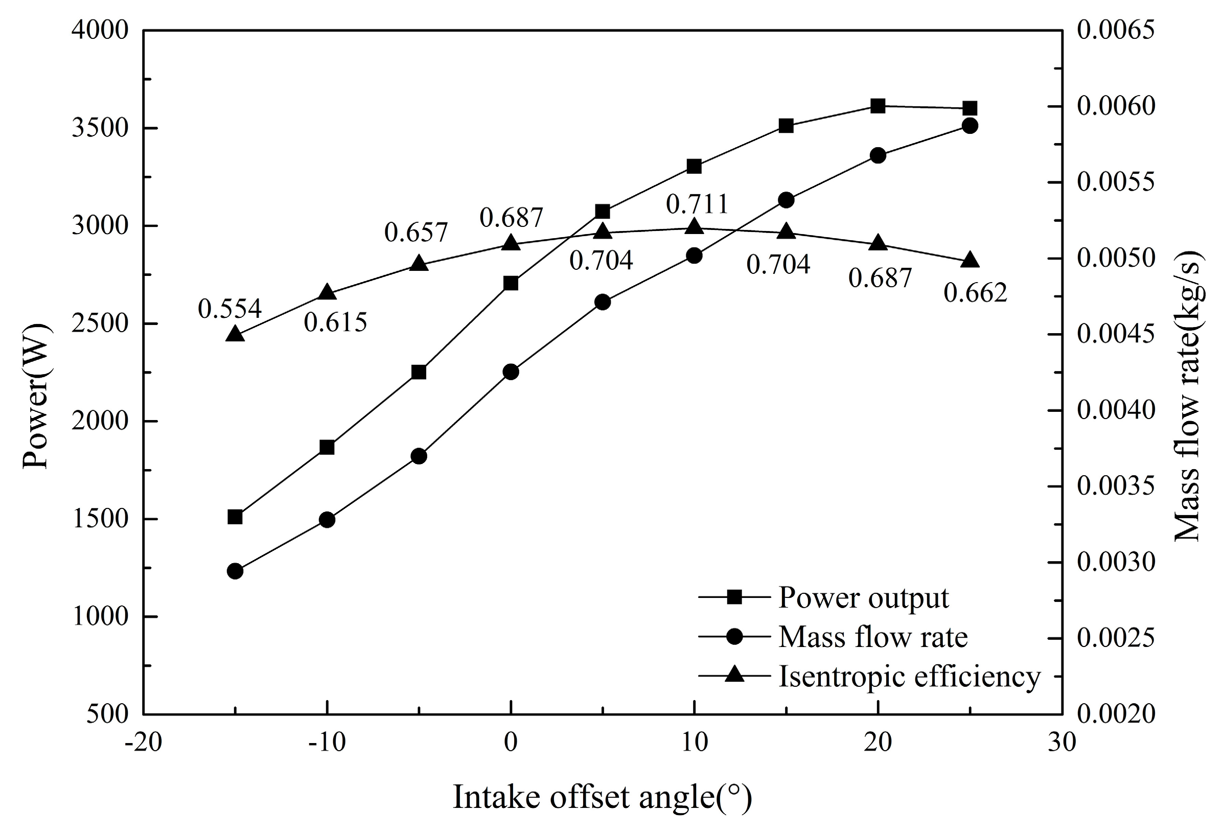
Figure 13 shows how the expander performance varies with the opening timing of the intake valve. When the intake angle offset changes from negative to positive, the rate of filling of the working fluid into the cylinder increases gradually. The output power of the expander initially increases and then decreases slightly. The output power reaches its maximum at a 20° offset angle when the intake phase is in the 340°–60° TDC region. A 1 kW increment in power can be obtained only by varying the opening timing of the intake. The isentropic efficiency of the expander initially increases and then decreases, but this variation is relatively small. The maximum efficiency occurs at a 10° offset angle.
One reason why the power output initially improves is that the intake valve opens late, but if it opens before TDC it can decrease the compression power. The other reason is that with a positive offset of the intake angle the intake process takes place mostly during the piston’s down stroke, and the cylinder volume gradually increases. This causes the cylinder pressure and intake resistance to decrease and causes the mass of the working fluid in the cylinder to increase. In addition, along with the decrease in negative work, the output power and isentropic efficiency increase.
However, if the intake opening angle is too close to TDC, the intake closing time will result in incomplete expansion of the working fluid, which will decrease the output power and isentropic efficiency of the expander. Thus, the choice of intake offset angle should consider the effects on output power and isentropic efficiency.
The expander isentropic efficiency
is defined as the ratio of the indicated work to the ideal indicated work of the expander.
In this equation, is the actual indicated power of the expander. It is determined using the indicator diagram.


