Article

Experimental Investigation on Wall Film Distribution of Dimethyl Ether/Diesel Blended Fuels Formed during Spray Wall Impingement

1
State Key Laboratory of Engines, Tianjin University, No. 92 Weijin Road, Nankai District, Tianjin 300072, China
2
School of Aerospace Mechanical and Manufacturing Engineering, The Royal Melbourne Institute of Technology University, 124 La Trobe Street, Melbourne, VIC 3000, Australia
*
Author to whom correspondence should be addressed.
Energies 2016, 9(11), 949; https://doi.org/10.3390/en9110949
Submission received: 5 October 2016 / Revised: 4 November 2016 / Accepted: 8 November 2016 / Published: 16 November 2016
(This article belongs to the Special Issue Automotive Engines Emissions and Control)

Abstract

:
Dimethyl ether (DME)/diesel blended fuels are used to improve the emissions caused by spray wall impingement during the early injection period. However, experimental results have showed that the spray wall impingement still cannot be avoided due to the engine structure and low density of the in-cylinder charge at the early injection timing. Furthermore, the wall film formed in the spray wall impingement process directly affects fuel/air mixture formation, combustion, exhaust emissions and oil quality subsequently. In this paper, the wall film distribution of DME/diesel blended fuels formed during the spray wall impingement process has been experimentally investigated. The variations of wall film distribution, wall film area and average thickness with different injection pressures, impingement distances, impingement angles and blending ratios have been discussed under both dry wall and wet wall conditions. Results showed that the wall film distribution styles were mainly determined by the spray impingement momentum. The variation of the wall film area and average thickness were affected by three factors including the impingement momentum, wall film mass and fuel properties. Correlation analysis was introduced in order to evaluate the effect of each impact factor on the variation of wall film area and average thickness.

Graphical Abstract

1. Introduction

Numbers of advanced combustion technologies have been studied in order to solve the NOx (nitrogen oxide) and soot trade-off problem of the conventional diesel engine, such as homogeneous charge compression ignition (HCCI) and premixed charge compression ignition (PCCI) combustion. Early injection strategy has been widely utilized for the HCCI and PCCI combustion in order to prolong the fuel/air mixing duration [1,2,3]. However, early injection will cause some fuel spray unavoidably impinging on the cylinder wall or piston head resulting in the formation of wall film due to the low gas density at the early injection timing [4,5].
Previous studies showed that there is a close relationship between the serious emissions and the formation of wall film on the piston head or cylinder wall. Kolodziej et al. [6] indicated that advancing the early injection timing increased the mass and number of particulate matter (PM) emission, which was attributed to the increasing amounts of fuel deposited on the piston head. Liu et al. [7] also studied the variation of the soot emission according to different early injection timing. Results also proved that the higher soot emission with earlier injection timing was caused by the wall film deposited on the cylinder wall during the spray wall impingement process. Kiplimo et al. [8] investigated the effects of spray wall impingement on the emission characteristics of a PCCI diesel engine. Results showed that the fuel impingement on the piston head led an incomplete vaporization and oxidation resulting in higher soot, hydrocarbon (HC) and carbon monoxide (CO) emissions.
The increasing trends of the emissions mentioned above caused by the formation of the wall film can be attributed into two aspects. On one hand, it develops over-rich fuel/air mixture in the impingement region [9,10]. On the other hand, pool fires also take place during the combustion process [11]. Besides, the wall film formed on the cylinder wall also have a dilution effect on the lubricating oil, which will shorten its service life [12].
Regarding the studies on the wall film distribution, high-speed photography was used by Saito et al. [13] to measure the radius of the wall film formed in the spray wall impingement process. Results showed that the wall film radius increased with increasing the injection pressure. The wall film distribution under the inclined impingement has been investigated by Mathews et al. [14], who found that the shape of the wall film became more elliptical with the increase of the impingement angle. Arai et al. [15,16] studied the effects of injection pressure, impingement distance, size of the impingement disk and impingement angle on the wall film thickness variation. The empirical relationships between the thickness and the Weber number of the impingement droplet were derived. Deng et al. [17] studied the effects of the injection duration, the impingement distance, and the impingement angle on the distribution of the gasoline wall film after spray wall interaction using laser induced fluorescence (LIF) technique. The results showed that the wall film area became larger and wall film became thicker with longer injection duration, while the opposite variation trends were observed when increasing the impingement distance. Increasing the injection angle of the disk could expand the area of the thick part of the wall film and meanwhile make the maximum film thickness smaller. Schulz et al. [18] measured the wall film distribution and mass of the iso-octane fuel using LIF methods in a constant volume vessel. Higher environmental temperature and pressure and longer impingement distance were found to increase the fuel deposits. Higher injection pressure could reduce the wall film mass only under high environmental pressure conditions.
In order to improve the emission level of the diesel engine using early injection strategy and reduce the occurrence of spray wall impingement, alternative fuels have drawn considerable research attention recently. Among several alternative fuels, dimethyl ether (DME) has been widely investigated due to its unique properties [19,20,21,22,23]. On one hand, the high oxygen content, lower stoichiometric air-fuel ratio and the absence of C–C bond of DME shows a promoting effect on reducing soot, CO and HC emissions. On the other hand, the superior evaporation characteristics of DME results shorter spray penetration length [24], smaller droplets and more uniform droplet distribution [25], which are all beneficial for limiting the phenomenon of spray wall impingement.
However, the spray–wall impingement caused by early injection still cannot be avoided when DME/diesel blended fuels are used due to the engine structure and low density of the in-cylinder charge at the early injection timing. Lee et al. [26,27] did a series of investigations into the combustion and emission characteristics of diesel engines fueled with DME or DME/diesel blended fuels using early injection strategy. Results showed that DME’s superior evaporation characteristic caused its use to decrease wall wetting and to decrease soot, HC and CO emissions compared with when using diesel. However, with the advanced injection timing strategy, the HC and CO emissions still increased which was mainly because of unavoidable spray-impingement on the cylinder walls. Park’s [28] investigation results also proved the variation of HC and CO with the injection timing mentioned above. In addition, multiple injection strategies were tried to improve the HC and CO emissions. The results pointed out that with the decrease of the 1st injection quantity, HC and CO emissions decreased obviously, however, the injection timing of the 2nd injection had little influence on the HC and CO emissions.
Because of the unavoidable spray wall impingement, considerable work has been published in recent years about the wall film characteristics. However, these are mainly focused on the pure diesel or gasoline fuels. In addition, the spray characteristics study on the DME/diesel blended fuels, if any, was always concentrating on the free penetration conditions. A better understanding of the wall film characteristics of DME/diesel blended fuels is needed. Therefore, in this paper, the wall film characteristics of DME/diesel blended fuels formed in the spray wall impingement process has been investigated. The variations of wall film distribution, wall film area and average thickness with different injection pressures, impingement distances, impingement angles and blending ratios have been discussed under both dry wall and wet wall conditions.

2. Experimental Apparatus and Procedures

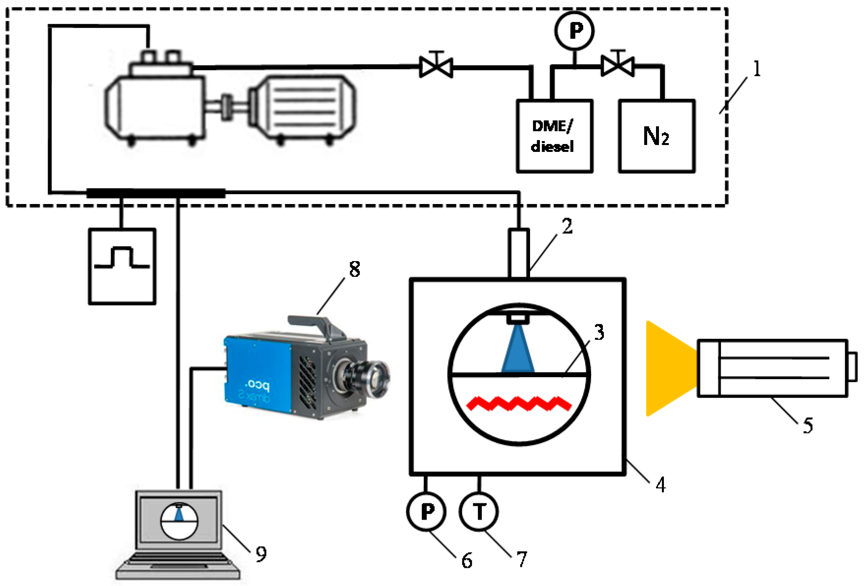
2.1. Apparatus and Materials

2.1.1. Constant-Volume Vessel

A constant-volume vessel with a common-rail injection system is linked to an image capture and data acquisition system, as shown in Figure 1 [29]. A single-hole nozzle (diameter of 0.25 mm) injector is used to inject diesel or DME/diesel blended fuels at pressure from 60 MPa to 120 MPa and the energizing duration is fixed at 1 ms. Images are obtained using an intensified charge coupled device (ICCD) camera, which has a shutter speed of 1/10,000 s and a resolution of 1024 × 1024 pixels. In addition, in order to blend the DME with the diesel fuel, the DME/diesel blended fuels should be pressurized above 0.5 MPa, considering the heating effect of the high pressure fuel pump, the pressure in the fuel tank has been fixed at 0.8 MPa.

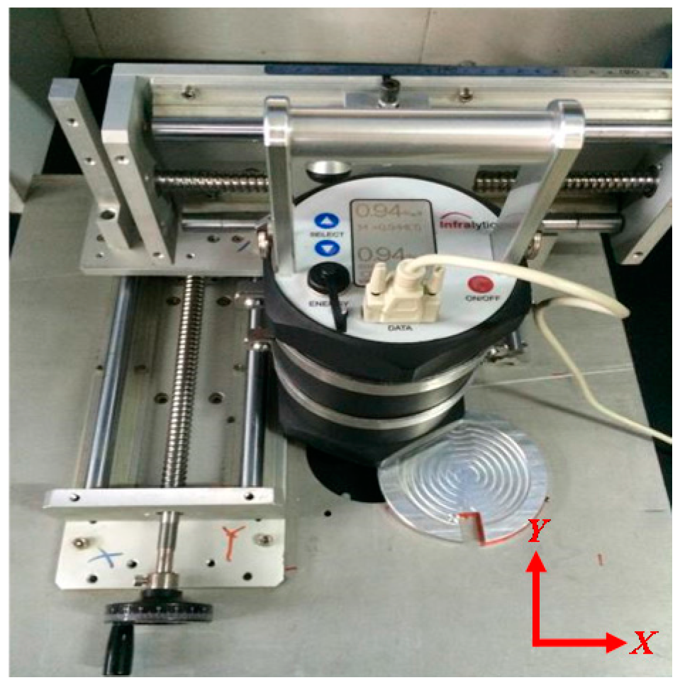
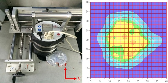
2.1.2. Wall Film Distance Measurement Device

An oil thickness sensor (Infralytic Oilsensor NG2, Infralytic GmbH, Marburg, Germany) was used to measure the thickness of film formed during the spray wall impingement process. The oil film thickness measurement is based on the law of Lambert-Beer [30]. The oil thickness sensor is installed on a supporter which can move freely in the direction of X and Y axis as shown in Figure 2. In this paper, the range of the movements of X and Y axis direction are both 0–40 mm.

2.1.3. Fuels Properties

The main physical-chemical characteristics of the 0# diesel, DME and lubricating oil that used in this study are listed in Table 1.
Variations in the physical-chemical properties of DME/diesel blended fuels at different blending ratios (mass fraction) were estimated based on the previous literature data [31] and are presented in Table 2.

2.2. Experiment Conditions

The experiment was carried out under atmospheric pressure and room temperature (298 K). On one hand, this is for the purpose to shorten the measurement time of the film thickness because the wall film thickness is changing over time, which will be discussed in the next section. On the other hand, the discharging process will cause air motion in the vessel and result the variation of the wall film distribution. These two factors lead the experiment is favor to carry out under atmospheric pressure and room temperature.
The injection pressure, impingement distance, impingement angle, and blending ratio are all varied, as summarized in Table 3. A set of conditions in which the impingement distance, injection pressure, impingement angle, and blending ratio were 60 mm, 80 MPa, 90° (vertical impingement) and 20%, respectively, is used as a reference.
The wall condition has been divided into two types: dry wall condition and wet wall condition. For dry wall condition, it simulates the condition that the spray impinges with piston head or piston bowl. And for wet wall condition, it simulates the condition that impinges with the cylinder wall covered with a layer of lubrication oil film. In addition, the thickness of the oil film covered the impingement disk is controlled at the range of 2.5–3.5 μm, which is consistent with the cylinder wall film thickness in the engine operation condition [32].

2.3. Impingement Velocity Evaluation

The concept of impingement velocity, V i m p , has been introduced to evaluate the momentum of the impinged spray. The value of V i m p can be obtained based on the spray tip movement at each impingement point, as observed by the high-speed camera operating at a rate of 10,000 frames/s as shown in Figure 3.
Because that normal impingement velocity ( V i m p ) is an approaching velocity of the droplet to the impingement wall which directly affects the droplet impact energy to the wall, so V i m p is used as impingement velocity for the inclination impingement conditions [16]. The normal impingement velocity V i m p is defined as the normal velocity as below:
V i m p = V i m p · sin θ
The values of impingement velocity V i m p and V i m p have been calculated three times under each specific set of experimental conditions, and the average values are reported in Table 4.

2.4. Experimental Procedures

2.4.1. Wall Film Mass m f i l m

The wall film mass during the spray wall impingement process was obtained by weighting the impingement disk mass difference before and after impingement. These masses are measured by an electric balance, which the accuracy is 0.1 mg. The wall film mass m f i l m is defined by Equation (2):
m f i l m = m d i s k   a f t e r   i m p i n g e m e n t m d i s k   b e f o r e   i m p i n g e m e n t
m f i l m was sampled three times in each experiment condition, and an average was presented in this paper. The data error range is less than 5%.

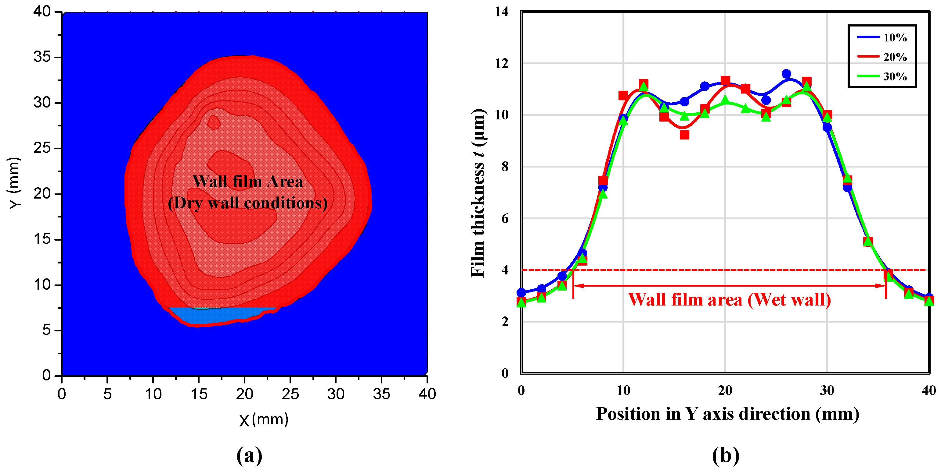
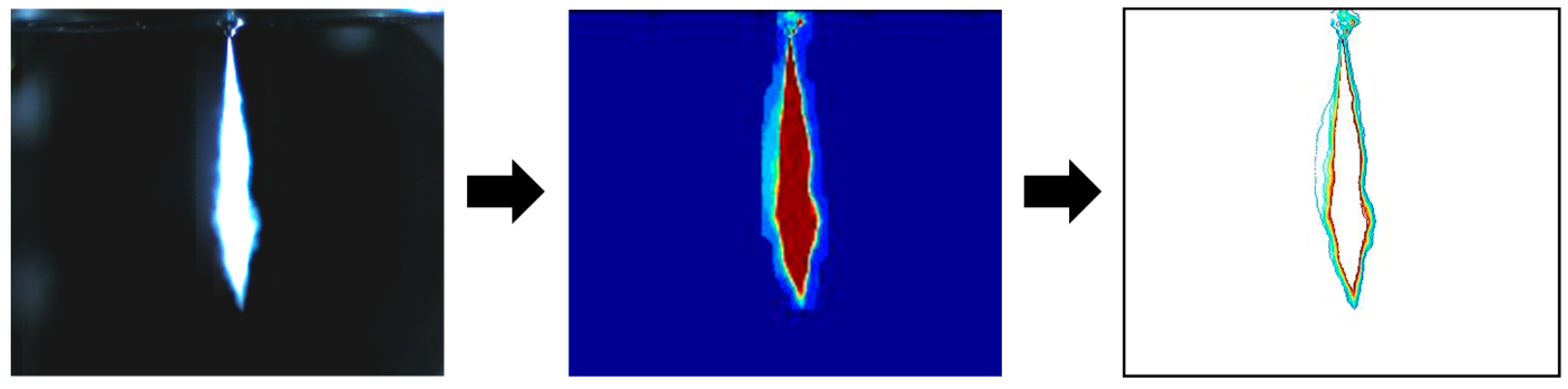
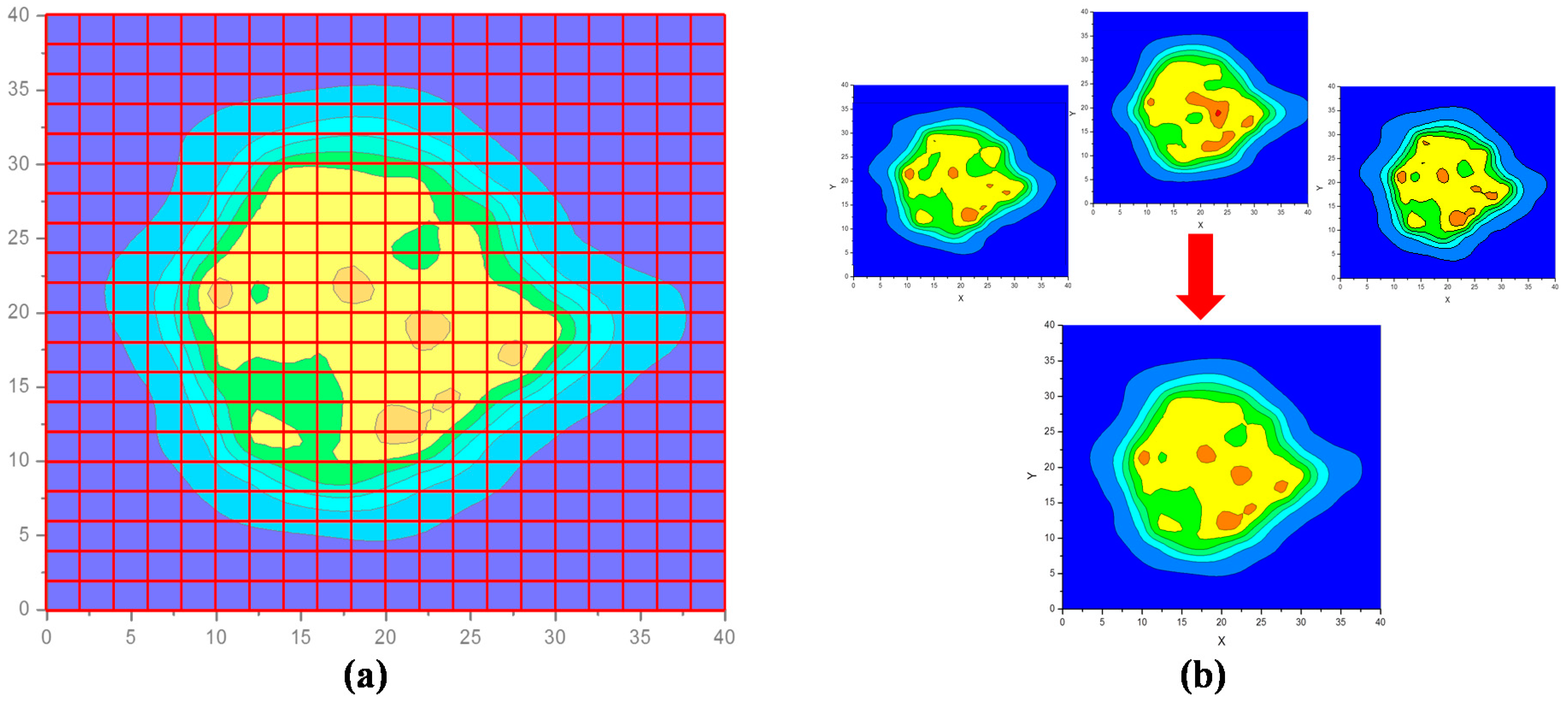
2.4.2. Wall Film Distribution

Oil thickness sensor mentioned in Section 2.1.2 was used to measure the thickness of wall film formed in the spray wall impingement duration. Firstly, the wall film distribution of the central line (X = 20 mm, Y = 0–40 mm) has been measured, and the variations of film thickness over time of dry wall conditions and wet wall conditions are obtained as shown in Figure 4 in order to determine the measurement methods. It seems that for dry wall condition, the distribution of the wall film after 25 min of start injection is almost the same as the one after 1 min. However, the film thickness varies obviously for the wet wall condition. The distribution of the wall film after 1 min and 5 min is closed, which the concavity of the wall film in the central region is small. But for the oil film distribution after 5 min, the concavity of the wall film increases obviously due to the flow diffusion between the adhered fuel and the existed lubricating oil.
Considering the film thickness variation of dry wall was not time sensitive, the wall film distribution in a square region (40 mm × 40 mm) were obtained and 441 (21 × 21) points were measured as shown in Figure 5a. The measurement duration was controlled in 20 min. The wall film distribution was sampled three times in each experimental condition and an average distribution was taken as shown in Figure 5b. The average thickness error of measured points is less than 5%. Moreover, for wet wall condition, only the wall film distribution of the central line was measured and the measurement duration was controlled in 1min. The measurement was also conducted three times for each experimental condition and an average distribution was taken and the average thickness error of measured points is less than 8%.

2.4.3. Wall Film Area

Considering the completeness of the wall film in the observation range, for dry wall conditions, the film area is defined as the area of the corresponding closed curve with 2 μm film thickness. For wet wall condition, the “film area” is defined as the horizontal distance of the points with 4 μm film thickness as illustrated in Figure 6.

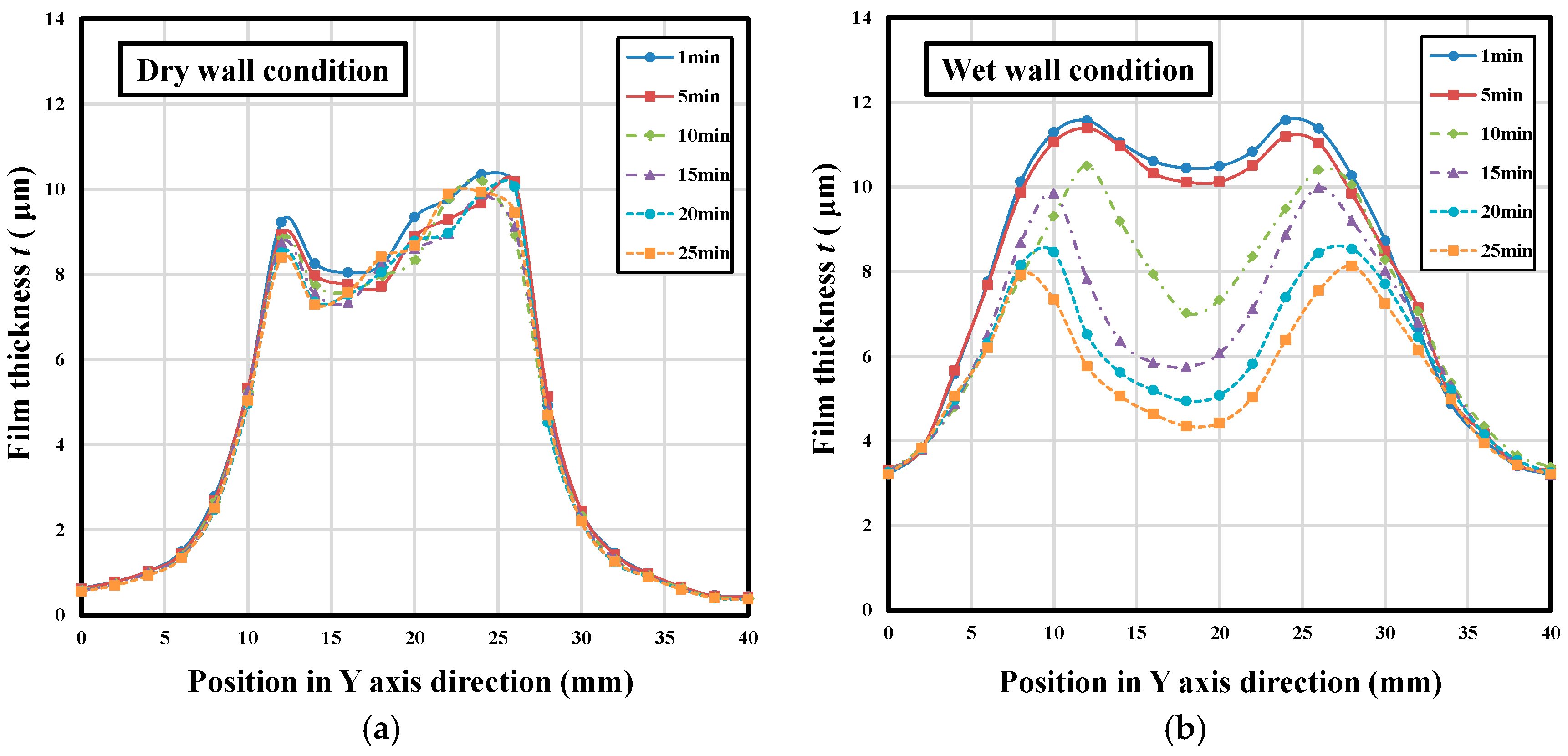
2.4.4. Wall Film Average Thickness

For dry wall condition, the wall film average thickness is defined as the average value of the thickness of the measure points which the thickness value is larger than 2 μm. For wet wall condition, wall film average thickness is calculated by averaging the integration result of the all the measure points’ thickness.

3. Results and Discussion

This paper experimentally investigated the wall film characteristics of the DME/diesel blended fuels formed in the spray wall impingement duration. The variations of wall film distribution characteristics, wall film area and average thickness with different injection pressures, impingement distances, impingement angles and blending ratios have been discussed under both dry wall and wet wall conditions.

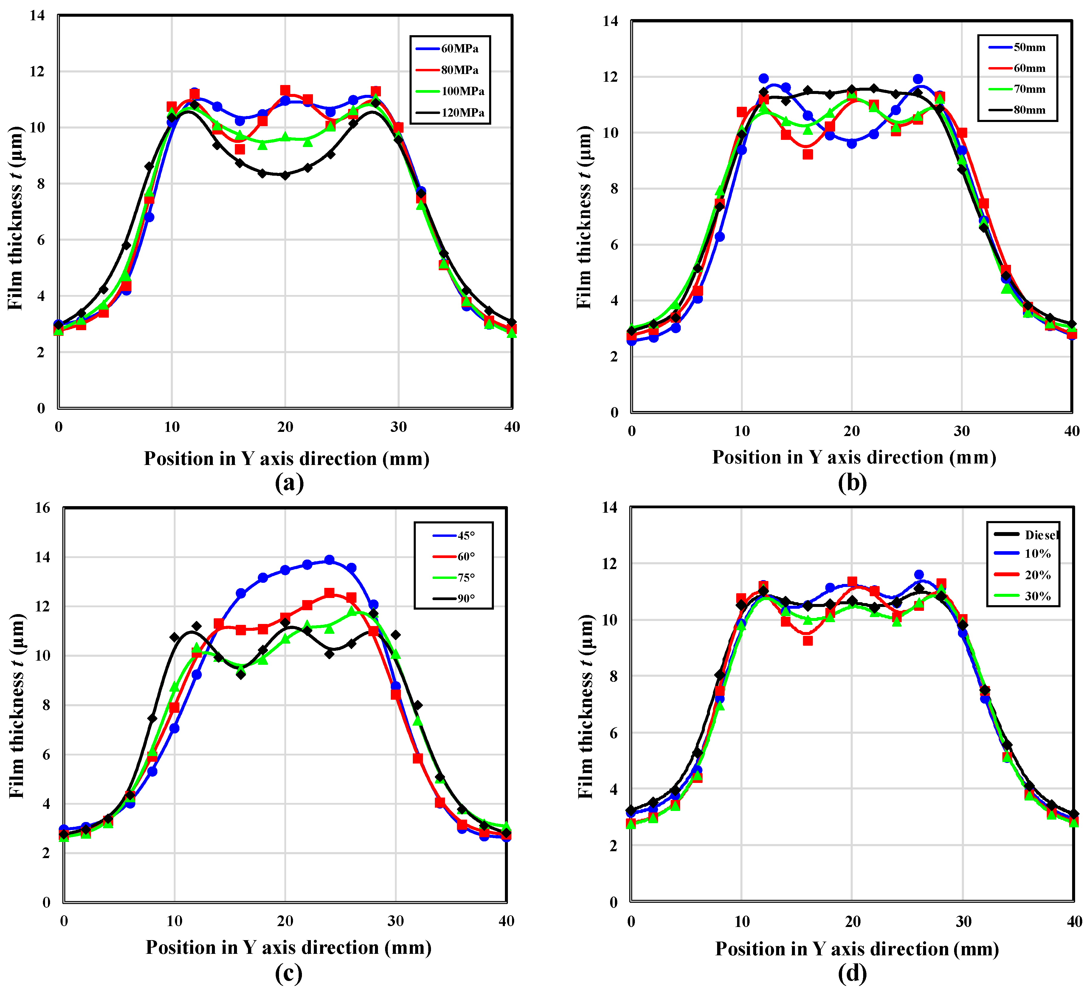
3.1. Wall Film Distribution

3.1.1. Dry Wall Conditions

The wall film distributions of different injection pressures, impingement distances, impingement angle and blending ratio under dry wall conditions are shown in Figure 7. The styles of the wall film distribution for the dry wall conditions could be divided into the “crater-shape” style and the “bulge-shape” style. For the “crater-shape” style, the wall film in the central region was thinner than the surrounding region. This was because when the impingement momentum was high enough, on one hand it would drive the deposited wall film formed in the early period spreading outwards and lead to an accumulation of fuel at the film tip due to the viscosity and retraction effects; on the other hand, it would also cause the rebound and splashing of wall film and make the wall film thinner in the central region. For the “bulge-shape” style, the wall film in the central region was thicker than the surrounding region. This was attributed to the fact that the impingement momentum was not high enough to drive the deposited fuel outwards and the rebound and splashing of the wall film in the central region also became weaker. Moreover, because of the effects of viscosity and retraction, the deposited wall film was restricted in the central region. These all caused the thick wall film in the central region and formed the “bulge-shape” style wall film distribution.
For the conditions with different injection pressures, when the injection pressure conditions was low ( P i n j = 60 MPa), it was “bulge-shape” film distribution. Further increasing the injection pressure ( P i n j = 80, 100 and 120 MPa), “crater-shape” film distribution was observed, and the contour of the wall film became irregular, and even out of the observation scope at 120 MPa condition. For all the conditions with different impingement distances, only “crater-shape” film distribution was observed. However, the area of the fuel accumulation region increased with the increase of the impingement distance. For all the conditions with different impingement angles, the film distribution represented in a “crater-shape” style except for the condition of θ = 45°. In addition, compared with the vertical impingement condition, the length of the wall film in the Y direction was much longer than the length in X direction and formed a “footprint-shape” wall film distribution style. With the increase of the impingement angle, the shape of the wall film was transformed from “footprint-shape” to “near circular shape”.
For the conditions with different blending ratios, the film distribution represented in an obvious “crater-shape” style except for the condition of diesel and 10%. The film distribution of diesel condition was a “bulge-shape” style, and the film distribution of 10% condition seemed like a transition style between “bulge-shape” and “crater-shape”. This result was in conflict with the variation that higher impingement momentum resulted the “crater-shape” style wall film. It was because that the variations of impingement momentum with different blending ratio was limited, however, the viscosity and retraction effects became weaker obviously with the increase of the blending ratio due to the lower viscosity and surface tension of the blended fuels.

3.1.2. Wet Wall Conditions
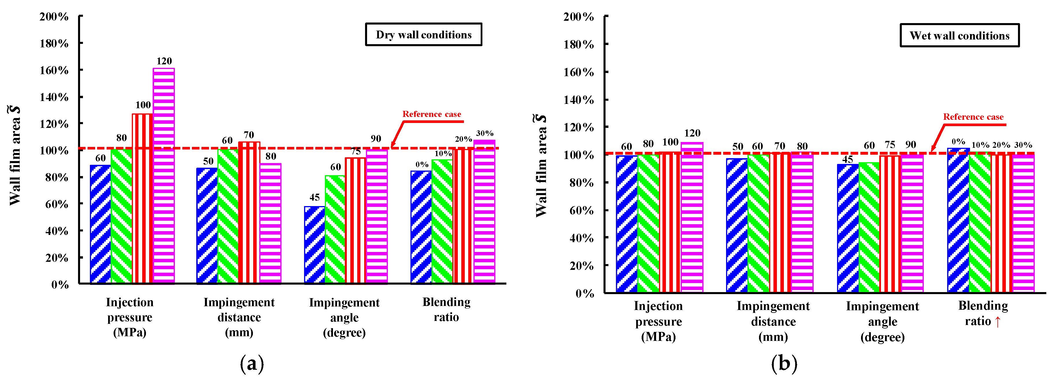
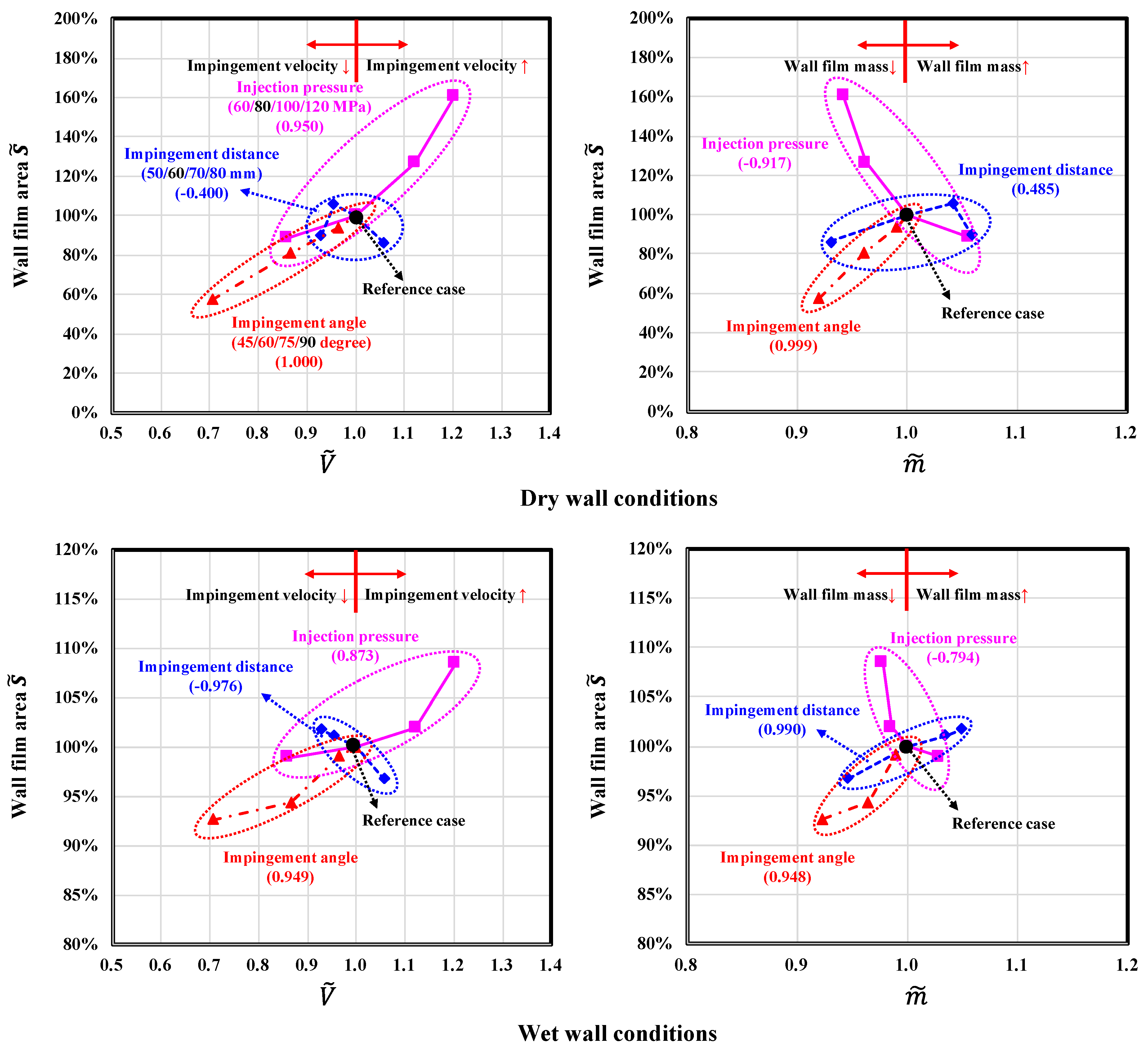
The wall film distributions of different injection pressures, impingement distances, impingement angle and blending ratio under wet wall conditions are shown in Figure 8.
Based on the two wall film distribution styles of the dry wall conditions mentioned above, there was a new style added for the wet wall conditions which was called “W-shape” in this paper. The reasons of the formation of “crater-shape” and “bulge-shape” wall film distribution were similar to the dry wall condition. The “W-shape” wall film distribution seemed like a combination style between the “bulge-shape” and “crater-shape” which represented a moat-like distribution. This special distribution was mainly attributed to the higher viscosity and surface tension of the existed oil film, which enhanced the viscosity and retraction effects of the wall film.
With the increase of the injection pressure, the wall film distribution was flat in the central region at first, then changed into the “W-shape” distribution and changed into “crater-shape” distribution at last. In addition, the concavity of the wall film increased due to the higher impingement momentum as shown in Figure 8a. The opposite variation trend was observed with the increase of the impingement distance. The “crater-shape” distribution was first observed, then the “W-shape” distribution and finally the “bulge-shape” distribution due to the continued decline of the impingement momentum as shown in Figure 8b.
Different from the vertical impingement, the wall film distribution for the inclination impingement was unsymmetrical as shown in Figure 8c. The film in the upstream region (positive Y direction) was thicker than the film in the downstream region (negative Y direction) due to the fuel accumulation in the upstream region. With the increase of the impingement angle, the wall film changed from “bulge-shape” distribution into “W-shape” distribution due to the increase of the impingement momentum. Moreover, the wall film in the downstream region became thicker and film in the upstream region became thinner, and finally obtained the symmetry wall film distribution.
The wall film distributions for conditions with different blending ratios are shown in Figure 8d. For the diesel conditions, it seemed like a “crater-shape” distribution, then changed into a “W-shape” distribution, and the “W-shape” distribution was more obvious for the 20% condition, however, the “W-shape” became unobvious again with the increase of the blending ratio. This was because the trade-off effects of the impingement momentum and the viscosity and retraction effects.

3.2. Wall Film Area

In order to clearly compare the contribution of each experimental variable to wall film area variation, a dimensionless number about the wall film area S ˜ is introduced and is defined as below:
S ˜ = S i / S 0
where the subscript i represents each experiment condition and the subscript 0 represents the reference case. If the value of S ˜ is greater than 100%, it means the wall film area is larger than the reference case, while represents smaller. The variations of wall film area according to each experiment variable under both dry wall and wet wall conditions are provided in Figure 9.
Increasing the injection pressure and impingement angle all increased the wall film area for either dry wall or wet wall conditions. However, with the increase of the impingement distance, the variation trend of the wall film area showed an increasing trend followed by a decreasing trend for the dry wall conditions, while a continuous increase trend for the wet wall conditions. When the blending ratio increased, an opposite variation trends for dry wall and wet wall conditions was obtained, an increasing trend for the dry wall conditions, while, a decreasing trend for the wet wall conditions. In addition, the variation level of the wet wall conditions was much lower than the dry wall conditions.
In the process of wall film formation, the wall film area can be directly affected by three main factors. The first one is the wall film mass, and increasing the wall film mass has a positive effect on increasing the wall film area. The second one is the impingement momentum, higher impingement momentum prompts the wall film spreading resulting in a larger wall film area. The last one is the spreading resistance, which is divided into liquid-solid and liquid-liquid resistance for the dry wall and wet wall condition respectively. The spreading resistance is determined by the fuel properties especially the viscosity and surface tension, and lower fuel viscosity and surface tension had a positive effect on wall film spreading and increased the wall film area. However, the higher viscosity and surface tension of the lubricating oil film for the wet wall conditions greatly increased the spreading resistance and weakened the effect of fuel property variation.
The wall film area variation caused by variables including injection pressure, impingement distance and impingement angle can be attribute to the effects of impingement momentum and wall film mass because the properties of the blended fuels are unchanged. In order to evaluate the contribution of these two impact factors on the wall film area variation, the correlation analysis has been carried on and dimensionless number of the impingement velocity V ˜ and wall film mass m ˜ are introduced to evaluate the magnitude of impingement momentum and wall film mass respectively, which are defined as below:
V ˜ = V i / V 0 , m ˜ = m i / m 0
where the subscript i represents each experiment condition and the subscript 0 represents the reference case. The correlation coefficients between wall film area and dimensionless number V ˜ and m ˜ for both dry wall and wet wall conditions have been obtained as shown in Figure 10. When the correlation coefficient is closed to 1 or −1, it represents better positive or negative correlation. However, when the correlation coefficient is closed to 0, it represents no correlation between the two variables.
With the increase of the injection pressure, the impingement momentum increased which promoted wall film spreading and was beneficial for increasing the wall film area. However, the wall film mass reduced which had a negative effect on increasing the wall film area. The increasing trend of the wall film area indicated that the effect of the less wall film mass on reducing the wall film area was masked by the effect of higher impingement momentum on increasing the wall film area. Besides, the effect of impingement momentum was stronger and the effect of wall film mass was weaker for the dry wall conditions comparing with the wet wall conditions.
For the conditions with different impingement distances, with the increase of the impingement distance, the impingement momentum decreased which was against with the increase of the wall film area, while the wall film mass increased which was beneficial for the wall film area increasing. Based on the correlation analysis results, the wall film area was mainly controlled by the impact factor of wall film mass especially under the wet wall conditions which the effect of the impingement momentum was completely masked by the effect of wall film mass whatever the impingement distance was. Under the dry wall conditions, the effect of impingement momentum strengthened gradually, while the effect of wall film mass became weaker with the increase of the impingement distance.
When increasing the impingement angles, both the impingement momentum and the wall film mass increased, which were all beneficial for increasing the wall film area. The impact factors of impingement momentum and wall film mass approximately had the same influences on wall film area. And these two impact factors were stronger for the dry wall conditions than wet wall conditions.
The increasing trend of the wall film area with the increase of the blending ratio under the dry wall conditions could be explained by the decrease of viscosity and surface tension of the blended fuels which reduced the spreading resistance and assisted the film spreading. However, the decreasing wall film mass due to the higher saturated vapor pressure and the decreasing impingement momentum both played negative roles in increasing the wall film area resulting in a slower the increasing rate. The opposite variation trend under the wet wall conditions was mainly attributed to the decrease of wall film mass and the impingement momentum. The effect of the lower viscosity and surface tension on prompting the film spreading was very limited due to the exist of the lubricating oil film.

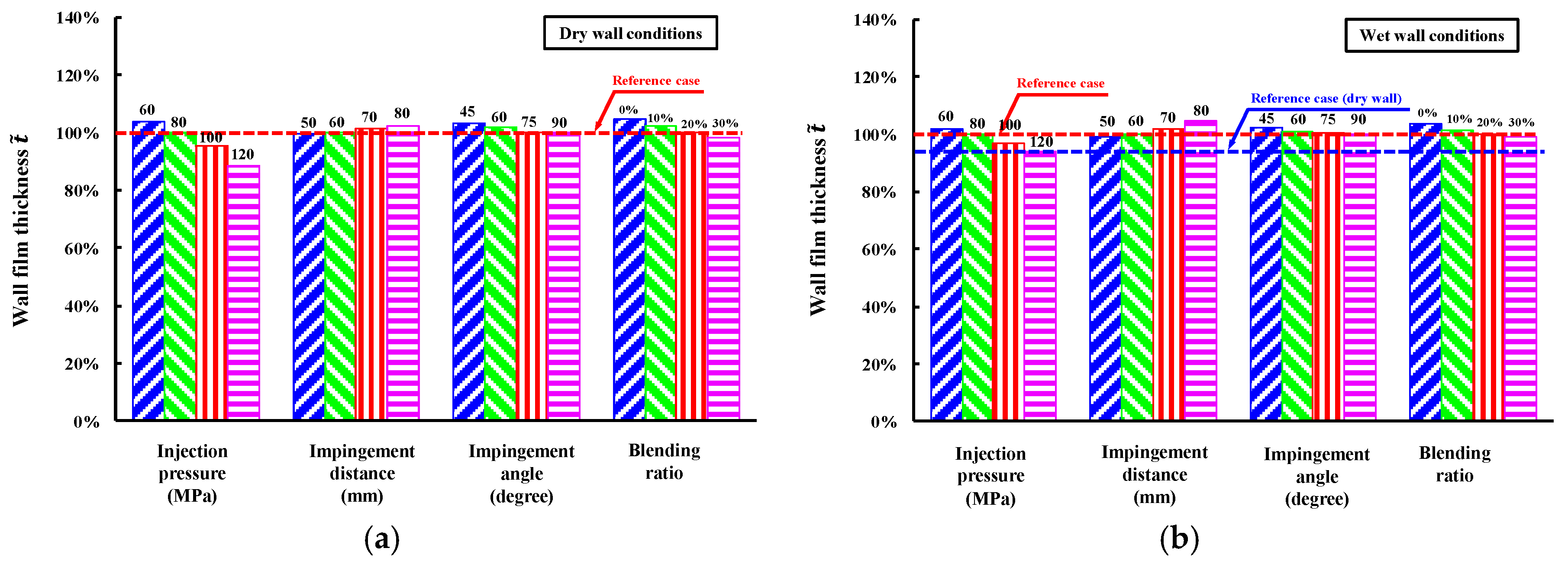
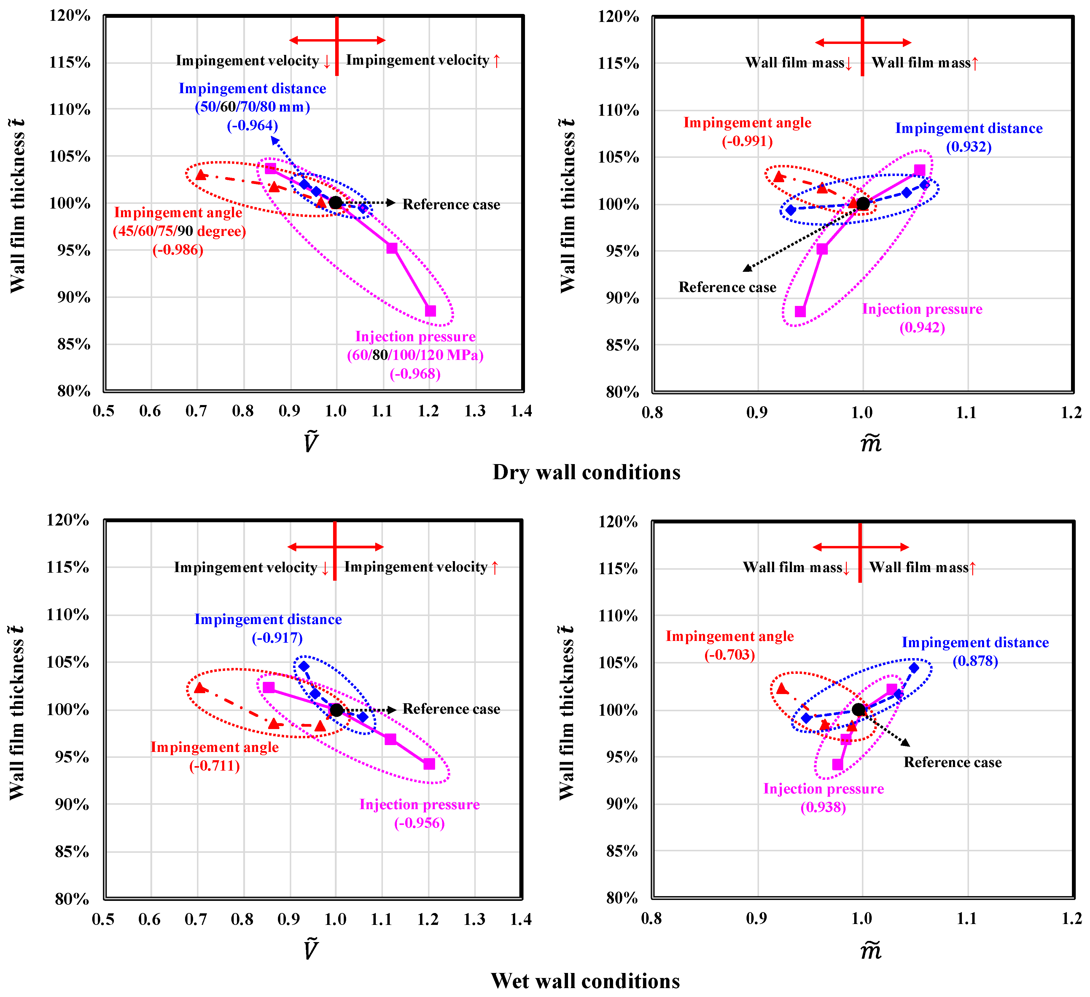
3.3. Wall Film Average Thickness

In order to clearly compare the contribution of each experimental variable to wall film average thickness variation, a dimensionless number about the wall film average thickness t ˜ is introduced and is defined as below:
t ˜ = t i / t 0
The variation of wall film average thickness according to each experimental variable under both dry wall and wet wall conditions is provided in Figure 11.
The variation of the wall film average thickness showed a consistent trend between the dry wall and wet wall conditions. Increasing the injection pressure, impingement angle and blending ratio all decreased the wall film average thickness except for the impingement distance. In addition, for wet wall conditions, the wall film average thickness always larger than the dry wall conditions, however the variation level was lower.
Like the wall film area variation discussed in the Section 3.2, there were also three factors influenced the wall film average thickness including the impingement momentum, wall film mass and the properties of the blended fuels. Higher impingement momentum, lower viscosity and lower surface tension all prompted the film spreading and resulted a thinner wall film. However, the high wall film mass led to an increase of wall film average thickness.
The wall film average thickness variation caused by variables including injection pressure, impingement distance and impingement angle could be attribute to the effects of impingement momentum and wall film mass. The correlation coefficients between wall film average thickness and dimensionless number V ˜ and m ˜ were obtained as shown in Figure 12 for both dry wall and wet wall conditions.
Increasing the injection pressure increased the impingement momentum while decreased the wall film mass, which both had the effect on reducing the wall film average thickness under dry wall and wet wall conditions. The impact factors of impingement momentum and wall film mass approximately had the same influences on wall film average thickness, moreover, these two factors had slight stronger effects for the dry wall conditions than the wet wall conditions.
On the contrary to the conditions varying the injection pressure, with the increase of the impingement distance, the impingement momentum decreased while the wall film mass increased, which both had the effect on increasing the wall film average thickness. Moreover, the effect of impingement momentum was slight stronger than the wall film mass, and both of these two impact factors were stronger for the dry wall conditions than the wet wall conditions.
When increasing the impingement angles, the impingement momentum increased which was beneficial for reducing the wall film average thickness, while the wall film mass increased which led an increase of thickness value. The decreasing trend of the wall film average thickness with the increase of the impingement angle indicated that impingement momentum was the major impact factor on the wall film average thickness variation for the conditions varying the impingement angle. And the effect of wall film mass was masked by the impingement momentum, which could be proved by the inconsistent variation trend of the average thickness with the increase of the wall film mass. Besides, the effect of the impingement momentum and the wall film mass became weaker and stronger respectively for the wet wall conditions.
The decrease of the wall film average thickness with higher blending ratio was attributed to the lower wall film mass due to the higher saturated vapor pressure. Besides, the decrease of the viscosity and surface tension of the blended fuels also contributed the reduction of wall film average thickness especially for the dry wall conditions.

4. Conclusions

Experiments were carried out to study the wall film characteristics of the DME/diesel blended fuels which formed in the spray wall impingement duration. The variations of wall film distribution, wall film area and average thickness with different injection pressures, impingement distances, impingement angles and blending ratios were discussed under both dry wall and wet wall conditions. Conclusions can be drawn from this work:
(1)
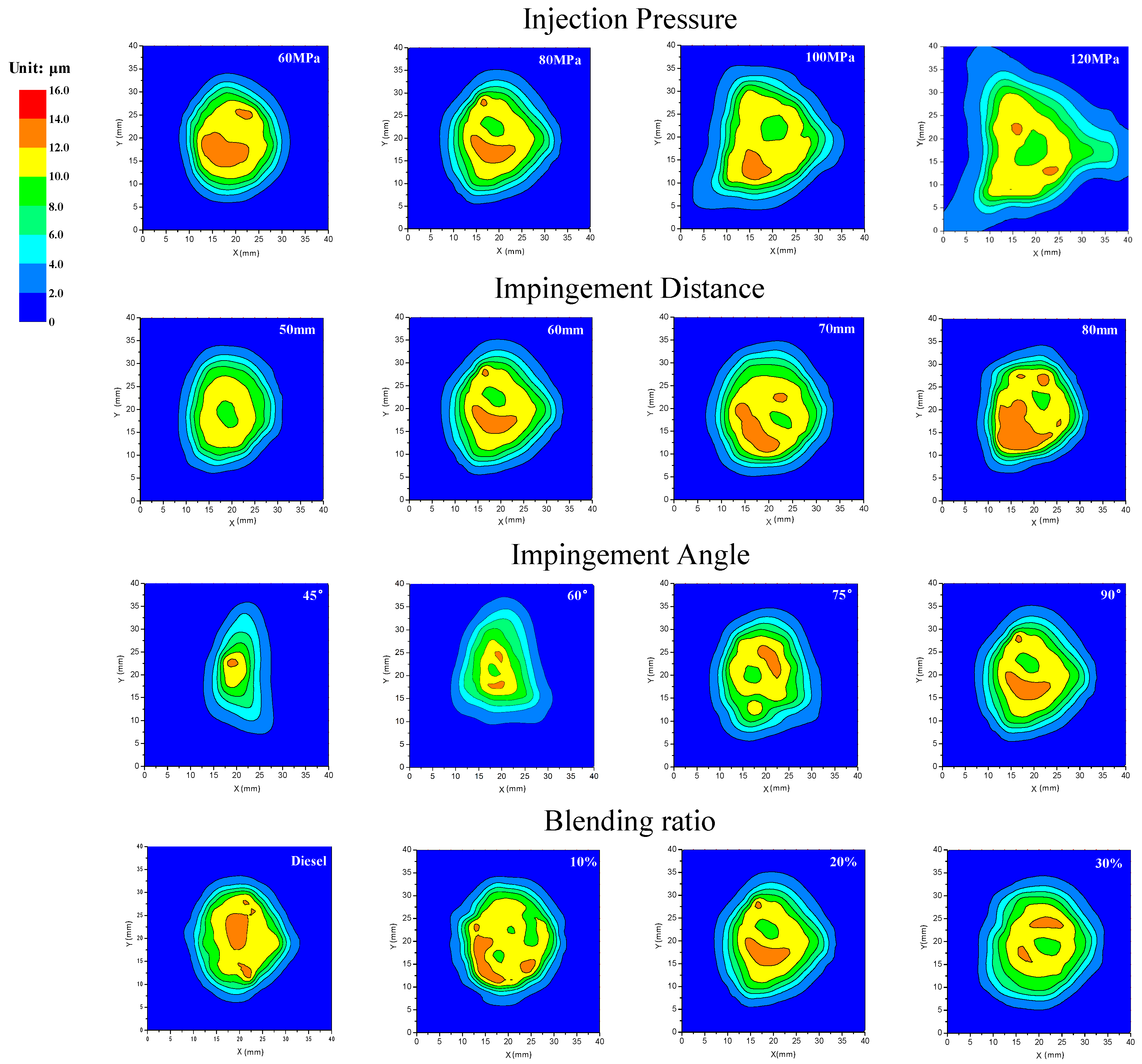
The wall film distribution is mainly affected by the impingement momentum. For dry wall conditions, there are two distribution styles: “crater-shape” and “bulge-shape”. For wet wall conditions, except for the two styles above, there added a new style called “W-shape”, which is a combination of or transition style between the “bulge-shape” and “crater-shape”.
(2)
With the increase of the injection pressure, wall film area increases while the average thickness decreases for either dry wall or wet wall conditions. Increasing the impingement distance, wall film area first increases then decreases for dry wall conditions while continuously increases for wet wall conditions. The wall film average thickness increases whatever the wall condition is.
(3)
With the increase of the impingement angle, for both dry wall and wet wall conditions, continuously increasing and decreasing trends for the wall film area and average thickness are obtained for both dry wall and wet wall conditions. Increasing the blending ratio of the blended fuels, the wall film average thickness decreases whatever the wall condition is, and wall film area increases for dry wall conditions and decreases for wet wall conditions.
(4)
The variation of the wall film area and average thickness are affected by three factors including the impingement momentum, wall film mass and fuel properties. Higher impingement momentum promotes the wall film spreading and a larger and thinner wall film can be obtained. More wall film mass increases the wall film area and average thickness. Lower viscosity and surface tension are also beneficial for increasing the wall film area while decreasing the average thickness. Higher saturated vapor pressure reduces the wall film mass which is also beneficial for decreasing the wall film area and average thickness.
(5)
The variation level caused by variables including injection pressure, impingement distance, impingement angle and the blending ratio in wall film area and average thickness under the wet wall conditions is lower than the dry wall conditions due to the higher viscosity and surface tension of the existed lubricating oil film.

Acknowledgments

This work was supported by National Natural Science Foundation of China (Nos. 51376136 and 51406132) and Natural Science Foundation of Tianjin (No. 14JCYBJC21300).

Author Contributions

Hanzhengnan Yu designed the experimental apparatus, discussed the results and implications, and commented on the manuscript at all stages. Hanzhengnan Yu and Hongsheng Zhang performed the spray experiments. The research direction was provided by Xingyu Liang and Gequn Shu. Xu Wang and Yuesen Wang helped to check the English.

Conflicts of Interest

The authors declare no conflict of interest.

References

  1. Yao, M.; Zheng, Z.; Liu, H. Progress and recent trends in homogeneous charge compression ignition (HCCI) engines. Prog. Energy Combust. Sci. 2009, 35, 398–437. [Google Scholar] [CrossRef]
  2. Berggren, C.; Magnusson, T. Reducing automotive emissions—The potentials of combustion engine technologies and the power of policy. Energy Policy 2012, 41, 636–643. [Google Scholar] [CrossRef]
  3. Musculus, M.P.B.; Miles, P.C.; Pickett, L.M. Conceptual models for partially premixed low-temperature diesel combustion. Prog. Energy Combust. Sci. 2013, 39, 246–283. [Google Scholar] [CrossRef]
  4. Kook, S.; Park, S.; Bae, C. Influence of early fuel injection timings on premixing and combustion in a diesel engine. Energy Fuels 2007, 22, 331–337. [Google Scholar] [CrossRef]
  5. Kitasei, T.; Yamada, J.; Shoji, T.; Shiino, S.; Mori, K. Influence of the Different Fuel Spray Wall Impingement Angles on Smoke Emission in a DI-Diesel Engine; SAE Technical Paper 2008-01-1791; SAE International: Warrendale, PA, USA, 2008. [Google Scholar]
  6. Benajes, J.; García-Oliver, J.M.; Novella, R.; Kolodziej, C. Increased particle emissions from early fuel injection timing Diesel low temperature combustion. Fuel 2012, 94, 184–190. [Google Scholar] [CrossRef]
  7. Liu, H.; Zhong, Z.; Zheng, Z.; Zheng, Z.; Yao, M. Study of the control strategies on soot reduction under early-injection conditions on a diesel engine. Fuel 2015, 139, 472–481. [Google Scholar] [CrossRef]
  8. Kiplimo, R.; Tomita, E.; Kawahara, N.; Yokobe, S. Effects of spray impingement, injection parameters, and EGR on the combustion and emission characteristics of a PCCI diesel engine. Appl. Ther. Eng. 2012, 37, 165–175. [Google Scholar] [CrossRef]
  9. Peng, Z.; Liu, B.; Wang, W.; Lu, L. CFD investigation into diesel PCCI combustion with optimized fuel injection. Energies 2011, 4, 517–531. [Google Scholar] [CrossRef]
  10. Yu, H.; Guo, Y.; Li, D.; Liang, X.; Shu, G.; Wang, Y.; Wang, X.; Dong, L. Numerical Investigation of the Effect of Spray Cone Angle on Mixture Formation and CO/Soot Emissions in an Early Injection HCCI Diesel Engine; SAE Technical Paper 2015-01-1070; SAE International: Warrendale, PA, USA, 2015. [Google Scholar]
  11. Fang, T.; Lee, C.F.F. Low sooting combustion of narrow-angle wall-guided sprays in an HSDI diesel engine with retarded injection timings. Fuel 2011, 90, 1449–1456. [Google Scholar] [CrossRef]
  12. Jia, M.; Peng, Z.; Xie, M.; Stobart, R. Evaluation of Spray/Wall Interaction Models under the Conditions Related to Diesel HCCI Engines; SAE Technical Paper 2008-01-1632; SAE International: Warrendale, PA, USA, 2008. [Google Scholar]
  13. Saito, A.; Kawamura, K.; Watanabe, S.; Takahashi, T.; Tuzuki, N. Analysis of impinging spray characteristics under high-pressure fuel injection (1st report, measurements of impinging spray characteristics). Trans. Jpn. Soc. Mech. Eng. Part B 1993, 59, 3290–3295. [Google Scholar] [CrossRef]
  14. Mathews, W.S.; Lee, C.F.; Peters, J.E. Experimental investigations of spray/wall impingement. At. Sprays 2003, 13, 223–242. [Google Scholar] [CrossRef]
  15. Akop, M.Z.; Zama, Y.; Furuhata, T.; Arai, M. Characteristics of adhesion of diesel fuel on impingement disk wall. Part 1: Effect of Impingement area and inclination angle of disk. At. Sprays 2013, 23, 725–744. [Google Scholar] [CrossRef]
  16. Akop, M.Z.; Zama, Y.; Furuhata, T.; Arai, M. Characteristics of adhesion of diesel fuel on impingement disk wall. Part 2: Droplet Weber number and adhered fuel mass. At. Sprays 2014, 24, 651–671. [Google Scholar] [CrossRef]
  17. Cheng, Y.S.; Deng, K.; Li, T. Measurement and simulation of wall-wetted fuel film thickness. Int. J. Ther. Sci. 2010, 49, 733–739. [Google Scholar] [CrossRef]
  18. Schulz, F.; Samenfink, W.; Schmidt, J.; Beyrau, F. Systematic LIF fuel wall film investigation. Fuel 2016, 172, 284–292. [Google Scholar] [CrossRef]
  19. Yoon, S.K.; Kim, M.S.; Kim, H.J.; Choi, N.J. Effects of canola oil biodiesel fuel blends on combustion, performance, and emissions reduction in a common rail diesel engine. Energies 2014, 7, 8132–8149. [Google Scholar] [CrossRef]
  20. Ge, J.C.; Kim, M.S.; Yoon, S.K.; Choi, N.J. Effects of pilot injection timing and EGR on combustion, performance and exhaust emissions in a common rail diesel engine fueled with a canola oil biodiesel-diesel blend. Energies 2015, 8, 7312–7325. [Google Scholar] [CrossRef]
  21. Park, S.H.; Lee, C.S. Applicability of dimethyl ether (DME) in a compression ignition engine as an alternative fuel. Energy Convers. Manag. 2014, 86, 848–863. [Google Scholar] [CrossRef]
  22. Sakuragi, K.; Li, P.; Otaka, M.; Makino, H. Recovery of Bio-Oil from Industrial Food Waste by Liquefied Dimethyl Ether for Biodiesel Production. Energies 2016, 9. [Google Scholar] [CrossRef]
  23. Arcoumanis, C.; Bae, C.; Crookes, R.; Kinoshita, E. The potential of di-methyl ether (DME) as an alternative fuel for compression-ignition engines: A review. Fuel 2008, 87, 1014–1030. [Google Scholar] [CrossRef]
  24. Lee, S.; Jeong, S.; Lim, O. An investigation on the spray characteristics of DME with variation of ambient pressure using the common rail fuel injection system. J. Mech. Sci. Technol. 2012, 26, 3323–3330. [Google Scholar] [CrossRef]
  25. Li, G.; Cao, J.; Li, M.; Quan, Y.; Chen, Z. Experimental study on the size distribution characteristics of spray droplets of DME/diesel blended fuels. Fuel Process. Technol. 2012, 104, 352–355. [Google Scholar] [CrossRef]
  26. Park, S.H.; Kim, H.J.; Lee, C.S. Effects of dimethyl-ether (DME) spray behavior in the cylinder on the combustion and exhaust emissions characteristics of a high speed diesel engine. Fuel Process. Technol. 2010, 91, 504–513. [Google Scholar] [CrossRef]
  27. Yoon, S.H.; Han, S.C.; Lee, C.S. Effects of high EGR rate on dimethyl ether (DME) combustion and pollutant emission characteristics in a direct injection diesel engine. Energies 2013, 6, 5157–5167. [Google Scholar] [CrossRef]
  28. Park, S.H.; Yoon, S.H. Injection strategy for simultaneous reduction of NOx and soot emissions using two-stage injection in DME fueled engine. Appl. Energy 2015, 143, 262–270. [Google Scholar] [CrossRef]
  29. Yu, H.; Liang, X.; Shu, G.; Wang, Y.; Zhang, H. Experimental investigation on spray-wall impingement characteristics of n-butanol/diesel blended fuels. Fuel 2016, 182, 248–258. [Google Scholar] [CrossRef]
  30. Infralytic GmbH. Oil-Thickness Sensor NG Operating Manual; Version 1.6.3; Infralytic GmbH: Marburg, Germany, 2011. [Google Scholar]
  31. Tong, J. Thermal Physical Properties of the Fluid: Basic Principle and Calculation; China Petrochemical Press: Beijing, China, 2008. [Google Scholar]
  32. Ye, X. Numerical Investigation and Application of Three-Dimensional Lubrication Performance in Piston Ring Pack. Ph.D. Thesis, Huazhong University of Science and Technology, Wuhan, China, 2004. [Google Scholar]
Figure 1. Visualization system for spray wall impingement (1—common-rail system; 2—nozzle; 3—impingement disk; 4—volume constant vessel; 5—light source; 6—pressure sensor; 7—temperature sensor; 8—intensified charge coupled device (ICCD) camera; 9—data acquisition system). DME: dimethyl ether.
Energies 09 00949 g001
Figure 2. Wall film thickness measurement device.
Energies 09 00949 g002
Figure 3. Experimental extraction of impingement velocity.
Energies 09 00949 g003
Figure 4. Variations of film thickness over time of: (a) dry wall conditions; and (b) wet wall conditions.
Energies 09 00949 g004
Figure 5. Wall film distribution obtained methods for dry wall conditions: (a) the distribution of the measurement points (21 × 21); (b) the average distribution of the wall film taken methods.
Energies 09 00949 g005
Figure 6. Definition of the wall film area for: (a) dry wall conditions; and (b) wet wall conditions.
Energies 09 00949 g006
Figure 7. Wall film distributions under dry wall conditions.
Energies 09 00949 g007
Figure 8. Wall film distributions of different: (a) injection pressures; (b) impingement distances; (c) impingement angles; and (d) blending ratios under wet wall conditions.
Energies 09 00949 g008
Figure 9. Variations of wall film area under different experiment conditions for: (a) dry wall conditions; and (b) wet wall conditions.
Energies 09 00949 g009
Figure 10. Relationships between wall film area and dimensionless number V ˜ and m ˜ .
Energies 09 00949 g010
Figure 11. Variations of wall film average thickness under different experiment conditions for: (a) dry wall conditions; and (b) wet wall conditions.
Energies 09 00949 g011
Figure 12. Relationships between wall film average thickness and dimensionless number V ˜ and m ˜ .
Energies 09 00949 g012
Table 1. Physical-chemical characteristics of 0# diesel, DME and lubricating oil.
Physical-Chemical Characteristics0# DieselDMELubricating Oil
Density (kg/m3, 298 K)848665856
Kinematic viscosity (mPa·s, 298 K)3.80.16164.6
Surface tension (mN/m, 298 K)35.412.0-
Saturated Vapour pressure (kPa, 298 K)1.9518.5-
Table 2. Physical-chemical characteristics of and DME/diesel blended fuel with different blending ratio.
Physical-Chemical CharacteristicsBlending Ratio
10%20%30%
Density (kg/m3, 298 K)826804784
Kinematic viscosity (mPa·s, 298 K)1.60.90.6
Surface tension (mN/m, 298 K)32.229.226.4
Saturated Vapour pressure (kPa, 298 K)138.6233.0302.2
Table 3. Experimental conditions.
Varying Injection Pressure
Impingement distance: 60 mm, Impingement angle: 90°, Blending ratio: 20%
Injection pressure (MPa)6080100120
Varying Impingement Distance
Injection pressure: 80 MPa, Impingement angle: 90°, Blending ratio: 20%
Impingement distance (mm)50607080
Varying Impingement Angle
Impingement distance: 60 mm, Injection pressure: 80 MPa, Blending ratio: 20%
Impingement angle (°)45607590
Varying Blending Ratio
Injection pressure: 80 MPa, Impingement distance: 60 mm, Impingement angle: 90°
Blending ratio (Mass fraction)Diesel10%20%30%
Table 4. Impingement velocity of different experimental conditions.
Injection pressure (MPa)6080100120
V i m p (m/s)181.7211.5237.2254.6
Impingement distance (mm)50607080
V i m p (m/s)223.6211.5202.2196.7
Impingement angle (°)45607590
V i m p (m/s)149.5183.2204.3211.5
Blending ratio (Mass fraction)Diesel10%20%30%
V i m p (m/s)212.7212.2211.5210.7

