Article

Nonlinear Coupled Dynamics of a Rod Fastening Rotor under Rub-Impact and Initial Permanent Deflection

School of Energy, Power and Mechanical Engineering, North China Electric Power University, Beijing 102206, China
*
Authors to whom correspondence should be addressed.
Energies 2016, 9(11), 883; https://doi.org/10.3390/en9110883
Submission received: 22 August 2016 / Revised: 18 October 2016 / Accepted: 24 October 2016 / Published: 28 October 2016
(This article belongs to the Special Issue Electric Power Systems Research 2017)

Abstract

:
A nonlinear coupled dynamic model of a rod fastening rotor under rub-impact and initial permanent deflection was developed in this paper. The governing motion equation was derived by the D’Alembert principle considering the contact characteristic between disks, nonlinear oil-film force, rub-impact force, unbalance mass, etc. The contact effects between disks was modeled as a flexural spring with cubical nonlinear stiffness. The coupled nonlinear dynamic phenomena of the rub-impact rod fastening rotor bearing system with initial permanent deflection were investigated by the fourth-order Runge-Kutta method. Bifurcation diagram, vibration waveform, frequency spectrum, shaft orbit and Poincaré map are used to illustrate the rich diversity of the system response with complicated dynamics. The studies indicate that the coupled dynamic responses of the rod fastening rotor bearing system under rub-impact and initial permanent deflection exhibit a rich nonlinear dynamic diversity, synchronous periodic-1 motion, multiple periodic motion, quasi-periodic motion and chaotic motion can be observed under certain conditions. Larger radial stiffness of the stator will simplify the system motion and make the oil whirl weaker or even disappear at a certain rotating speed. With the increase of initial permanent deflection length, the instability speed of the system gradually rises, and the chaotic motion region gets smaller and smaller. The corresponding results can provide guidance for the fault diagnosis of a rub-impact rod fastening rotor with initial permanent deflection and contribute to the further understanding of the nonlinear dynamic characteristics of the rod fastening rotor bearing system.

1. Introduction

The rotor-stator rub-impact is one of the most typical faults in rotor bearing systems, and it will result in strong vibration and even catastrophic accidents of the machines if not caught quickly. Actually, the clearance between rotor and stator is inevitable in rotating machines. The existing studies indicate that the smaller clearance between rotor and stator will improve the efficiency greatly. For demand of high efficiency, high rotating speed and high power in modern machines, minimizing radial clearance between rotor and stator is designed, which results in an increase of the probability of rotor-stator rub-impact. Meanwhile, the oil-film instability and larger imbalance can also give rise to the occurrence of rotor-stator rub-impact. The rotor-stator rub-impact can induce the severe vibration of the machine and lead to the permanent deflection of the shaft. Thus, it is essential to analyze the nonlinear coupled dynamic behavior of the rod fastening rotor under rub-impact and initial permanent deflection.
During the past few decades, much literature has been reported in the field of failure mechanisms and complicated dynamic response of rub-impact rotor systems. Faulty rotor-stator rub-impact is a typical nonlinear issue. Many nonlinear dynamic phenomena, such as bifurcation, synchronous vibration, sub-synchronous vibration, super-synchronous vibration and chaos motion can be observed in rub-impact rotor bearing systems [1]. Ma et al. [2,3,4] focused their studies on the nonlinear dynamic response and fault feature extraction of rub-impact rotor bearing systems, the dynamic responses under different rubbing forms were discussed, and some signal analysis methods were developed to recognize the rub-impact fault. Weaver et al. [5] established a three-disk nonlinear rotor dynamic model due to the unbalanced driven rub, and proposed a method to solving rub-impact problems by adjusting a combination of bearing parameters. For occasional and partial rubbing forms, Goldman et al. [6] established the model of a rotor/stator system with external excitation and studied the chaotic dynamic behavior of the system. Xiang et al. [7] modeled an asymmetric double-disc rotor-bearing system under rub-impact and oil-film forces and studied the coupled nonlinear dynamics of the system. Wang et al. [8] investigated the dynamic response of rotor systems with sudden unbalance and rub-impact caused by blade loss using theoretical and experimental methods. Generally, the rub-impact rotor bearing system is assumed with symmetric support stiffness, and the asymmetric support is not considered in the dynamic model. For the first time, Varney et al. [9] emphasized the influence of asymmetric support stiffness on the nonlinear dynamic behaviors of the rub-impact rotor bearing system. Tai et al. [10] modeled a single rub-impact rotor system considering the gyroscopic effect, and analyzed the stability and steady-state response of the rotor system. The rotor orbits can reflect the faults of rotor bearing systems to a certain extent. Many researchers have paid attention to the fault classification of rotating machines using the rotor orbits method. Nembhard et al. [11,12] did some experimental observations in the shaft orbits with different rotor related faults and applied them to the fault classification of rotating machines.
The studies on the rub-impact rotor system mainly focus on the lateral vibration characteristics. The effect of rub-impact between rotor and stator on the torsional vibration of the rotor system is often neglected. Edwards et al. [13] highlighted the importance of considering the torsional effects in the rub-impact model and discussed the influence of rub-impact between rotor and stator on torsional responses of the system. Sun et al. [14] modeled a bending-torsional coupling rub-impact rotor system and analyzed the nonlinear dynamic characteristics of the system. The existence of fiction force during rotor-stator rub-impact will generate the coupled effect on lateral and torsional motion. Khanlo et al. [15] modeled a mathematical model of a rotating flexible shaft-disk system considering the lateral-torsional coupling effects. The rotor system with rotor-stator rub-impact and fatigue crack of the shafts displays strong nonlinearity, and Patel et al. [16] developed a coupled bending-torsional dynamic model of a rotor with rub-impact and crack. Hilbert-Huang transform was evaluated as an effective method to unravel some unique features of these faults that may be useful for fault identification. Yuan et al. [17] established a full-degree-of-freedom model of Jeffcott rotor with a rotor’s axial rub-impact. The results indicated that the dynamic responses were quite different from those of radial ones. Meanwhile, the bending-torsion coupling phenomenon was disclosed.
For the rotor system, manufacture deviation, unfitting assembly, misalignment and thermal bending can result in the residual shaft bow. Nicholas et al. [18] carried out a systematic study on the effect of the residual shaft bow on unbalance response of a single mass flexible rotor. Song et al. [19] presented a theoretical-experimental study on the dynamic response of a rotor with the residual shaft bow. The results indicated that the residual shaft bow can obviously affect the rotor vibration as the eccentricity and the damping ratio are relatively small. Darpe et al. [20] formulated the motion equations of a bowed rotor with a transverse surface crack and investigated the steady state and transient response. Flack and Rooke [21] compared the theoretical and experimental synchronous unbalanced response of a Jeffcott rotor with a bow on different types of fluid film bearings using the transfer matrix method.
The research above concentrated on the integral rotor bearing system instead of the rod fastening rotor. The rod fastening rotors have been widely applied in the gas turbine and aero-engines for the advantages of being light weight, strong and being easy to cool. The effect of rod pre-tightening force on the critical speeds of a rod fastening rotor was studied through experimental methods [22]. The experimental results were in accordance with theoretical analysis results. The nonlinear flexural stiffness of the contact interfaces in disks affects the dynamic response of the rod fastening rotor directly, and Yuan et al. [23] calculated the contact stiffness using the finite element method, and the harmonic balance method was adopted to analyze the dynamic behavior of the rotor system. The dynamic responses of laminated rotor are potentially different from the integral rotor, and Mat Isa et al. [24] developed the model of a laminated rotor and designed a test-rig of laminated rotor to verify the numerical results. Hei et al. [25,26] modeled the rod and contact surfaces of disks as resistance bending springs with nonlinearity, and then investigated the nonlinear dynamic response of a rod fastening rotor bearing system. For a particular aero-engine, the high pressure rotor dynamic response presented an obvious bistable characteristic when equipped. Cheng et al. [27,28] established a dynamic model of the aero-engine rod fastening rotor, and the response was calculated using the harmonic balance method. Under certain system parameters, the bistable response phenomenon could be observed, and the nonlinear contact stiffness was the main factor causing the bistable characteristic.
For the existing work, some researchers paid attention to studies on the contact stiffness, and natural characteristics of the rod fastening rotor. The studies about the dynamic response of a rod fastening rotors under certain fault conditions are rarely reported in literature. Some attempts are presented in this paper to understand the coupled nonlinear dynamic characteristics of a rub-impact rod fastening under rub-impact and initial permanent deflection. The nonlinear contact characteristic between disks is modeled as a flexural spring with nonlinear stiffness. The effect of rotating speed, radial stiffness of the stator, initial deflection and eccentric mass on the dynamic response of the rod fastening rotor bearing system are studied using fourth-order Runge-Kutta method.

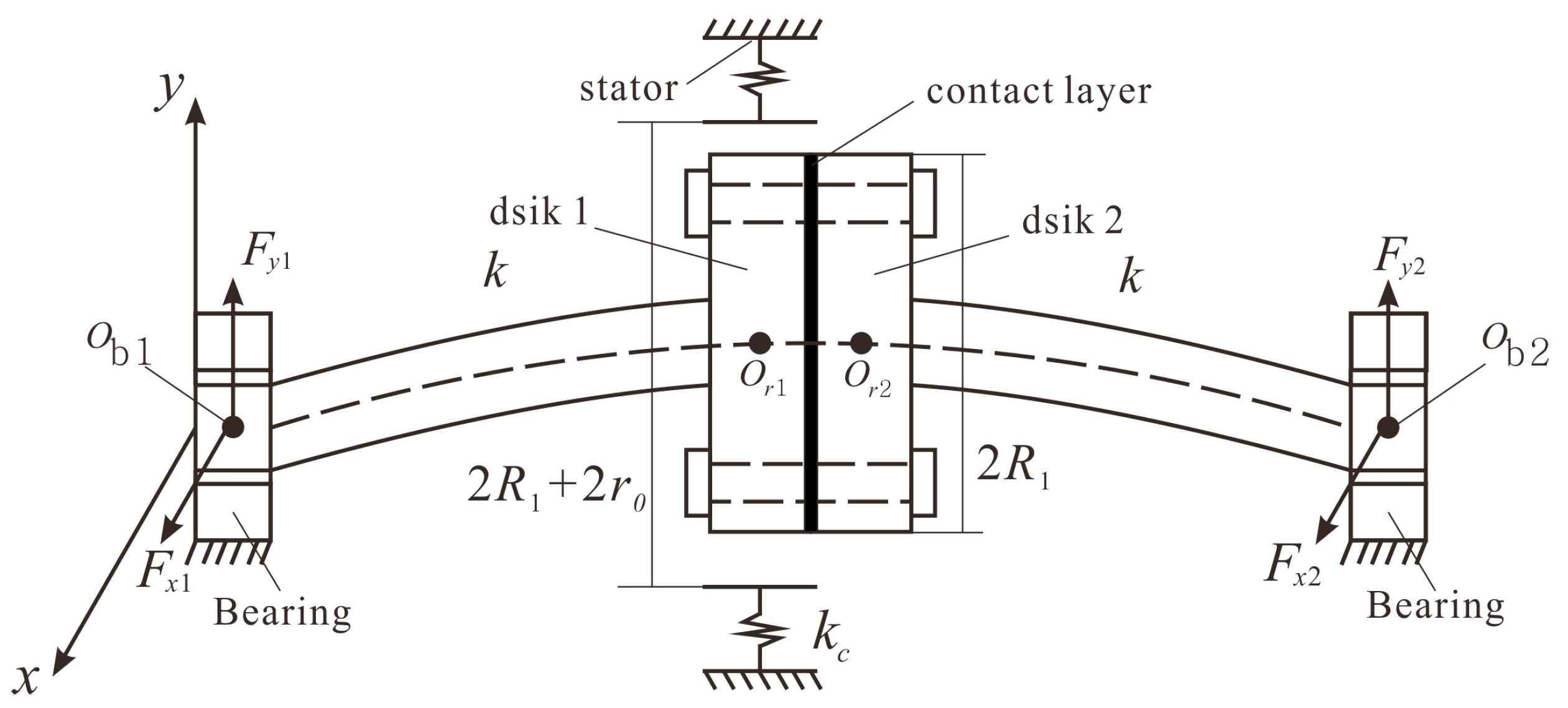
2. Modeling of a Rub-Impact Rod Fastening Rotor System

A schematic of a rub-impact rod fastening rotor bearing system with initial permanent deflection is shown in Figure 1. The lumped mass in journal bearings are mb1 and mb2, m1 and m2 are the lumped mass of two disks, e1 and e2 are the eccentric distance of two disks, and φ is the angle between unbalance mass of the two disks. The stiffness of shaft is k, c1 and c2 are the damping coefficient in the journal bearing and disks, and the damping coefficient in contact layer is c3, δ0 is initial deflection. The dynamic model of the rod fastening rotor under rub-impact and initial permanent deflection is simplified with following assumptions: (1) the effects of rods and contacts on the system response are modeled as a flexural spring with nonlinear stiffness; (2) the shaft connecting the bearing and disk is flexible massless, and only lateral vibration is considered in the model; (3) the rod fastening rotor is supported by identical oil-film bearings at both sides, and the nonlinear oil-film force of the journal bearing is satisfied with the theory of short bearing; and (4) the rub-impact between disk 1 and stator is elastic, the radial deformation is elastic deformation, and the tangential friction force meets the Coulomb friction law.

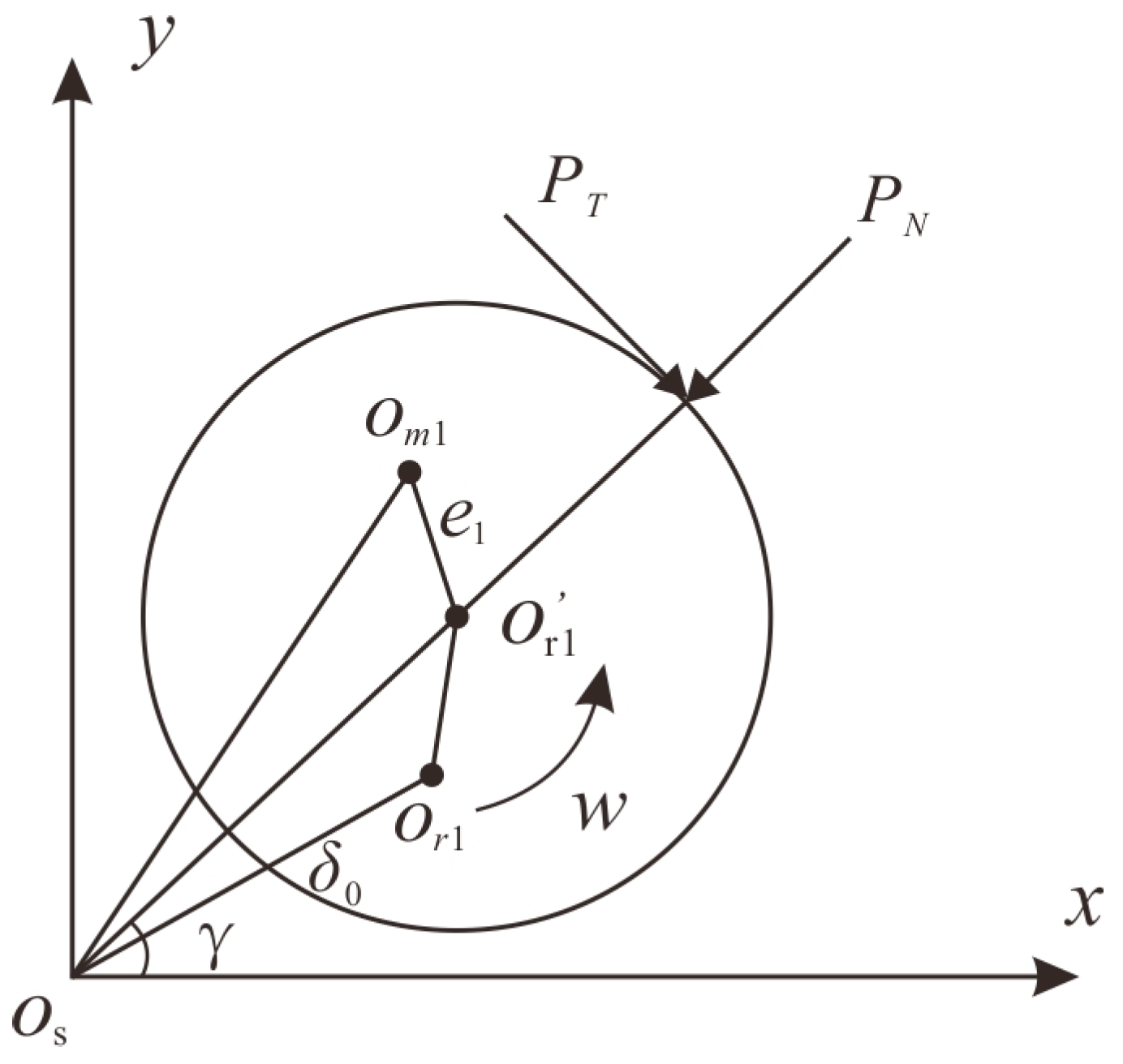
2.1. Rub-Impact Force

Figure 2 is the schematic of a rub-impact forces model with an initial clearance r0 between disk 1 and stator. Os is the stator center, Or1′ is the geometric center of disk 1, Or1 is the initial geometric center of disk 1.
The radial impact force PN can be expressed following linear elastic deformation theory. The tangential rub force PT can be represented following Coulomb law [9]:
{ P N = k c ( r r 0 ) P T = η P N ( r r 0 ) ,
where r is the radial displacement of the disk 1, r = x 1 2 + y 1 2 , kc is the radial stiffness of the stator, and η is the friction coefficient.
The radial impact force PN and the tangential rub force PT can be written in x-y coordinates as
{ P x P y } = [ cos γ sin γ sin γ cos γ ] { P N P T } = k c ( r r 0 ) r [ 1 η η 1 ] { x 1 y 1 } ( r r 0 ) P x = P y = 0    ( r < r 0 ) .
Taking X1 = x1/c, Y1 = y1/c, c is radial clearance of the bearing. Equation (2) can be rewritten as:
{ P X P Y } = [ cos γ sin γ sin γ cos γ ] { P N P T } = c k c ( r r 0 ) r [ 1 η η 1 ] { X 1 Y 1 } ( r r 0 ) P X = P Y = 0    ( r < r 0 ) .

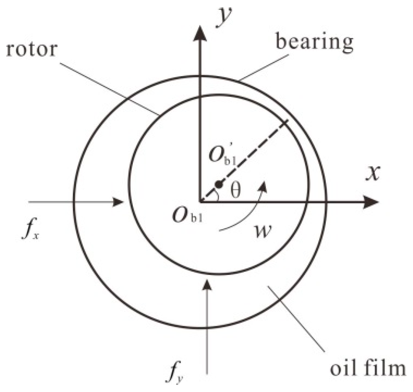
2.2. Nonlinear Oil-Film Force

The capone nonlinear oil-film force model [29] has been proved as an effective model in calculating the nonlinear oil-film force. It is assumed that lubricating oil is isothermal, laminar flow and lubricant dynamic viscosity are constant, and lubricating oil is an incompressible fluid.
The oil-film bearing is shown in Figure 3. According to the Reynolds equation, the dimensionless oil-film pressure distribution is expressed as follows [30]:
( R L ) 2 Z ( h 3 p Z ) = X sin θ Y cos θ 2 ( X ˙ cos θ + Y ˙ sin θ ) ,
where X and Y are dimensionless displacements of journal bearing center respectively, X = x/c, Y = y/c. Z is the dimensionless axial displacement of the journal center, and c is the radial clearance of bearing. p is the dimensionless pressure, h is the thickness of oil-film, R is radius of bearing, and L is the length of the bearing.
The dimensionless pressure p can be obtained by integrating Equation (4):
p = 1 8 ( L R ) 2 ( X 2 Y ˙ ) sin θ ( Y + 2 X ˙ ) cos θ ( 1 X cos θ Y sin θ ) 3 ( 4 Z 2 1 ) .
The nonlinear oil-film force in the x-direction and y-direction can be obtained with Equation (5) through integration along the lubricated arc of bearing:
{ f x f y } = 1 δ P { F x F y } = [ ( X 2 Y ˙ ) 2 + ( Y + 2 X ˙ ) 2 ] 1 / 2 1 X 2 Y 2 × { 3 X V ( X , Y , α ) sin α G ( X , Y , α ) 2 cos α S ( X , Y , α ) 3 Y V ( X , Y , α ) + cos α G ( X , Y , α ) 2 sin α S ( X , Y , α ) }
where δ is the Sommerfeld correction coefficient, δ = μ ω R L P ( R c ) 2 ( L 2 R ) 2 , μ is oil viscosity, ω is the excitation frequency, and P is the half mass of the disk. V ( X , Y , α ) , S ( X , Y , α ) , G ( X , Y , α ) , α are expressed as follows:
V ( X , Y , α ) = 2 + ( Y cos α X sin α ) G ( X , Y , α ) 1 X 2 Y 2 ,
S ( X , Y , α ) = X cos α + Y sin α 1 ( X cos α + Y sin α ) 2 ,
G ( X , Y , α ) = 2 ( 1 X 2 Y 2 ) 1 / 2 [ π 2 + arctan Y cos α X sin α ( 1 X 2 Y 2 ) 1 / 2 ] ,
α = arctan Y + 2 X ˙ X 2 Y ˙ π 2 s i g n [ Y + 2 X ˙ X 2 Y ˙ ] π 2 s i g n ( Y + 2 X ˙ ) .

2.3. The Governing Equations of Motion

According to the D’Alembert principle, the governing motion equations of the rod fastening rotor under rub-impact and initial permanent deflection can be written as:
{ m b 1 x ¨ b 1 + c 1 x ˙ b 1 + k ( x b 1 x 1 ) = F x ( x b 1 , y b 1 , x ˙ b 1 , y ˙ b 1 ) m b 1 y ¨ b 1 + c 1 y ˙ b 1 + k ( y b 1 y 1 ) = F y ( x b 1 , y b 1 , x ˙ b 1 , y ˙ b 1 ) m b 1 g m 1 x ¨ 1 + c 2 x ˙ 1 + c 3 ( x ˙ 1 x ˙ 2 ) + k ( x 1 x b 1 ) + F c x 1 = m 1 e 1 ω 2 cos ω t + k δ 0 cos ( ω t + β ) + P x m 1 y ¨ 1 + c 2 y ˙ 1 + c 3 ( y ˙ 1 y ˙ 2 ) + k ( y 1 y b 1 ) + F c y 1 = m 1 e 1 ω 2 sin ω t + k δ 0 sin ( ω t + β ) m 1 g + P y m 2 x ¨ 2 + c 2 x ˙ 2 + c 3 ( x ˙ 2 x ˙ 1 ) + k ( x 2 x b 2 ) + F c x 2 = m 2 e 2 ω 2 cos ( ω t + ϕ ) + k δ 0 cos ( ω t + β ) m 2 y ¨ 2 + c 2 y ˙ 2 + c 3 ( y ˙ 2 y ˙ 1 ) + k ( y 2 y b 2 ) + F c y 2 = m 2 e 2 ω 2 sin ( ω t + ϕ ) + k δ 0 sin ( ω t + β ) m 2 g m b 2 x ¨ b 2 + c 1 x ˙ b 2 + k ( x b 2 x 2 ) = F x ( x b 2 , y b 2 , x ˙ b 2 , y ˙ b 2 ) m b 2 y ¨ b 2 + c 1 y ˙ b 2 + k ( y b 2 y 2 ) = F y ( x b 2 , y b 2 , x ˙ b 2 , y ˙ b 2 ) m b 2 g ,
where Fx and Fy are the nonlinear oil-film force in the x-direction and y-direction, Px and Py are the rub-impact force in the x-direction and y-direction, φ is the angle between mass eccentricity of the two disks, and β is the phase angle between the mass eccentricity and the initial permanent deflection. Fcx1, Fcy1, Fcx2, Fcy2 are the nonlinear restoring forces of contact layer, the expressions are as the following:
{ F c x 1 = F c x 2 = k 1 ( x 1 x 2 ) + k 1 ( x 1 x 2 ) 3 F c y 1 = F c y 2 = k 1 ( y 1 y 2 ) + k 1 ( y 1 y 2 ) 3 ,
where k1 is the linear contact stiffness, and k1′ is the nonlinear contact stiffness.
Substituting the dimensionless oil-film force and rub-impact force into Equation (11), the dimensionless motion equation of the system can be obtained:
{ X ¨ b 1 + c 1 m b 1 ω X ˙ b 1 + k m b 1 ω 2 ( X b 1 X 1 ) = δ P m b 1 c ω 2 f x ( X b 1 , Y b 1 , X ˙ b 1 , Y ˙ b 1 ) Y ¨ b 1 + c 1 m b 1 ω Y ˙ b 1 + k m b 1 ω 2 ( Y b 1 Y 1 ) = δ P m b 1 c ω 2 f y ( X b 1 , Y b 1 , X ˙ b 1 , Y ˙ b 1 ) g c ω 2 X ¨ 1 + c 2 m 1 ω X ˙ 1 + c 3 m 1 ω ( X ˙ 1 X ˙ 2 ) + k m 1 ω 2 ( X 1 X b 1 ) + F c x 1 m 1 c ω 2 = e 1 c cos ( τ ) + k δ 0 m 1 c ω 2 cos ( τ + β ) + P X m 1 c ω 2 Y ¨ 1 + c 2 m 1 ω Y ˙ 1 + c 3 m 1 ω ( Y ˙ 1 Y ˙ 2 ) + k m 1 ω 2 ( Y 1 Y b 1 ) + F c y 1 m 1 c ω 2 = e 1 c sin ( τ ) + k δ 0 m 1 c ω 2 sin ( τ + β ) g c ω 2 + P Y m 1 c ω 2 X ¨ 2 + c 2 m 2 ω X ˙ 2 + c 3 m 2 ω ( X ˙ 2 X ˙ 1 ) + k m 2 ω 2 ( X 2 X b 2 ) + F c x 2 m 2 c ω 2 = e 2 c cos ( τ + ϕ ) + k δ 0 m 2 c ω 2 cos ( τ + β ) Y ¨ 2 + c 2 m 2 ω Y ˙ 2 + c 3 m 2 ω ( Y ˙ 2 Y ˙ 1 ) + k m 2 ω 2 ( Y 2 Y b 2 ) + F c y 2 m 2 c ω 2 = e 2 c sin ( τ + ϕ ) + k δ 0 m 2 c ω 2 sin ( τ + β ) g c ω 2 X ¨ b 2 + c 1 m b 2 ω X ˙ b 2 + k m b 2 ω 2 ( X b 2 X 2 ) = δ P m b 2 c ω 2 f x ( X b 2 , Y b 2 , X ˙ b 2 , Y ˙ b 2 ) Y ¨ b 2 + c 1 m b 2 ω Y ˙ b 2 + k m b 2 ω 2 ( Y b 2 Y 2 ) = δ P m b 2 c ω 2 f y ( X b 2 , Y b 2 , X ˙ b 2 , Y ˙ b 2 ) g c ω 2 ,
where τ is dimensionless time, τ = ωt, Xb1 = xb1/c, Xb2 = xb2/c, Yb1 = yb1/c, Yb2 = yb2/c, X1 = x1/c, X2 = x2/c, Y1 = y1/c, and Y2 = y2/c.

3. Numerical Results and Discussion

The parameters of the rod fastening rotor system are: mb1 = 4 kg, mb2 = 4 kg, m1 = 32.1 kg, m2 = 32.1 kg, c1 = 1050 N·s/m, c2 = 2100 N·s/m, c3 = 2100 N·s/m, k = 2.5 × 10⁷ N/m, k1 = 2.5 × 10⁷ N/m, k1′ = 2.5 × 10⁷ N/m, kc = 1 × 10⁷ N/m, r0 = 0.18 mm, e1 = 0.05 mm, e2 = 0.05 mm, δ0 = 0.01 mm, β = π/4, η = 0.1, φ = 0, R = 25 mm, L = 12 mm, c = 0.11 mm, μ = 0.018 Pa·s, and g = 9.81 m/s2. Assuming that the rod fastening rotor has rigid support, the natural frequency ωc = (k/m1)1/2 = 882 rad/s. In fact, the rotor cannot have complete rigid support, and the critical speed should be less than 882 rad/s. The coupled nonlinear dynamic analysis of a rod fastening rotor under rub-impact and initial permanent deflection is carried out by the fourth-order Runge–Kutta method. The period of the dimensionless system is 2π; the integral step length of each period is 1/100; the calculation is 200 periods; we choose the last 100 periods as the effective analysis data; and the number of the effective data points is 10,000. Bifurcation diagram, vibration waveform, frequency spectrum, shaft orbit and Poincaré map are presented to illustrate the nonlinear dynamic phenomena of system as follows.

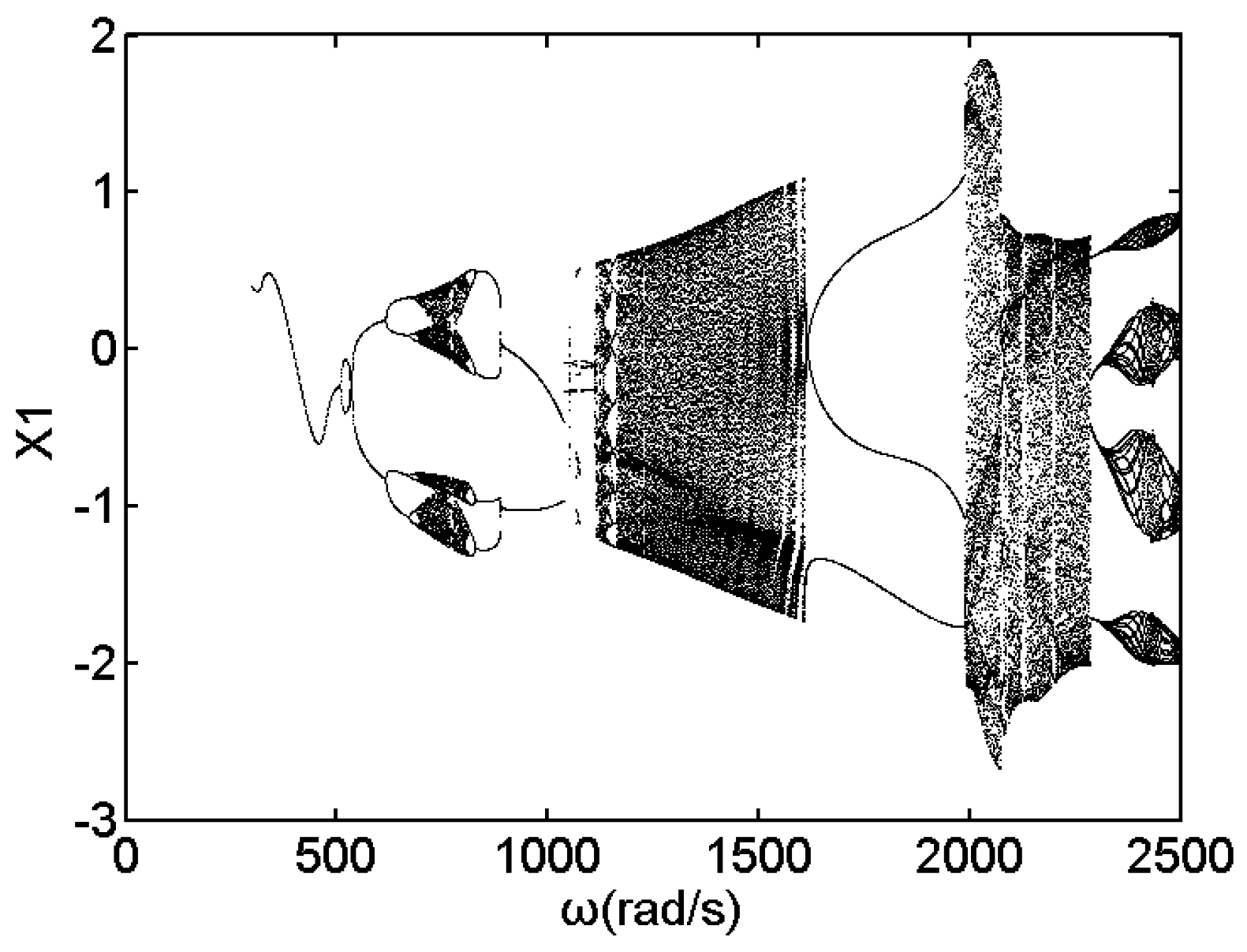
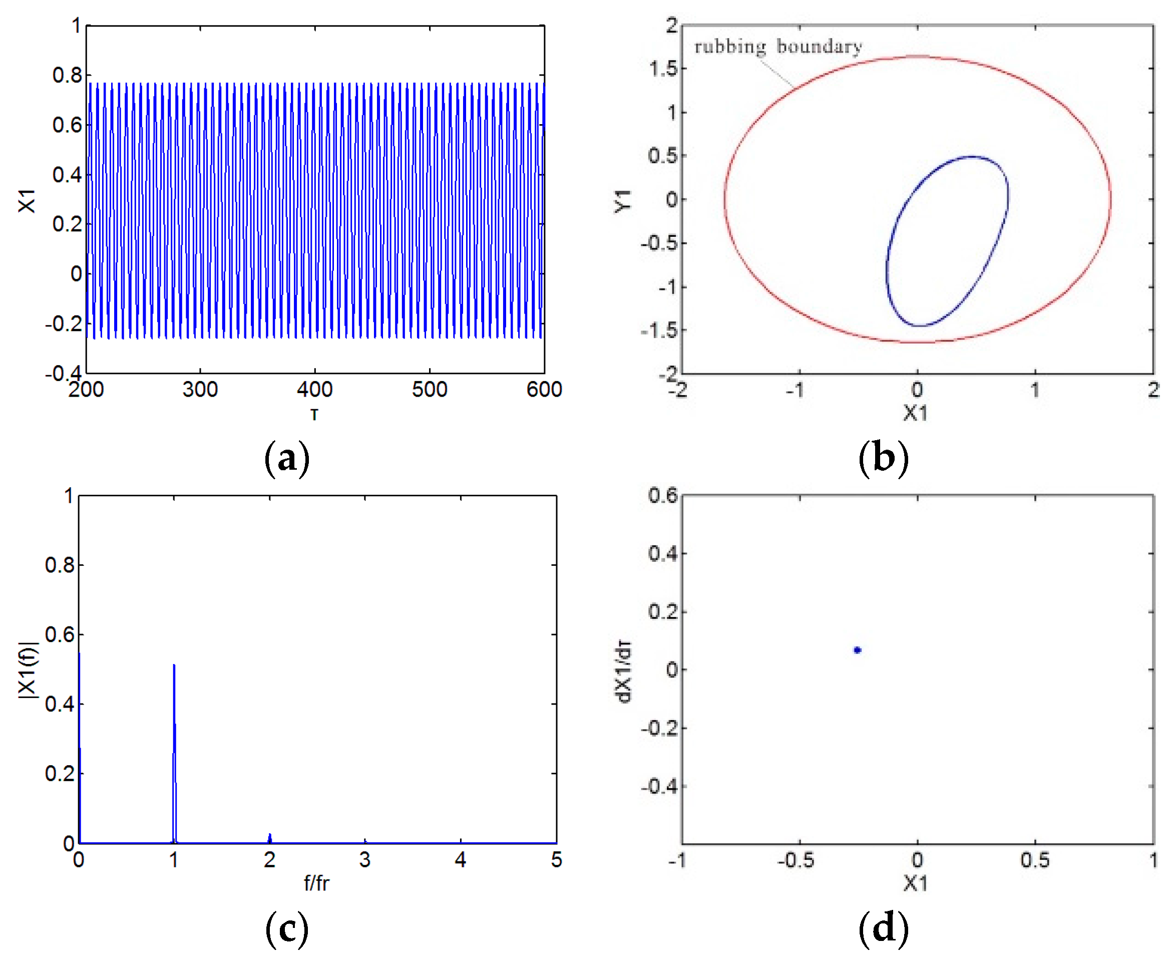
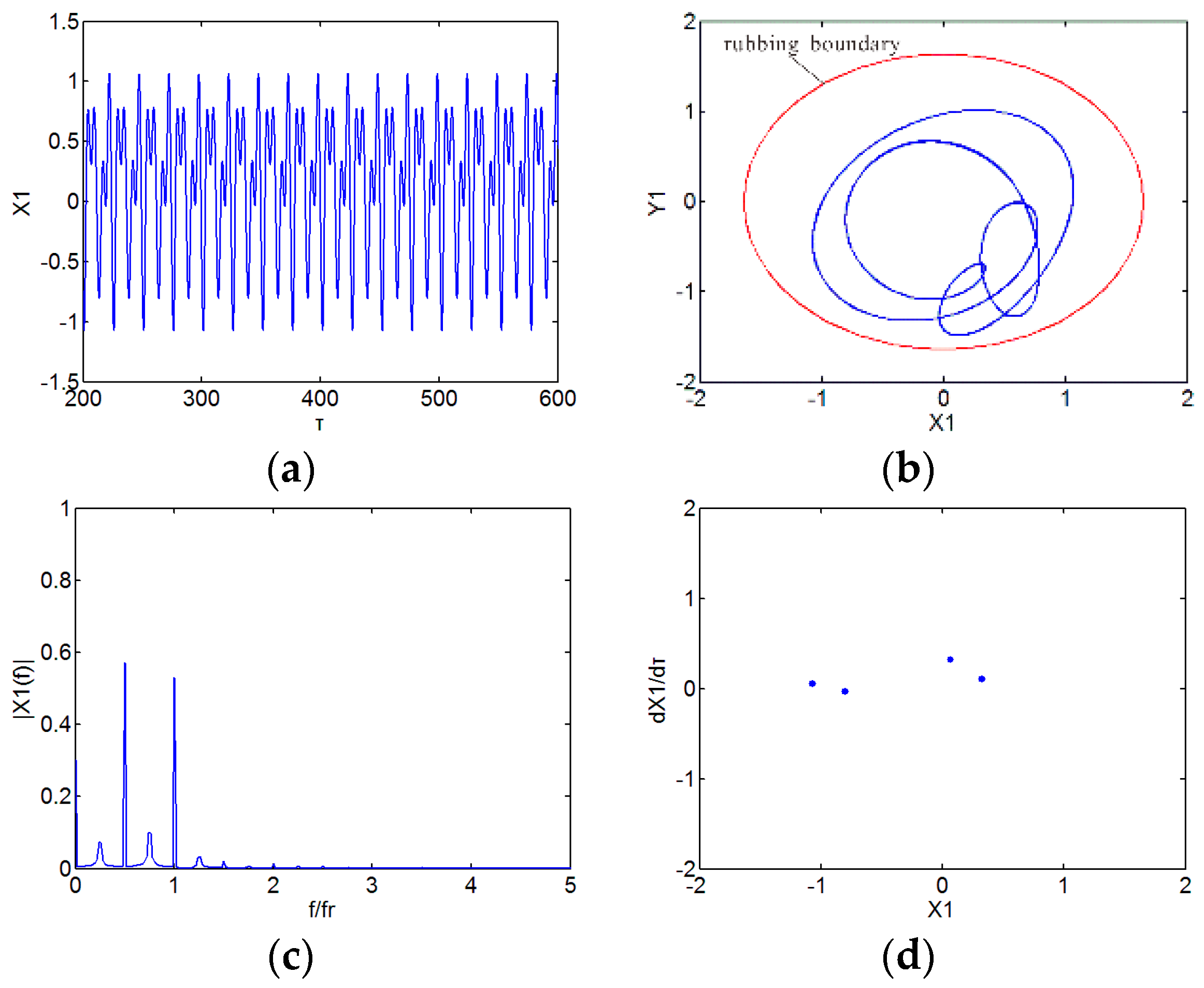
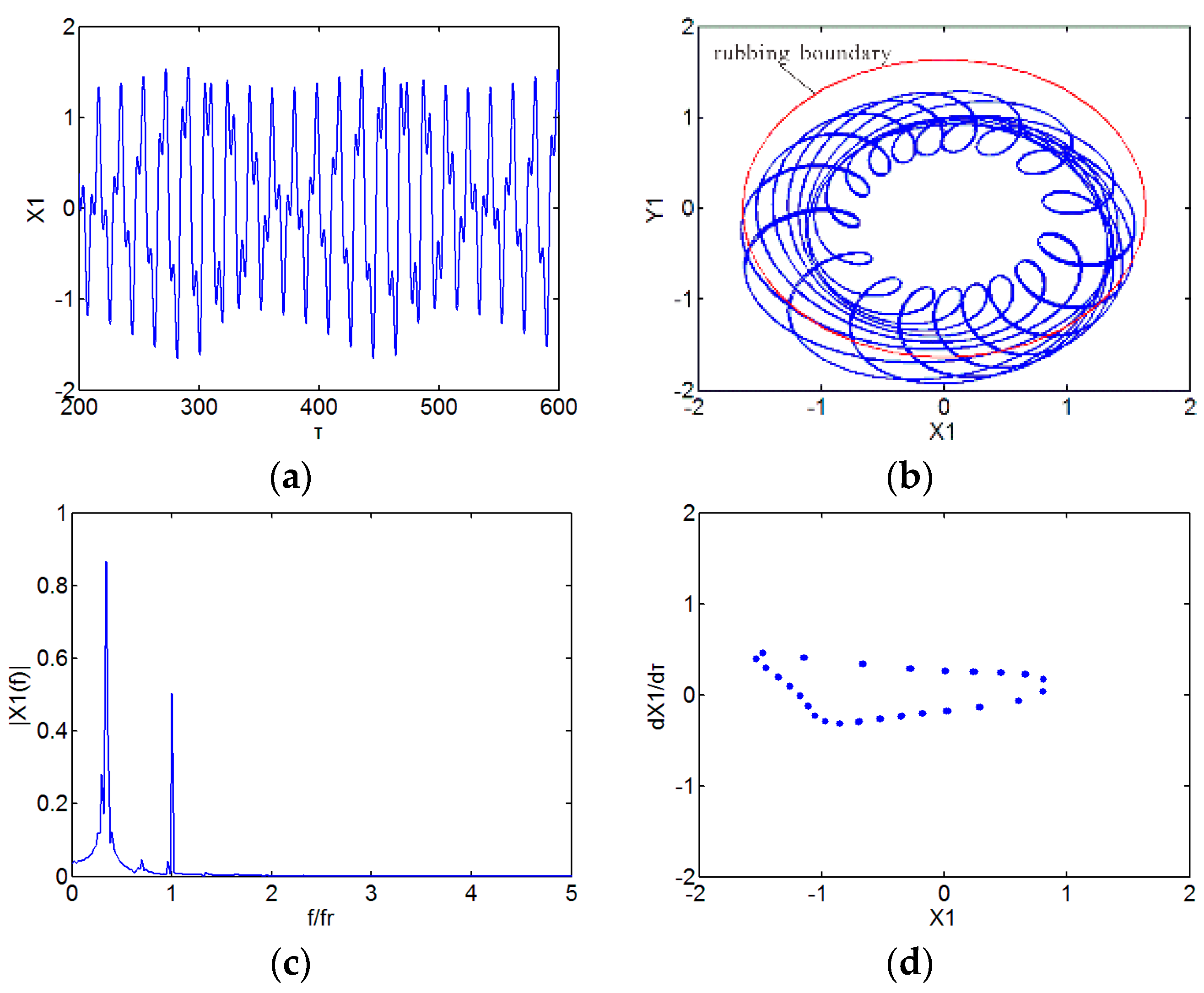
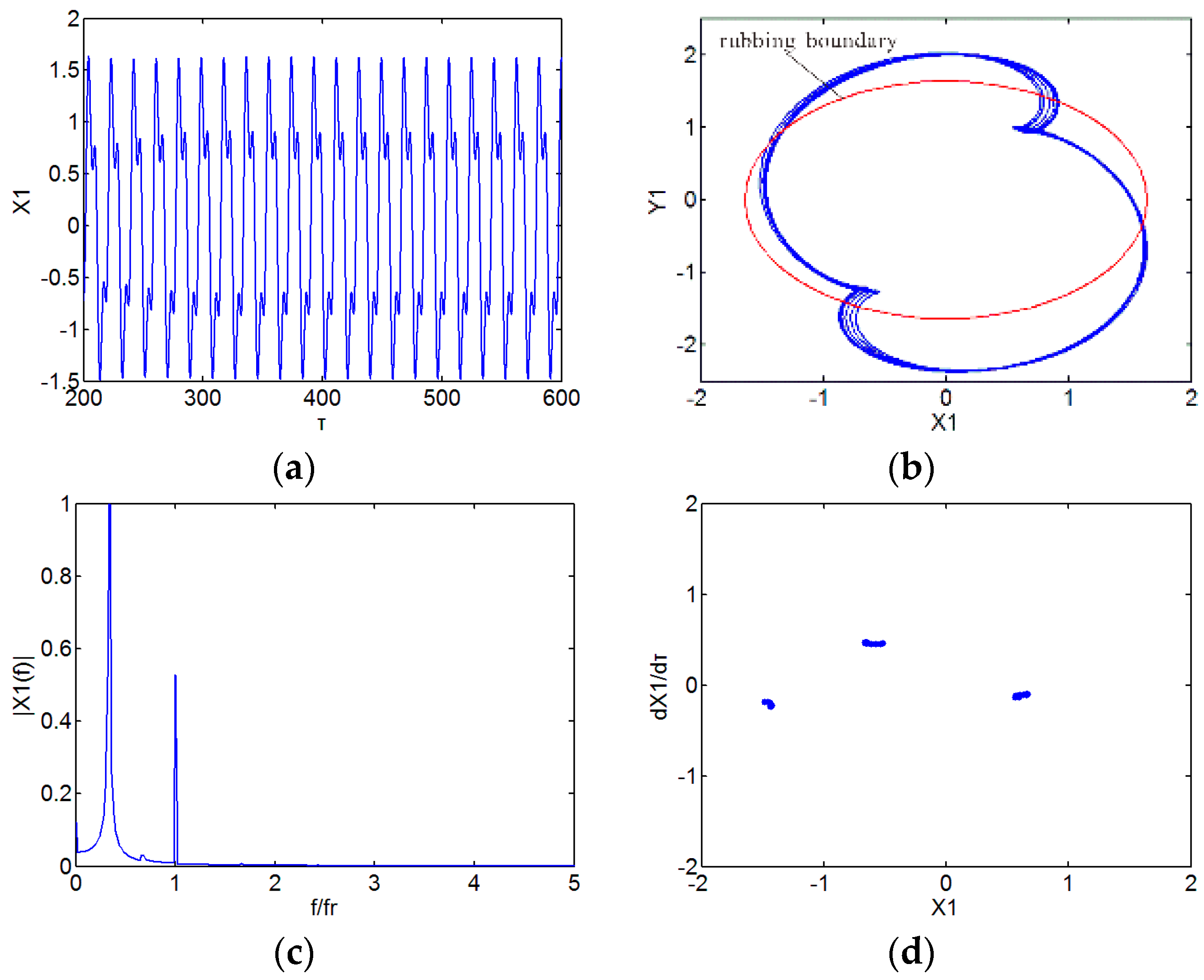
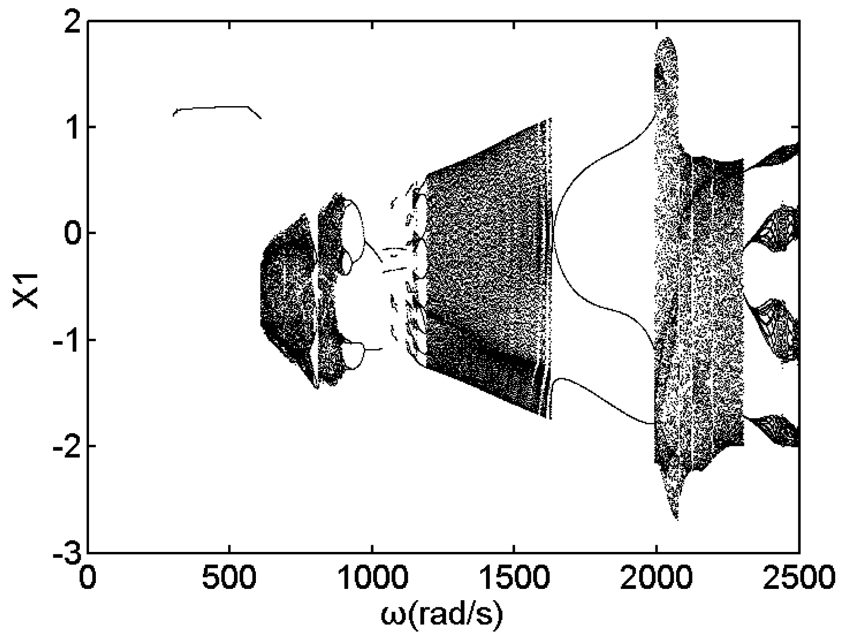
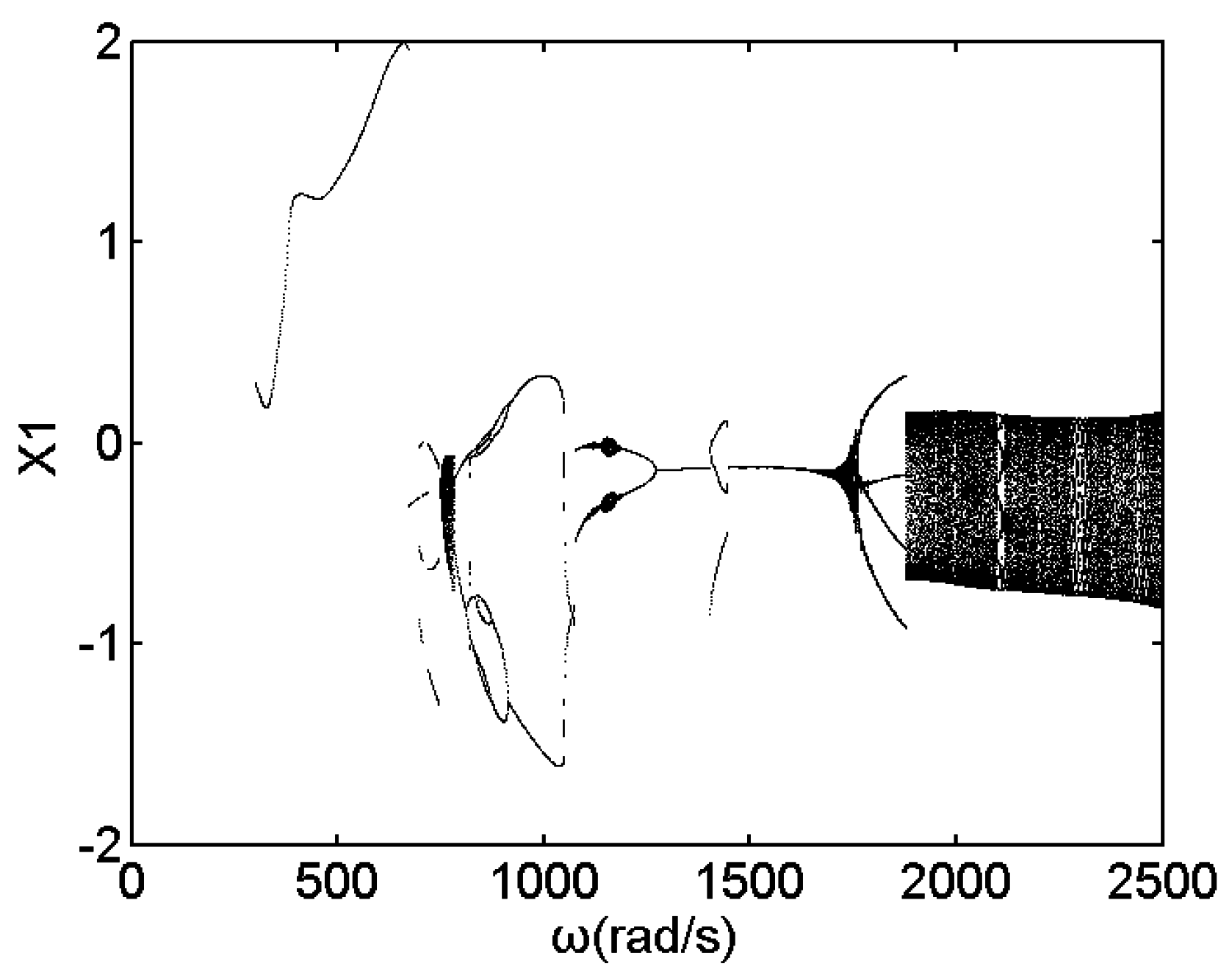
3.1. Effect of Speed

The dynamic responses and system status vary with the increase of rotating speed. Bifurcation diagram can clearly reflect the relationship of the system status varying with parameters.
Taking rotating speed as control parameter, Figure 4 shows the bifurcation diagram of an integral rotor bearing system in a horizontal direction of disk center without considering the initial permanent deflection and contact characteristics between disks. The system keeps synchronous period-1 motion at ω < 507 rad/s. With the increasing of rotating speed, the system response exhibits a rich nonlinear dynamic diversity.
Figure 5 shows the bifurcation diagram of a rub-impact rod fastening rotor bearing system at δ0 = 0, kc = 1 × 10⁷ N/m. The system response has a big difference in high rotating speed compared with Figure 4. When ω < 507 rad/s, the system state is synchronous periodic-1 motion. It can be seen from Figure 6 that there is one isolated point in the Poincaré map and one-peak amplitude in the frequency spectrum, and the rub-impact does not occur under this condition. The system turns into periodic-2 motion at ω = 507 rad/s. With the increase of rotating speed, the period doubling bifurcation occurs. The periodic-2 motion, periodic-4 motion, periodic-8 motion and chaotic motion are observed one by one. Figure 7 shows the periodic-4 motion at ω = 670 rad/s, the Poincaré map contains four isolated points, the amplitude of half fundamental frequency exceeds the amplitude of fundamental frequency, and the oil whirl occurs at this rotating speed. When ω > 810 rad/s, inverse period doubling bifurcation occurs. The quasi-periodic motion can be observed at the interval of 1038 rad/s < ω < 1615 rad/s, as shown in Figure 8, the Poincaré map of the system presents a closed loop, and the frequency spectrum contains incommensurate frequency components. Meanwhile, the oil whip frequency is less than half of the fundamental frequency, and the amplitude of oil whip frequency is bigger than the amplitude of fundamental frequency. The oil whirl develops into oil whip at this speed, and the shaft orbit exceeds rubbing boundary. When ω > 1615 rad/s, the system experiences periodic-3 motion, and with the increase of rotating speed, the system finally enters into quasi-periodic motion. Figure 9 shows the periodic-3 motion at ω = 1750 rad/s, and the Poincaré map performs three isolated points.
The initial permanent deflection is common among rotor systems. In order to analyze the effect of initial permanent deflection on responses of the rub-impact rod fastening rotor bearing system, the study is carried out by setting δ0 = 0.01 mm, β = π/4. Figure 10 shows the bifurcation diagram of a disk 1 center in a horizontal direction considering the initial permanent deflection in the system motion equations.
Similar to the system response without considering the initial permanent deflection, the system presents a synchronous periodic-1 motion at ω < 608 rad/s (see Figure 11). Compared with Figure 6, shaft orbit exceeds rubbing boundary, and the rub-impact has occurred already at this rotating speed. Under the effect of initial permanent deflection, unbalance force, oil-film force and rub-impact force, the system directly enters into chaotic motion at ω = 608 rad/s. As indicated in Figure 12, the frequency spectrum contains continuous frequency bands, the orbit is irregular, and the Poincaré map presents a strange attractor. When the rotating speed reaches 898 rad/s, the system leaves chaotic motion and undergoes an inverse period doubling bifurcation. Periodic-16 motion, periodic-8 motion, periodic-4 motion and periodic-2 motion occur alternately at the interval of 608 rad/s < ω < 1035 rad/s. With the increase of the rotating speed, the system experiences a transient multi-periodic motion and then enters into quasi-periodic motion. The quasi-periodic motion is illustrated in Figure 13, the Poincaré map of the system presents a closed loop, the frequency spectrum is continuous, and the shaft orbit is irregular. At ω = 1639 rad/s, the system bifurcates into periodic-3 motion (see in Figure 14).
The bifurcation diagram can reveal the motion state of the system varying with rotating speed. It can be concluded from the above analysis that initial permanent deflection has a great influence on the dynamic response of the rub-impact rod fastening rotor bearing system. Comparing Figure 5 with Figure 10, it is obvious that the initial permanent deflection mainly affects the system response at low speed. The oil-film force and unbalance force are small when the system is at a low speed, and initial permanent deflection becomes the main factor affecting the system states. With the increase of rotating speed, the oil-film force and unbalance force gradually increase and begin to play a leading role in the system states. Meanwhile, the rub-impact occurs at a lower speed when initial permanent deflection is considered.

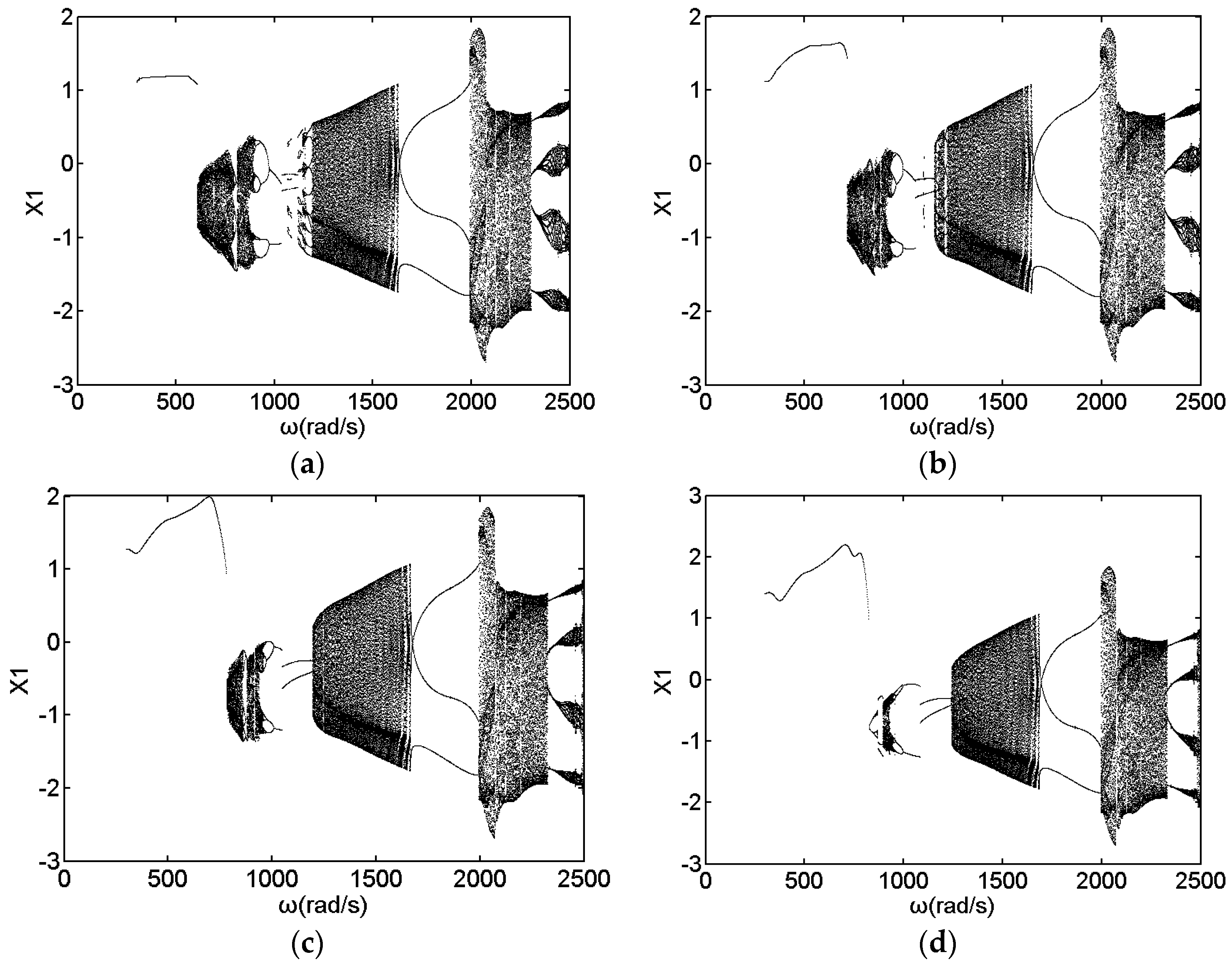
3.2. Effect of Initial Permanent Deflection

The manufacture deviation, unfitting assembly, misalignment and thermal bending can result in the residual shaft bow. In Section 3.1, the results indicate that the initial permanent deflection has a big influence on the system responses. In this part, the effect of different initial permanent deflection length on the dynamic responses of the rub-impact rod fastening rotor bearing system has been discussed.
Taking kc = 1 × 10⁷ N/m, r0 = 0.18 mm, e1 = 0.05 mm, e2 = 0.05 mm, and β = π/4, Figure 15 shows the bifurcation diagrams of the disk 1 center in a horizontal direction under different initial permanent deflection lengths δ0 = 0.01 mm, δ0 = 0.02 mm, δ0 = 0.03 mm, and δ0 = 0.04 mm. As shown in Figure 15a, the system bifurcates into chaotic motion at ω = 608 rad/s and leaves chaotic motion at ω = 898 rad/s, with the increase of rotating speed, the system undergoes an inverse period doubling bifurcation. At the interval of 1639 rad/s < ω < 1991 rad/s, the system keeps periodic-3 motion. When δ0 = 0.02 mm, the system enters into chaotic motion at ω = 716 rad/s and leaves chaotic motion at ω = 936 rad/s, similar to the bifurcation diagram at δ0 = 0.01 mm, with the increase of rotating speed, the system experiences periodic-16 motion,periodic-8 motion,periodic-4 motion,periodic-2 motion, quasi-periodic motion and keeps periodic-3 motion at 1655 rad/s < ω < 1992 rad/s. Figure 15c shows the bifurcation diagram at δ0 = 0.03 mm, and the system bifurcates into chaotic at ω = 782 rad/s. When the rotating speed reaches 962 rad/s, the system undergoes an inverse period doubling bifurcation and leaves chaotic motion. At ω = 1192 rad/s, the system becomes quasi-periodic motion from periodic-2 motion and keeps periodic-3 motion at 1663 rad/s < ω < 1991 rad/s with the increase of rotating speed. As indicated from Figure 15d, the system bifurcates into periodic-2 motion at ω = 826 rad/s and leaves chaotic motion at ω = 948 rad/s. The system presents similar characteristics with the increase of rotating speed compared with δ0 = 0.03 mm.
It can be seen from Figure 15 that the system bifurcation diagrams under different initial permanent deflection length δ0 do not present an obvious differences in high-speed regions. In a low-speed region, the system keeps periodic-1 motion under different initial permanent deflection lengths. The instability speed of the system gradually rises with the increase of initial permanent deflection length. Meanwhile, the chaotic motion region becomes smaller and smaller. Although the instability speed of the system increased with the value of initial permanent deflection length δ0, the initial permanent deflection is not expected.

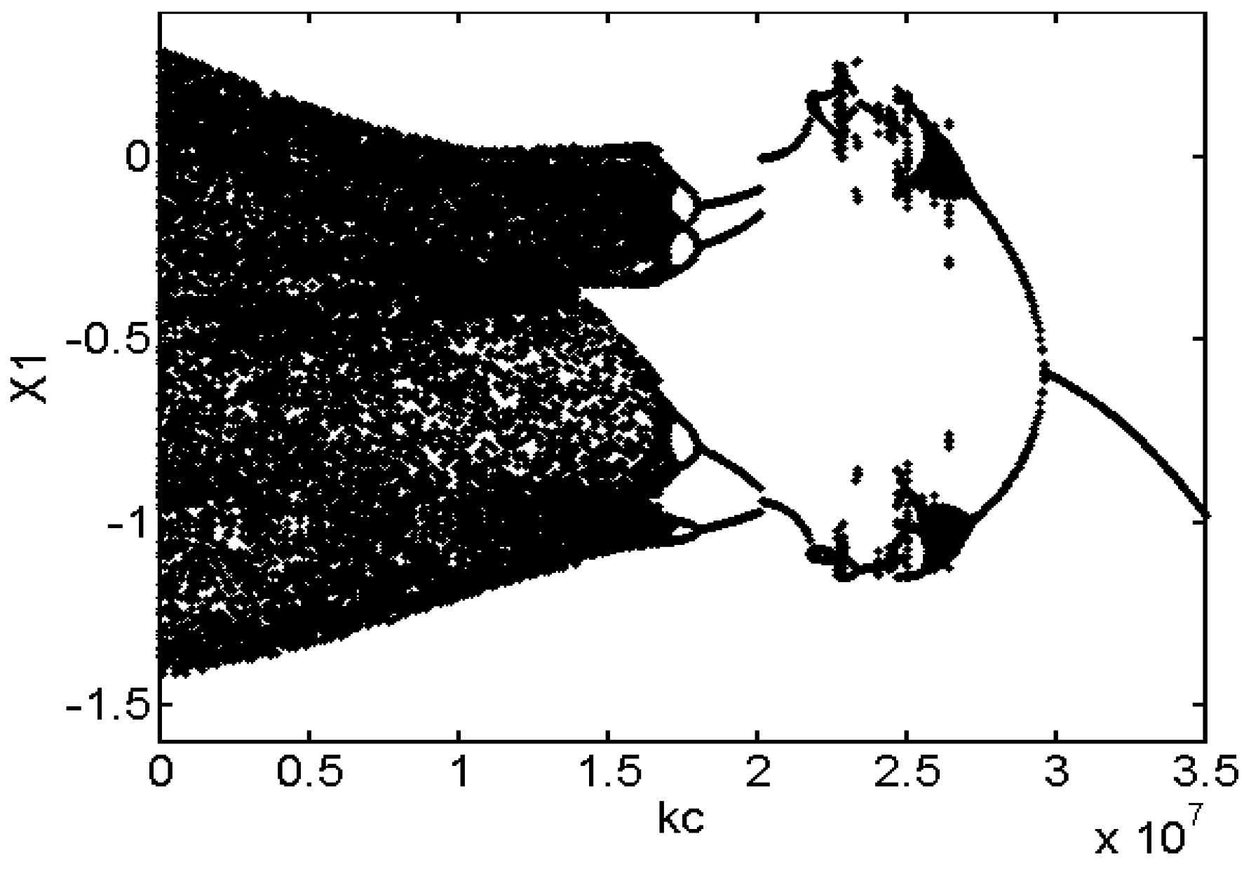
3.3. Effect of Radial Stiffness of the Stator

Radial stiffness of the stator is an important factor of a rub-impact rotor bearing system. In this part, the influence of radial stiffness of the stator is discussed under certain conditions. Taking radial stiffness of the stator as the control parameter, Figure 16 shows the bifurcation diagram of disk 1 center in a horizontal direction at ω = 826 rad/s, r0 = 0.11 mm, δ0 = 0.01 mm.
It can be seen from Figure 16 that the system states vary with the increase of the radial stiffness of the stator. When the stiffness is small, the rub-impact force is far less than oil-film force, and the system response is mainly decided by the oil-film force and initial permanent deflection. The system presents chaotic motion at kc = [0–1.71 × 10⁷] N/m. As shown in Figure 17, the orbit is irregular, the Poincaré map presents a strange attractor, and the frequency spectrum contains continuous frequency bands. Meanwhile, there is a half fundamental frequency component in the frequency spectrum, and oil whirl occurs at this condition. With the increase of radial stiffness of stator kc, the system experiences periodic-8 motion, periodic-4 motion, and periodic-2 motion. Figure 18 shows the periodic-4 motion at kc = 1.9 × 10⁷ N/m, and there are four isolated points in Poincaré map. At kc = [2.19 × 10⁷–2.73 × 10⁷] N/m, the system undergoes multi-periodic motions and returns back to periodic-2 motion at kc = 2.73 × 10⁷ N/m (see in Figure 19). When kc > 2.97 × 10⁷ N/m, the system displays a synchronous periodic-1 motion, and the oil whirl disappears under this condition (see in Figure 20).
The radial stiffness of the stator has a great influence on the responses of a rub-impact rod fastening rotor bearing system under initial permanent deflection. With the increase of radial stiffness for the stator, the system response becomes simpler under certain conditions. Meanwhile, the oil whirl is weaker or even disappears at a certain rotating speed.

4. Conclusions

The dynamic motion equations of a rod fastening rotor bearing system under rub-impact and initial permanent deflection is derived based on the D’Alembert principle. The coupled nonlinear dynamic characteristics of the rod fastening rotor bearing system under rub-impact and initial permanent deflection have been investigated. The effect of radial stiffness for the stator, initial permanent deflection length and rotating speed on the dynamic characteristics of the rod fastening rotor bearing system are investigated in detail. The following conclusions can be obtained from the above analysis:
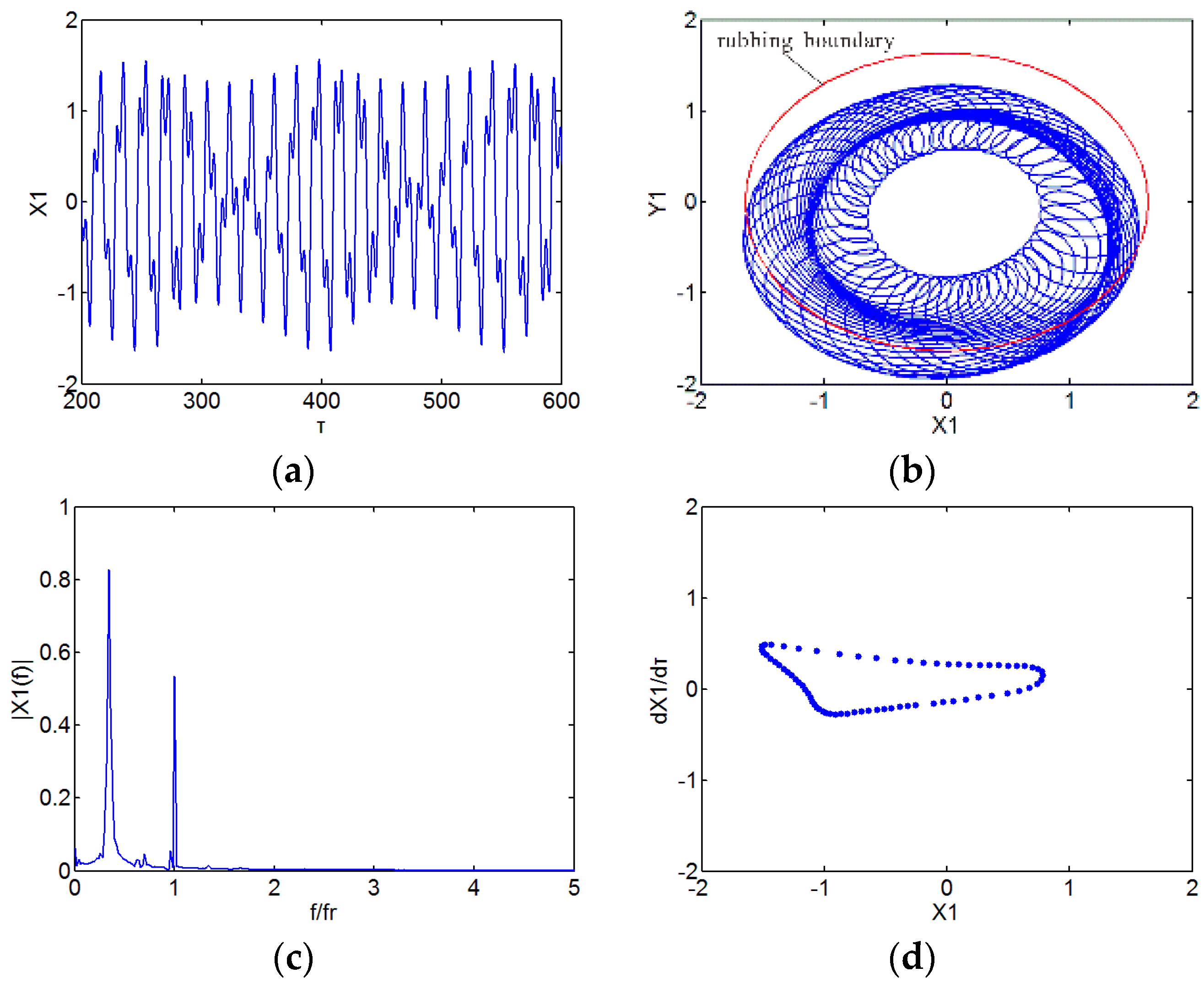
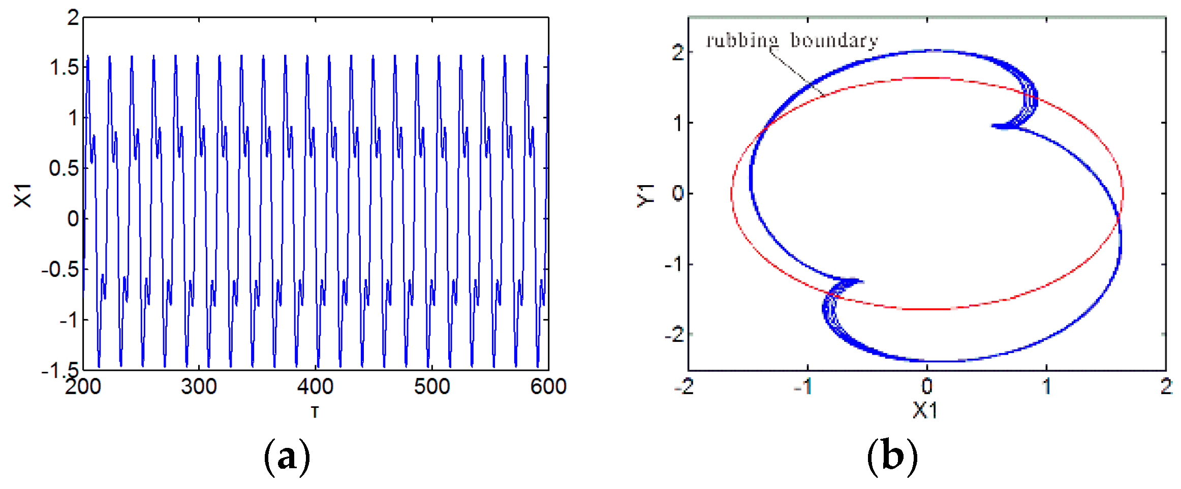
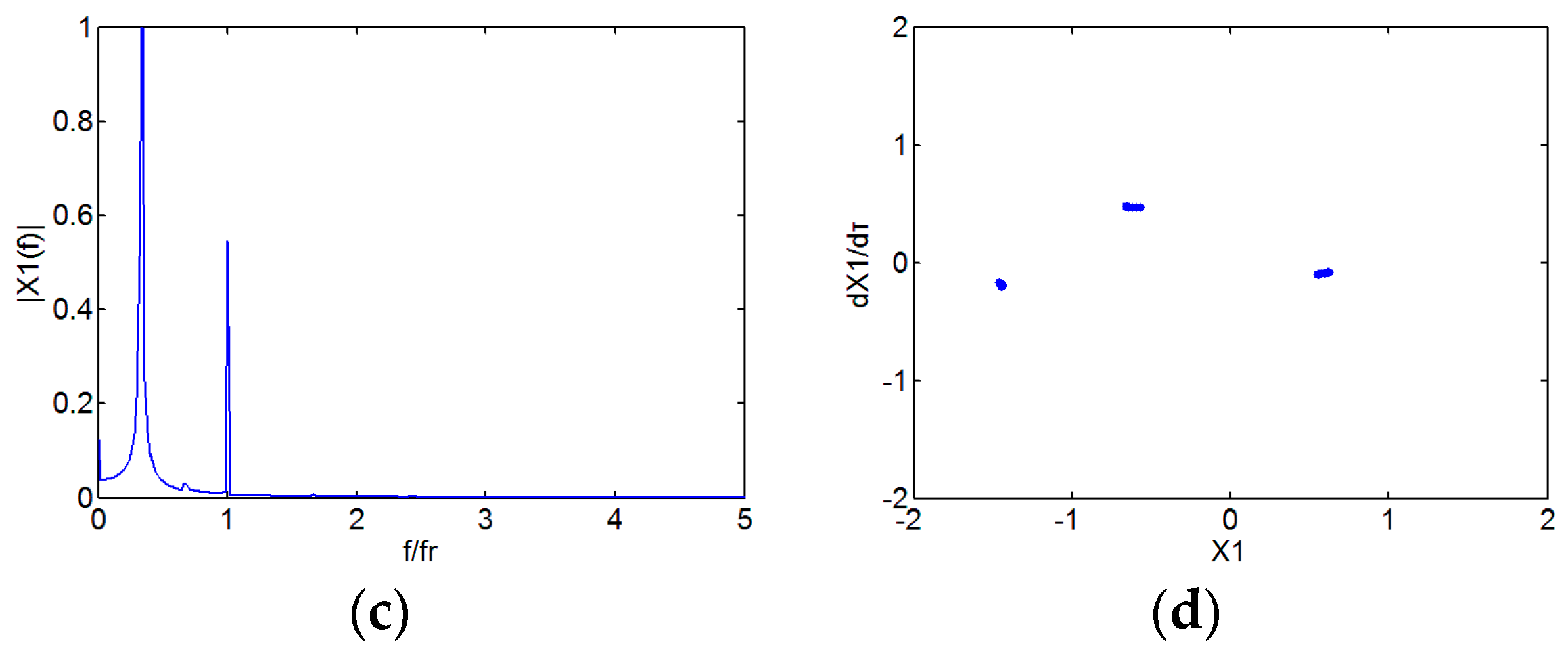
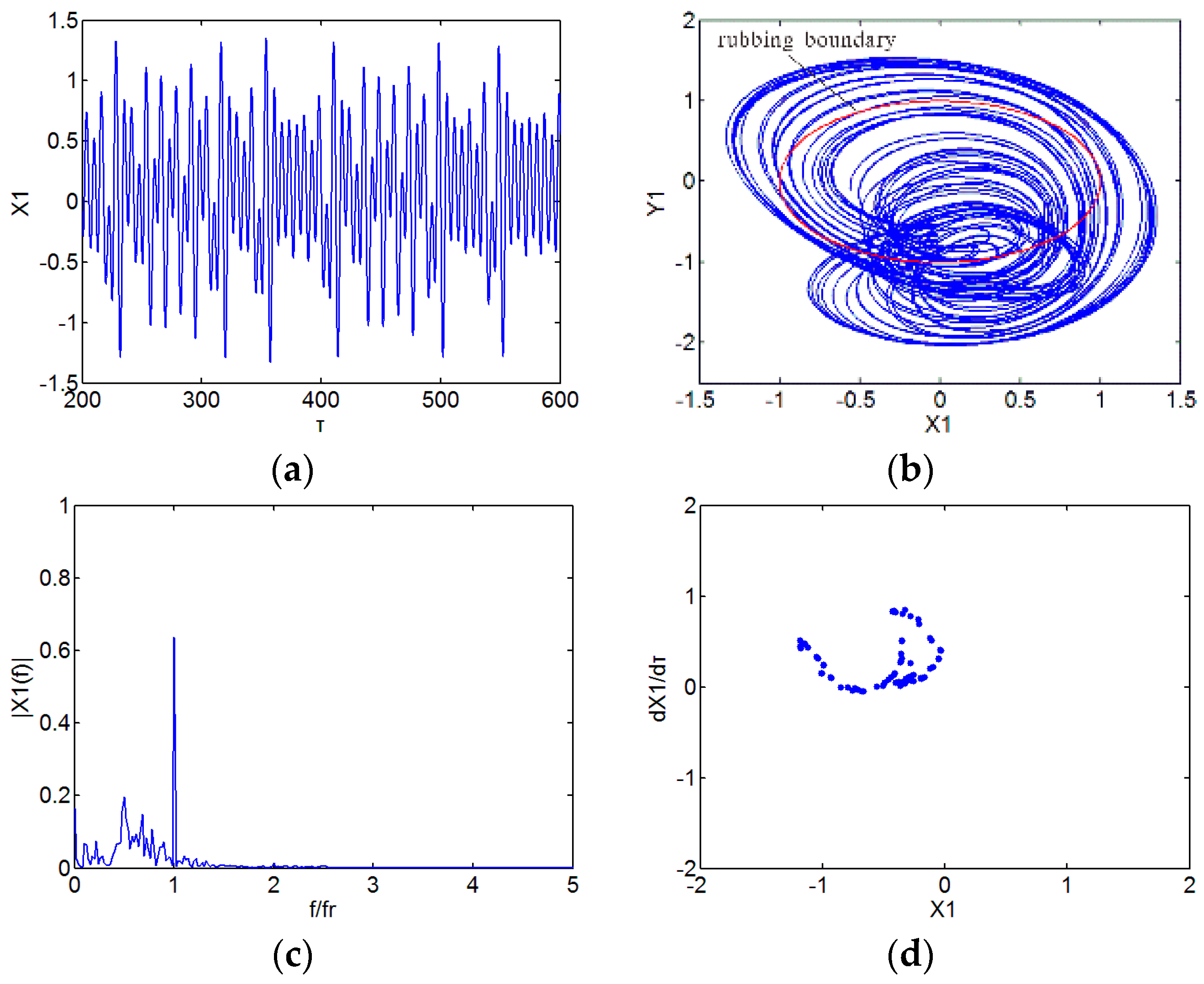
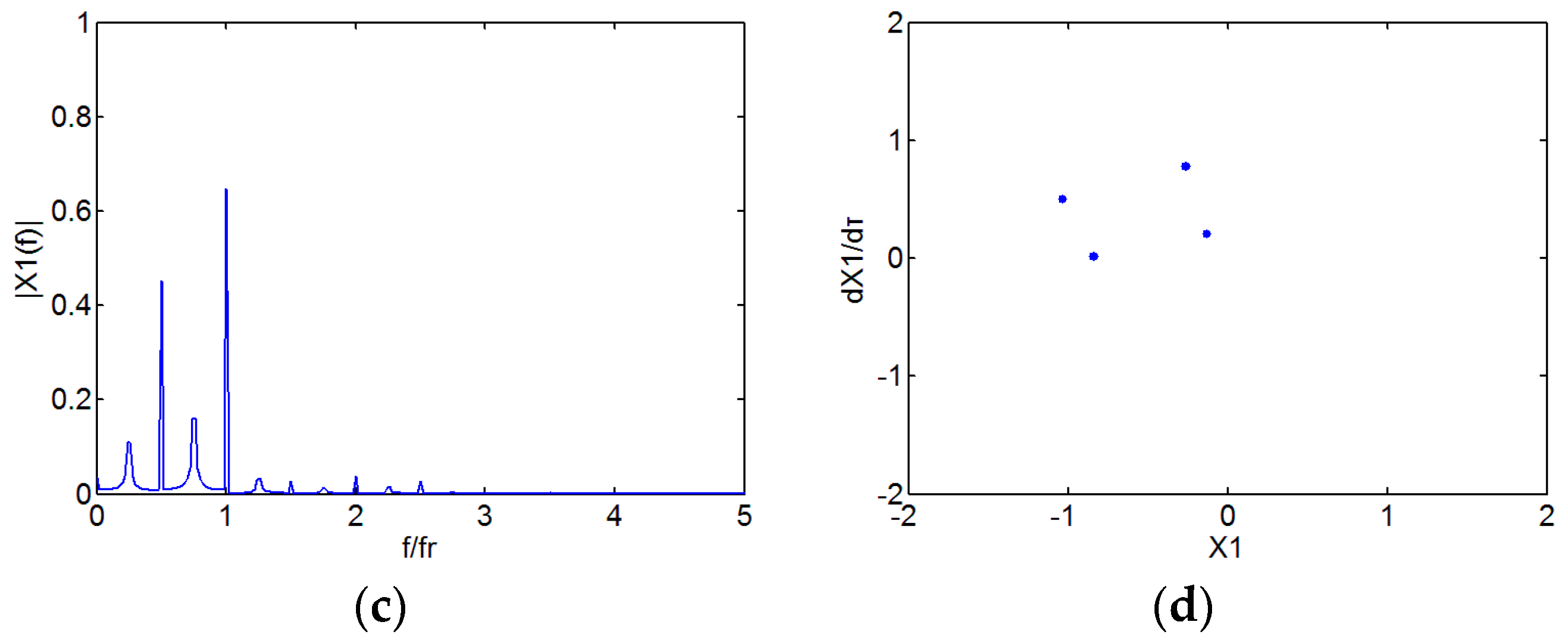
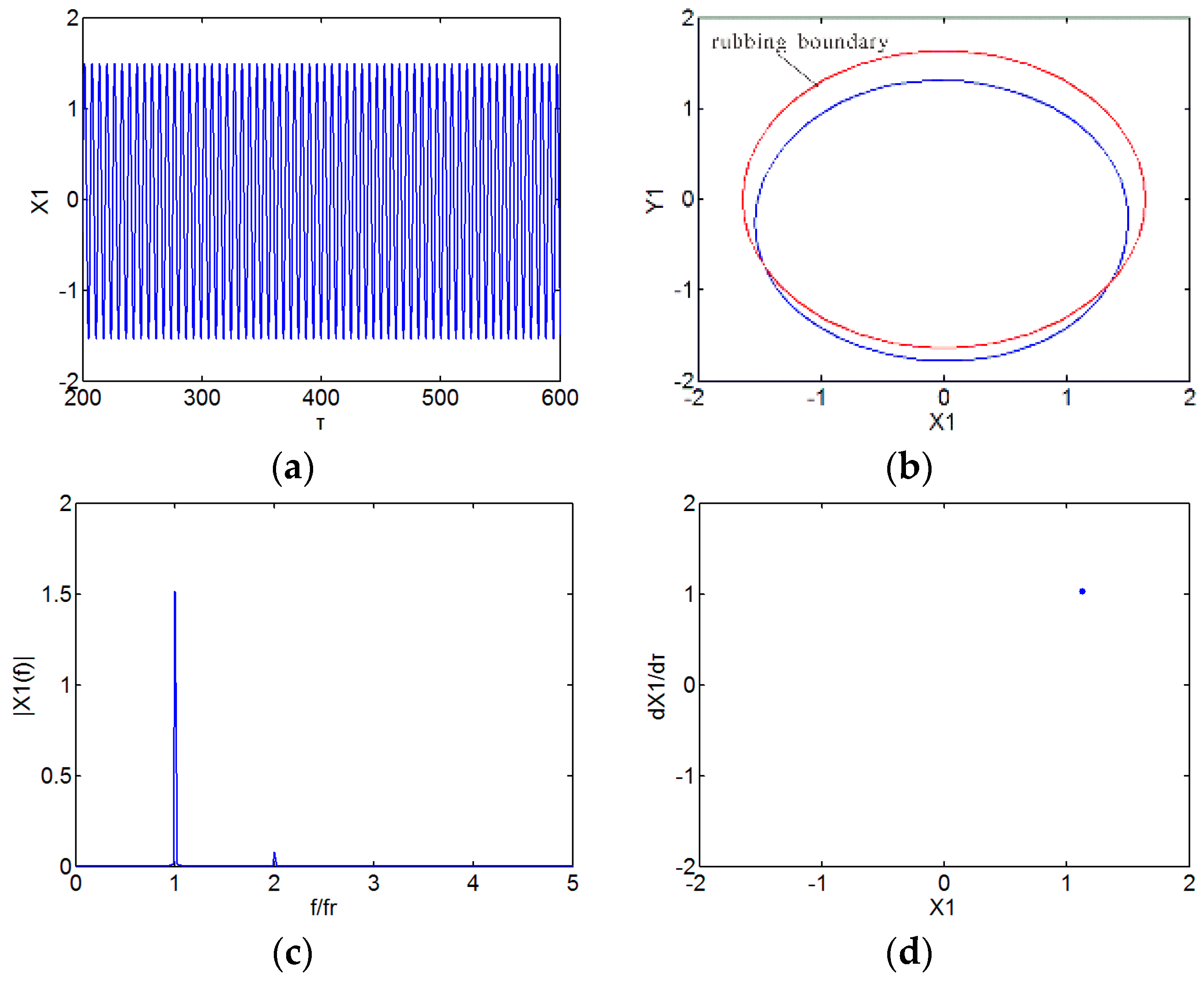
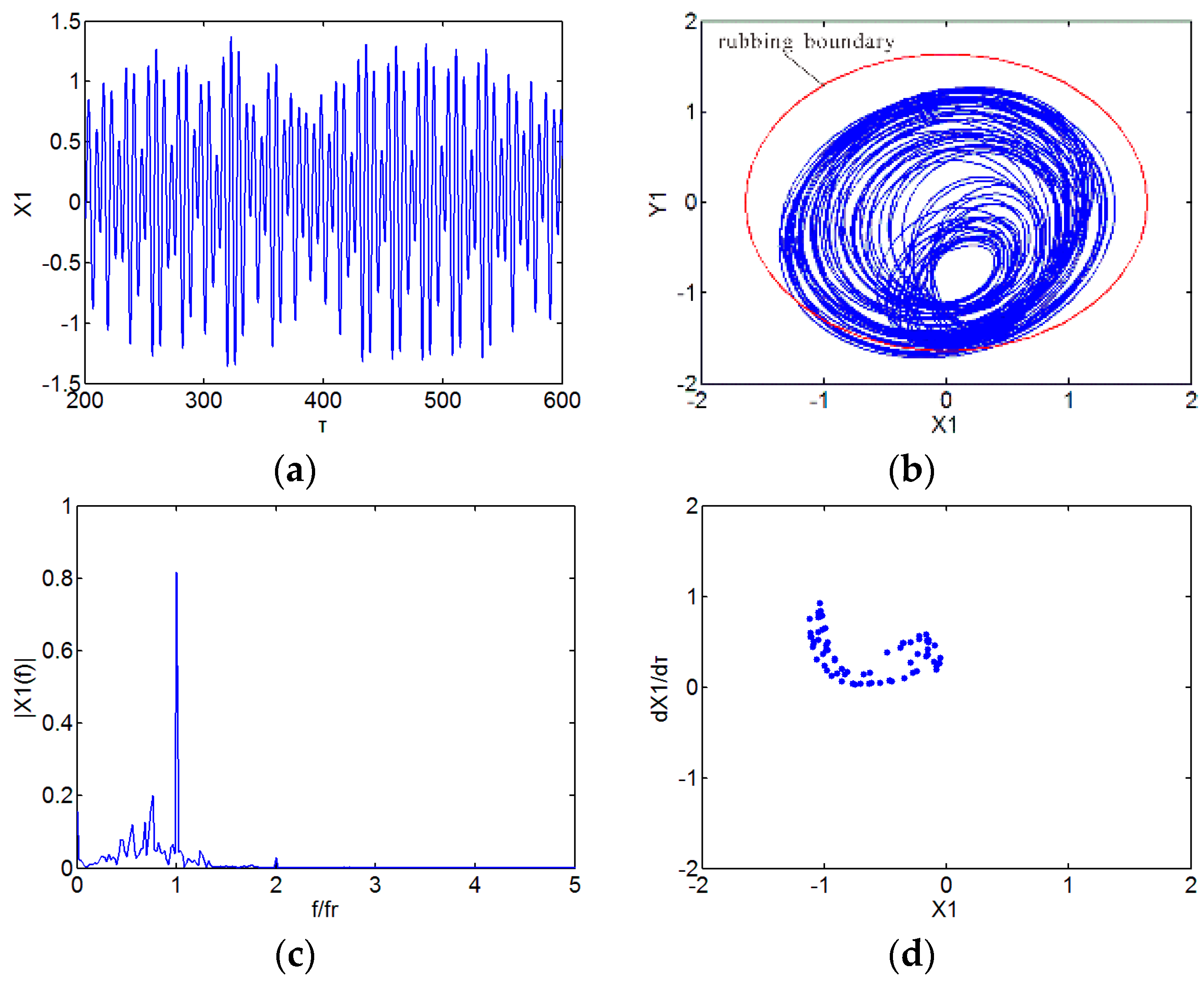
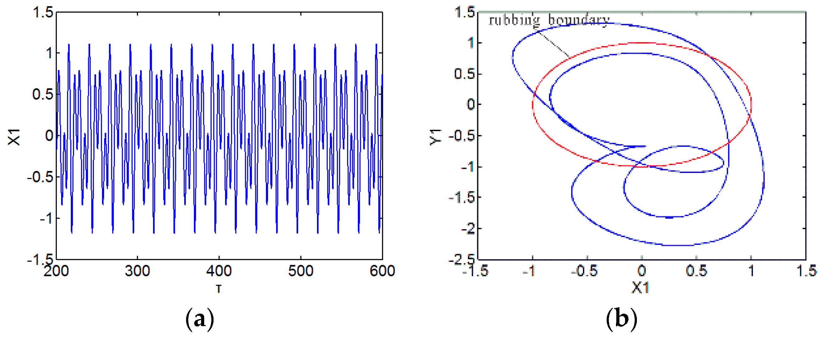
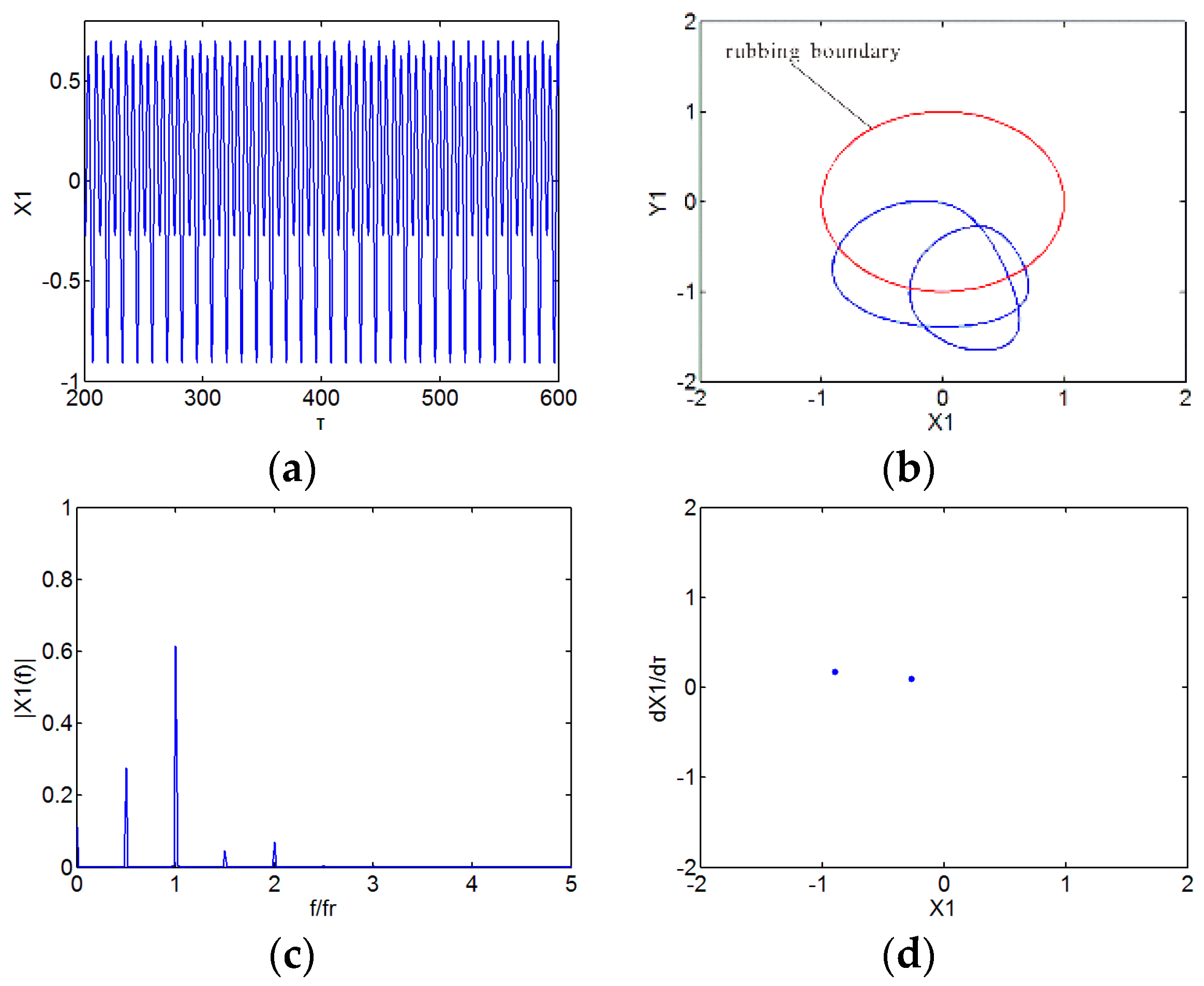
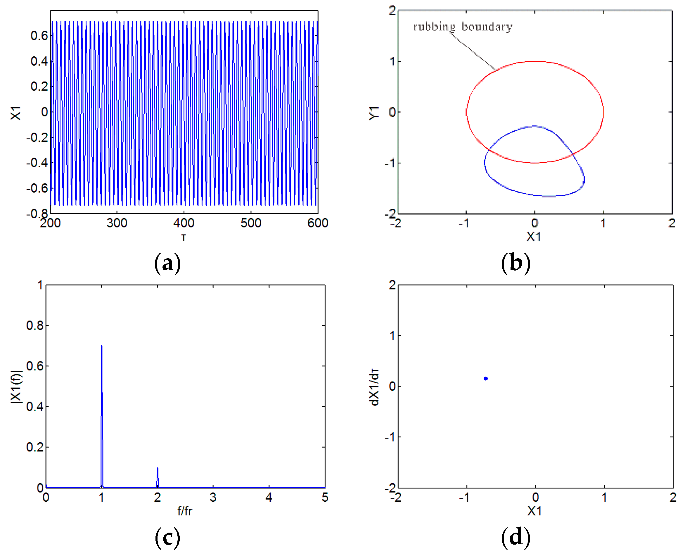
  • The dynamic responses of the rod fastening rotor bearing system under rub-impact and initial permanent deflection exhibit a rich nonlinear dynamic diversity, synchronous periodic-1 motion, multi-periodic motion, chaotic motion and quasi-periodic motion can be observed through the analysis.
  • Initial permanent deflection length has a great effect on the dynamic response of the system in the low-speed regions. With the increase of initial permanent deflection length, the instability speed of the system gradually rises, and the chaotic motion region becomes smaller and smaller.
  • With the increase of radial stiffness of the stator, the system response becomes simpler under certain conditions. Meanwhile, the oil whirl is weaker or even disappears at a certain rotating speed.
  • It is unsuitable to take the rod fastening rotor as an integral rotor in analyzing the coupled nonlinear dynamic responses of the system under rub-impact and initial permanent deflection.
The corresponding results can provide the guidance for the fault diagnosis of a rub-impact rod fastening rotor and contribute to the further understanding of the nonlinear dynamic characteristics of a rub-impact rod fastening rotor.

Acknowledgments

This work is supported by the Research Funds for the Central Universities Achievement Transformation in Beijing (No. ZDZH20141005401), the National Natural Science Foundation of China (No. 51575180) and the Fundamental Research Funds for the Central Universities (No. 2015XS79).

Author Contributions

Liang Hu and Yibing Liu modeled governing motion equations of the rod fastening rotor under rub-impact and initial permanent deflection; Wei Teng designed the Matlab program; Chao Zhou contributed analysis tools; Liang Hu wrote the paper.

Conflicts of Interest

The authors declare no conflict of interest.

Symbols

cRadial clearance of bearing
μOil viscosity
LBearing length
RBearing radius
δSommerfeld correction coefficient
hThickness of oil-film
pDimensionless pressure of oil-film
Fx, FyNonlinear oil-film force in x-direction and y-direction
fx, fyDimensionless nonlinear film force in x-direction and y-direction
PT, PNRub-impact force in radial and tangential direction
Px, PyRub-impact in x-direction and y-direction
ηFriction coefficient
r0Initial clearance
δ0Initial permanent deflection
kcRadial stiffness of the stator
Fcx, FcyRestoring force of contact layer in x-direction and y-direction
mb1, mb2Lumped mass of bearings
m1, m2Lumped mass of disks
e1, e2Eccentric distance of disks
φAngle between mass eccentricity of the two disks
βAngle between mass eccentricity and initial permanent deflection
kShaft stiffness
k1Linear contact stiffness
k1Nonlinear contact stiffness
c1Damping of bearing
c2Damping of disk
c3Damping of contact layer
xi, yi (i = 1, 2)Displacements of disks in x-direction and y-direction
xbi, ybi (i = 1, 2)Displacements of bearings in x-direction and y-direction
Xi, Yi (i = 1, 2)Dimensionless displacements of disks in x-direction and y-direction
Xbi, Ybi (i = 1, 2)Dimensionless displacements of bearings in x-direction and y-direction
ωRotating speed
gGravitational acceleration

References

  1. Muszynska, A. Rotor-to-stationary element rub-related vibration phenomenon in rotating machinery—Literature survey. Shock Vib. Dig. 1989, 21, 3–11. [Google Scholar] [CrossRef]
  2. Ma, H.; Zhao, Q.B.; Zhao, X.Y.; Han, Q.K.; Wen, B.C. Dynamic characteristics analysis of a rotor-stator system under different rubbing forms. Appl. Math. Model. 2015, 39, 2392–2408. [Google Scholar] [CrossRef]
  3. Ma, H.; Yin, F.L.; Wu, Z.Y.; Tai, X.Y.; Wen, B.C. Nonlinear vibration response analysis of a rotor-blade system with blade-tip rubbing. Nonlinear Dyn. 2015, 84, 1225–1258. [Google Scholar] [CrossRef]
  4. Ma, H.; Yu, T.; Han, Q.K.; Zhang, Y.M.; Wen, B.C.; Chen, X.L. Time-frequency features of two types of coupled rub-impact faults in rotor systems. J. Sound Vib. 2009, 321, 1109–1128. [Google Scholar] [CrossRef]
  5. Weaver, B.K.; Zhang, Y.; Clarens, A.F.; Untaroiu, A. Nonlinear Analysis of Rub Impact in a Three-Disk Rotor and Correction Via Bearing and Lubricant Adjustment. J. Eng. Gas Turbines Power 2015, 137, 092504. [Google Scholar] [CrossRef]
  6. Goldman, P.; Muszynska, A. Chaotic behavior of rotor-stator systems with rubs. J. Eng. Gas Turbines Power 1994, 116, 692–701. [Google Scholar] [CrossRef]
  7. Xiang, L.; Hu, A.J.; Hou, L.L.; Xiong, Y.P.; Xing, J.T. Nonlinear coupled dynamics of an asymmetric double-disc rotor-bearing system under rub-impact and oil-film forces. Appl. Math. Model. 2016, 40, 4505–4523. [Google Scholar] [CrossRef]
  8. Wang, C.; Zhang, D.Y.; Ma, Y.H.; Liang, Z.C.; Hong, J. Theoretical and experimental investigation on the sudden unbalance and rub-impact in rotor system caused by blade off. Mech. Syst. Signal Process. 2016, 76, 111–135. [Google Scholar] [CrossRef]
  9. Varney, P.; Green, I. Nonlinear phenomena, bifurcations, and routes to chaos in an asymmetrically supported rotor–stator contact system. J. Sound Vib. 2015, 336, 207–226. [Google Scholar] [CrossRef]
  10. Tai, X.Y.; Ma, H.; Liu, F.H.; Liu, Y.; Wen, B.C. Stability and steady-state response analysis of a single rub-impact rotor system. Arch. Appl. Mech. 2014, 85, 133–148. [Google Scholar] [CrossRef]
  11. Nembhard, A.D.; Sinha, J.K.; Yunusa-Kaltungo, A. Experimental observations in the shaft orbits of relatively flexible machines with different rotor related faults. Measurement 2015, 75, 320–337. [Google Scholar] [CrossRef]
  12. Yunusa-Kaltungo, A.; Nembhard, A.D.; Sinha, J.K. Experimental Observations of Rotor Orbit Analysis in Rotating Machines; Springer: Berlin, Germany, 2015; Volume 21, pp. 1551–1560. [Google Scholar]
  13. Edwards, S.; Lees, A.W.; Friswell, M.I. The influence of torsion on rotor-stator contact in rotating machinery. J. Sound Vib. 1999, 225, 767–778. [Google Scholar] [CrossRef]
  14. Sun, Z.C.; Xu, J.X.; Zhou, T.; Tan, N. Study on influence of bending-torsion coupling in an impacting-rub rotor system. Appl. Math. Mech. 2003, 24, 1316–1323. [Google Scholar]
  15. Khanlo, H.M.; Ghayour, M.; Ziaei-Rad, S. The effects of lateral-torsional coupling on the nonlinear dynamic behavior of a rotating continuous flexible shaft-disk system with rub-impact. Commun. Nonlinear Sci. Numer. Simul. 2013, 18, 1524–1538. [Google Scholar] [CrossRef]
  16. Patel, T.H.; Darpe, A.K. Coupled bending-torsional vibration analysis of rotor with rub and crack. J. Sound Vib. 2009, 326, 740–752. [Google Scholar] [CrossRef]
  17. Yuan, Z.W.; Chu, F.L.; Hao, R.J. Simulation of rotor’s axial rub-impact in full degrees of freedom. Mech. Mach. Theory 2007, 42, 763–775. [Google Scholar] [CrossRef]
  18. Nicholas, J.C.; Gunter, E.J.; Allaire, P.E. Effect of residual shaft bow on unbalance response and balancing of a single mass flexible rotor. J. Eng. Power-Trans. ASME 1976, 98, 171–189. [Google Scholar] [CrossRef]
  19. Song, G.F.; Yang, Z.J.; Ji, C.; Wang, F.P. Theoretical-experimental study on a rotor with a residual shaft bow. Mech. Mach. Theory 2013, 63, 50–58. [Google Scholar] [CrossRef]
  20. Darpe, A.K.; Gupta, K.; Chawla, A. Dynamics of a bowed rotor with a transverse surface crack. J. Sound Vib. 2006, 296, 888–907. [Google Scholar] [CrossRef]
  21. Flack, R.D.; Rooke, J.H. A theoretical-experimental comparison of the synchronous response of a bowed rotor in five different sets of fluid film bearings. J. Sound Vib. 1980, 73, 507–517. [Google Scholar] [CrossRef]
  22. He, P.; Liu, Z.H.; Huang, F.L.; Liu, Z.X. Experimental Study of the Variation of Tie-bolt Fastened Rotor Critical Speeds with Tighten Force. J. Sound Vib. Meas. Diagn. 2014, 34, 644–649. (In Chinese) [Google Scholar]
  23. Yuan, Q.; Gao, J.; Li, P. Nonlinear Dynamics of the Rod-Fastened Jeffcott Rotor. J. Vib. Acoust. 2014, 136, 1–10. [Google Scholar] [CrossRef]
  24. Mat Isa, A.A.; Penny, J.E.T.; Garvey, S.D. Dynamics of bolted and laminated rotors. In Proceedings of the 18th IMAC Conference on Computational Challenges in Structural Dynamics, San Antonio, TX, USA, 7–10 February 2000.
  25. Hei, D.; Lu, Y.J.; Zhang, Y.F.; Liu, F.X.; Zhou, C.; Müller, N. Nonlinear dynamic behaviors of rod fastening rotor-hydrodynamic journal bearing system. Arch. Appl. Mech. 2015, 85, 855–875. [Google Scholar] [CrossRef]
  26. Hei, D.; Lu, Y.J.; Zhang, Y.F.; Lu, Z.Y.; Gupta, P.; Müller, N. Nonlinear dynamic behaviors of a rod fastening rotor supported by fixed–tilting pad journal bearings. Chaos Solitons Fractals 2014, 69, 129–150. [Google Scholar] [CrossRef]
  27. Cheng, L.; Qian, Z.W.; Chen, W.; Fan, J.D. Influence of Structural Parameters on the Bistable Response of a Disk-Rod-Fastening Rotor. J. Sound Vib. Meas. Diagn. 2012, 32, 767–772. (In Chinese) [Google Scholar]
  28. Qian, Z.W.; Cheng, L.; Chen, W.; Li, Y.H. Analysis on bistable response of a disk-rod-fastening rotor. J. Aerosp. Power. 2011, 26, 1563–1568. (In Chinese) [Google Scholar]
  29. Capone, G. Analytical Description of Fluid-dynamic Force Field in Cylindrical Journal Bearing. L'Energia Elettr. 1991, 3, 105–110. [Google Scholar]
  30. Adiletta, G.; Guido, A.R.; Rossi, C. Chaotic Motions of a Rigid Rotor in Short Journal Bearings. Nonlinear Dyn. 1996, 10, 251–269. [Google Scholar] [CrossRef]
Figure 1. Schematic of a rub-impact rod fastening rotor with initial permanent deflection.
Energies 09 00883 g001
Figure 2. Schematic of rub-impact forces.
Energies 09 00883 g002
Figure 3. Schematic of oil-film bearing.
Energies 09 00883 g003
Figure 4. Bifurcation diagram of integral rotor disk center in the x-direction at kc = 1 × 10⁷ N/m, δ0 = 0.
Energies 09 00883 g004
Figure 5. Bifurcation diagram of rod fastening rotor disk 1 center in the x-direction at kc = 1 × 10⁷ N/m, δ0 = 0.
Energies 09 00883 g005
Figure 6. Numerical analysis results at ω = 500 rad/s, δ0 = 0 mm. (a) Time domain waveform; (b) Shaft orbit; (c) Frequency spectrum; (d) Poincaré map.
Energies 09 00883 g006
Figure 7. Numerical analysis results at ω = 670 rad/s, δ0 = 0 mm. (a) Time domain waveform; (b) Shaft orbit; (c) Frequency spectrum; (d) Poincaré map.
Energies 09 00883 g007
Figure 8. Numerical analysis results at ω = 1400 rad/s, δ0 = 0 mm. (a) Time domain waveform; (b) Shaft orbit; (c) Frequency spectrum; (d) Poincaré map.
Energies 09 00883 g008
Figure 9. Numerical analysis results at ω = 1750 rad/s, δ0 = 0 mm. (a) Time domain waveform; (b) Shaft orbit; (c) Frequency spectrum; (d) Poincaré map.
Energies 09 00883 g009
Figure 10. Bifurcation diagram of disk 1 center in a horizontal direction at kc = 1 ×10⁷ N/m, δ0 = 0.01 mm.
Energies 09 00883 g010
Figure 11. Numerical analysis results at ω = 500 rad/s, δ0 = 0.01 mm. (a) Time domain waveform; (b) Shaft orbit; (c) Frequency spectrum; (d) Poincaré map.
Energies 09 00883 g011
Figure 12. Numerical analysis results at ω = 670 rad/s, δ0 = 0.01 mm. (a) Time domain waveform; (b) Shaft orbit; (c) Frequency spectrum; (d) Poincaré map.
Energies 09 00883 g012
Figure 13. Numerical analysis results at ω = 1400 rad/s, δ0 = 0.01 mm. (a) Time domain waveform; (b) Shaft orbit; (c) Frequency spectrum; (d) Poincaré map.
Energies 09 00883 g013
Figure 14. Numerical analysis results at ω = 1750 rad/s, δ0 = 0.01 mm. (a) Time domain waveform; (b) Shaft orbit; (c) Frequency spectrum; (d) Poincaré map.
Energies 09 00883 g014aEnergies 09 00883 g014b
Figure 15. Bifurcation diagram of disk 1 center in a horizontal direction at kc = 1 × 10⁷ N/m. (a) δ0 = 0.01 mm; (b) δ0 = 0.02 mm; (c) δ0 = 0.03 mm; (d) δ0 = 0.04 mm.
Energies 09 00883 g015
Figure 16. Bifurcation diagram of disk 1 center in a horizontal direction.
Energies 09 00883 g016
Figure 17. Numerical analysis results at kc = 1.2 × 10⁷ N/m. (a) Time domain waveform; (b) Shaft orbit; (c) Frequency spectrum; (d) Poincaré map.
Energies 09 00883 g017
Figure 18. Numerical analysis results at kc = 1.9 × 10⁷ N/m. (a) Time domain waveform; (b) Shaft orbit; (c) Frequency spectrum; (d) Poincaré map.
Energies 09 00883 g018aEnergies 09 00883 g018b
Figure 19. Numerical analysis results at kc = 2.85 × 10⁷ N/m. (a) Time domain waveform; (b) Shaft orbit; (c) Frequency spectrum; (d) Poincaré map.
Energies 09 00883 g019
Figure 20. Numerical analysis results at kc = 3.2 × 10⁷ N/m. (a) Time domain waveform; (b) Shaft orbit; (c) Frequency spectrum; (d) Poincaré map.
Energies 09 00883 g020

