Article

A Novel Modulation Function-Based Control of Modular Multilevel Converters for High Voltage Direct Current Transmission Systems

by
Majid Mehrasa
1,†,
Edris Pouresmaeil
2,3,†,
Sasan Zabihi
4,†,
Juan C. Trujillo Caballero
5,† and
João P. S. Catalão
2,3,6,*,†
1
Young Researchers and Elite Club, Sari Branch, Islamic Azad University, Sari 47136, Iran
2
INESC-ID, Instituto Superior Técnico, University of Lisbon, Av. Rovisco Pais, 1, Lisbon 1049-001, Portugal
3
C-MAST, University of Beira Interior, R. Fonte do Lameiro, Covilhã 6201-001, Portugal
4
ABB Australia Pty Limited, Berrimah, Northern Territory 0828, Australia
5
Departamento de Ingeniería Eléctrica, Instituto Tecnológico de Orizaba (ITO), Orizaba, Veracruz 94320, Mexico
6
INESC TEC and Faculty of Engineering of the University of Porto, R. Dr. Roberto Frias, Porto 4200-465, Portugal
*
Author to whom correspondence should be addressed.
The authors contributed equally to this work.
Energies 2016, 9(11), 867; https://doi.org/10.3390/en9110867
Submission received: 22 May 2016 / Revised: 16 October 2016 / Accepted: 17 October 2016 / Published: 25 October 2016
(This article belongs to the Special Issue Advances in Power System Operations and Planning)

Abstract

:
In this paper, a novel modulation function-based method including analyses of the modulation index and phase is proposed for operation of modular multilevel converters (MMCs) in high voltage direct current (HVDC) transmission systems. The proposed modulation function-based control technique is developed based on thorough and precise analyses of all MMC voltages and currents in the a-b-c reference frame in which the alternating current (AC)-side voltage is the first target to be obtained. Using the AC-side voltage, the combination of the MMC upper and lower arm voltages is achieved as the main structure of the proposed modulation function. The main contribution of this paper is to obtain two very simple new modulation functions to control MMC performance in different operating conditions. The features of the modulation function-based control technique are as follows: (1) this control technique is very simple and can be easily achieved in a-b-c reference frame without the need of using Park transformation; and (2) in addition, the inherent properties of the MMC model are considered in the proposed control technique. Considering these properties leads to constructing a control technique that is robust against MMC parameters changes and also is a very good tracking method for the components of MMC input currents. These features lead to improving the operation of MMC significantly, which can act as a rectifier in the HVDC structure. The simulation studies are conducted through MATLAB/SIMULINK software, and the results obtained verify the effectiveness of the proposed modulation function-based control technique.

Graphical Abstract

1. Introduction

Owing to remarkable advantages of multilevel modular converters (MMC) in high-voltage and high-power applications including modular structure, dynamic increment of sub-module (SM) numbers, common direct current (DC)-bus and distributed DC capacitors [1,2,3,4], many pulse width modulation (PWM) techniques have been recently proposed to improve control features of these converters [5,6]. However, although there are many existing control methods, designing new control techniques with more simplicity, more efficiency, faster steady state operation and better transient response with respect to the type of application are always required. In [7], an improved PWM method for half-bridge based MMCs is proposed that is able to generate an output voltage with maximally 2N + 1 levels. The method discussed in this article is as great as a carrier-phase-shifted PWM (CPSPWM) method.
A popular PWM technique, which is the most commonly used method in the Cascaded H-bridge converters (CHB) [8,9], is the phase-shifted carrier (PSC). Because of the following features [10], the PSC modulation is also attractive to MMCs [11,12,13,14]: (1) high modularity and scalability of MMC; (2) easily reaching capacitor voltage balancing control; (3) MMC is able to generate an output voltage with a high switching frequency and a low total harmonic distortion (THD); and (4) MMC structure is able to distribute the semiconductor stress and the power of SMs. For instance, in [10], a mathematical analysis of PSC modulation is presented in order to identify the PWM harmonic characteristics of the MMC output voltage and the circulating current. In addition, the influence of carrier displacement angle between the upper and lower arms on those harmonics is evaluated in this paper. The nearest level modulation (NLM) method, which is also known as the round method, is exhaustively discussed in [15,16,17]. This method is suitable for MMCs particularly with a large number of SMs. In comparison with the conventional NLM, a modified NLM method in which the number of output alternating current (AC) voltage levels is as great as the CPSPWM and the improved SM unified PWM (SUPWM) is proposed for MMCs in [18]. Through this method, the number of AC voltage levels increased to 2N + 1, which is almost double; and the height of the step in the step wave is halved, leading to a better quality for the MMC AC output voltage waveform. By adding a zero-sequence to the original modulation signals, a new discontinuous modulation technique is achieved in [19] along with a circulating current control technique the MMC arms are clamped to the upper or lower terminals of the DC-link bus. In order to minimize the switching losses of the MMC, the clamping intervals can be regulated by the use of the output current absolute value. In [19], a significant reduction in the capacitor voltage ripples with low modulation indices is also obtained. A multilevel selective harmonic elimination pulse-width modulation (MSHE-PWM) technique is schemed in [20] to perform a tight control of the low-order harmonics and the lowest switching frequency for the MMC [21]. Moreover, two different modulation patterns for MSHE-PWM as well as a method for selecting the number of SMs in the phase-legs of the converter are proposed in [21]. According to [22,23], the amplitude modulation is widely employed to control MMC-based high voltage direct current (HVDC) transmission systems. The main idea of the method is to first calculate how many SMs should be put into action, and then the capacitors sorting voltage and the final working sequence should be determined by the direction of the arm current. However, in the case of large numbers of SMs, problems related to frequent sorting of capacitor voltage are issued [24].
A novel modulation function accompanied by its index is figured out in this paper by accurately analyzing all MMC voltages and currents in the a-b-c reference frame in order to improve MMC performance in HVDC applications. Working the AC-side voltage out, a combination of the MMC upper and lower’s arm voltages is achieved. The proposed modulation function that completely depends on MMC parameters and also the specifications of MMC input voltages and currents can be derived by using the AC-side voltage. In order to reach an accurate evaluation of MMC operation under different operational conditions, the impact of parameters and input current variations on the proposed modulation function and its index is investigated that ends up improving MMC control. MATLAB/SIMULINK based simulation results show the effectiveness of the proposed modulation function-based control.

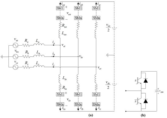
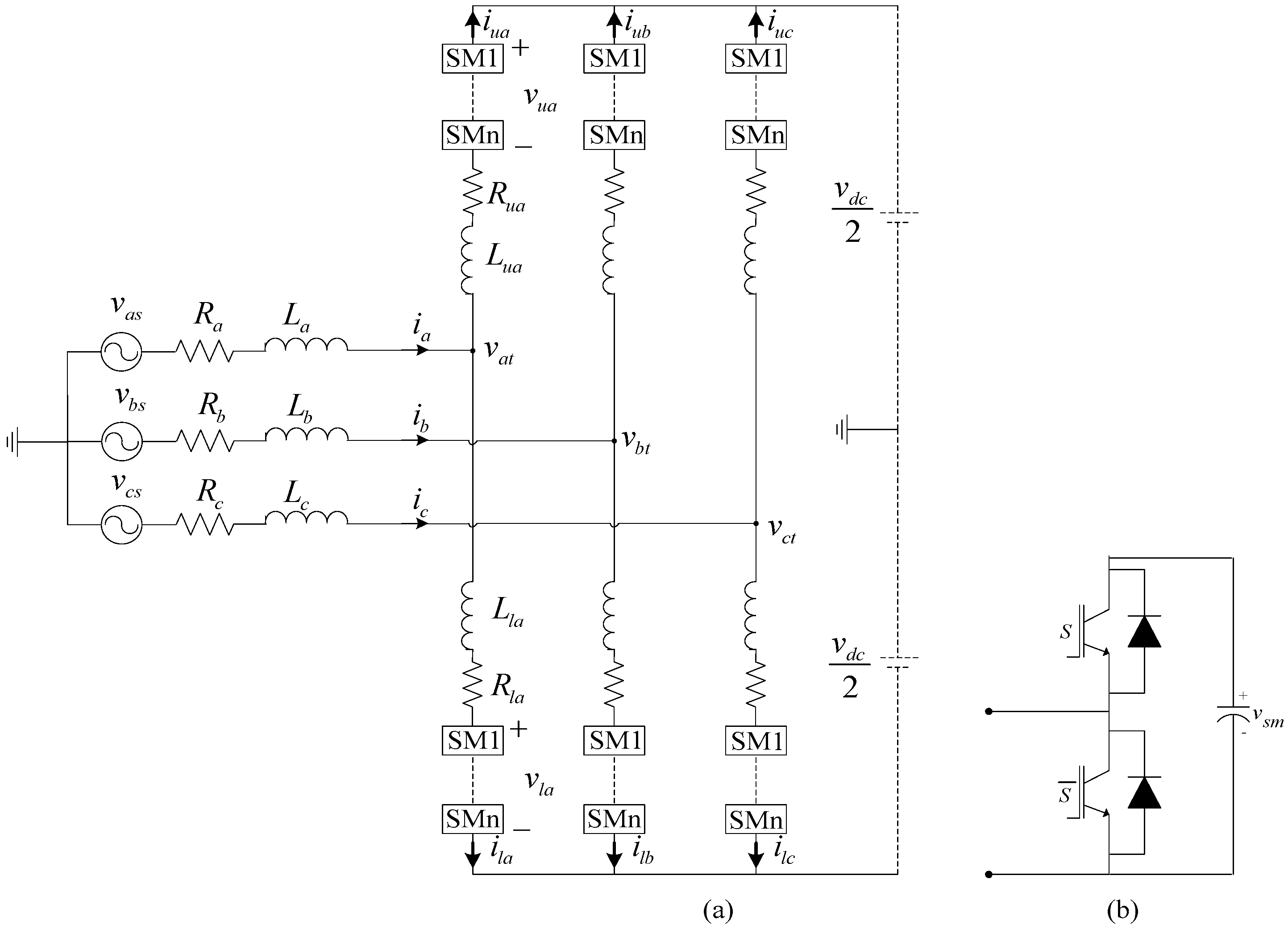
2. Modular Multilevel Converter’s Alternating Current-Side Voltages

The structure of a three-phase MMC is illustrated in Figure 1a. The “2N” numbers of SMs are utilized in each arm, whereas their detailed configuration is depicted in Figure 1b. According to the figure, two complementary insulated-gate bipolar transistor (IGBT)-Diode switches are controlled so that each SM may be placed at either connected or bypassed states based on an appropriate switching method and also required controlling aims. In order to suppress the circulating current and also to restrict the fault current during a DC side fault, an inductor is used in either sides of each arm. The series resistor of each arm represents the combination of the arm losses and the inner inductor resistance.

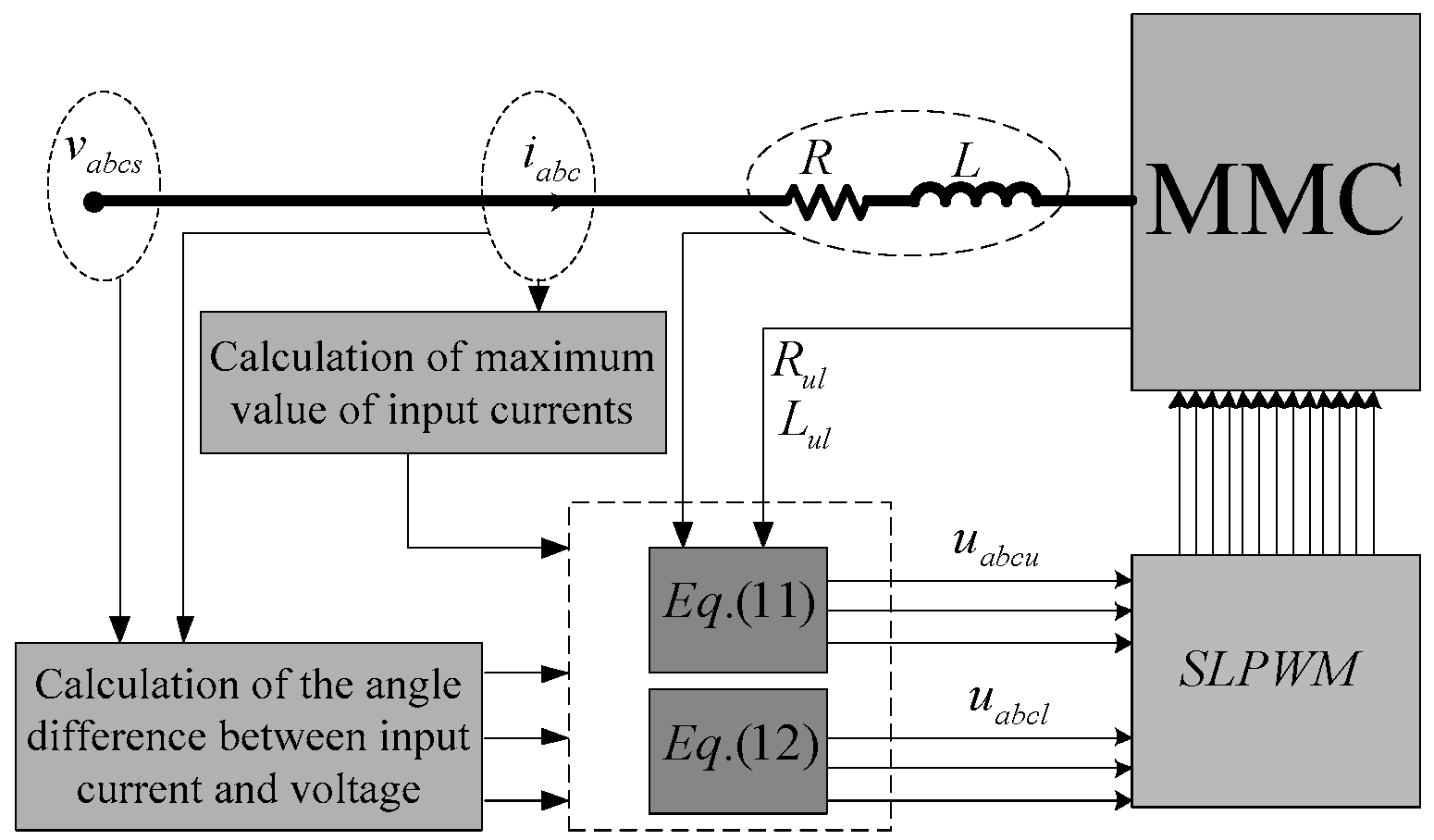
Detailed Calculation of the Alternating Current-Side Voltage

The operation of the used SMs in MMC is highly dependent on the AC-side voltages. As can be inferred from Figure 1a, the AC-side voltages are directly related to the input variables and parameters. Suppose that MMC input voltage and current of phase “a” are:
v a s = v m cos ( ω t ) , i a = I m a cos ( ω t + α a )
Based on the proposed MMC structure shown in Figure 1a, the relationship between the input and the AC-side voltages of phase “a” can be written as:
v a s v a t = L a d i a d t + R a i a
By substituting Equation (1) into Equation (2), the AC-side voltage of phase “a” can be achieved as Equation (3):
v a t = L a 2 I m a 2 ω 2 + R a 2 I m a 2 + v m 2 + 2 v m L a I m a ω sin ( α a ) 2 v m R a I m a cos ( α a ) × cos ( ω t + t a g 1 ( [ v m + L a I m a ω sin ( α a ) R a I m a cos ( α a ) ] [ L a I m a ω cos ( α a ) + R a I m a sin ( α a ) ] ) π / 2 )
To present more explanations, Equation (3) can be rewritten as Equation (4):
v k t = L k 2 I m k 2 ω 2 + R k 2 I m k 2 + v m 2 + 2 v m L k I m k ω sin ( α k ) 2 v m R k I m k cos ( α k ) × cos ( ω t + t a g 1 ( [ v m + L k I m k ω sin ( α k ) R k I m k cos ( α k ) ] [ L k I m k ω cos ( α k ) + R k I m k sin ( α k ) ] ) + 2 π j 3 π 2 )
where j is equal to 0, −1 and 1 for the phases of “a”, “b” and “c”, respectively. The indices of k are the phases sign of “a”, “b” and “c”. Equation (4) shows the general three phase AC-side voltages. As can be realized from Equation (4), the AC-side voltages of MMC can be completely affected by input parameters and variables.

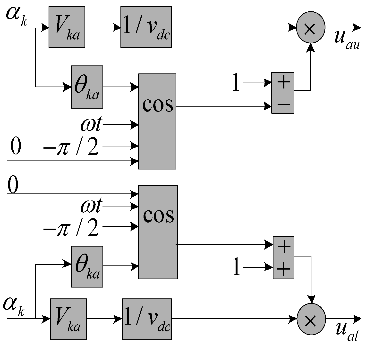
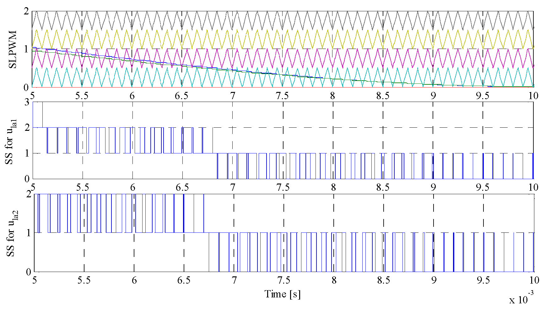
3. Analysis of Proposed Modulation Function

The proposed modulation function is obtained in this section involving AC-side voltages. The voltages placed in entire upper and lower SMs can be aimed to generate signals required for SM switches. Thus, applying Kirchhoff’s voltage law’s (KVL’s) on phase “a” arms of the MMC, the following equations are derived as:
v a t v d c / 2 = L a u d i a u d t + R a u i a u v a u
v a t + v d c / 2 = L a l d i a l d t + R a l i a l + v a l
By summing up two sides of the equations in Equations (5) and (6) and also assuming L a u = L a l = L a t , the following equation is attained:
v a l v a u = 2 v a t L a t d i a d t R a t i a
By substitution of Equations (1) and (3) into Equation (7), Equation (8) can be achieved as:
v a l v a u = ( 2 L a + L a t ) 2 I m a 2 ω 2 + ( 2 R a + R a t ) 2 I m a 2 + 4 v m 2 + 4 v m ( 2 L a + L a t ) I m a ω sin ( α a ) 4 v m ( 2 R a + R a t ) I m a cos ( α a ) cos ( ω t + t a g 1 ( [ 2 v m + ( 2 L a + L a t ) I m a ω sin ( α a ) ( 2 R a + R a t ) I m a cos ( α a ) ] [ ( 2 L a + L a t ) I m a ω cos ( α a ) + ( 2 R a + R a t ) I m a sin ( α a ) ] ) π 2 )
As been discussed in former section, Equation (8) can be rewritten in a general form as Equation (9):
v k l v k u = ( 2 L k + L k t ) 2 I m k 2 ω 2 + ( 2 R k + R k t ) 2 I m k 2 + 4 v m 2 + 4 v m ( 2 L k + L k t ) I m k ω sin ( α k ) 4 v m ( 2 R k + R k t ) I m k cos ( α k ) × cos ( ω t + 2 π j 3 π 2 + t a g 1 ( [ 2 v m + ( 2 L k + L k t ) I m k ω sin ( α k ) ( 2 R k + R k t ) I m k cos ( α k ) ] [ ( 2 L k + L k t ) I m k ω cos ( α k ) + ( 2 R k + R k t ) I m k sin ( α k ) ] ) )
The term “ v k l v k u ” is used to acquire reference waveforms for shift level pulse width modulation (SLPWM). As evident in Equation (10), the reference signals of the proposed PWM can be changed by input and arm parameters of MMC as well as input voltages and currents characteristics. Considering the reference values of I m k * , v m * and α k * as input currents and voltages, the proposed modulation index can be written as:
m k = V k t ( L k , R k , L k t , R k t , I m k * , v m * , α k * ) v d c = 1 v d c ( 2 L k + L k t ) 2 I m k * 2 ω 2 + ( 2 R k + R k t ) 2 I m k * 2 + 4 v m * 2 + 4 v m * ( 2 L k + L k t ) I m k * ω sin ( α k * ) 4 v m * ( 2 R k + R k t ) I m k * cos ( α k * )
Based on Equations (9) and (10), and also assuming the reference values of input variables, the proposed modulation functions can be achieved as:
u k u = m k ( 1 cos ( ω t + 2 π j 3 π 2 + t a g 1 ( [ 2 v m + ( 2 L k + L k t ) I m k ω sin ( α k ) ( 2 R k + R k t ) I m k cos ( α k ) ] [ ( 2 L k + L k t ) I m k ω cos ( α k ) + ( 2 R k + R k t ) I m k sin ( α k ) ] ) ) )
u k l = m k ( 1 + cos ( ω t + 2 π j 3 π 2 + t a g 1 ( [ 2 v m + ( 2 L k + L k t ) I m k ω sin ( α k ) ( 2 R k + R k t ) I m k cos ( α k ) ] [ ( 2 L k + L k t ) I m k ω cos ( α k ) + ( 2 R k + R k t ) I m k sin ( α k ) ] ) ) )
The proposed modulation functions configurations for phase “a” are drawn in Figure 2. With respect to Equations (11) and (12), the proposed index and function are plotted in Figure 3 for I m k * = 50 A and α k * = 0 . As evident in Figure 3, the index modulation is quite close to unity. The effects of MMC parameters and input currents on the proposed modulation functions are comprehensively investigated in the next section. The parameters of V a t and θ a t are given in Appendix.

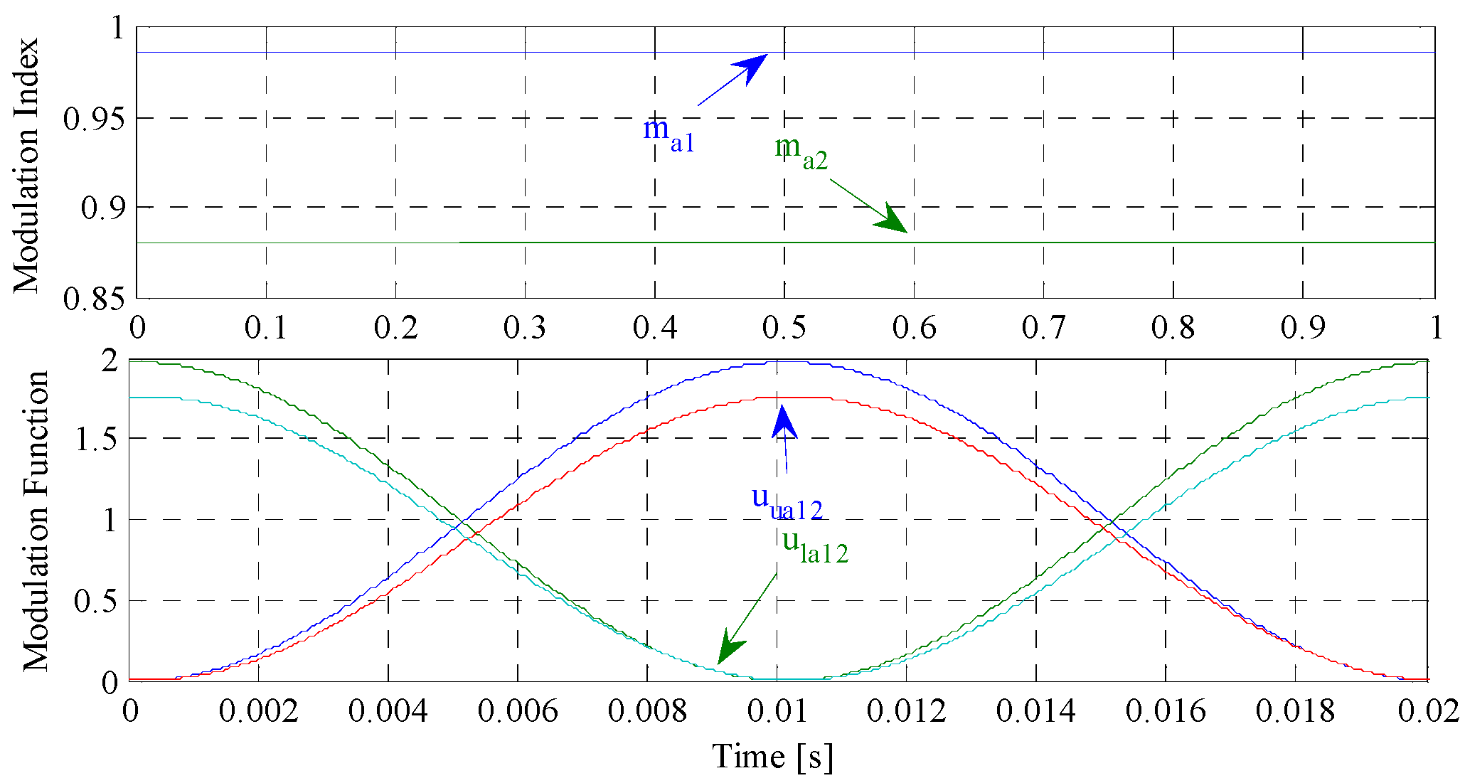
3.1. Parameters Variation Effects on the Proposed Modulation Function

In this section, system parameters are changed to the ones given in Table 2 in order to evaluate the effects of the parameters variations on the proposed modulation function. The base parameters are as given in Table 1. By increasing the system parameters, the proposed modulation indexes are decreased as depicted in Figure 4. The variation trend of the proposed modulation function is also illustrated in Figure 4. According to this figure, in addition to the index changes, the phase angles of both upper and lower modulation functions in three conditions slightly tend to be shifted. For the two obtained modulation functions, a typical shifted-level PWM in intervals of 5 ms t 10 ms is shown in Figure 5. Figure 5 demonstrates that the switching numbers of the second and third levels are decreased, and, instead, the numbers of the lowest level switching is increased. The scenario is inversed for the proposed lower modulation function but not with a similar change in the numbers. As depicted in Figure 6, the presented SLPWM results in a raise in the switching numbers of the second and the third levels and a drop in the switching numbers of the first levels. The sum of the switching generations in both proposed upper and lower modulation functions should lead to a constant value in each level.

3.2. Input Current Variation Effects on the Proposed Modulation Function

The magnitude and phase angle of the input currents impact on the proposed modulation function that is reviewed in this section. The specifications of the input current are changed to Imk = 100 A and α k = π / 6 at t = 0.2 s. In comparison with parameter variations, the MMC input current variations can make more reduction in the modulation index and phase angle of the proposed modulation functions as illustrated in Figure 7. The effects of the input current changes on the applied SLPWM are shown in Figure 8 and Figure 9. The proposed upper modulation function with its shifted-level triangle waveforms as well as the respective generated signals for two different input currents are drawn in Figure 8. It can be seen that the number of switching signals (SS) in the second level is significantly increased for the MMC operating in the second condition compared with the first one. On the other hand, the first and the second levels of SS are slightly increased for SLPWM applied to the proposed lower modulation function as shown in Figure 9. Considering the interval of 5 ms t 10 ms as a sampling period, the input current changes impact more on the operation of the proposed upper modulation function.

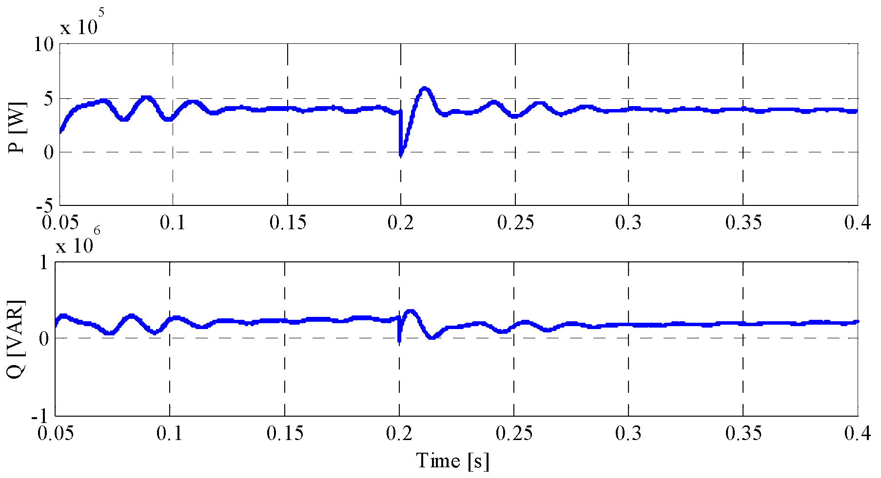
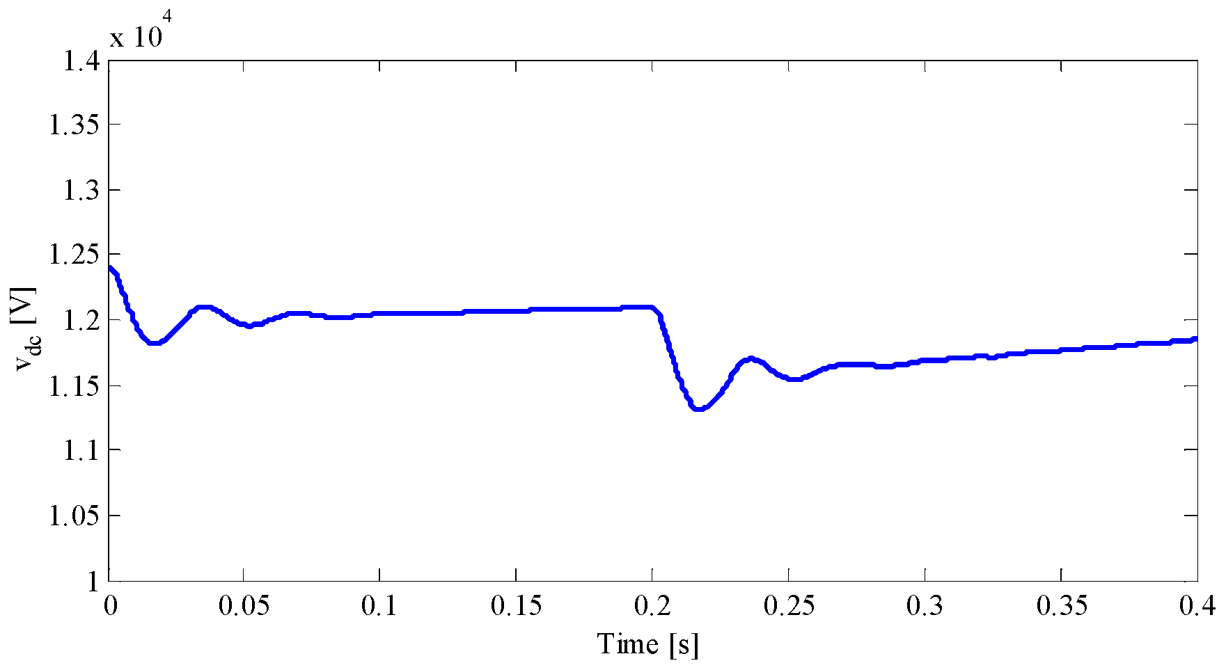
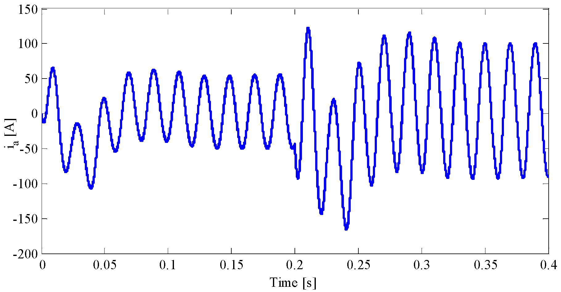
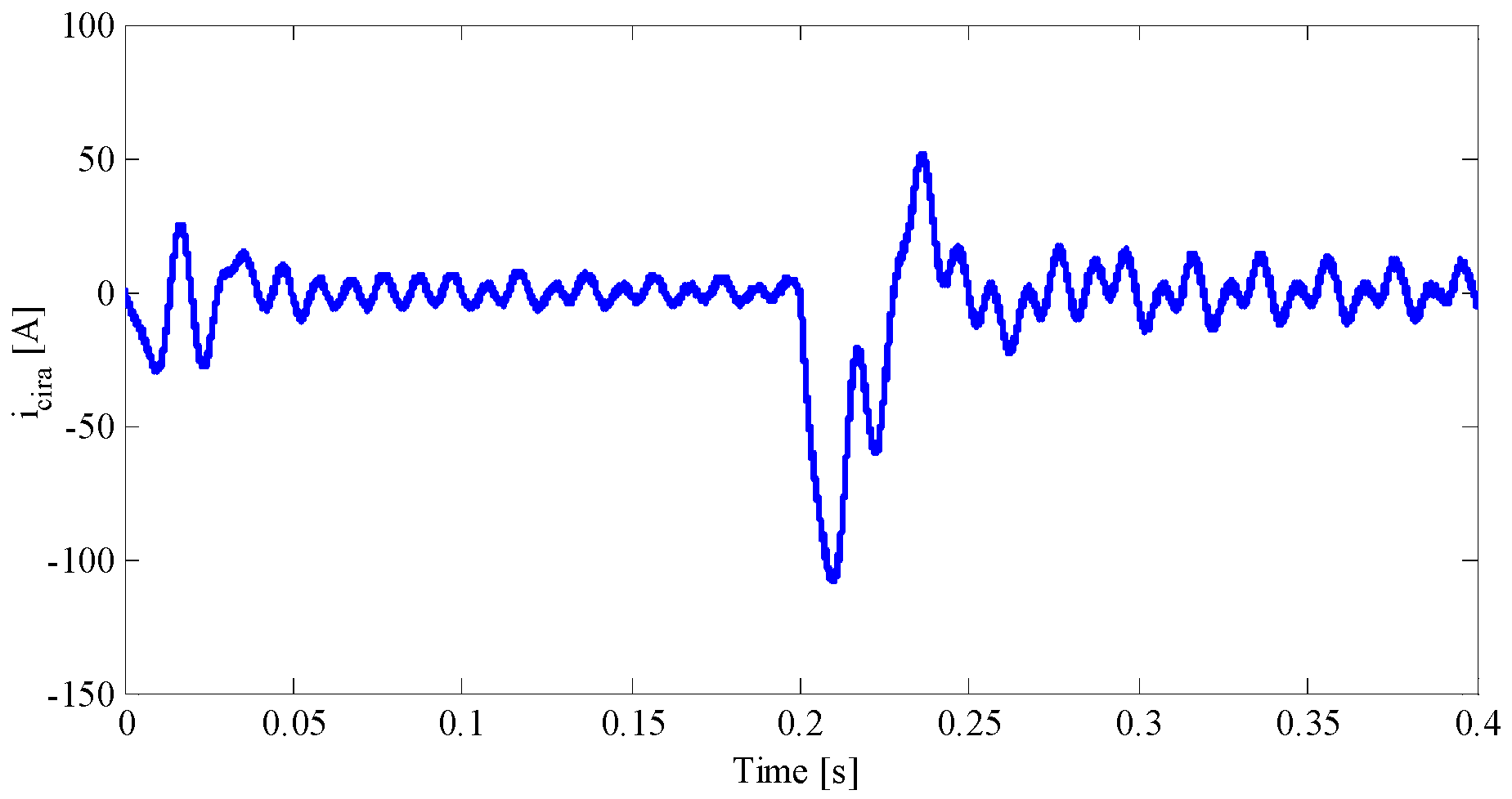
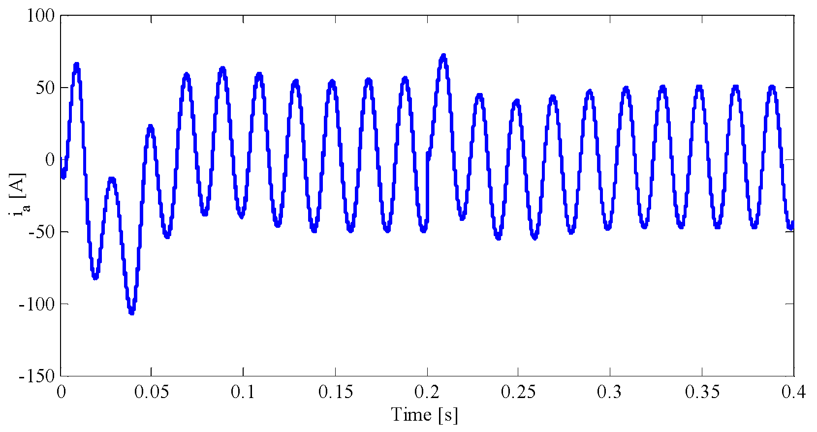
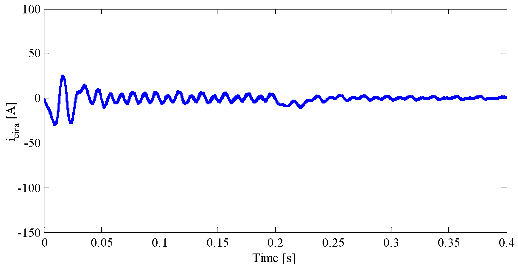
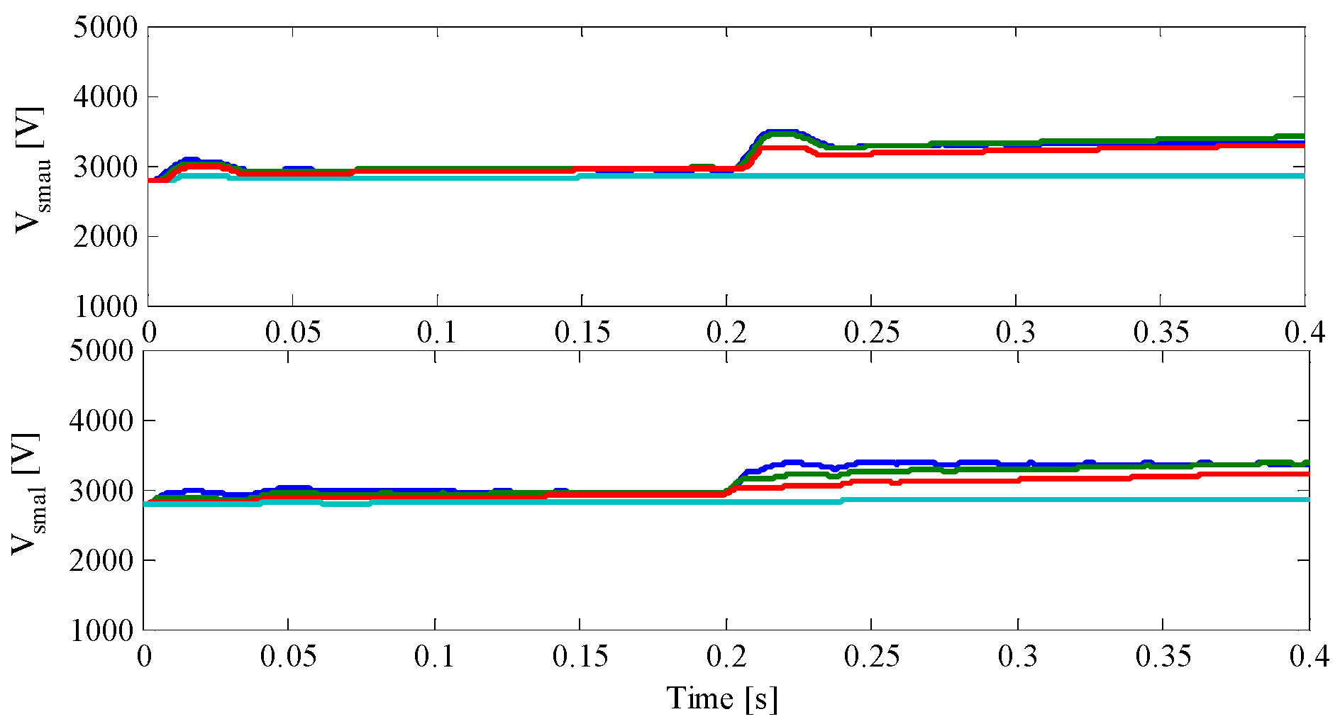
4. Simulation Results

In this section, the control of MMC is executed by the use of proposed modulation function as given in Figure 10. MATLAB/SIMULINK environment in discrete mode is used to perform the overall control structure modelling based on the information given in Table 1 and Table 2. Throughout the evaluation process of MMC operation as a rectifier in HVDC application, the simulation sampling time is selected at the value of one micro second. In addition, initial value of 3 kV is considered for all SM capacitors.

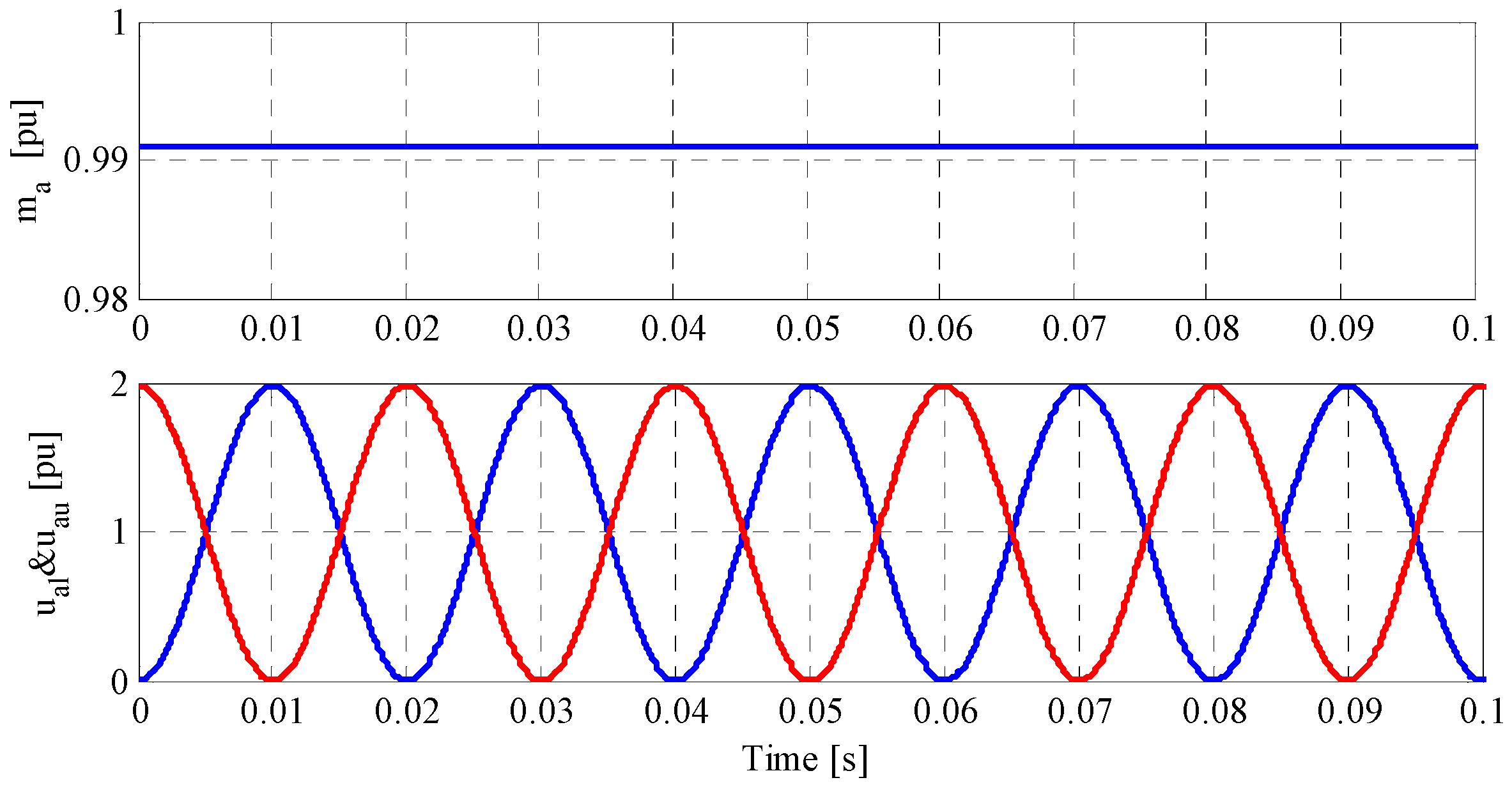
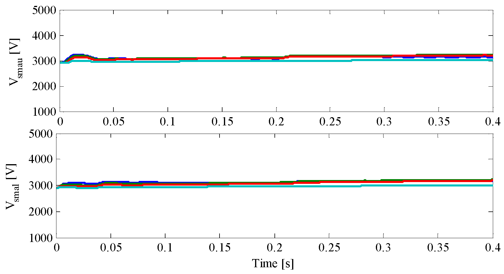
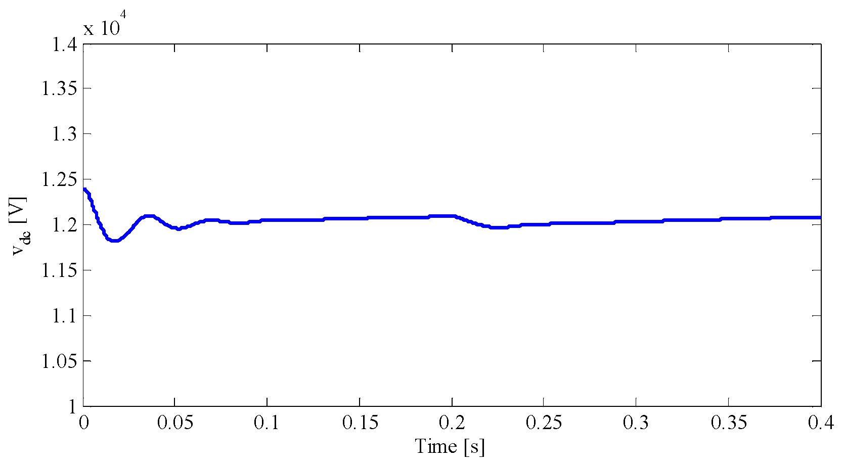
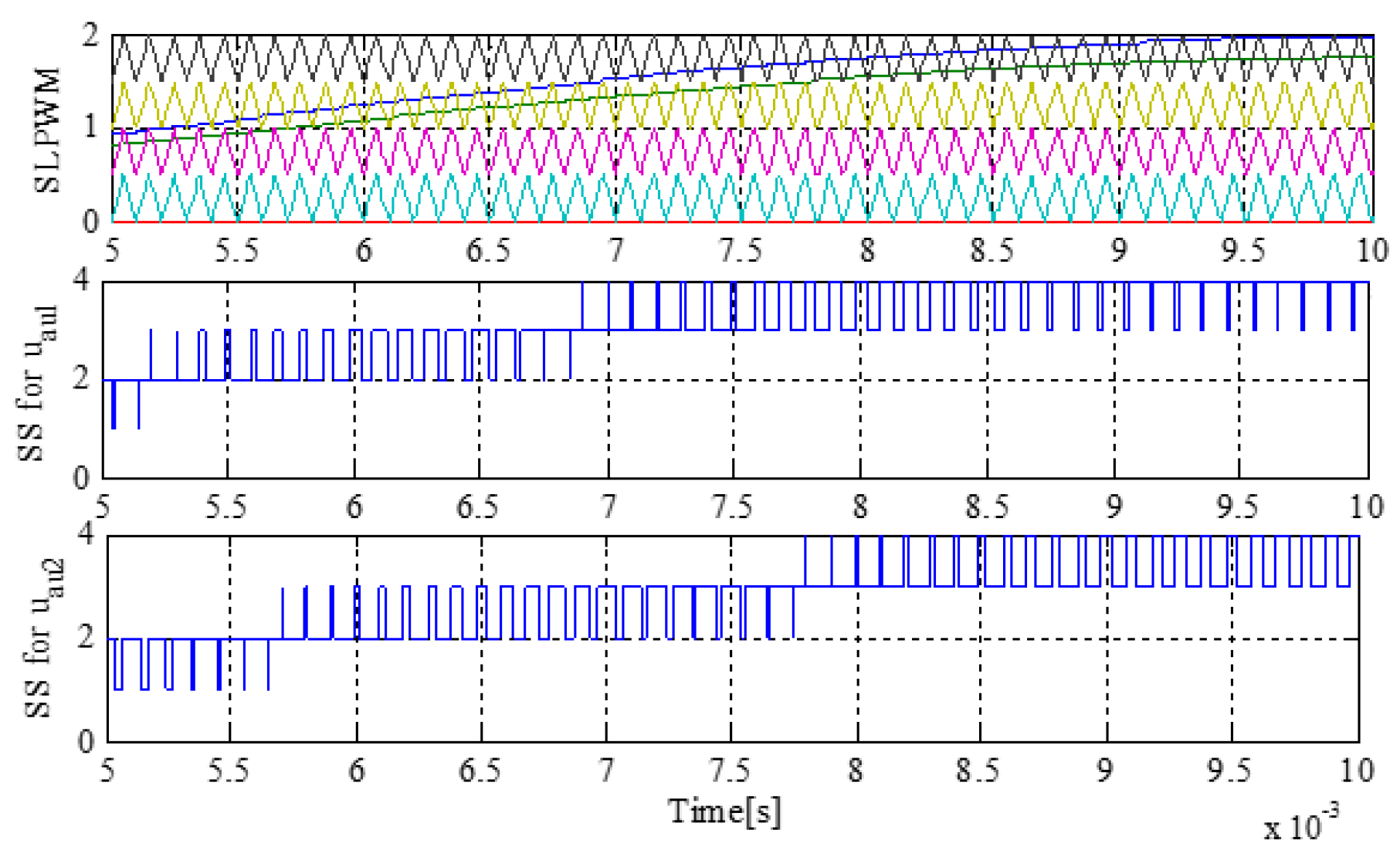
4.1. Parameter Variation Evaluation

The obtained functions in Equations (11) and (12) are considered as carrier waveforms in SLPWM in these simulations. As can be observed, both amplitude and phase angle of the proposed modulation functions can be controlled by varying MMC arm and input parameter changes. In the first section of simulation that is (0, 0.2) seconds, MMC operates in a steady state with parameters given in Table 1. Then, at t = 0.2 s, the MMC parameters are changed to the values given in Table 2. As can be seen in Figure 11, voltages of SMs in phase “a” are kept at their desired values of 3 kV with initial parameters. After parameter variations, the proposed modulation function-based controller is able to acceptably regulate SM voltages, except for a slight deviation from the desired value at t = 0.2 s. Figure 12 shows the DC-link voltage of the MMC. Initially, MMC can reach targeted DC-link voltage after a short transient response. With a very small undershoot, the modulation algorithm continues to attain MMC’s desired DC-link voltage after parameter alterations. Phase “a” current of MMC is illustrated in Figure 13. According to this figure, MMC can generate the assumed current with the amplitude of 50 for both sets of parameters; however, there are negligible transient responses. The active and reactive power sharing of MMC with parameter changes are illustrated in Figure 14. As it can be seen in this figure, the MMC active and reactive powers follow the desired values, even after MMC parameter changes, along with their proportional alterations. The appropriate operation of a designed controller for MMC must lead to minimization of circulating currents. The proposed controller is capable of achieving minimized circulating currents of MMC as depicted in Figure 15. As shown in this figure, the circulating current of phase “a” remains at an acceptable level in both operation states.

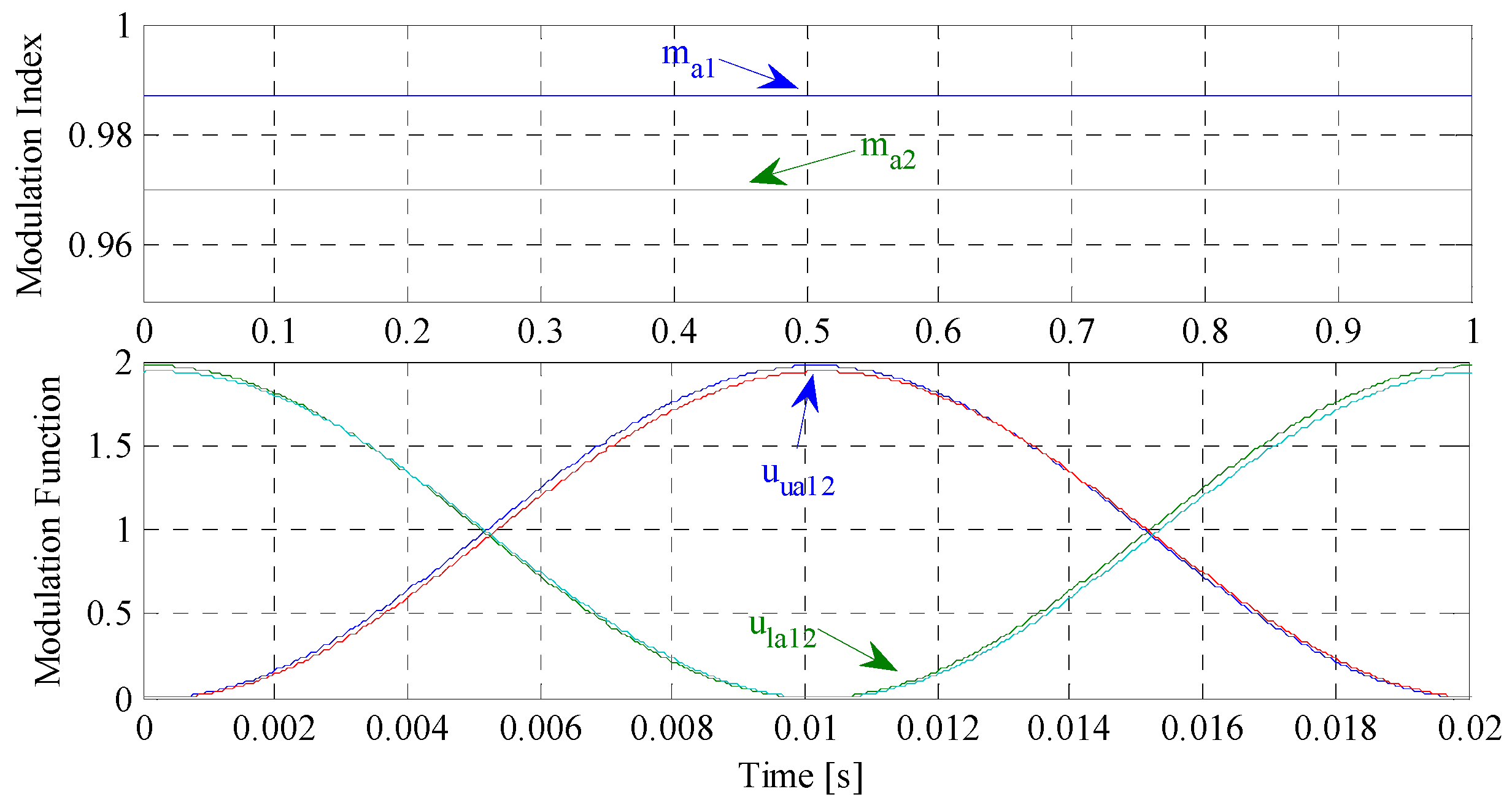
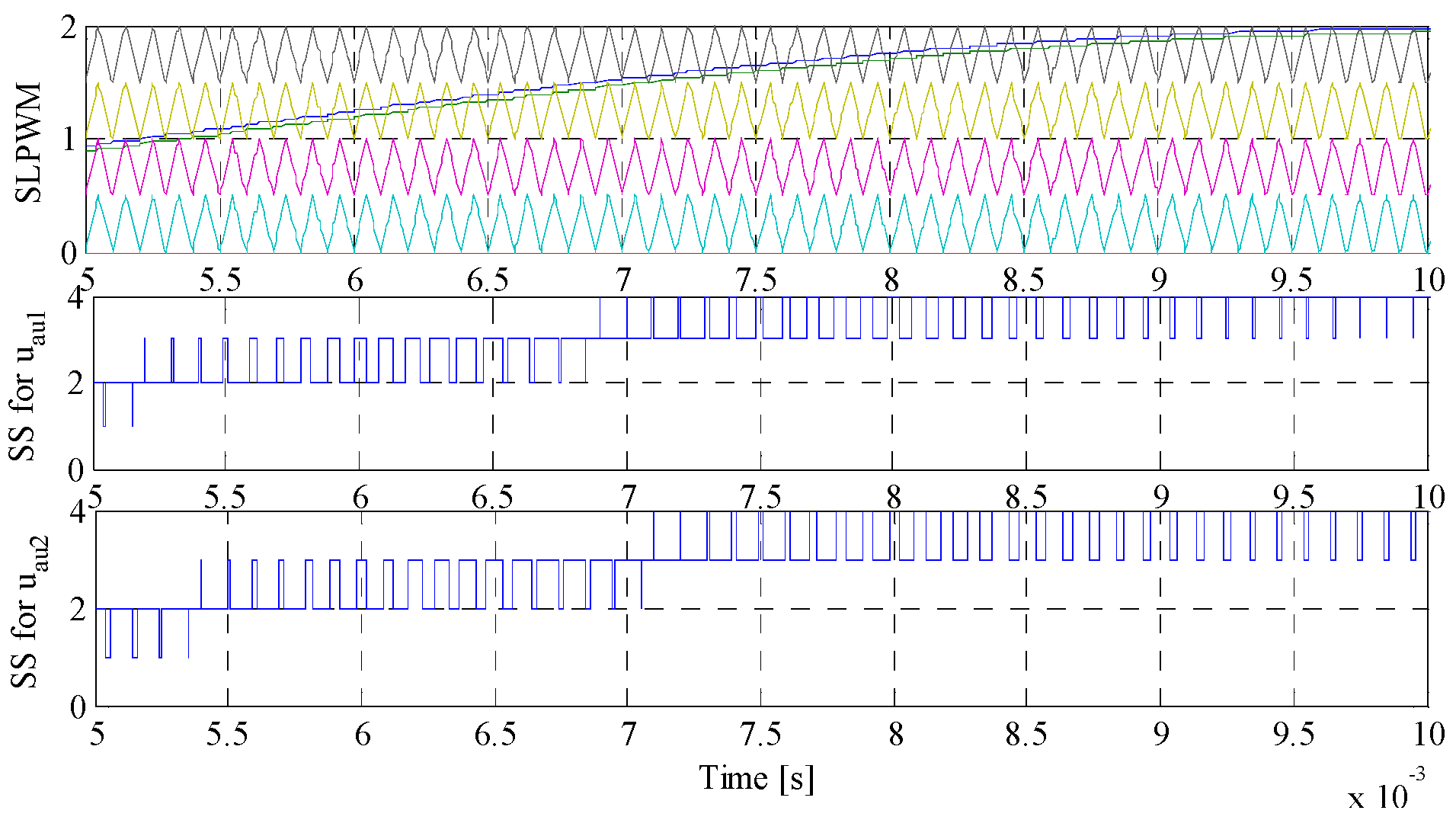
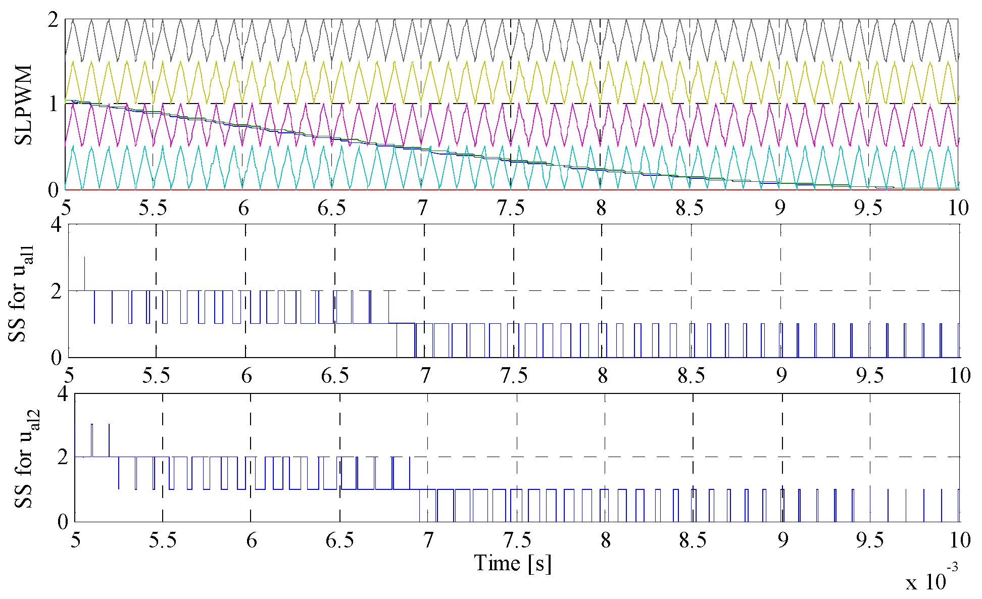
4.2. Evaluation of Modular Multilevel Converter Input Current Variation

Changing the input current components of α k and I m k creates different modulation functions for the proposed modulation function-based controller. Thus, the changes caused by input MMC currents should lead to properly commanding the proposed controller to keep MMC in stable operation. In the primary interval, MMC operates with α k = 0 , Imk = 50 A and the parameters given in Table 1. Then, the input MMC currents reach a magnitude of Imk = 100 A with the phase angle of α k = π / 6 at t = 0.2 s, though keeping the same parameters. The MMC SM voltages of both operation states are demonstrated in Figure 16. As can be understood from Figure 16, the voltages follow the reference value with a slight transient response and also acceptable steady-state error. Moreover, the DC-link voltage of MMC experiences an undershoot after the current variation at t = 0.2 s as depicted in Figure 17. After the transition, the proposed controller shows its dynamic capability in keeping the MMC DC-link voltage with an acceptable deviation from the desired value. Figure 18 contains the MMC input current of phase “a”. Based on this figure, the MMC input current is changed matching the current magnitude to the command, even though with a short period of transient response. Figure 19 shows the active and reactive power of MMC with MMC input current changes. According to this figure, both active and reactive powers of MMC are accurately changed based on the governed MMC input current. The circulating current of MMC is also shown in Figure 20. The curve in this figure implies that minimizing circulating current can be effectively accomplished after variation of the input current.

5. Conclusions

In order to effectively control the operation of MMC in HVDC transmission systems, a novel modulation function with a specified index was proposed in this paper. For this purpose, analysing all MMC voltages and currents in a-b-c reference frames was performed to primarily obtain the AC-side voltage. Then, the combination of the MMC upper and lower arm voltages was achieved by the use of already obtained AC-side voltage. Using this combination led to deriving the proposed modulation function and its modulation index, both depending on MMC parameters, and also the specifications of MMC input voltages and currents. In order to improve the performance of the proposed controller, the impacts of parameters and input current variations on the proposed modulation function and its index were thoroughly investigated in a range of operating points. The main feature of the proposed control technique is its very simple design in a-b-c reference frame, being additionally able to provide a robust performance against MMC parameter changes. MATLAB/SIMULINK allowed verification of the effectiveness of the proposed modulation function-based control technique.

Acknowledgments

This work was supported by FEDER funds through COMPETE 2020 and by Portuguese funds through FCT, under Projects FCOMP-01-0124-FEDER-020282 (Reference PTDC/EEA-EEL/118519/2010), POCI-01-0145-FEDER-016434, POCI-01-0145-FEDER-006961, UID/EEA/50014/2013, UID/CEC/50021/2013, and UID/EMS/00151/2013. In addition, the research leading to these results has received funding from the EU Seventh Framework Programme FP7/2007-2013 under grant agreement No. 309048.

Author Contributions

All authors have worked on this manuscript together and all authors have read and approved the final manuscript.

Conflicts of Interest

The authors declare no conflict of interest.

Nomenclature

Abbreviation
MMCModular multilevel converter
HVDCHigh voltage direct current
SLPWMShift level pulse width modulation
SSSwitching signals
SMSub-module
ACAlternating current
KVLKirchhoff’s voltage law
Variables
ikInput MMC currents
ImkMagnitude of input MMC currents
ikuUpper arm currents
iklLower arm currents
I m k * Reference values of input MMC currents
vksInput MMC voltages
vklAC-side voltages
vmMagnitude of input MMC voltages
v m * Reference value of input MMC voltage
vkuUpper arm voltages
vklLower arm voltages
vDCMMC DC-link voltage
ukuSwitching function for Upper’s arms
uklSwitching function for Lower’s arms
mkProposed modulation index
αkAngle between input MMC voltages and currents
α k * Reference value of α k
VktMagnitude of upper and lower voltage difference
θktAngle of upper and lower voltage difference
Parameters
LkInput inductance of MMC
RkInput resistance of MMC
LkulArm’s inductance of MMC
RkulArm’s resistance of MMC
LktEquivalent arm’s inductance of MMC
RktEquivalent arm’s resistance of MMC
ωAngular frequency of MMC

Appendix

This part is mainly for Figure 2.
V a t = ( 2 L a + L a t ) 2 I m a 2 ω 2 + ( 2 R a + R a t ) 2 I m a 2 + 4 v m 2 + 4 v m ( 2 L a + L a t ) I m a ω sin ( α a ) 4 v m ( 2 R a + R a t ) I m a cos ( α a ) θ a t = t a g 1 ( [ 2 v m + ( 2 L a + L a t ) I m a ω sin ( α a ) ( 2 R a + R a t ) I m a cos ( α a ) ] [ ( 2 L a + L a t ) I m a ω cos ( α a ) + ( 2 R a + R a t ) I m a sin ( α a ) ] )

References

  1. Marquardt, R. Modular multilevel converter: An universal concept for HVDC-Networks and extended DC-Bus applications. In Proceedings of the 2010 International Conference on Power Electronics (IPEC2010), Tokyo, Japan, 21–24 June 2010; pp. 502–507.
  2. Glinka, M.; Marquardt, R. A new AC/AC multilevel converter family. IEEE Trans. Ind. Electron. 2005, 52, 662–669. [Google Scholar] [CrossRef]
  3. Pouresmaeil, E.; Mehrasa, M.; Shokridehaki, M.A.; Rodrigues, E.; Catalao, J.P.S. Control of multi modular converters for integration of distributed generation sources into the power grid. In Proceedings of the IEEE International Conference on Smart Energy Grid Engineering (SEGE) 2015, Oshawa, ON, Canada, 17–19 August 2015.
  4. Gnanarathna, U.N.; Gole, A.M.; Jayasinghe, R.P. Efficient modeling of modular multilevel HVDC converters (MMC) on electromagnetic transient simulation programs. IEEE Trans. Power Deliv. 2011, 26, 316–324. [Google Scholar] [CrossRef]
  5. Tu, Q.; Xu, Z.; Xu, L. Reduced-switching frequency modulation and circulating current suppression for modular multilevel converters. IEEE Tran. Power Deliv. 2011, 26, 2009–2017. [Google Scholar]
  6. Mei, J.; Xiao, B.; Shen, K.; Tolbert, L.M.; Zheng, J.Y. Modular multilevel inverter with new modulation method and its application to photovoltaic grid-connected generator. IEEE Trans. Power Electron. 2013, 28, 5063–5073. [Google Scholar] [CrossRef]
  7. Li, Z.; Wang, P.; Zhu, H.; Chu, Z.; Li, Y. An improved pulse width modulation method for chopper-cell-based modular multilevel converters. IEEE Trans Power Electron. 2012, 27, 3472–3481. [Google Scholar] [CrossRef]
  8. Kouro, S.; Malinowski, M.; Gopakumar, K.; Pou, J.; Franquelo, L.G.; Wu, B.; Rodriguez, J.; Perez, M.A.; Leon, J.I. Recent advances and industrial applications of multilevel converters. IEEE Trans Ind. Electron. 2010, 57, 2553–2580. [Google Scholar] [CrossRef]
  9. Naderi, R.; Rahmati, A. Phase-shifted carrier PWM technique for general cascaded inverters. IEEE Trans. Power Electron. 2008, 23, 1257–1269. [Google Scholar] [CrossRef]
  10. Li, B.; Yang, R.; Xu, D.; Wang, G.; Wang, W.; Xu, D. Analysis of the phase-shifted carrier modulation for modular multilevel converters. IEEE Trans. Power Electron. 2014, 30, 297–310. [Google Scholar] [CrossRef]
  11. Hagiwara, M.; Akagi, H. Control and experiment of pulse width modulated modular multilevel converters. IEEE Trans. Power Electron. 2009, 24, 1737–1746. [Google Scholar] [CrossRef]
  12. Solas, E.; Abad, G.; Barrena, J.; Aurtenetxea, S.; Carcar, A.; Zaja, L.C. Modular multilevel converter with different submodule concepts—Part II: Experimental validation and comparison for HVDC application. IEEE Trans. Ind. Electron. 2013, 60, 4536–4545. [Google Scholar] [CrossRef]
  13. Peng, H.; Hagiwara, M.; Akagi, H. Modeling and analysis of switching-ripple voltage on the DC link between a diode rectifier and a modular multilevel cascade inverter (MMCI). IEEE Trans. Power Electron. 2013, 28, 75–84. [Google Scholar] [CrossRef]
  14. Thitichaiworakorn, N.; Hagiwara, M.; Akagi, H. Experimental verification of a modular multilevel cascade inverter based on Double-Star Bridge-Cells (MMCI-DSBC). IEEE Trans. Ind. Electron. 2013, 50, 509–519. [Google Scholar]
  15. Angquist, L.; Antonopoulos, A.; Siemazko, D.; Ilves, K.; Vasiladiotis, M.; Nee, H.P. Open-loop control of modular multilevel converters using estimation of stored energy. IEEE Trans. Appl. 2011, 47, 2516–2524. [Google Scholar] [CrossRef]
  16. Tu, Q.; Xu, Z. Impact of sampling frequency on harmonic distortion for modular multilevel converter. IEEE Trans. Power Deliv. 2011, 26, 298–306. [Google Scholar] [CrossRef]
  17. Ilves, K.; Antonopoulos, A.; Norrga, S.; Nee, H.P. A new modulation method for the modular multilevel converter allowing fundamental switching frequency. IEEE Trans Power Electron. 2012, 27, 3482–3494. [Google Scholar] [CrossRef]
  18. Hu, P.; Jiang, D. A level-increased nearest level modulation method for modular multilevel converters. IEEE Trans Power Electron. 2014, 30, 1836–1842. [Google Scholar] [CrossRef]
  19. Picas, R.; Ceballos, S.; Pou, J.; Zaragoza, J.; Konstantinou, G.; Agelidis, V.G. Closed loop discontinuous modulation technique for capacitor voltage ripples and switching losses reduction in modular multilevel converters. IEEE Trans Power Electron. 2014, 30, 4714–4725. [Google Scholar] [CrossRef]
  20. Harchegani, A.K.; Iman-Eini, H. Selective harmonic elimination pulse width modulation in single-phase modular multilevel converter. In Proceedings of the 2015 6th Power Electronics, Drives Systems & Technologies Conference (PEDSTC), Tehran, Iran, 3–4 February 2015.
  21. Konstantinou, G.; Ciobotaru, M.; Agelidis, V. Selective harmonic elimination pulse-width modulation of modular multilevel converters. IET Power Electron. 2013, 6, 196–107. [Google Scholar] [CrossRef]
  22. Ahmed, N.; Haider, A.; Angquist, L.; Nee, H.P. M2C-based MTDC system for handling of power fluctuations from offshore wind farms. In Proceedings of the IET Renewable Power Generation (RPG 2011), Edinburgh, UK, 6–8 September 2011.
  23. Adam, G.P.; Finney, S.; Williams, B. Analysis of modular multilevel converter capacitor voltage balancing based on phase voltage redundant states. IET Power Electron. 2012, 5, 726–738. [Google Scholar]
  24. Teeuwsen, S.P. Modeling the trans bay cable project as voltage-sourced converter with modular multilevel converter design. In Proceedings of the IEEE Power Energy Society. General Meeting, Detroit, MI, USA, 24–29 July 2011.
Figure 1. (a) The proposed three-phase modular multilevel converter (MMC) based model; and (b) sub-module (SM).
Energies 09 00867 g001
Figure 2. The proposed modulation functions for phase “a”.
Energies 09 00867 g002
Figure 3. The proposed modulation index and function as to parameters given in Table 1.
Energies 09 00867 g003
Figure 4. The proposed modulation index and function based on parameters variations given in Table 2.
Energies 09 00867 g004
Figure 5. A typical shifted-level pulse width modulation (PWM) for proposed upper modulation function with parameter changes.
Energies 09 00867 g005
Figure 6. A typical shifted-level PWM for proposed lower modulation function with parameter changes.
Energies 09 00867 g006
Figure 7. The proposed modulation index and function based on input variable variations.
Energies 09 00867 g007
Figure 8. A typical shifted-level PWM for proposed upper modulation function with input current changes.
Energies 09 00867 g008
Figure 9. A typical shifted-level PWM for proposed lower modulation function with input current changes.
Energies 09 00867 g009
Figure 10. The overall structure of the proposed modulation functions for MMC.
Energies 09 00867 g010
Figure 11. SM voltages of MMC with parameter variations.
Energies 09 00867 g011
Figure 12. DC-link voltage of MMC with parameter variations.
Energies 09 00867 g012
Figure 13. MMC current of phase “a” with parameter variations.
Energies 09 00867 g013
Figure 14. The active and reactive power of MMC with parameter variations.
Energies 09 00867 g014
Figure 15. Circulating current of MMC in phase “a” with parameter variations.
Energies 09 00867 g015
Figure 16. SM voltages of MMC with input MMC current variation.
Energies 09 00867 g016
Figure 17. DC-link voltage of MMC with input MMC current variations.
Energies 09 00867 g017
Figure 18. MMC current of phase “a” with MMC input current variations.
Energies 09 00867 g018
Figure 19. The active and reactive power of MMC with MMC input current variations.
Energies 09 00867 g019
Figure 20. Circulating current of MMC in phase “a” with input MMC current variations.
Energies 09 00867 g020
Table 1. Simulated system parameters. AC: alternating current; DC: direct current.
ParameterValueUnit
Input resistance0.6Ohm
Input inductance15mH
Arm resistance0.5Ohm
Arm inductance5mH
AC voltage6kV
DC voltage12kV
N4-
Input frequency50Hz
Carrier frequency10kHz
SM capacitance5mF
SM voltage3kV
Table 2. Changes in MMC parameters in Condition 2.
ParameterValueUnit
Input resistance1.2Ohm
Input inductance25mH
Arm resistance1.5Ohm
Arm inductance10mH
AC voltage6kV
I m k 50A
α k 0-

