Article

Cooperative Energy Management of Hybrid DC Renewable Grid Using Decentralized Control Strategies

1
Department of Electrical Engineering, Science and Research Branch, Islamic Azad University, Tehran 15785, Iran
2
Department of Electrical Engineering, University of Zanjan, Zanjan 45195, Iran
3
Department of Electrical Engineering, Sharif University of Technology, Tehran 11155, Iran
*
Author to whom correspondence should be addressed.
Energies 2016, 9(11), 859; https://doi.org/10.3390/en9110859
Submission received: 30 July 2016 / Revised: 3 October 2016 / Accepted: 17 October 2016 / Published: 25 October 2016

Abstract

:
This paper attempted to control a hybrid DC microgrid in islanded operation mode using decentralized power management strategies. Proposed adaptive I/V characteristic for hybrid photovoltaic (PV) and battery energy storage system (BESS) and wind turbine generator (WTG) adapts the distributed energy resources (DER) behavior independently in accordance with the load demand. Hence, the PV module can spend its maximum power on load demand and spend the extra power for charging the BESS, which will regulate DC bus voltage and maintain the power balance within the microgrid. When load demand is beyond the maximum generation power of PV unit, WTG will supply the energy shortage. The proposed control system was applied on the DC microgrid in order to achieve control objectives through a decentralized procedure, without telecommunication links. In order to validate the proposed strategies, the control system was implemented on a DC microgrid within MATLAB/SIMULINK, where the simulation results were analyzed and validated.

1. Introduction

Microgrid refers to an integration of loads and distributed generation (DG) sources in low or medium voltage levels functioning as a power system for power generation and, if possible, as combined heat and power (CHP) [1,2,3,4]. A microgrid is utilized through two modes of connected or independently of the network. Electrical energy generation sources used in microgrids can be micro-turbines, fuel cells, PV solar cells, WTG or other forms of distributed generation along with any storage devices such as super-capacitors and batteries [5,6]. Due to population growth and increased demand for electrical energy, there have been great challenges in increasing environmental pollution, depleting fossil fuels, limited construction of new transmission lines, greater reliability as well as changes and economic developments in the electricity market, all of which requiring higher level of DGs. With the progress made in distributed generation technology, there have been many advantages together with numerous problems in terms of network operation and protection. For example, one of the problems arising due to the growth and development of power systems is the aggravated level of fault current and short circuit because to the presence of DGs within a microgrid. In addition, it is crucial to coordinate DG and BESS units in order to avoid that the power generated by DG may collapse the system when BESS are full of the charge and there is a power unbalance in the microgrid. In this case, the DG may change their control strategy from Maximum Power Point Tracking (MPPT) to a control strategy for regulating the voltage on the DC common bus. Moreover, one of the effective ways of charging a BESS is by means of a two stage procedure which involves two different control loops. Given the above points, the operation of each DG and BESS in the microgrid should be accompanied by a decision-maker strategy in order to switch between controllers [7,8]. A good stored energy balance has been achieved, by adaptively adjusting the virtual resistance in droop controllers [9]. However, a centralized supervisory control is used, and there is a single point of failure in the system. Additionally, the voltage regulation is not strongly guaranteed.
Since the renewable energy resources are decentralized connected to the common bus in the microgrid, the interfacing converters are connected in parallel. The power electronics interfacing converter control is a very important issue in the operation of a DC microgrid, particularly for the load sharing between different units. Various control methods have been proposed to achieve efficient power sharing in a parallel converter system, such as master–slave control, and circular current-chain (3C) control, among others. To satisfy the requirements of a distributed configuration, droop control without communication is commonly accepted as a proper power sharing method in a microgrid. In a droop-controlled DC microgrid, the power sharing method is realized by linearly reducing the voltage reference as the output current increases. Although droop control is widely employed as a decentralized method for load power sharing, its limitations should be noted. The output current sharing accuracy is degraded due to the effect of the voltage drop across the line resistance [10].
In addition to the problem of current sharing accuracy in a microgrid, a voltage deviation is produced since droop control is realized by reducing the DC output voltage. To overcome this problem, a decentralized secondary controller was proposed to eliminate the voltage deviation; however, the influence of the line resistance was not taken into account in [10]. At the same time, if there is a failure in the controller, the function of voltage restoration cannot be achieved. This method was useful for restoring the dc bus voltage, while the effect of the enhancement of current sharing accuracy was not obvious enough. Recently DC microgrids have been widely investigated by related researchers. All DGs and loads in a DC microgrid are connected to a common DC bus voltage. The main purpose of analyzing the microgrid for energy management is to maintain power balance between sources of energy generation and BESS, DC bus voltage regulation and minimizing power losses in the system concurrently [11]. In decentralized control, conventional droop controllers are not effective for achieving the mentioned targets simultaneously. Although the above targets can be achieved by centralized controllers, implementation of the above method requires high-speed communication links, which reduce the reliability and flexibility of the system. These limitations can be overcome by proposing an intelligent decentralized controller for DC microgrid, which brings about several advantages such as higher reliability, optimum voltage regulation and uniform load distribution [12]. Furthermore, a DC microgrid involved DGs and BESS along with an independent three-level control strategy for the microgrid with slack terminal selected for every system performance situation [13]. It is noteworthy that functional status of the microgrid is identified and analyzed by common DC voltage and transition between different microgrid operating points. In the referred paper, four-terminal DC microgrid with a voltage source converter connected to the main network involves a WTG, a BESS and a linear DC load. In independent and local decentralized microgrid control, the virtual resistance value is determined by trial and error, or artificial intelligence techniques, where the former is extremely time-consuming and rarely yields an optimal solution [14]. When microgrid operates in islanded mode, DG converter operates as voltage source playing the role of slack bus in the conventional power system. The converter output is monitored to achieve the targets only through receiving feedback from current output disregarding the voltage range. In order to achieve more accurate and practical results, it is suggested to measure the output voltage and current of converters [15,16]. Given the optimal allocation of power between DG units, the controlling effect on the circulating currents among resources is necessary to reduce power losses. In addition, it is important to coordinate DG and BESS units in order to avoid that the power generated by DG may destroy the microgrid; when BESS are fully charged and there is a power unbalance in the system. In this case, the DG may change their control strategy from MPPT to a control strategy for regulating the voltage on the DC bus. Moreover, the most effective solution of charging a BESS is by means of a two stage procedure which involves two different control loops [17,18]. Given the above points, the operation of each DG and BESS in the microgrid should be accompanied by a decision-maker strategy in order to switch between controllers. Conventional droop methods lead to weak current sharing and voltage drop in DC microgrid [19]. The circulating current in the microgrid is created due to the mismatch of output voltage of power converters. Therefore, this reference introduced an indicator named Droop Index (DI), which both improves microgrid performance and reduces losses and current allocation difference in the converter output. The proposed adaptive droop method in [19] can curtail the circulating current and current allocation difference of converters by adaptive virtual resistance. Virtual resistance added to the converter output can achieve voltage regulation within the allowable range while desirably distributing the power but with increasing of power losses.
The main contributions of this investigation are to satisfy all of the objectives of the power management strategies in the DC microgrid concurrently, such as voltage regulation, battery state of charge (SOC) control in allowable range, establish power balance in the microgrid and power loss reduction. All of the above targets will be fulfilled only through local and decentralized control strategies, without any need for centralized control or communication links.

2. Hybrid Structure of DC Microgrid

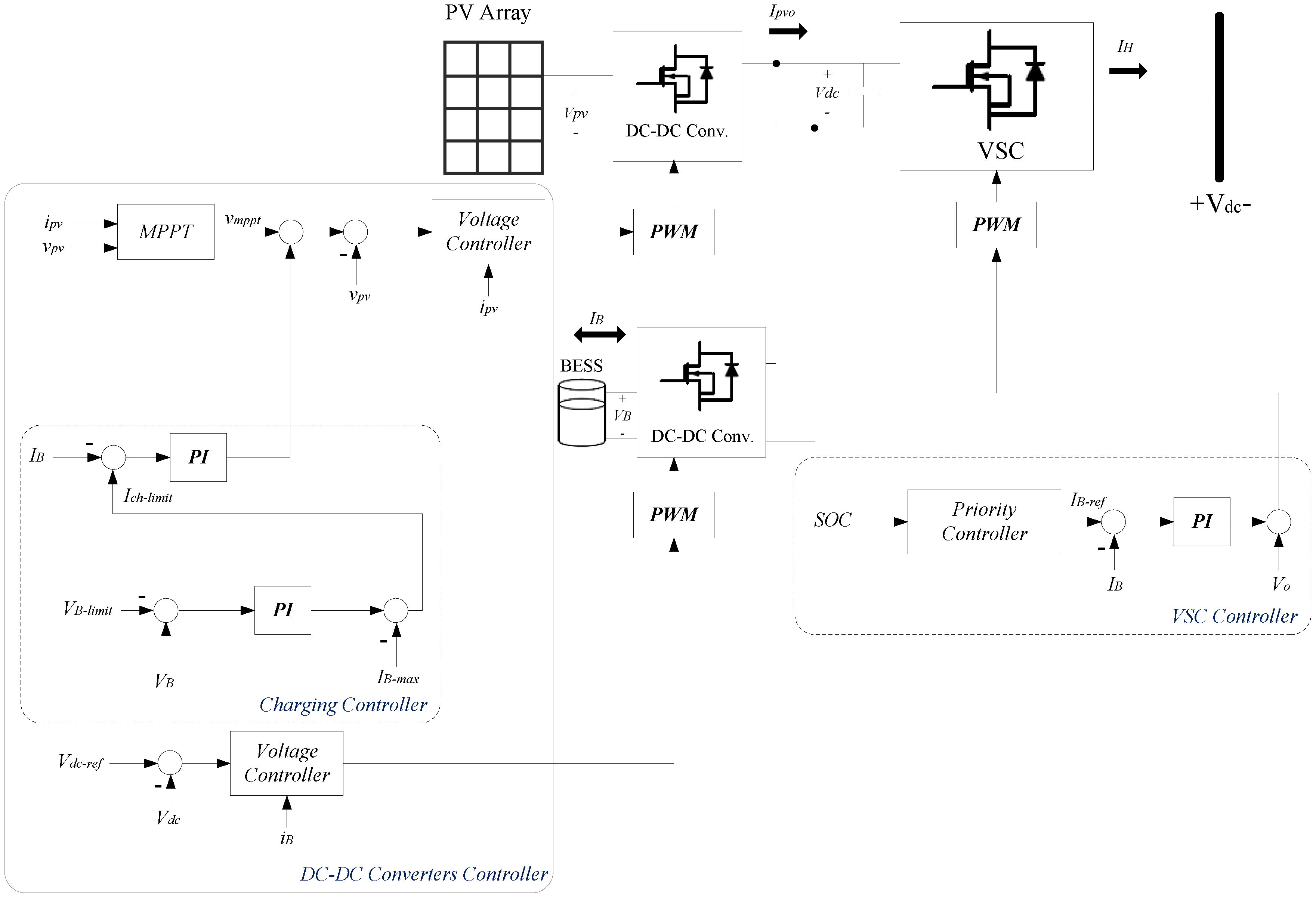
The DC microgrid includes a PV module and BESS in hybrid unit form, and a WTG is supposed in an adaptive droop control microgrid, as shown in Figure 1. The control strategy was designed and implemented so as to be generalized to a vast number of hybrid units and droop control units. Notably, microgrid droop control refers to the third layer of hierarchical control within microgrid energy management system.
Figure 1 illustrates hybrid PV/battery, WTG and linear load in the proposed DC microgrid. The WTG represents a deterministic energy source controlled by droop method with internal control loops in order to meet the load demand and regulate the DC link voltage. It is necessary to mention that in order to simplify calculations, the dynamics of WTG are disregarded and it is supposed as a voltage droop source. The PV unit was regulated by a unidirectional boost converter so as to connect to voltage source converter (VSC). Ipvo is the current injected by the PV module into the DC link while IB represents the current in the BESS terminals. The BESS unit is connected to the DC link by a bidirectional power electronic converter so as to fully control the process of charging and discharging the BESS. Moreover, the use of DC/DC converter increased the flexibility of DC link and BESS voltage selection [20,21]. The hybrid unit is connected to the DC microgrid common bus by a voltage source converter (VSC) which is a DC/DC converter, where control strategy shared between PV module and BESS will control the battery SOC and adjust microgrid voltage by the VSC controllers. In addition, feeder resistance (the resistance between units and DC bus) is ignored. To look at the issue more closely, the proposed structure for the DC microgrid is more suitable for the areas that have direct sun irradiation in most time of the year such as Iran. There are many PV power stations and their structures can be developed and modified to the proposed control strategy to enhance flexibility (real-time control of the SOC and fast response to load demand variations) and efficiency (power loss reduction) of the mentioned power stations. However, in the wind-arise areas, a hybrid structure consisted of the WTG (detailed or phasor model) and BESS unit can be proposed and developed in future contributions.
In fact, the power management strategies in a hybrid DC microgrid can be divided into two subsets, the first is the VSC strategy of managing the power flow between DC microgrid and hybrid unit while directly coordinating the PV and BESS performance in order to support the power balance in the hybrid system. The second subset involves the DC/DC converter control system managing the power flow between the PV and WTG units, BESS and DC microgrid in order to maintain the power balance. Moreover, the DC/DC converter of BESS can regulate the DC link voltage through controlling the reference voltage, whereas the PV converter is controlled to inject the available power into the DC link.

3. Proposed Control Strategy

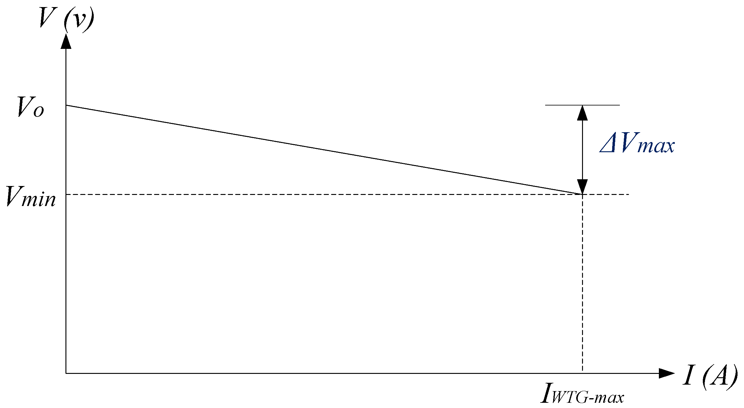
The purpose of VSC or DC/DC converter in the hybrid unit control strategy is the coordination of the hybrid unit performance with the WTG within the DC microgrid. I/V Characteristic curve of WTG is shown in Figure 2. IWTG-max refers to the maximum current that can be produced by WTG unit and delivered to the microgrid.
In fact, VSC is controlled similar to voltage source aimed at adjusting the power or output current of the unit. This target is achieved by controlling the output voltage of the unit as shown in Figure 3. Output current (IH) is regulated indirectly by controlling the battery current (IB) by PI controller. It is also worth noting that DC/DC converter of BESS supports the power balance in the hybrid unit by adjusting the common DC link voltage. Control error (ep) in PI controller input is calculated as follows:
e P = I B - r e f I B = I B - r e f ( I H I p v o )
In order to simplify calculations, the power losses are disregarded [22,23,24,25,26]. Reference current (Iref) is defined as follows:
I r e f = I B - r e f + I p v o
Hence, the control error (ep) can be reformulated as follows:
e p = I r e f I H
From the above equation, it can be concluded that regulation of current IB in the reference value IB-ref is equivalent to regulation of output current of the hybrid unit (IH) in the reference current Iref. Moreover, the controller can be applied directly in order to adjust IH in the reference value Iref using the measured of Ipvo and the reference current value IB-ref. Notably, when the reference value is calculated using the measured Ipvo, the VSC output current is regulated in Iref and converter losses are supplied by the BESS.
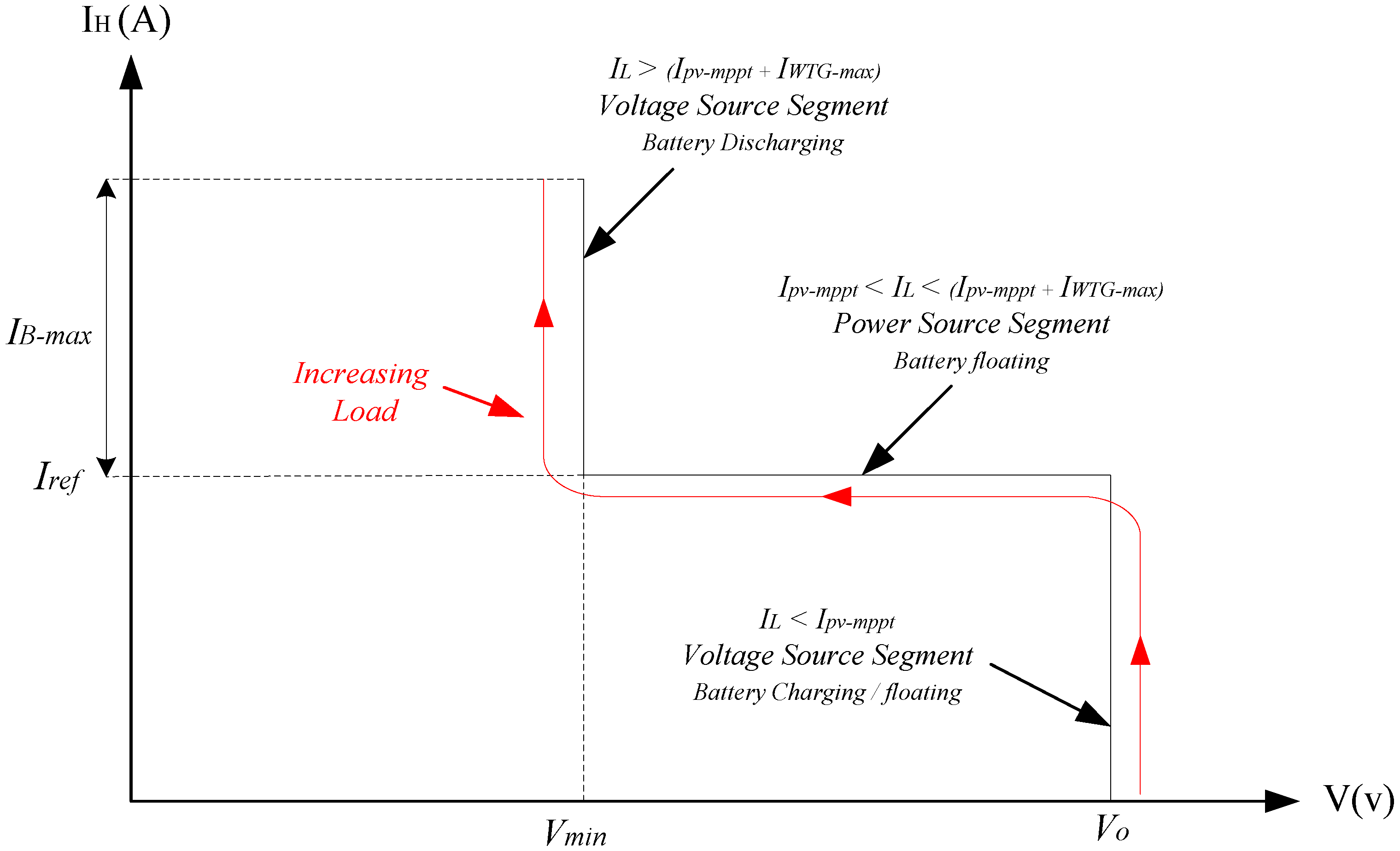
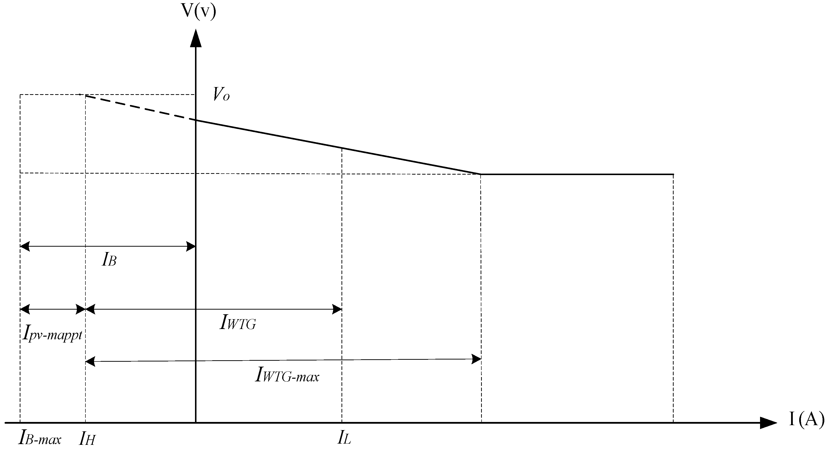
Generally, the output current is controlled by voltage that the operating range of which is limited within Vo and Vmin in order to create I/V characteristic curve of the hybrid unit. The V/I adaptive characteristic of hybrid unit is shown in Figure 4. As can be seen, IL is load demand and IB-max is maximum current supplied or absorbed by the BESS. According to this figure, if the load demand is less than the MPPT of PV units, the hybrid unit will behave as a voltage source in the microgrid, adapting its output power to the load demand. In this scenario, if the battery SOC is less than SOCmin, then battery will be charged, and if the SOC is within the allowable range, the battery will be in floating status. Notably, the battery SOC allowable range in this study was assumed in the range of 20 to 90 percent, as shown in Table 1.
The middle part of the mentioned curve displays a condition where the load demand is between the maximum power generation of PV and WTG. In this scenario, the hybrid unit acts as a controlled power source delivering the MPP power of PV module where the BESS status will be floating. In the third part of the curve, the load demand is higher than the total power generation of DGs. In this situation, the DGs generate their maximum power and BESS supplied the rest of the load demand by discharging. In this mode, the hybrid unit will act as a voltage source in the microgrid while the battery stays in discharging status until SOCmin has been met.
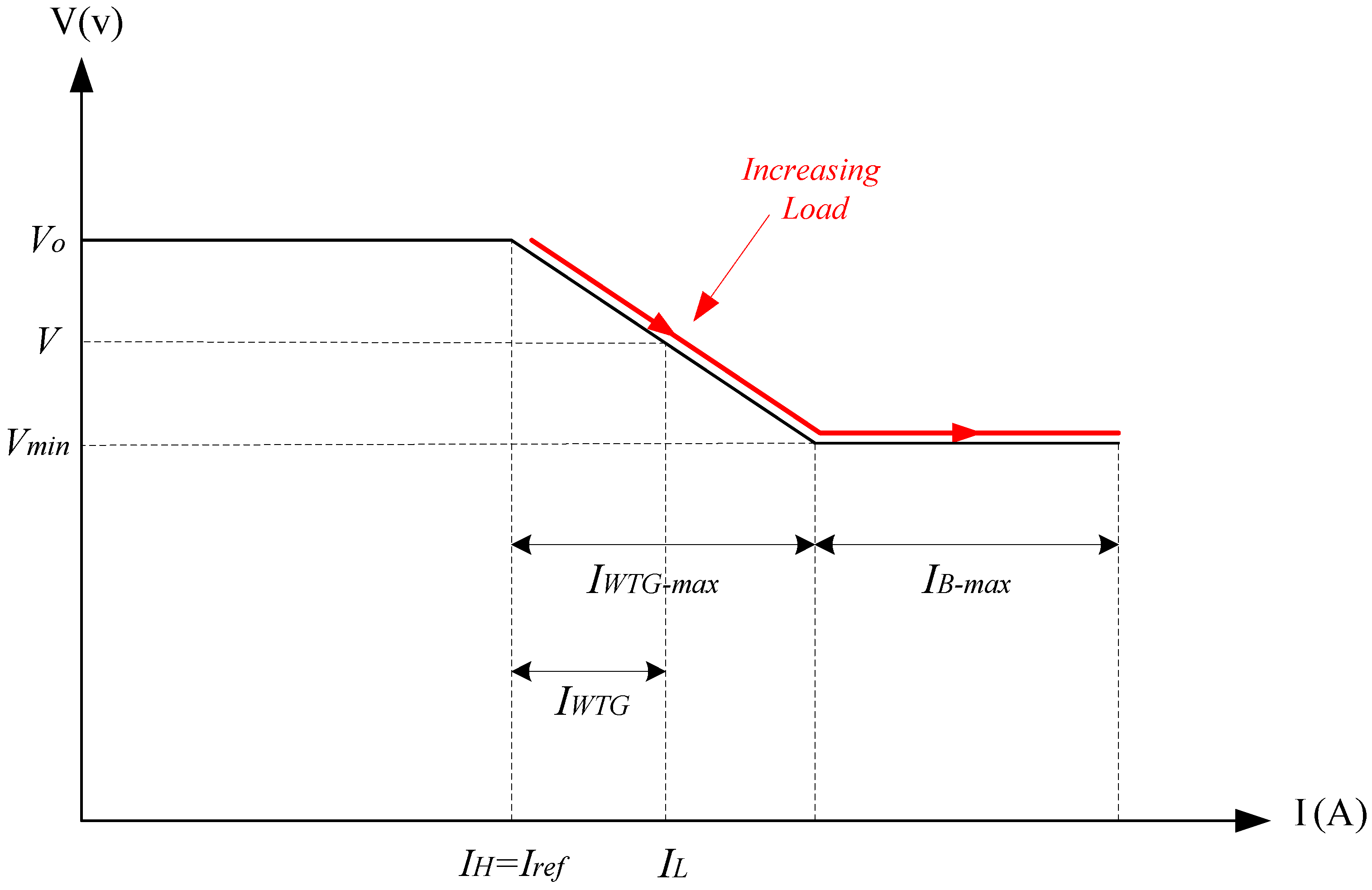
Since the operational voltage of DC microgrid is regulated by WTG according to droop characteristic of this unit and delivered current (IWTG), voltage was considered an independent variable in Figure 4. Unlike the operating point voltage varying based on IWTG, the hybrid unit adjusts IH in Iref using the PI controller. In other words, PI controller is used to compensate the voltage changes due to the droop characteristic of WTG. In order to coordinate the microgrid performance, I/V characteristics of hybrid unit and WTG are combined as shown in Figure 5. The structure of I/V characteristic curve is determined based on the load changes, output power of PV arrays and battery SOC level.
The purpose of VSC controller at any time is to charge the BESS or inject the total power available in the PV module to the DC microgrid. Furthermore, Priority Controller in Figure 3 specified the reference current IB-ref on the basis of battery SOC level and reference value SOCnom in accordance with the BESS charge curve in terms of SOC. Reference level SOCnom is the nominal value of battery charge level while the controller try to reach the SOC to this reference value, so the battery can supply the required power during peak load or reduced generation power of PV. Control loops designed in Figure 3 implement the control strategies on two independent levels:
  • Level 1: At this level, priority of control strategy has been set based on the battery charge or delivery of total power available in PV to the microgrid. In fact, Priority Controller will determine the target based on the battery SOC level.
  • Level 2: Control objectives in this level have been set based on supporting power balance in DC microgrid and preventing the battery SOC from exceeding the allowable range.
For a comprehensive description of the proposed control strategy, the performance of microgrid was divided into two different scenarios based on the battery SOC and control strategy objectives. In both scenarios, the MPPT algorithm was used to extract the maximum power of PV module ( I p v o = I p v - m p p t ). These scenarios will be explored in the next section.

3.1. Nominal Operation Scenario

  • This control strategy becomes operational when S O C S O C n o m . In this case, Priority Controller zeros the IB-ref reference current. Therefore, Iref current is determined on the basis of I p v o = I p v - m p p t . It is noteworthy that Priority Controller has no direct or closed-loop control on the BESS, but the battery current is controlled rather indirectly by injecting current into the microgrid in reference value Iref. This design helps support the power balance in the microgrid and put the supply of load demand on the highest priority in operational scenarios. The system’s operating point can be placed on any part of I/V characteristic of microgrid based on the load demand and Ipv-mppt, which are divided into three subcategories:
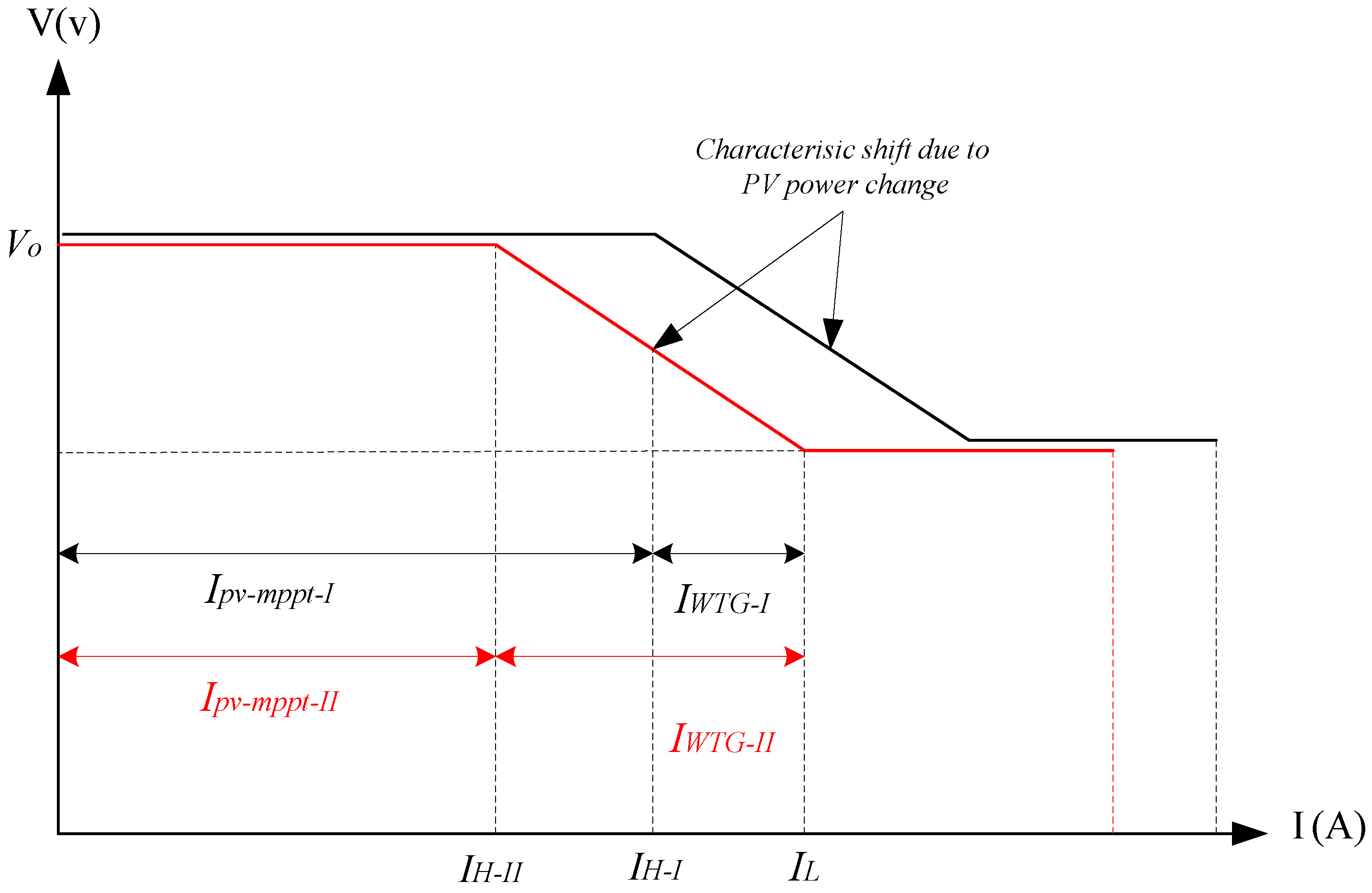
  • I p v - m p p t I L ( I p v - m p p t + I W T G - m a x ) : This mode is equivalent to the middle part of characteristics in Figure 4 and Figure 5, where the hybrid unit injects the total power available in PV unit into the microgrid. The rest of the load demand is supplied by the WTG, maintaining and regulating the microgrid voltage within the allowable range based on the droop characteristic of WTG. Notably, IPv-mppt varied depending on the level of solar radiation and temperature. Hence, any decrease or increase in power generation of PV unit will move I/V characteristic to the left or right in Figure 5, respectively. This effect is shown in Figure 6 where the power output of PV module has decreased from point I to II, which caused power losses of hybrid module from IH-I to IH-II, transferring the entire I/V curve to the left. Moreover, the power output of WTG increases from point I to II in order to compensate the shortage power generation of PV module.
  • I L > ( I p v - m p p t + I W T G - m a x ) : The WTG decreases the voltage in response to the increased load demand based on the droop characteristic, achieving its nominal current at point V = V m i n . If the load increases once again or the PV module generation power decreases, since the load demand (IL) is greater than the total generation of DGs, WTG will attempt to bring the voltage to less than Vmin. Therefore, the hybrid unit begins to adjust the DC bus voltage in Vmin value based on I/V curve suggested in Figure 5. This target is achieved by regulating the output of WTG within its nominal range and supplying the power shortage by the hybrid unit so as to establish a power balance in the microgrid. In fact, the DC-DC converter of BESS injects the excess current in order to adjust the microgrid voltage within the allowable range. Notably, in this scenario, if the load current exceeds the nominal current of the battery and the battery is fully discharged, the load shedding scenario should be implemented, but it is beyond the scope of this paper.
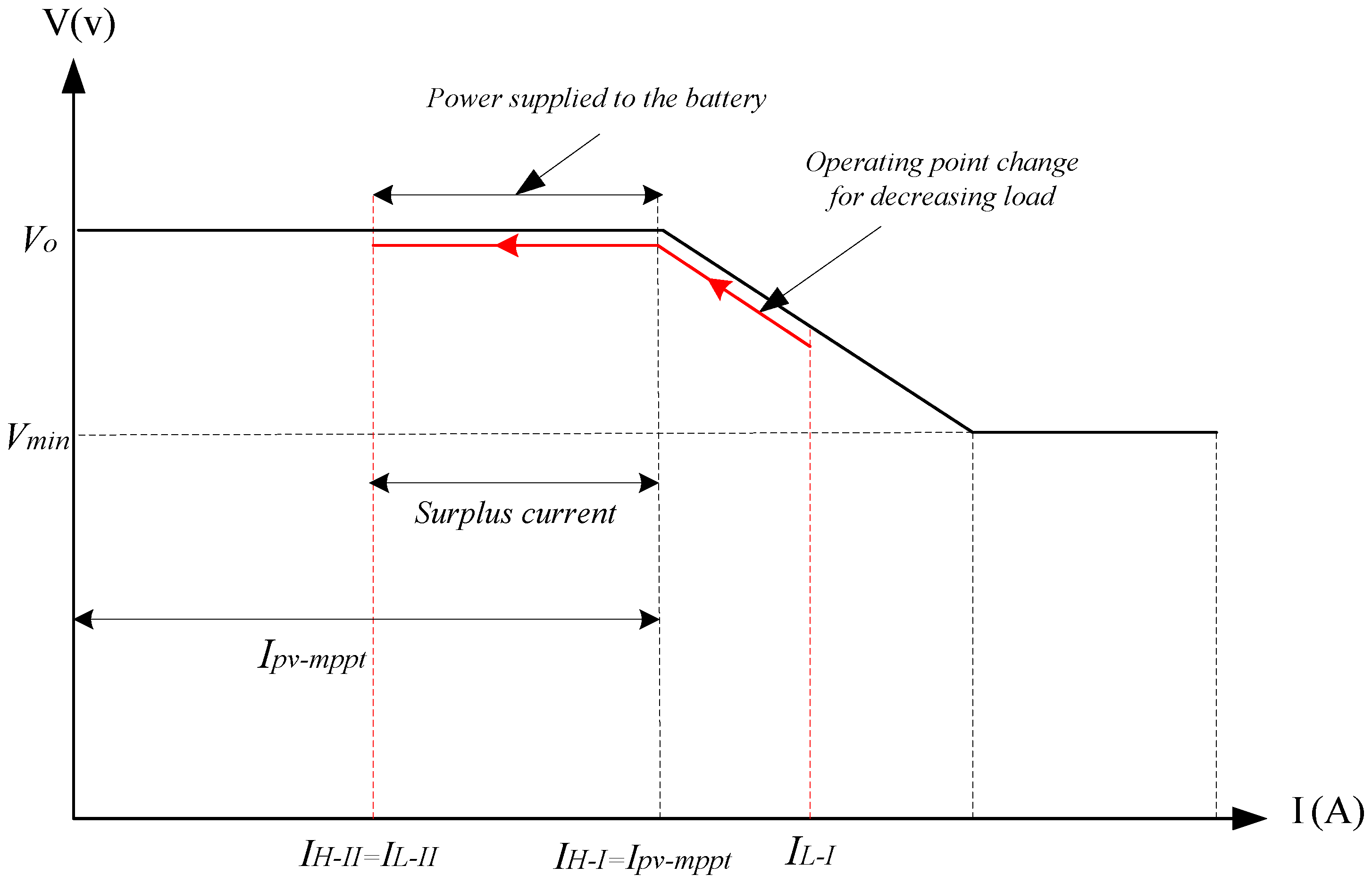
  • I L < I p v - m p p t : In this mode, since the hybrid unit inclines at any moment to inject current Ipv-mppt into the microgrid and this current is more than the load demand, the current generated by WTG becomes zero, supplying the total load demand by the hybrid unit in V = V 0 . Moreover, since the range of Ipv-mppt produced by the hybrid unit is more than the load demand, the microgrid voltage tends to rise to more than nominal value Vo. In this situation, the DC/DC converter absorbs the excess current ( I p v - m p p t I L ) and charge the battery (if necessary) to regulate the DC link voltage within the allowable range or the MPPT controller of PV unit transfers the operating point out to the MPP region, thus adapting the generation power to the load demand. This mechanism can maintain the power balance in the hybrid unit and microgrid. This scenario is shown in Figure 7 where the load demand drops from IL-I to IL-II. Notably, although the target in this mode is to inject the total power of PV module into the microgrid, the top priority is to establish the power balance in the microgrid. This can be fulfilled by supplying the load demand and storing the excess energy if necessary.

3.2. BESS Charging Scenario

This control strategy is operated when S O C < S O C n m i n . This strategy can also be applied when the SOC is less than SOCmax and there is excess energy in the system. Therefore, the reference current IB-ref is regulated in the value of −IB-max (maximum charging current) and reference Iref in the value of ( I p v o I B - m a x ).
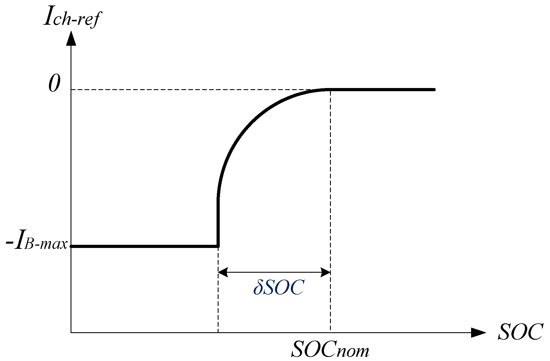
Using a constant charge curve SOC/IB-ref similar to Figure 8 as Priority Controller, the BESS can be analyzed and modeled within the hybrid unit [27]:
I B - r e f = I B - m a x + I B - m a x ( 1 e S O C S O C n o m + δ S O C δ S O C k δ )
In the above equation, SOCnom represents the reference BESS charge level that the controller of the BESS tends to reach at this SOC level. When the BESS charge level reaches SOCref, the constant Kδ will determine how fast the reference charge current Ich-ref decreases to zero (i.e., battery discharge rate). Both Kδ and δSOC are selected according to battery specification and design preference.
The proposed control strategy in this scenario is divided into two parts:
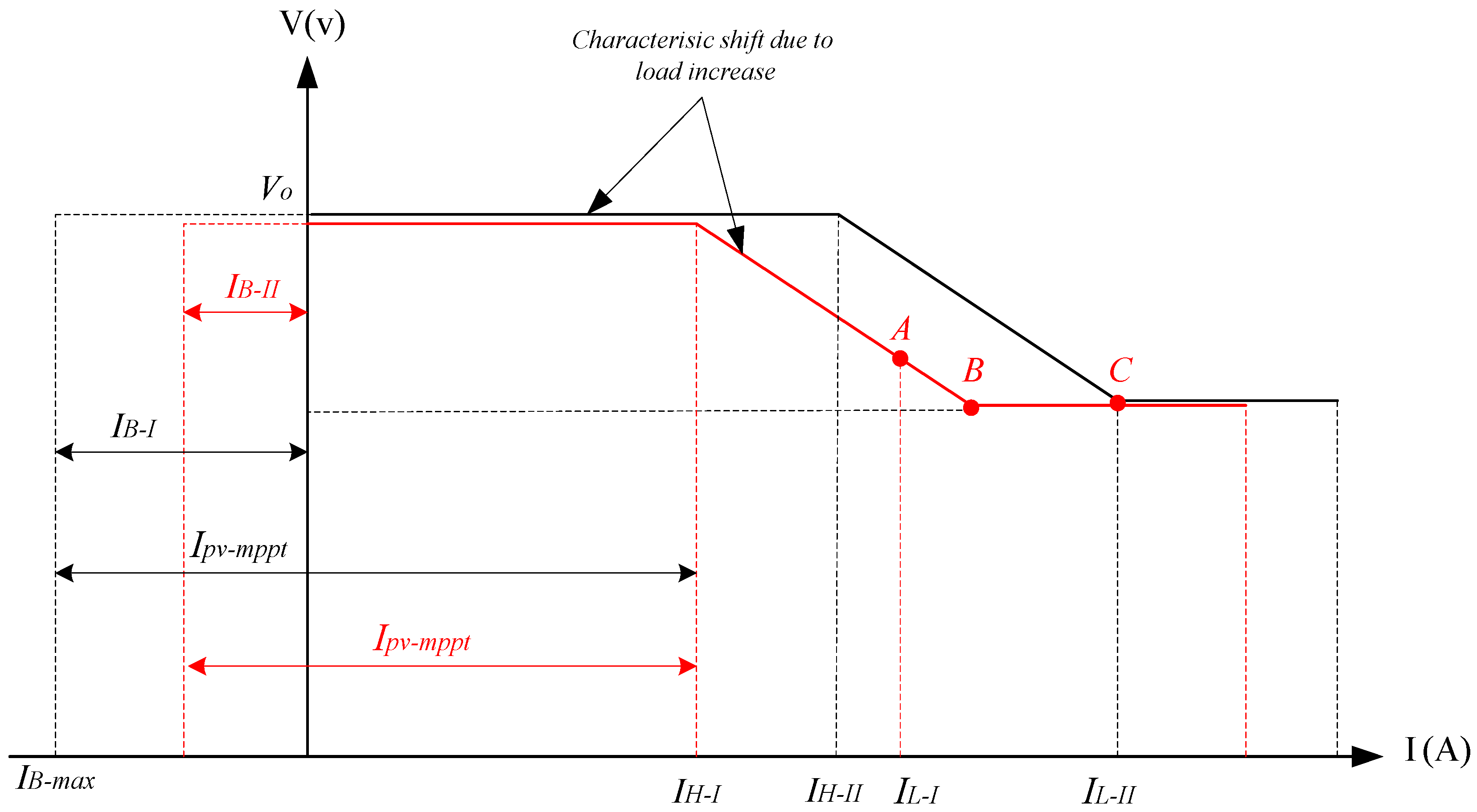
  • I B - m a x I p v - m p p t : In this case, the current produced by PV unit is sufficient for battery charge and excessive current is injected into the microgrid. Current injection into the microgrid (IH) is derived from the difference ( I p v - m p p t I B - m a x ). In fact, when the VSC injects the current into the microgrid, the DC/DC converter of BESS injects the PV unit’s remaining power into the BESS in order to regulate the DC link voltage. Hence, the battery charging process can be fulfilled by indirectly controlling the power injected into the DC microgrid. It is noteworthy, however, the major target of control strategy in this scenario involves battery charge, and top priority is to support the establishment of power balance within the microgrid for decentralized controlling of the DC microgrid. Figure 9 illustrates the displacement of operating point and I/V characteristic in order to support the power balance during battery charging.
    As shown in the above figure, the battery is first charged separately by PV Unit with current I B - I = I B - m a x as remaining current of PV supplies the load demand IL-I. The rest of the load demand will be supplied by WTG according to its droop characteristic (point A). WTG can supply any load rise until to the point B and Vmin. If the load demand increases beyond this point and to IL-II, the WTG will attempt to decrease the voltage based on the characteristic droop to below Vmin. Therefore, the hybrid unit in this scenario increases its output from IH-I to IH-II in order to stabilize and regulate the voltage range. Furthermore, the battery charge current decreases to IB-II in order to regulate the DC link voltage. The hybrid unit continues to supply the load demand until the maximum current injection (Ipv-mppt); therefore, the charge current becomes zero. Any increase in the load demand will be supplied by the BESS to support the power balance in the microgrid as described in Figure 5.
  • I B - m a x > I p v - m p p t : In this case, the reference current Iref is negative and the hybrid unit absorbs the current difference ( I p v - m p p t I B - m a x ) so as to charge the battery in maximum current. This is equivalent to moving the I/V characteristic to the left according to Figure 10. In this situation, the hybrid unit acts as a load. The WTG will supply the battery charge current and any increase in the load demand up until its nominal current.

4. Coordination of Control System

In the scenario where the PV module power generation is greater than the load demand, the hybrid unit stores the excess power in the battery, which might lead the SOC level to exceed the SOCmax limit. This condition occurs when the excess power of PV ( I p v - m p p t I L ) is greater than the current IB-max of the battery unit. This can impair the battery voltage and destroy its cells [28]. It is crucial to adopt a suitable controller for monitoring the BESS charge status. Since this investigation intended to coordinate the performance of the hybrid unit in DC microgrid, there was a two-stage charge controller involved in achieving this target. This controller is able to combine different charging curves through the battery SOC or DC link voltage so as to adjust the reference charge current [29,30]. Since the available power for BESS charging varies depending on the PV power generation and load demand, therefore the proposed controller was implemented only to regulate Ich-limit based on battery voltage as shown in Figure 3. Moreover, the internal control loop IB in Figure 3 was adopted to control the charging current within the allowable range and prevent its value exceeding Ich-limit at every moment. When the battery voltage is reduced to less than VB-limit, the PI controller output will regulate the charging current Ich-limit on the value of −IB-max. This behavior will continue until the battery voltage is increased to the reference value. When the battery voltage exceeds the value of VB-limit, the PI controller curtails the reference charging current (Ich-limit) in order to adjust the battery voltage. If the load decreases or the battery voltage increases, so that IB exceeds reference Ich-limit, the PI controller will adjust the charge current of PV module so as to follow the reference charge current Ich-limit. In fact, the controller transfers the operating point of the PV module outside the maximum power point (MPP) so as to reduce the power generation of PV, thus stabilizing the battery charge current in the value of IB-ref. Throughout this process, the MPPT algorithm is disabled and the range of VMPPT stays in the last fixed value before disabling the algorithms. It is noteworthy that MPPT algorithm in this paper is based on Perturb and Observe method that follows and monitors the MPP point in the power-voltage curve of PV module. Now, if the BESS current falls again below Ich-limit due to increased load demand, the PI controller will transfer the operating point of PV unit to the MPP region, so as to increase the generation power of PV, thus stabilizing the current IB in Ich-limit. In both the above processes, the hybrid unit supplies the load demand. If the load demand increases or generation power of PV decreases according to the reduced solar radiation, then the controller will transfer the PV operating point to the MPP point, thus zeroing the PI controller output. Any increase in load demand beyond the maximum power of PV module will be supplied by the WTG.

5. Simulation Results

A DC microgrid composed of a PV/BESS hybrid module, WTG and linear load was simulated in MATLAB/SIMULINK so as to evaluate the performance of proposed control strategy. Microgrid parameters have been presented in Table 1. The proposed strategy was assessed through several operational scenarios such as applying changes in the level of PV generation power, load demand and battery charging scenario.
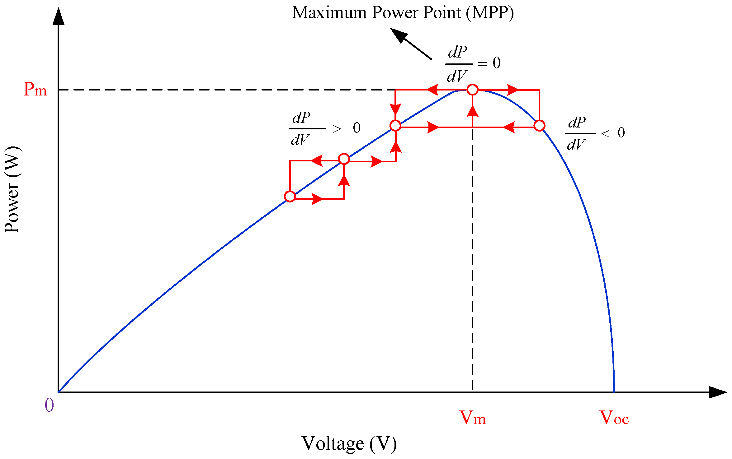
This study involved the MPPT algorithm based on conventional Perturb and Observe method in order to extract the maximum power of PV array. According to Figure 11, it can be shown that d P d V becomes zero at the maximum power point, before which the value of power becomes positive and then will be negative. In addition, if d P d V is positive, the algorithm progresses on the power-voltage curve by increasing the voltage until it reaches d P d V = 0 ; and if d P d V is negative, the algorithm moves in the opposite direction to the point where the power-voltage variations are zero, selecting that point as the maximum power point.
The performance of the proposed decentralized control strategy is simulated and validated through MATLAB/SIMULINK under the nominal scenario with changes in both load and generation, under the charging scenario and the transition between operating scenarios.

5.1. Nominal Scenario

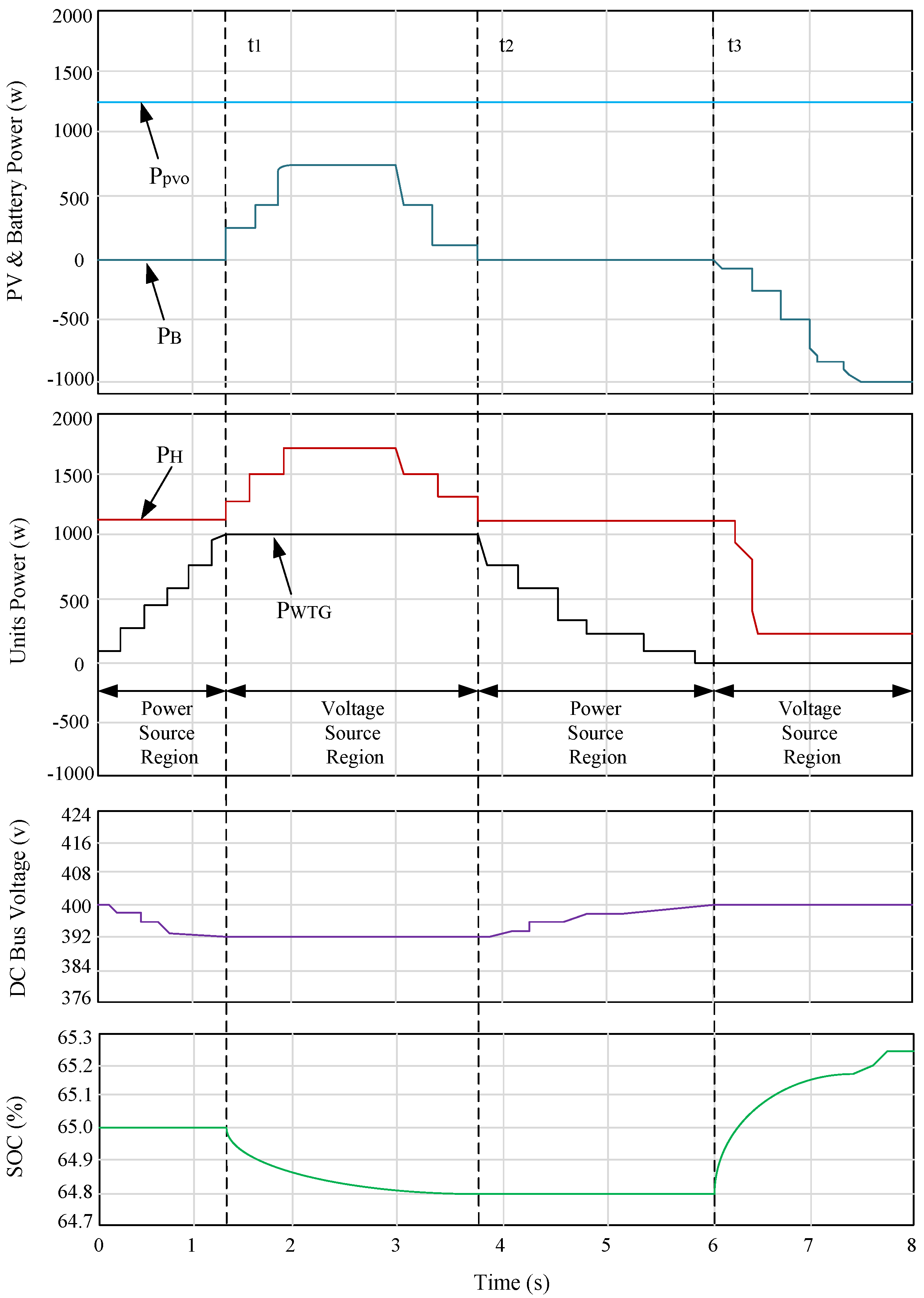
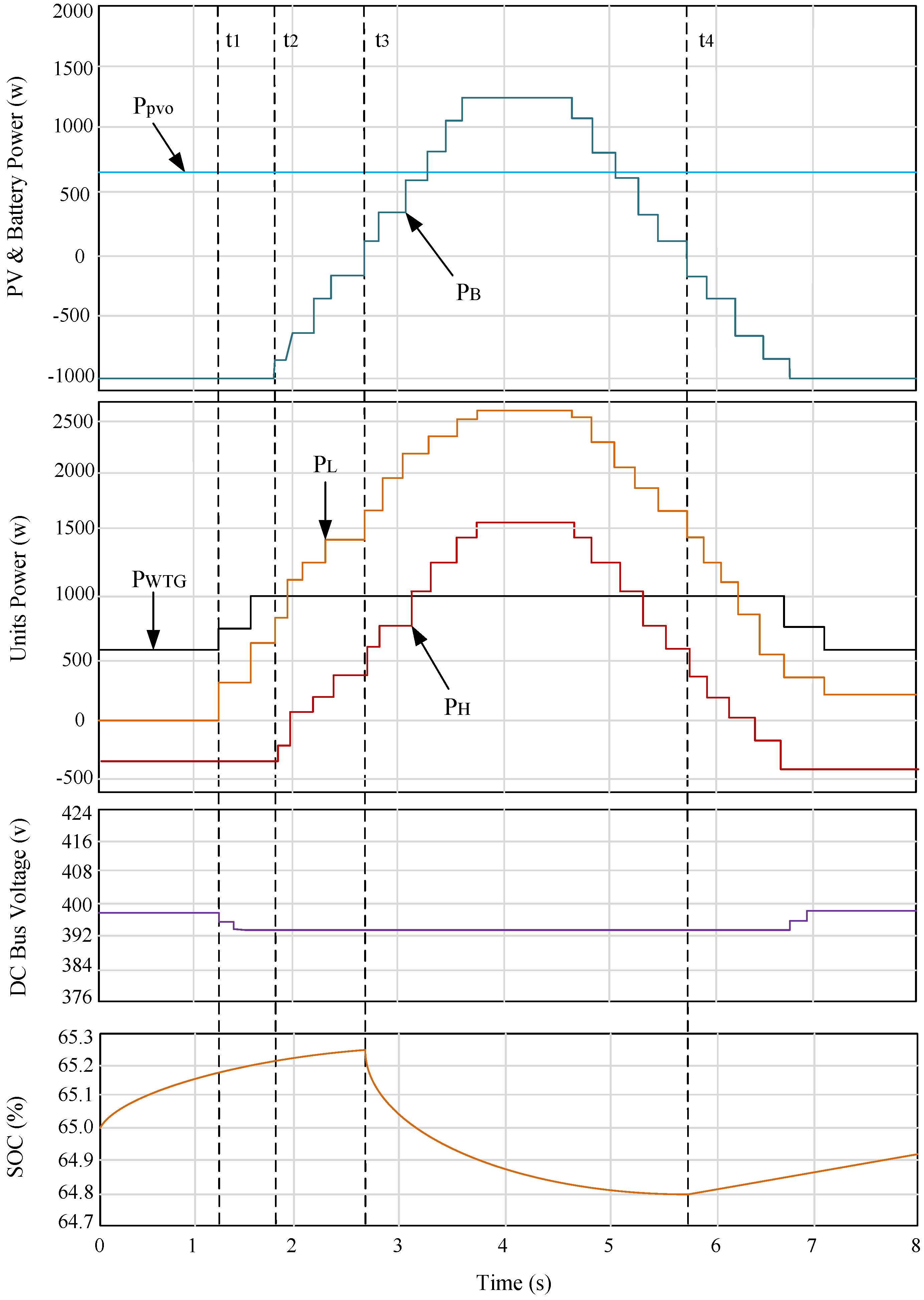
Performance of the proposed control strategy during the nominal operating scenario in response to load changes is illustrated in Figure 12. During this scenario, the SOC is higher than SOCnom, which is set to 65%. To effectively illustrate the performance, the system behavior is divided into four regions. Between t = 0 and t = t1, the hybrid unit delivers all available PV power to the DC microgrid by regulating the battery power at PB = 0 W. Therefore, the hybrid unit appears in the microgrid as a power controlled source. On the other hand, the increasing load demand is met by the WTG unit. This results in dropping the voltage in response to the increasing load. The WTG unit continues to supply the increasing load demand until it reaches its maximum power rating of 1000 W at t = t1. At this point, the voltage reaches its minimum limit of Vmin, i.e., 392 V. From t = t1 to t = t2, the load increases beyond the power available from the PV and the WTG unit combined, i.e., ( P L > P pv - mppt + P WTG - max ). As discussed before and displayed by the microgrid I/V characteristics, the hybrid unit starts regulating the operating voltage at Vmin, which results in limiting the PWTG at PWTG-max. Consequently, the hybrid unit operates as a voltage source, and therefore matches the varying load by supplying the deficit power from the BESS, resulting in a drop in the SOC. At t = t2, the load demand drops below the total of ( P pv - mppt + P WTG - max ), and therefore the hybrid unit returns to operating as a power controlled source, while the WTG unit supplies the rest of the load demand. The load demand continues to drop until P WTG = 0 W at t = t3. For t ≥ t3, the load demand decreases below the available PV power, i.e., P L < P pv - mppt . Consequently, the hybrid unit autonomously starts acting as a voltage source, while regulating the voltage at V = V 0 and matching the available load demand in the DC microgrid. As can be seen in Figure 12, the surplus power from the PV is absorbed by the BESS to maintain the power balance in the hybrid unit as well as in the DC microgrid.
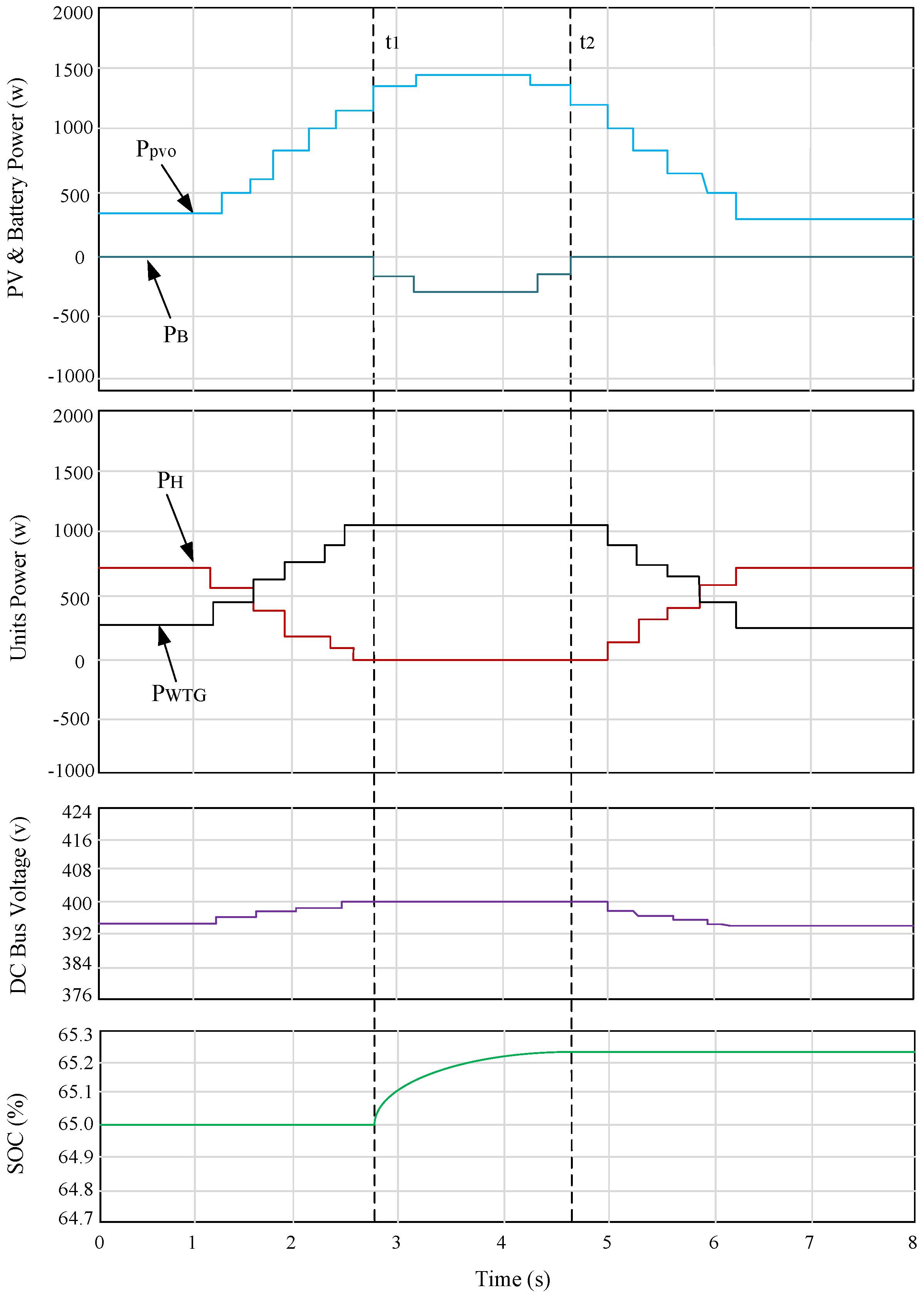
Performance of the proposed control strategy in response to PV power variations is illustrated in Figure 13. In this simulation, the load is kept constant around 1000 W, and the PV power is varied by changing the solar irradiance from 200 W/m2 to 1000 W/m2. Between t = 0 and t = t1, it is shown in Figure 13 that the hybrid unit tracks and supplies all the available PV power to the DC microgrid while regulating the BESS power at P B - ref = 0 W. Since the load demand is kept constant, the output power from the WTG unit is reduced in response to the increasing power from the hybrid unit, which operates as a power controlled source in this period. The output power PH continues to increase with increasing PV power until it supplies the entire load, and PWTG reduces to zero. The increase in the PV power beyond this limit (for t ≥ t1) results in the controller PI saturating at V = V 0 . This causes the hybrid unit to behave as a voltage source and therefore matches the load demand. This shows how the highest priority of maintaining the power balance in the DC microgrid is achieved by the control strategy autonomously. Consequently, the surplus PV power is absorbed by the BESS, through the DC-DC converter, which is responsible for regulating the DC-link voltage. The BESS continues to store the surplus energy until the PV power drops below the load demand.

5.2. Charging Scenario

The performance of the proposed strategy during the charging operating scenario is illustrated in Figure 14. In this scenario, the objective is to charge the BESS at PB-max (−1000 W). Since the available PV power is less than PB-max, the rest of the charging power and the losses are imported from the DC microgrid. In this case, the hybrid unit appears as a load in the microgrid, which is equivalent to shifting the I/V characteristics to the left, as explained in Figure 10. When the load starts increasing at t = t1, the WTG unit starts supplying the increased load demand, while the BESS is still being charged at its maximum rating, until PWTG reaches PWTG-max at t = t2. As the load increases beyond this point, the hybrid unit starts regulating the voltage at Vmin, due to the chosen limit of the controller PI output. This results in limiting the output of the WTG unit at its rated power, while reducing the power flow into the hybrid unit until P H = 0 W. This happens because the hybrid unit operates as a voltage controlled source that regulates the voltage. On the other hand, the output power of the WTG units is regulated at its rating, i.e., it starts operating as power controlled source. Any increase in the load demand beyond this point will be supplied by the hybrid unit as the I/V characteristic continues to shift to the right, until all the PV power is being delivered to the load demand, which happens at t = t3. Any further increase in the load demand will be supplied by the BESS as discussed before. The control strategy resumes charging the BESS after the load demand drops below the total generation as shown in Figure 14 for t > t4.

5.3. Transition between Operating Scenarios

The performance of the proposed strategy during a transition from charging scenario to the nominal operating scenario is illustrated in Figure 15. In this simulation, δSOC is set to 0.1%, while SOCnom is set to 65%. Initially, the system is operating in the charging scenario while the BESS is being charged at its maximum rating. The SOC continues increasing until it reaches the limit of ( S O C n o m δ S O C ), i.e., 64.9% at t = t1. At this moment, the charging priority controller starts reducing the reference PB-ref exponentially as a function of the rising SOC (see Figure 8). As can be seen in Figure 15, the charging power is reduced and, consequently, the hybrid unit output PH increases until all the available PV power is delivered to the DC microgrid. Moreover, the load PL is stepped up and down several times to examine the performance of the power control loop during the transition period in response to load disturbances. As shown in Figure 15, the hybrid unit continues to operate as a power controlled source until t = t2. At this point, the load demand is dropped below the supplied PV power and therefore, the hybrid unit autonomously starts to operate as a voltage source to match the available load demand while regulating the voltage at Vo.
As mentioned in the last paragraph of the Introduction, the main contribution of this investigation is to satisfy all of the power management objectives in microgrid, such as voltage regulation, establishing power balance and control of the BESS SOC, concurrently. Overall, Table 2 shows the contributions and advantages of the proposed method in comparison to other references. According to Table 2, the proposed method has the all of the advantages in microgrid power management targets in comparison with the other references in the same field. For instance, the proposed method covers all the power management objectives and has development ability for greater number of DG units in network enlargement, whereas this feature is usually disregarded in the control system design in microgrids. In addition, power balance is ignored in References [31,32], which may affect microgrid stability, and power loss reduction is neglected in References [32,33], which can decrease system efficiency and increase power generation costs.

6. Conclusions

This paper proposed a decentralized control strategy for power management of DC microgrid composed of a hybrid PV/battery unit and WTG in isolated mode. Unlike the conventional methods of PV control as a current source, the hybrid PV/battery was controlled as a voltage source following the adaptive I/V characteristic curve. Based on the system simulation and newly proposed control strategy in MATLAB/SIMULINK, it was found that adaptive I/V characteristic can be applied independently to the microgrid. Hence, the hybrid unit and WTG can inject their maximum powers into the microgrid, supplying the load demand and charging the BESS. Moreover, it supported the power balance in the DC microgrid, fulfilling the battery’s SOC constraints and regulating the DC bus voltage. In the case that load demand exceeds the maximum generation power of the PV unit, the WTG will supply the power shortage. In addition, in the case that load demand is more than the total power generation of DGs, the BESS will begin to discharge in order to regulate the DC bus voltage and maintain power balance in the microgrid. The proposed strategies were performed without the need for communication links or any centralized energy management system.

Author Contributions

Mehrdad Beykverdi is the main author of this work. This paper further elaborates on some of the results from his Ph.D. dissertation. Abolfazl Jalilvand supervised the project and supported Mehrdad Beykverdi’s research in terms of both scientific and technical expertise. Mehdi Ehsan assisted in the results analysis and interpretation. The manuscript was written by Mehrdad Beykverdi and was reviewed and revised by Abolfazl Jalilvand.

Conflicts of Interest

The authors declare no conflict of interest.

References

  1. Kahrobaeian, A.; Mohamed, Y.I. Network-based hybrid distributed power sharing and control for islanded microgrid systems. IEEE Trans. Power Electron. 2015, 30, 603–617. [Google Scholar] [CrossRef]
  2. Xiao, J.; Wang, P.; Setyawan, L. Multilevel energy management system for hybridization of energy storages in DC microgrids. IEEE Trans. Smart Grid. 2016, 7, 847–856. [Google Scholar] [CrossRef]
  3. Zeng, Z.; Yang, H.; Tang, S.; Zhao, R. Objective-oriented power quality compensation of multifunctional grid-tied inverters and its application in microgrids. IEEE Trans. Power Electron. 2015, 30, 1255–1265. [Google Scholar] [CrossRef]
  4. Du, W.; Jiang, Q.; Erikson, M.; Lasseter, R. Voltage-source control of PV inverter in a CERTS microgrid. IEEE Trans. Power Deliv. 2014, 29, 1726–1734. [Google Scholar] [CrossRef]
  5. Chen, D.; Xu, L.; Yao, L. DC voltage variation based autonomous control of DC microgrids. IEEE Trans. Power Deliv. 2013, 28, 637–648. [Google Scholar] [CrossRef]
  6. Olivares, D.; Canizares, C.; Kazerani, M. A centralized energy management system for isolated microgrids. IEEE Trans. Smart Grid 2014, 5, 1864–1875. [Google Scholar] [CrossRef]
  7. Anand, S.; Fernandes, B.G.; Guerrero, J. Distributed control to ensure proportional load sharing and improve voltage regulation in low-voltage DC microgrids. IEEE Trans. Power Electron. 2013, 28, 1900–1913. [Google Scholar] [CrossRef]
  8. Che, L.; Shahidehpour, M. DC microgrids: Economic operation and enhancement of resilience by hierarchical control. IEEE Trans. Smart Grid 2014, 5, 2517–2526. [Google Scholar]
  9. Tan, K.T.; Sivaneasan, B.; Peng, X.Y.; So, P.L. Control and operation of a DC grid-based wind power generation system in a microgrid. IEEE Trans. Energy Conversion. 2016, 31, 496–505. [Google Scholar] [CrossRef]
  10. Shafiee, Q.; Dragicevic, T.; Guerrero, J.V.J.M. Hierarchical control for multiple DC microgrids clusters. IEEE Trans. Energy Convers. 2014, 29, 922–933. [Google Scholar] [CrossRef]
  11. Jin, C.; Wang, P.; Xiao, J.; Tang, Y.; Choo, F.H. Implementation of hierarchical control in DC microgrids. IEEE Trans. Ind. Electron. 2014, 61, 4032–4042. [Google Scholar] [CrossRef]
  12. Eghtedarpour, N.; Farjah, E. Distributed charge/discharge control of energy storages in a renewable-energy-based DC microgrid. IET Renew. Power Gener. 2014, 8, 45–57. [Google Scholar] [CrossRef]
  13. Caldognetto, T.; Tenti, P. Microgrids operation based on master-slave cooperative control. IEEE J. Emerg. Sel. Top. Power Electron. 2014, 2, 1081–1088. [Google Scholar] [CrossRef]
  14. Majumder, R. A hybrid microgrid with DC connection at back to back converters. IEEE Trans. Smart Grid 2014, 5, 251–259. [Google Scholar] [CrossRef]
  15. Paquette, A.; Reno, M.; Harley, R.; Divan, D. Sharing transient loads: Causes of unequal transient load sharing in islanded microgrid operation. IEEE Ind. Appl. Mag. 2014, 20, 23–34. [Google Scholar] [CrossRef]
  16. Eghtedapour, N.; Farjah, E. Power control and management in a hybrid AC/DC microgrid. IEEE Trans. Smart Grid 2014, 5, 1494–1505. [Google Scholar] [CrossRef]
  17. Che, L.; Khodayar, M.; Shahidehpour, M. Only connect: Microgrids for distribution system restoration. IEEE Power Energy Mag. 2014, 12, 70–81. [Google Scholar]
  18. Lu, X.; Sun, K.; Guerrero, J.M.; Vasquez, J.C.; Huang, L. State of charge balance using adaptive droop control for distributed energy storage systems in DC micro-grid applications. IEEE Trans. Ind. Electron. 2014, 61, 2804–2815. [Google Scholar] [CrossRef]
  19. Augustine, S.; Mishra, M.K.; Lakshminarasamma, N. Adaptive droop control strategy for load sharing and circulating current minimization in low-voltage standalone DC microgrid. IEEE Trans. Sustain. Energy 2015, 6, 132–141. [Google Scholar] [CrossRef]
  20. Jiang, W.; Fahimi, B. Active current sharing and source management in fuel cell-battery hybrid power system. IEEE Trans. Ind. Electron. 2010, 57, 752–761. [Google Scholar] [CrossRef]
  21. Li, Y.W.; Kao, C.N. An accurate power control strategy for power electronic-interfaced distributed generation units operating in low-voltage multi-bus microgrid. IEEE Trans. Power Electron. 2009, 24, 2977–2988. [Google Scholar]
  22. Belvedere, B.; Bianchi, M.; Borghetti, A.; Nucci, C.A.; Paolone, M.; Peretto, A. A microcontroller-based power management system for a standalone microgrids with hybrid power supply. IEEE Trans. Sustain. Energy 2012, 3, 422–431. [Google Scholar] [CrossRef]
  23. Tan, K.T.; Peng, X.Y.; So, P.L.; Chu, Y.C.; Chen, M.Z.Q. Centralized control for parallel operation of distributed generation inverters in microgrids. IEEE Trans. Smart Grid 2012, 3, 1977–1987. [Google Scholar] [CrossRef] [Green Version]
  24. Wang, B.; Sechilariu, M.; Locment, F. Intelligent DC microgrid with smart grid communications: Control strategy consideration and control. IEEE Trans. Smart Grid 2012, 3, 2148–2156. [Google Scholar] [CrossRef]
  25. Tan, K.T.; So, P.L.; Chu, Y.C.; Chen, M.Z.Q. Coordinated control and energy management of distributed generation inverters in microgrid. IEEE Trans. Power Deliv. 2013, 28, 704–713. [Google Scholar] [CrossRef] [Green Version]
  26. Chen, Y.K.; Wu, Y.C.; Song, C.C.; Chen, Y.S. Design and implementation of energy management system with fuzzy control for DC microgrid systems. IEEE Trans. Power Electron. 2013, 28, 1563–1570. [Google Scholar] [CrossRef]
  27. Thounhomg, P.; Rael, S.; Davat, B. Control algorithm of fuel cell and batteries for distributed generation systems. IEEE Trans. Energy Convers. 2008, 23, 148–155. [Google Scholar]
  28. Koutroulis, E.; Kalaitzakis, K. Novel battery charging regulation system for photovoltaic applications. IEEE Proc. Electr. Power Appl. 2004, 151, 191–197. [Google Scholar] [CrossRef]
  29. Cao, Y.; Tang, S.; Li, C.; Zhang, P.; Tan, Y.; Zhang, Z.; Li, J. An optimized EV charging model considering Tou price and SOC curve. IEEE Trans. Smart Grid 2012, 3, 85–94. [Google Scholar] [CrossRef]
  30. Miao, Z.; Xu, L.; Disfani, V.R.; Fam, L. An SOC-based energy management system for microgrids. IEEE Trans. Smart Grid 2014, 5, 966–973. [Google Scholar] [CrossRef]
  31. Xu, L.; Chen, D. Control and operation of DC microgrid with variable generation and energy storage. IEEE Trans. Power Deliv. 2011, 26, 2513–2522. [Google Scholar] [CrossRef]
  32. Guerrero, J.M.; Vasquez, J.C.; Matas, J.; Castilla, M.; Vicuna, L.G.D. Hierarchical control of droop-controlled AC and DC microgrids—A general approach to standardization. IEEE Trans. Ind. Electron 2011, 58, 158–172. [Google Scholar] [CrossRef]
  33. Gu, Y.; Xiang, X.; Li, W.; He, X. Mode-adaptive decentralized control for renewable DC microgrid with enhanced reliability and flexibility. IEEE Trans. Power Electron. 2014, 29, 5072–5084. [Google Scholar] [CrossRef]
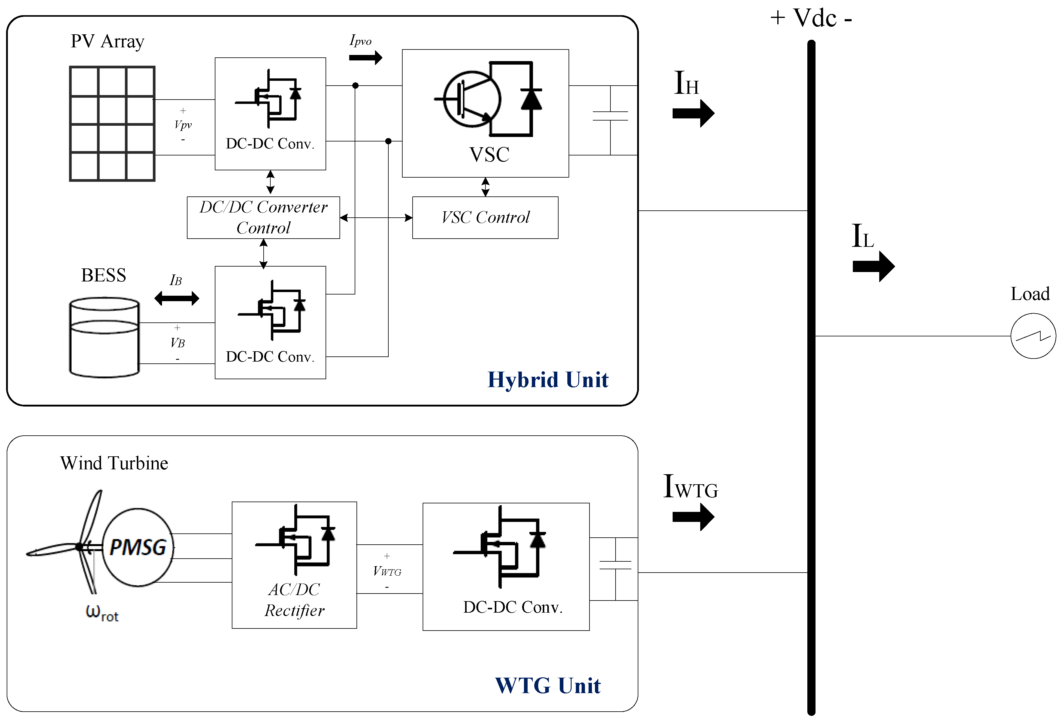
Figure 1. Block diagram of proposed DC microgrid.
Energies 09 00859 g001
Figure 2. Current/voltage characteristics of WTG.
Energies 09 00859 g002
Figure 3. Proposed control strategy.
Energies 09 00859 g003
Figure 4. Equivalent voltage/current characteristics of the hybrid unit.
Energies 09 00859 g004
Figure 5. Equivalent current/voltage characteristics of the DC microgrid with the increasing load trajectory.
Energies 09 00859 g005
Figure 6. I/V characteristics of the microgrid in the nominal operating scenario when PV power decreases.
Energies 09 00859 g006
Figure 7. I/V operating point trajectory when the load changes from IL-I to IL-II, where IL-II < Ipv-mppt.
Energies 09 00859 g007
Figure 8. SOC/IB-ref characteristic curve of the BESS.
Energies 09 00859 g008
Figure 9. I/V characteristic illustrating the battery charging scenario when the load increases.
Energies 09 00859 g009
Figure 10. I/V characteristic during battery charging scenario when I B - m a x > I p v - m p p t .
Energies 09 00859 g010
Figure 11. P & O MPPT algorithm mechanism.
Energies 09 00859 g011
Figure 12. Simulation results of proposed strategy during the nominal operating scenario in response to load changes.
Energies 09 00859 g012
Figure 13. Simulation results of the proposed strategy during the nominal operating scenario in response to PV power changes.
Energies 09 00859 g013
Figure 14. Simulation results of the proposed control strategy during the charging operating scenario.
Energies 09 00859 g014
Figure 15. Simulation results of the proposed control strategy during a transition from the charging scenario to the nominal operating scenario.
Energies 09 00859 g015
Table 1. DC microgrid parameters.
ParameterSymbolValue
DC bus voltage Ref.Vdc-ref400 V
Low threshold DC voltageVL392
High threshold DC voltageVH408
PV maximum PowerPpv-mppt1500 W
WTG maximum powerPWTG-max1000 W
Battery capacityCbat32 Ah
BESS maximum powerPB-max1000 W
Initial SOCSOC65%
Maximum SOCSOCmax90%
Minimum SOCSOCmin20%
Battery nominal voltageVB156 V
Virtual resistanceRd0.2 Ω
PV open circuit voltageVOC287 V
PV short circuit currentISC7.25 A
DC link capacitanceCdc2400 µF
Table 2. Comparison between proposed method with the other references.
ObjectVoltage RegulationPower BalanceSOC ControlPower Loss ReductionDevelopment Ability
Ref.
Ref. [19]--
Ref. [31]---
Ref. [32]---
Ref. [33]--
Proposed method