Article

Design and Optical Performance of Compound Parabolic Solar Concentrators with Evacuated Tube as Receivers

Education Ministry Key Laboratory of Advanced Technology and Preparation for Renewable Energy Materials, Yunnan Normal University, Kunming 650500, China
*
Author to whom correspondence should be addressed.
Energies 2016, 9(10), 795; https://doi.org/10.3390/en9100795
Submission received: 21 July 2016 / Accepted: 5 September 2016 / Published: 6 October 2016

Abstract

:
In the present article, six symmetric compound parabolic solar concentrators (CPCs) with all-glass evacuated solar tubes (EST) as the receiver are designed, and a comparative study on their optical performance is performed based on theoretical analysis and ray-tracing simulations. In terms of optical loss through gaps of CPCs and optical efficiency averaged for radiation over the acceptance angle, CPC-6, designed based on a fictitious “hat”-shaped absorber with a “V” groove at the bottom, is the optimal design, and CPC-1, designed based on the cover tube, is the worst solution, whereas from the point of view of the annual collectible radiation on the EST, it is found that CPC-4, designed based on a fictitious “ice-cream” absorber, is the optimal design and CPC-1 is the worst solution. CPC-6, commonly regarded as the best design in the past, is not an optimal design in terms of annual collectible radiation after truncation. Results also indicate that, for high temperature applications, CPC-6 and CPC-4 are advisable due to the high solar flux on the EST resulting from the high optical efficiency for radiation within the acceptance angle.

1. Introduction

In recent years, applications of solar energy-based technologies have become very popular all around the world due to environmental issues, rapidly rising fossil fuel prices and increased energy consumption. In the past two decades, solar thermal systems were widely used in a variety of fields in China [1,2,3]. Solar collectors are mainly classified into three categories: flat plate, evacuated tube and concentrating collectors. Both flat-plate and evacuated tube collectors are generally designed to provide low temperature thermal energy, and concentrating collectors are usually designed for high temperature solar thermal applications. Today, the heat requirement with the temperature in the range of 100–400 °C is very high and takes about 30% of total heat requirement in industrial process over the world, but solar collectors operating at 100–400 °C are rarely found in practical applications.
Compound parabolic concentrator (CPC), an ideal solar concentrator designed based on principles of edge-ray and identical optical length, shares the advantages of being simple in structure and no need for a continuous sun-tracking system. In recent years, CPC-based solar collectors are commonly regarded to be the collectors with the most potential to provide heat with temperatures up to 200–250 °C, and their performance analysis and designs have been widely studied [4,5,6]. Rabl and Winston [5] first experimentally investigated non-evacuated CPC collectors in 1974, and observed that the heat loss was considerably high due to the high heat loss through reflectors as a result of the fact that reflectors of CPC are in contact with the tube absorber and thus function as the fins of a tube absorber [4,7]. To reduce the heat loss from the solar receiver to the ambient air, CPC collectors with all-glass evacuated solar tubes (EST, the one sealed at one end and open in another end) as the solar receiver were tested [8,9,10]. Oommen and Jayaraman [11,12] developed and tested two CPC solar collectors with reduced solar ray losses through the gaps of CPCs to generate steam. However, a theoretical or experimental performance comparison of both CPC designs was not performed.
EST shares advantages of easy production and convenient transportation and installation, thus it is widely used for water heating in China and EST-based solar water heaters account for more than 90% share of the market [13]. EST with stainless steel-aluminum nitride ceramic coating, thermally stable at 330–400 °C, is the most common product [14], and such EST as the receiver of CPCs might be technically a better solution to provide heat for applications where the temperature is above 100 °C.
The reflector profile of CPCs is uniquely determined by the profile of the absorber, and for such a concentrator, all radiation within its acceptance angle will arrive on the absorber and the reflectors always extend all the way to the absorber as shown in Figure 1 [7]. But for CPCs with EST as the receiver, the inner tube as solar absorber is enclosed within the cover tube, therefore, a gap must be designed between reflectors and inner tube to allow for evacuated space. This means that any CPC with EST as the solar absorber is not an ideal solar concentrator due to the optical loss through gaps, and the design optimization of such CPC collectors for maximizing their optical performance is actually to optimize gap design. Rabl et al. [15,16] first investigated the effect of various CPC gap designs with a tubular absorber on their optical performances, and concluded that the CPC with oversized reflectors and the one with reduced reflectors were optimal designs in terms of gap loss. However, the optical loss due to imperfect reflections of solar rays on reflectors was not considered in these studies, and the results obtained were reasonable only for full CPCs with perfect reflectors but not for those with imperfect reflectors. Xu et al. [17] recently investigated theoretically six asymmetrical CPCs (ACPCs) for concentrating radiation on EST where the acceptance angles of both (right/left) reflectors of ACPCs were determined in such way that they makes the Sun within the acceptance angle for at least six hours during all days of a year, and found that the one designed based on the cover tube of EST collects the most radiation annually. ACPC collectors are usually horizontally installed thus limited to use in sites with lower site latitude. CPCs used in a solar collector are usually used to increase the solar flux on the absorber and thus increase the temperature of the output heat, therefore, given the acceptance angle and geometric concentration, the design optimization of CPC collectors should be done to maximize the optical efficiency for radiation over its acceptance angle so as to maximize the solar flux on the inner tube of the EST. In this work, a trial was made to theoretically compare the optical performance of six symmetric CPCs for concentrating solar radiation on the EST in terms of optical loss through gaps, optical efficiency averaged for radiation over the acceptance angle and annual collectible radiation on the EST.

2. Design of Compound Parabolic Solar Concentrators with All-Glass Evacuated Solar Tube as Receiver

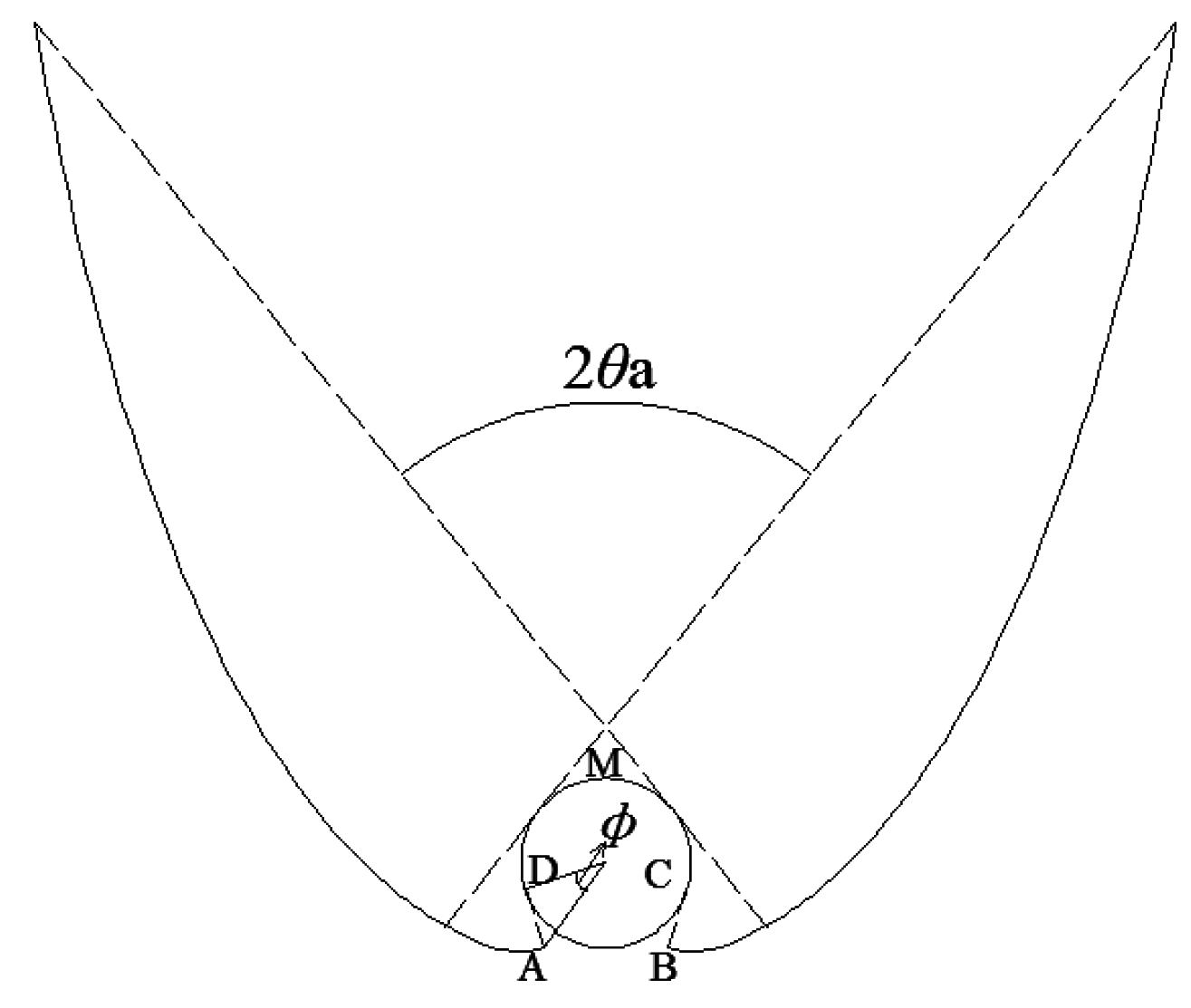
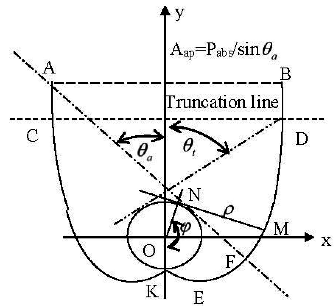
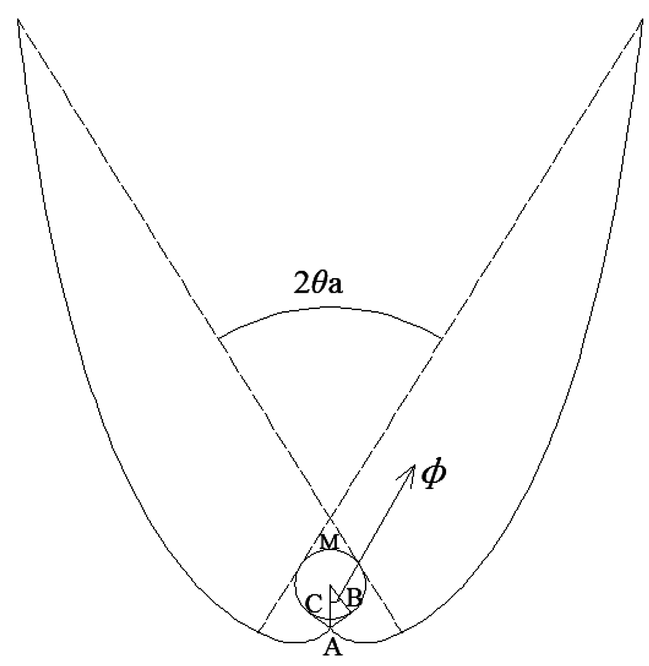
2.1. Geometry of Compound Parabolic Solar Concentrator with a Tubular Absorber

As shown in Figure 1, any point M on the reflector of CPC can be described in two parameters: φ (formed by lines from the origin O to K and N) and ρ = MN (the line tangent to the absorber tube at N). Thus, in the suggested coordinate system as shown in Figure 1, the (right) reflector of CPC constructed based on a tubular absorber is expressed by:
{ x = r   sin   φ ρ   cos   φ y = r   cos   φ ρ   sin   φ
The reflector of such CPC includes involute (0 ≤ φ ≤ 0.5π + θa) and upper reflector (0.5π + θa < φ ≤ 1.5π – θa), and one can derive the expression of ρ from the string method as follows:
ρ / r = { φ 0 φ 0.5 π + θ a 0.5 π + θ a + φ cos ( φ θ a ) 1 + sin ( φ θ a ) 0.5 π + θ a < φ 1.5 π θ a
The r in above expressions is the radius of the tubular absorber. The geometrical concentration of an ideal CPC, the ratio of aperture width (Aap) to the perimeter (Pabs,d) of absorber based on which the reflectors of CPC are constructed, is uniquely determined by its acceptance half-angle (θa) and is given by:
C i d e a l = A a p / P a b s , d = 1 / sin   θ a
and:
Aap = Cideal·Pabs,d
In practical application, the upper part of reflectors is usually truncated to save reflector materials and reduce the depth of CPC due to the lesser contribution of upper reflectors to the solar radiation concentration, and the geometrical concentration in this case can be found by substituting φ = 1.5π – θt into Equations (1) and (2) as follows:
C t = 2 x t 2 π r = cos   θ t π + sin   θ t π [ 2 π + θ a θ t + sin ( θ a + θ t ) 1 cos ( θ a + θ t ) ]
and the depth of the truncated CPC is given by:
H = π r C t c   tan   θ t + r / sin   θ t + 0.5 π r
where θt is the edge-ray angle of CPCs after truncation (Figure 1), and θt = θa for full CPCs. The last term “0.5πr” in Equation (6) is the vertical depth of lowest point ( φ = 0.5π, a point on the involutes corresponding to dy/dx = 0) of reflectors relative to the x-axis. In turn, given Ct and θa, the edge-ray angle (θt) can be obtained from Equation (5) by iterative calculations.
It must be noted that all CPCs with EST as the receiver are not ideal solar concentrators as mentioned above, and the geometrical concentration factor is the ratio of aperture width (Aap) to the perimeter of the actual solar absorber (i.e., the inner tube of EST, Pabs,a = 2πr) which might differ from Pabs,d as seen in the next section.

2.2. Design of Compound Parabolic Solar Concentrator with All-Glass Evacuated Tube as the Receiver

The EST measuring 47/58 mm in diameter of inner tube/cover tube, the one of the most common solar products in the market, is considered in this work. Based on the string method of reflector construction of CPCs [18] and geometric characteristics of EST [17], there are six symmetric CPCs most suitable for concentrating radiation on the EST as follows:
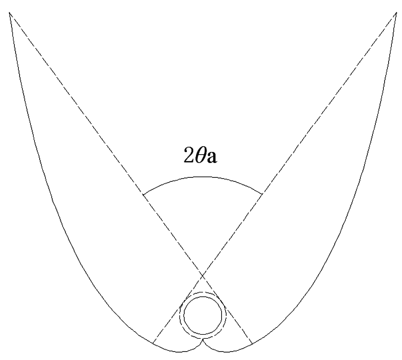
CPC-1: designed based on the cover tube (Figure 2). The geometrical concentration of full CPC-1 is given by:
C g , 1 = A a p / 2 π r = P a b s , d C i d e a l / 2 π r = R C i d e a l / r
where Pabs,d is the perimeter of cover tube (2πR) instead of 2πr because CPC-1 is designed based on the cover tube of EST. In this case, the r in Equation (1) is set to be R, and ρ in this case is given by:
ρ / R = { φ 0 φ 0.5 π + θ a 0.5 π + θ a + φ cos ( φ θ a ) 1 + sin ( φ θ a ) 0.5 π + θ a < φ 1.5 π θ a
Given θt and θa, the depth of CPC-1 is calculated by:
H = π r C t c   tan   θ t + R / sin   θ t + 0.5 π R
CPC-2: designed based on the inner tube of EST, but the EST is purposefully moved up R-r (Figure 3). The geometry concentration of full CPC-2 is Cg,2 = 1/sinθa due to Pabs,d = Pabs,a = 2πr, and the ρ in Equation (1) is given by Equation (2).
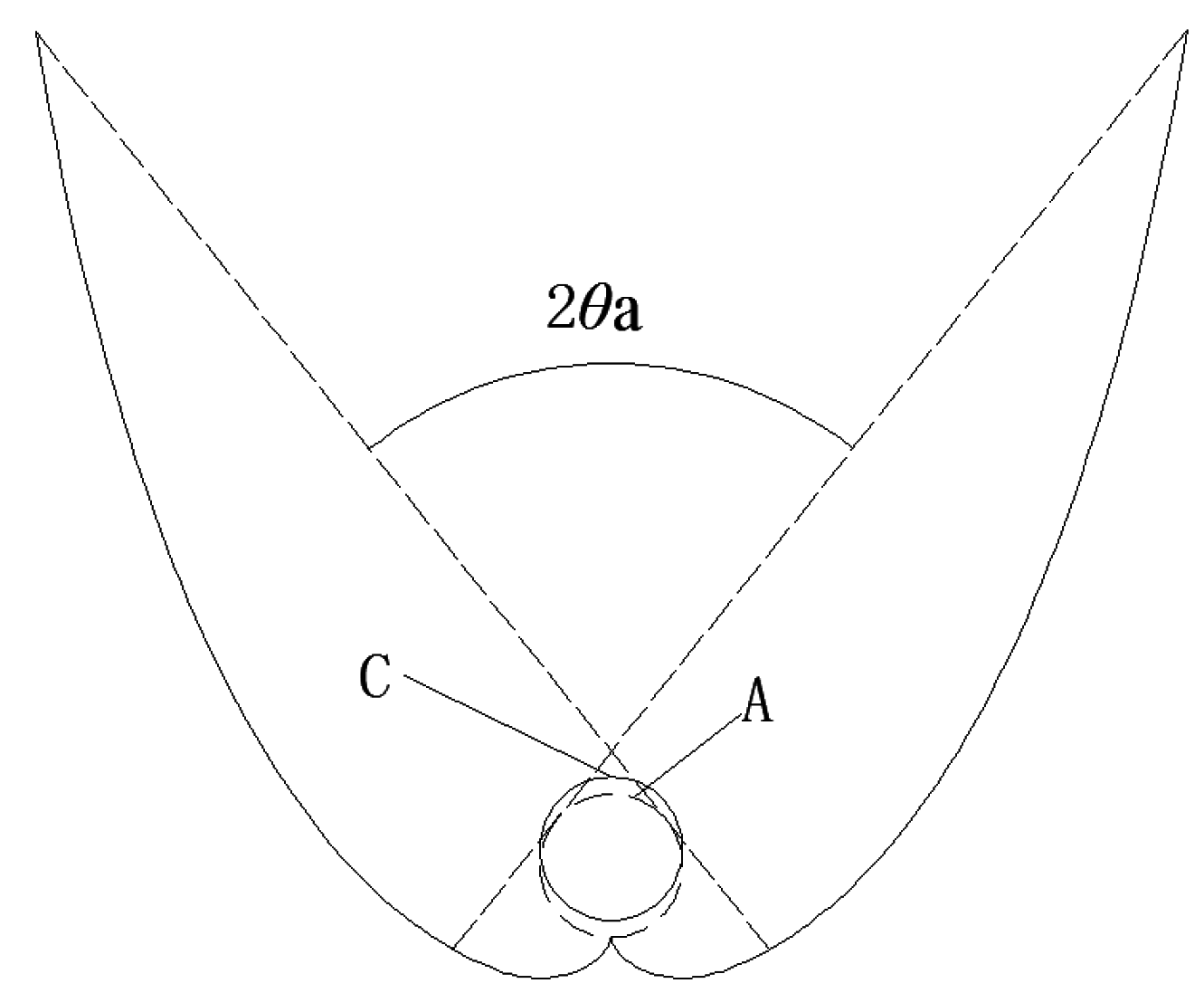
CPC-3: designed based on inner tube of EST with reflectors (involutes) near the inner tube being truncated (Figure 4). In this case, Cg,3 = 1/sinθa, but the construction of involutes starts at point B of the cover tube (Figure 4 ) with φ = ϕ, thus the ρ in Equation (1) is given by:
ρ / r = { φ ϕ φ 0.5 π + θ a 0.5 π + θ a + φ cos ( φ θ a ) 1 + sin ( φ θ a ) 0.5 π + θ a < φ 1.5 π θ a
cos ϕ = r / R
and the depth of CPC-3 is calculated from Equation (6).
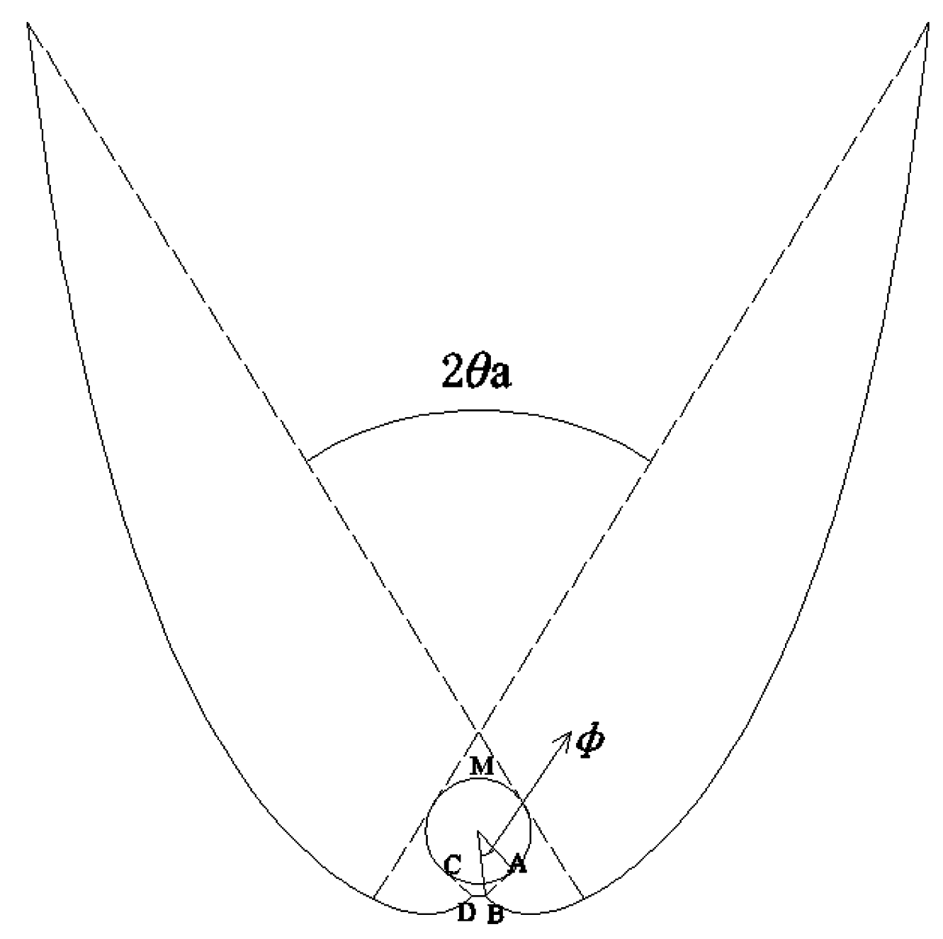
CPC-4: designed based on “ice-cream” virtual receiver. As shown in Figure 5, lines AB and AC are tangent to the inner tube of the EST, and the distance from the lowest point (A) of the “ice-cream” to the center (O) of inner tube is just equal to R in order to accommodate the vacuum space of the EST. The geometrical concentration of full CPC-4 is as follows:
C g , 4 = P i c e C i d e a l / 2 π r
where Pice = (2π – 2ϕ)r + 2AB is the circumference of “ice-cream” shaped receiver, cos ϕ = r/R (due to OA = R), and AB = R 2 r 2 . The construction of involutes in this case starts at the lowest point (A) with φ = ϕ, and the ρ in Equation (1) for φ = ϕ is AB which is obviously larger than r·ϕ. Let AB = r(ϕ + γ), thus one has:
γ = R 2 r 2 / r ϕ
And ρ in Equation (1) in this case can be derived as:
ρ / r = { φ + γ ϕ φ 0.5 π + θ a 0.5 π + θ a + φ + 2 γ cos ( φ θ a ) 1 + sin ( φ θ a ) 0.5 π + θ a < φ 1.5 π θ a
Given θt and θa, the depth of CPC-4 is calculated by:
H = π r C t c   tan   θ t + r / sin   θ t + ( 0.5 π + γ ) r
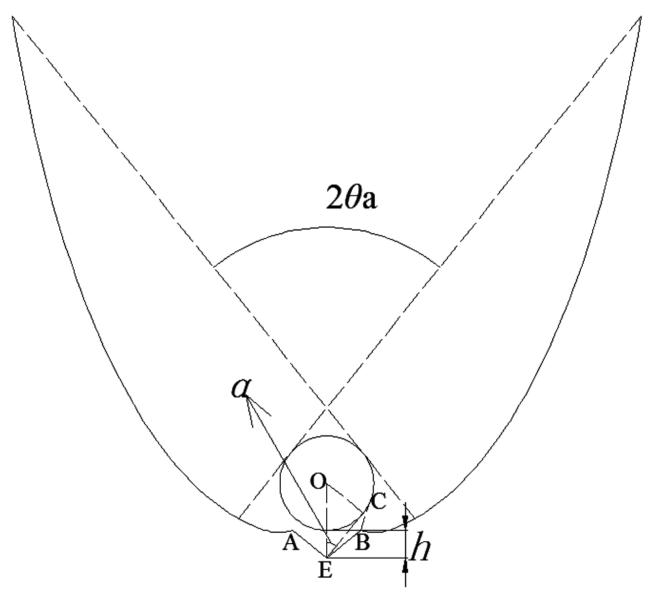
CPC-5: designed based on a fictitious “hat” absorber. As shown in Figure 6, the “hat” is constructed in such way that lines BC and AD are tangent to the inner tube of EST, the line linking A and B is also just tangent to the inner tube at the lowest point of inner tube to ensure that BC and AD can’t be seen each other, and distance from A and B to the center of inner tube is just R in order to accommodate EST. The geometrical concentration of full CPC-5 is determined by:
C g , 5 = P h a t C i d e a l / 2 π r
where Phat = (2π – 4ϕ)r + 2BC is the circumference of “hat” shaped absorber, and cosϕ = r/R. As seen from Figure 6, the involute starts at the lowest point (A) of the “hat” with φ = 2ϕ, and the ρ in Equation (1) for φ = 2ϕ is BC (BC = R 2 r 2 ) which is obviously less than 2rϕ. Let BC = r(2ϕ– ξ), thus one has:
ξ = 2 ϕ R 2 r 2 / r
The ρ in Equation (1) is expressed by:
ρ / r = { φ ξ 2 ϕ φ 0.5 π + θ a 0.5 π + θ a + φ 2 ξ cos ( φ θ a ) 1 + sin ( φ θ a ) 0.5 π + θ a < φ 1.5 π θ a
H = π r C t c   tan   θ t + r / sin   θ t + ( 0.5 π ξ ) r
CPC-6: the same as CPC-5 but with a “V” groove at the bottom (Figure 7). To avoid gap losses, the geometry of “V” groove should meet following conditions [15]:
π 2 α 2 ψ 0.5 π + α
h r c tan 2   ψ + g ( c   tan 2   ψ 1 ) / 2
where ψ is the half opening-angle of “V” groove, h the depth of “V” groove, g the vertical height of the lowest point of inner tube relative to the aperture of “V” groove and α the angle formed by line AC and the line linking A and the tube’s center. Given the size of EST, the aperture width of the “V” groove (g = 0 in the case of a single “V” groove) is equal to 2 R 2 r 2 , thus, the depth (h) is an unique parameter to determine the geometry of “V” groove, therefore one has 12.29 mm ≤ h ≤ 14.52 mm for the EST of 47/58 in diameter of inner tube/cover tube. The depth of CPC-6 (measuring from the bottom of “V” groove to aperture of CPC) is given by:
H = π r C t c   tan   θ t + r / sin   θ t + r + h
Analysis in the above shows that, given the acceptance half-angle θa, the geometric concentration factor (Cg) and depth (H) of full CPCs differ for different CPC designs (Table 1 and Table 3). In turn, given θa and Ct, the edge-ray angle (θt) of a truncated CPC differs for different CPC designs as shown in Table 2. Table 3 shows that the depth of full CPCs is very large and greatly reduced after truncation.

3. Gap Losses of Compound Parabolic Solar Concentrators

Strictly speaking, the optical loss through gaps of CPCs, defined as the ratio of radiation lost through gaps to the total radiation incident on the receiver, depend on solar incident angle (θ, a projection incident angle of solar rays on the cross-section of CPC-troughs), geometric concentration factor (Ct) and reflectivity of reflectors, therefore the optical loss through gaps of CPCs for radiation incident at any angle is hard to calculate analytically. In this exercise, the incident radiation is simply regarded as uniformly distributed over the CPC's acceptance angle. Realize, therefore, that the results for gap losses here do not pertain to a particular angle (θ), but rather are averaged over all incidence angles within the view field of full CPCs with perfect reflection on reflectors [16].
CPC-1: When isotropic radiation falls on the aperture of the CPC, the cover tube based on which reflectors of CPC-1 are constructed would be uniformly irradiated [16], but only a fraction of the radiation received by the cover tube will arrive on the inner tube, thus, optical losses through gaps formed by inner tube and cover tube can be simply calculated by:
L 1 = 1 F c - in = 1 r / R
where Fc-in = r/R is the radiation transfer shape factor from cover tube to inner tube of EST.
CPC-2: When isotropic radiation over the acceptance angle falls on the aperture of CPC-2, the tubular absorber located at position A would be uniformly irradiated, however, only a fraction of the radiation falling on the “fictitious tube” located at A would arrive on the actual tubular absorber located at C by radiation transfer, thus, gap loss in this case is as follows:
L 2 = 1 F A C = 1 2 π arccos ( R r 2 r )
where FAC is the radiation transfer shape factor from tubular absorber at A to the one at C.
CPC-3: According to the string method of construction of CPC reflectors [18], it is known that the CPC reflectors remained after the involutes near the inner tube are truncated is an ideal solar concentrator for the fictitious absorber “DCMAB” (2πr in perimeter, Figure 4). Thus, when the incident radiation is uniformly distributed over the CPC’s acceptance angle, the fictitious absorber “DCMAB” would be uniformly irradiated (the total radiation on the absorber is 2πri), however, a fraction of the radiation incident on DC and AB will be lost, therefore, the gap loss in this case is given by:
L 3 = 2 A B ( 1 F A B a b s ) i 2 π r i = tan   ϕ ϕ π
where i is the radiation on unit area of the absorber based on which reflectors of CPCs are constructed, FAB-abs = ϕ/tan ϕ is the radiative shape factor from AB to the tubular absorber (inner tube of EST).
CPC-4: When incident radiation is uniformly distributed over the CPC’s acceptance angle, the “ice-cream” shaped absorber “ACMBA” would be uniformly irradiated because reflectors of CPC-4 are constructed based on the “ice-cream” shaped absorber, however, a fraction of the radiation incident on AC and AB will be lost, therefore, the gap loss in this case is given by:
L 4 = 2 A B ( 1 F A B a b s ) i P i c e i = tan   ϕ ϕ tan   ϕ + π ϕ
CPC-5: Similarly, the gap loss of CPC-5 is given by:
L 5 = 2 A D ( 1 F A D a b s ) i P h a t i = tan   ϕ ϕ tan   ϕ + π 2 ϕ
In Equations (25)–(27), cosφ = r/R.
CPC-6: the gap loss in this case is zero due to the use of the “V” groove at the bottom of the CPC reflectors.
Analysis of the above indicates that gap losses of full CPCs averaged for all incidence angles within the acceptance angle are independent of the acceptance half-angle but dependent on the gap design of CPCs. For EST measuring 47/58 in diameter of inner tube/cover tube, the gap losses of CPC-1, CPC-2, CPC-3, CPC-4, CPC-5 and CPC-6 are L1 = 0.1897, L2 = 0.0747, L3 = 0.031, L4 = 0.03, L5 = 0.0371 and L6 = 0, respectively. Obviously, from the point of view of optical loss through gaps, CPC-6 is the optimal design, followed by CPC-4 and CPC-3, and CPC-1 is the worst design.

4. Optical Efficiency of Compound Parabolic Solar Concentrators (CPCs)

The optical efficiency of a CPC (η), termed as the ratio of radiation received by the inner tube of EST to that incident on the aperture of CPCs, is dependent on the projection incidence angle (θ) of solar rays on the cross-section of CPC-troughs. For the CPC solar collectors investigated here, optical losses include losses through gaps and those due to imperfect reflection on reflectors. Thus, losses through gaps don’t fully represent the real optical performance of such CPC. When solar rays are incident on the aperture of CPCs at any angle (θ), a part of the radiation would undergo multiple reflections before arriving on the inner tube of the EST [19]. However, for CPCs with tubular absorbers, it is very difficult to theoretically calculate the fractions of radiation that arrive on the absorber after any number of reflections. Therefore, theoretical calculations of optical efficiency are very difficult because the pathway of the solar rays to the inner tube of the EST is considerably complex. In this exercise, the ray-tracing technique was employed to analyze the optical efficiency of CPCs for radiation incident at any angle, then the radiation on the inner tube of EST of CPC collectors at any moment of a day was calculated based on η(θ) obtained from the ray-tracing analysis and θ obtained based on the solar geometry. In the subsequent theoretical analysis, the reflectivity of CPC reflectors ( ρ ) was taken to be 0.92 except with a specific indication, and the solar transmittance of the cover tube is set to be 1.
Figure 8 presents angular variations of η for full CPCs with θa = 20°. It is shown that, except for CPC-1 and CPC-2, η as a function of θ increases with the increase of incidence angle as θ < 17°, then sharply decreases. This is because a considerable fraction of the incident radiation undergoes multiple reflections before arriving on the absorber when the incidence angle (θ) is small, and the radiation lost through gaps is high in the case of θ close to the acceptance angle. Whereas for CPC-1 and CPC-2, the situation is reversed, the gap losses are high when θ is small and low when θ is large, especially for CPC-2.
Angular variations of optical efficiency of truncated CPCs are presented in Figure 9. It is shown that, for radiation within the acceptance angle (θ < θa), the optical efficiency of CPC-6 is the highest and that of CPC-1 is the lowest (Figure 8 and Figure 9), and those of CPC-4 and CPC-5 are almost identical.
However, for the case of θ > θa, the optical efficiency of CPC-5 and CPC-6 is lower than that of others due to the small edge-ray angles (Table 2). This means that, given θa and Ct, CPC-5 and CPC-6 are highly efficient to concentrate radiation on EST in the case of θ < θa but less efficient as θ > θa.
To evaluate the optical performance of six CPC designs for incident radiation over its acceptance angle, the average optical efficiency ( η ¯ ), a ratio of the radiation received by the inner tube of EST for radiation from all directions over the acceptance angle to that incident on the aperture, is introduced. Therefore, η ¯ depends on the angular distribution of solar rays over the acceptance angle, and for isotropic radiation it is expressed by:
η ¯ = θ a θ a id θ   cos   θ η ( θ ) θ a θ a id θ   cos   θ
where i is the directional intensity of radiation. Based on the angular variation of η obtained by ray-tracing analysis, the η ¯ can be numerically estimated by Equation (28).
As seen in Table 4 (in these numerical calculations, the angle step to find η ¯ is taken to be 1°), η ¯ of CPC-6 is the highest regardless whether they are truncated, followed by CPC-4 for truncated CPCs and CPC-3 for full CPCs, and η ¯ of CPC-1 is the lowest. This implies that, in the terms of η ¯ , CPC-6 is the optimal design, followed by CPC-4 for truncated CPCs and CPC-3 for full CPCs, and CPC-1 is the worst solution. Table 4 also indicates that, with the decrease of geometric concentration (Ct), η ¯ of CPCs increases, a result of the fact that radiation incident on the upper portion of CPC reflectors would undergoes multiple reflections before arriving on the absorber [19], and the average reflection number of solar rays within the CPC cavity decreases with the decrease of Ct. It must be noted that, for truncated CPCs, the η ¯ merely represents the performance of CPCs for radiation over the acceptance angle (θa) rather than the performance for radiation within θt. In the case of radiation beyond its acceptance angle, the radiation on the absorber will be so low that the desired high temperature is not achievable. Therefore to provide high temperature heat, the sun must be kept within the acceptance angle of CPCs during the operation. As seen from Table 4, given θa and Ct, η ¯ of CPC-6 is the highest, followed by CPC-4, thus, for high temperature applications, CPC-6 and CPC-4 are advisable due to high solar flux on the EST resulting from high η for radiation within the acceptance angle.

5. Annual Collectible Radiation on All-Glass Evacuated Solar Tube of CPC Collectors

Assuming that EST in CPC collectors is oriented in the east-west direction and the aperture of CPCs is tilted at β relative to the horizon, side effects of CPCs’ reflectors and radiation reflected from the ground are not considered. Thus, radiation received by unit length of EST at any moment is given by:
I = A a p I b η ( θ ) g ( θ i n ) cos θ i n + I a b s , d
where Ib is the instantaneous intensity of beam radiation; θin is the real incident angle of solar rays on CPC collectors; gin) is a control function, being 1 for cos θin ≥ 0, otherwise zero; Iabs,d is the sky diffuse radiation received by EST of CPCs and estimated by:
I a b s , d = A a p θ x θ t i η ( θ ) cos θ d θ
where θx = Min(0.5π – β, θt); i is the directional intensity of sky diffuse radiation on the cross-section of EST, and i = 0.5Id for isotropic sky diffuse radiation [19,20]; Id is the sky diffuse radiation on the horizon. Thus, Equation (30) is rewritten as:
I a b s , d = 0.5 I d A a p [ 0 θ t η ( θ ) cos θ d θ + 0 θ x η ( θ ) cos θ d θ ] = 0.5 I d A a p ( C d 1 + C d 2 )
and   C d 1 = 0 θ t η ( θ ) cos θ d θ
C d 2 = 0 θ x η ( θ ) cos θ d θ
Given θa and Ct, θt of CPCs can be obtained based on the equation of CPC reflectors, then Cd1 and Cd2 can be obtained based the method aforementioned. At any moment of a day, θin and θ in Equation (29) can be calculated from solar geometry [15]. Knowing the time variation of Ib in a day, the daily radiation on EST is obtained by integrating Equation (29) over the daytime [17,19]:
H d a y = A a p t 0 t 0 η ( θ ) g ( θ i n ) I b cos θ i n d t + 0.5 H d A a p ( C d 1 + C d 2 )
and the annual radiation on EST (Sa) is estimated by summing Hday in all days of a year. Given the monthly radiation on the horizon, the monthly average daily sky diffuse radiation, Hd, time variation of Ib in a day can be found [21].
In the following analysis, the angle step to find η(θ) is taken to be 1°, the time step for calculating Hday is set to be 1 min, the η(θ) of CPCs at any moment is estimated based on θ at the moment and a linear extrapolation technique. The monthly horizontal radiation used in this work was taken from the book edited by Chen [22].
To compare the performance of six CPCs in terms of Sa, two cases with β being yearly fixed (1T-CPC) and yearly adjusted four times at three tilts (3T-CPC), are considered. For 1T-CPCs, β = λ, θa = 26° [23], whereas for 3T-CPCs, β = λ during periods of 23 days around both equinoxes, and adjusted to λ + 23 and λ – 23 in winters and summers, respectively [19,20]. Five sites with typical climatic conditions (Beijing: dry land with abundant solar resources; Shanghai, a site climatically characterized by rainy winters and sunny summers; Lhasa: a highland with extremely abundant solar resources; Chongqing: a site with poor solar resources; Kunming, a site climatically characterized by sunny winters and rainy summers) are selected as the representatives for the analysis.

5.1. Annual Collectible Radiation on All-Glass Evacuated Solar Tube of 1T-CPCs

Table 5 presents the annual radiation on EST of 1T-CPCs. It is seen that, regardless of whether full CPCs or truncated CPCs are used, the annual radiation collected by CPC-4 is always highest. For full CPCs with identical θa, the annual radiation collected by CPC-5 is the lowest; whereas for truncated CPCs with identical θa and Ct, the annual radiation by the CPC-1 is the lowest (Figure 10 and Figure 11).

5.2. Annual Collectible Radiation on All-Glass Evacuated Solar Tube of 3T-CPCs

Table 6 lists the annual collectible radiation on EST of 3T-CPCs. It is seen that, for full CPCs with identical θa, the CPC-1 yearly concentrates the most solar radiation, followed by CPC-4 and CPC-3, and the CPC-5 concentrates the least radiation. The effect of the reflector’s reflectivity on the Sa of full CPCs is presented in Figure 12 and the same situation as seen in Table 5 was found. This is because, given θa, the geometric concentration factor of full CPC-1 is the largest and that of full CPC-5/6 is the smallest (Table 1). It is also seen that, for truncated CPCs with identical θa and Ct, the annual radiation collected by CPC-4 is the highest, followed by CPC-3, and the CPC-1 annually collected least radiation for the case of ρ > 0.85 otherwise CPC-5 annually collects the least radiation (Figure 13). Effect of geometric concentration factor on Sa of truncated 3T-CPCs is shown in Figure 14, and it is seen that the Sa linearly increases with the increase of Ct, the CPC-4 annually concentrates most radiation and CPC-1 annually collects the least radiation.
In practical applications, CPCs are usually truncated due to the lesser contribution of the upper portion of reflectors to radiation collection [24], therefore, among the six CPCs investigated in this work, CPC-4 is the optimal design for concentrating solar radiation on the EST and CPC-1 is the most inferior solution in terms of annual collectible radiation.

6. Conclusions

CPC reflectors always extend their pathways to the absorber based on which the CPC is designed, but for all-glass EST, the tubular absorber is enclosed within the cover tube, thus, gaps between reflectors and inner tube are required for allowing vacuum space. According to the design principle of ideal solar concentrators and the geometric characteristics of the EST, there are six CPCs most suitable to concentrate solar radiation on an EST.
From the point of view of the optical loss through gaps of CPCs, CPC-6, designed based on a fictitious “hat” shaped absorber with a “V” groove at the bottom, is the optimal design due to the absence of gap loss, followed by CPC-4, designed based on a fictitious “ice-cream” shaped receiver, and CPC-1, designed based on the cover tube, has the maximum gap loss and thus is the most inferior design.
From the point of view of optical efficiency averaged for radiation over the acceptance angle, CPC-6 is the optimal design regardless whether CPCs are truncated or not, followed by CPC-4 for truncated CPCs and CPC-3 for full CPCs, and CPC-1 is the most inferior solution. It is also found that, for truncated CPCs, CPC-6 is the most efficient for the radiation within the acceptance angle (θ < θa) but the least efficient when θ > θa as compared to other designs. This means that, for high temperature applications, CPC-6 and CPC-4 are advisable due to the high solar flux on the EST resulting from the high optical efficiency for radiation within the acceptance angle.
From the point of view of annual collectible radiation on EST of CPCs, in the case where the tilt-angle of CPCs’ aperture is yearly fixed, CPC-4, regardless whether it is truncated, annually collects the most radiation and thus is an optimal solution; for full CPCs, CPC-5 is the worst solution, and for truncated CPCs, CPC-1 is the worst design. In the case of tilt-angle of CPCs’ aperture being yearly adjusted four times at three tilts, for full CPCs with given θa, CPC-1 concentrates the most radiation due to its largest geometric concentration, and CPC-5 collects the least radiation; whereas for truncated CPCs with identical θa and Ct, CPC-4 is the best solution, and CPC-1 is the inferior solution. In practical applications, CPCs are usually truncated to save reflector materials and reduce the depth of CPCs due to the lesser contribution of upper reflectors to radiation concentration, therefore, it is concluded that CPC-4 is the optimal design, and CPC-1 is the worst solution in terms of annual collectible radiation on the EST.

Acknowledgments

This work is partial fulfillment of the funded research program No.51466016, financially supported by Natural Science Foundation of China.

Author Contributions

Runsheng Tang is sponsor of the work; Qiang Wang is responsible for theoretical analysis of optical loss through gases of CPCs and theoretical calculation of annual solar collectible radiation; Jinfu Wang, a student for Master program, is responsible for the ray-tracing analysis.

Conflicts of Interest

The authors declare no conflict of interest.

Nomenclatures

Aaparea of CPCs’ aperture, m2
Cggeometric concentration of full CPCs, dimensionless
Cidealgeometric concentration of ideal CPCs (1/sin θ a ), dimensionless
Ctgeometric concentration of truncated CPCs, dimensionless
Fa-bradiative shape factor from surface a to surface b, dimensionless
Hdepth of CPC, mm
Hdaydaily radiation on unit length of solar tubes, MJ/m
Hddaily sky diffuse radiation on the horizon, J/m2
hdepth of V-groove, mm
Iinstantaneous radiation intensity, W/m2
idirectional intensity of sky diffuse radiation, W/m2·rad
Pabs,dperimeter of absorber based on which CPC is designed, mm
Pabs,dperimeter of actual absorber of CPC with EST (2 π r ), mm
Rradius of the cover tube, mm
rradius of the inner tube, mm
Saannual collectible radiation on solar tubes, MJ/m
tsolar time, s

Greek Letters

β tilt-angle of the aperture of CPCs from the horizon, degree
λ site latitude, degree
ϕ angle given by cos ϕ = r R , radian
φ the angle used to describe the coordinate of any point on reflectors of CPCs, radian
η ( θ ) optical efficiency factor, dimensionless
θ projection incident angle of solar rays on the cross-section of CPC-trough, radian
θ a acceptance half-angle of CPCs, degree
θ i n real incidence angle of solar rays on the aperture of CPCs, radian
θ t edge-ray angle of truncated CPCs, degree
ρ reflectivity of reflectors, dimensionless; a parameter to describe coordinates of points on reflectors
ψOpening angle of “V” groove, radian

Subscripts

absabsorber
apaperture of CPCs
bbeam radiation
dsky diffuse radiation
daydaily solar gain

References

  1. Xiao, C.; Luo, H.; Tang, R.; Zhong, H. Solar thermal utilization in China. Renew. Energy 2004, 29, 1549–1556. [Google Scholar] [CrossRef]
  2. Li, Z.; Zhong, H.; Tang, R.; Liu, T.; Gao, W.; Zhang, Y. Experimental investigation on solar drying of salted greengages. Renew. Energy 2006, 31, 837–847. [Google Scholar] [CrossRef]
  3. Tang, R.; Yang, Y.; Gao, W. Comparative studies on thermal performance of water-in-glass evacuated tube solar heaters with different collector tilt-angles. Sol. Energy 2011, 85, 1381–1387. [Google Scholar] [CrossRef]
  4. Rabl, A. Optical and thermal properties of compound parabolic concentrators. Sol. Energy 1976, 18, 497–510. [Google Scholar] [CrossRef]
  5. Rabl, A.; Ogallagher, J.; Winston, R. Design and test of non-evacuated solar collectors with compound parabolic concentrators. Sol. Energy 1980, 25, 335–351. [Google Scholar] [CrossRef]
  6. Grass, C.; Schoelkopf, M.; Staudacher, L.; Hacker, Z. Comparison of the optics of non-tracking and novel types of tracking solar thermal collectors for process heat applications up to 300 °C. Sol. Energy 2004, 76, 207–215. [Google Scholar] [CrossRef]
  7. Baum, H.P.; Gordon, J.M. Geometric characteristics of ideal non-imaging (CPC) solar collectors with cylindrical absorber. Sol. Energy 1984, 33, 455–458. [Google Scholar] [CrossRef]
  8. Mill, D.R.; Bassett, I.M.; Derrick, G.H. Relative cost-effectiveness of CPC reflector designs suitable for evacuated absorber tube solar collectors. Sol. Energy 1986, 36, 199–206. [Google Scholar] [CrossRef]
  9. Mill, D.R.; Monger, A.; Morrison, G.L. Comparison of fixed asymmetrical and symmetrical reflectors for evacuated tube solar receivers. Sol. Energy 1994, 53, 91–104. [Google Scholar] [CrossRef]
  10. Buttinger, F.; Beikircher, T.; Proll, M.; Scholkopf, M. Development of a new flat stationary evacuated CPC-collector for process heat applications. Sol. Energy 2010, 84, 1166–1174. [Google Scholar] [CrossRef]
  11. Oommen, R.; Jayaraman, S. Development and performance analysis of compound parabolic solar concentrators with reduced gap losses—Oversized reflectors. Energy Convers. Manag. 2001, 42, 1379–1399. [Google Scholar] [CrossRef]
  12. Oommen, R.; Jayaraman, S. Development and performance analysis of compound parabolic solar concentrators with reduced gap losses—“V” groove reflector. Renew. Energy 2002, 27, 259–275. [Google Scholar] [CrossRef]
  13. Tang, R.; Yang, Y. Nocturnal reverse flow in water-in-glass evacuated tube solar water heaters. Energy Convers. Manag. 2014, 80, 173–177. [Google Scholar] [CrossRef]
  14. Zhang, Q.Z.; Zhao, K.; Zhang, B.C.; Wang, L.F.; Shen, Z.L.; Zhou, Z.J.; Lu, D.Q.; Xie, D.L.; Li, B.F. New cermet solar coatings for solar thermal electricity applications. Sol. Energy 1998, 64, 109–114. [Google Scholar] [CrossRef]
  15. Rabl, A. Active Solar Collectors and Their Applications; Oxford University Press: Oxford, UK, 1985. [Google Scholar]
  16. Rabl, A.; Goodman, N.B.; Winston, R. Practical design considerations for CPC solar collectors. Sol. Energy 1979, 22, 373–381. [Google Scholar] [CrossRef]
  17. Xu, R.; Zhang, Q.; Tang, R. Optical performance comparison of six ACPCs for concentrating radiation on all-glass evacuated solar tubes. Adv. Mater. Res. 2015, 1092–1093, 52–58. [Google Scholar] [CrossRef]
  18. Gordon, J.M. Simple string construction method for tailored edge-ray concentrators in maximum-flux solar energy collectors. Sol. Energy 1996, 56, 279–284. [Google Scholar] [CrossRef]
  19. Tang, R.; Wang, J. A note on multiple reflections of radiation within CPCs and its effect on calculations of energy collection. Renew. Energy 2013, 57, 490–496. [Google Scholar] [CrossRef]
  20. Tang, R.; Liu, X. Optical performance and design optimization of V-trough concentrators for photovoltaic applications. Sol. Energy 2011, 85, 2154–2166. [Google Scholar] [CrossRef]
  21. Collares-Pereira, M.; Rabl, A. The average distribution of solar radiation: correlation between diffuse and hemispherical and between hourly and daily insolation values. Sol. Energy 1979, 22, 155–164. [Google Scholar] [CrossRef]
  22. Chen, Z.Y. The Climatic Summarization of Yunnan; Weather Publishing House: Beijing, China, 2001. [Google Scholar]
  23. Tang, R.; Wu, M.; Yu, Y.; Li, M. Optical performance of fixed east-west aligned CPCs used in China. Renew. Energy 2010, 35, 1837–1841. [Google Scholar] [CrossRef]
  24. Carvalho, M.J.; Collares-Pereira, M.; Gordon, J.M.; Ranl, A. Truncation of CPC solar collectors and its effect on energy collection. Sol. Energy 1985, 35, 393–399. [Google Scholar] [CrossRef]
Figure 1. Geometry of a tubular absorber ideal solar concentrator (not to scale).
Energies 09 00795 g001
Figure 2. CPC-1, designed based on the cover tube of evacuated solar tube (EST).
Energies 09 00795 g002
Figure 3. CPC-2, designed based on inner tube with the EST purposely being moved up R-r.
Energies 09 00795 g003
Figure 4. CPC-3, designed based on inner tube of EST with the involutes near the inner tube being truncated.
Energies 09 00795 g004
Figure 5. CPC-4, designed based on an “ice-cream” absorber.
Energies 09 00795 g005
Figure 6. CPC-5, designed based on “hat” absorber.
Energies 09 00795 g006
Figure 7. CPC-6, the same as CPC-5 but with a “V” groove at the bottom.
Energies 09 00795 g007
Figure 8. Angular variations of optical efficiency of full CPCs with θa = 20°.
Energies 09 00795 g008
Figure 9. As in Figure 8 but for truncated CPCs with θa = 20° and Ct = 2.
Energies 09 00795 g009
Figure 10. Effects of reflectivity on the annual collectible radiation on EST of full 1T-CPCs.
Energies 09 00795 g010
Figure 11. As in Figure 10 but for truncated 1T-CPCs.
Energies 09 00795 g011
Figure 12. As in Figure 10 but for full 3T-CPCs.
Energies 09 00795 g012
Figure 13. As in Figure 10 but for truncated 3T-CPCs.
Energies 09 00795 g013
Figure 14. Effects of geometric concentration on Sa of truncated 3T-CPCs.
Energies 09 00795 g014
Table 1. Geometric concentration factors of full compound parabolic solar concentrators.
θaCPC-1CPC-2CPC-3CPC-4CPC-5CPC-6
20°3.6082.9242.9243.0142.4312.431
26°2.8152.2812.2812.3511.8971.897
Table 2. Edge-ray angle of truncated CPCs with θa = 20°.
CtCPC-1CPC-2CPC-3CPC-4CPC-5CPC-6
Ct = 2.079.3°61.4°61.4°64.1°44.8°44.8°
Ct = 2.463.8°45.3°45.3°48.1°24.7°24.7°
Table 3. Depth of CPCs with θa = 20°.
Size of CPCCPC-1CPC-2CPC-3CPC-4CPC-5CPC-6
Ct = 2.0103.1144.2144.2137.0206.7218.0 *
Ct = 2.4165.1245.4245.4229.7466.3477.6 *
Full CPCs862.2698.7698.7701.0686.3697.6 *
Note: * h is set to be 12.29 mm in these calculations.
Table 4. Average optical efficiency η ¯ of CPCs with θ a = 20 o .
Size of CPCsCPC-1CPC-2CPC-3CPC-4CPC-5CPC-6
Ct = 2.00.743260.862120.876570.879670.864770.89542
Ct = 2.10.741800.858690.873070.875920.861460.89326
Ct = 2.20.740050.855740.868920.871730.858830.89061
Ct = 2.30.739400.852880.864440.866570.856600.88750
Ct = 2.40.738410.849330.861250.861790.852630.88292
Full CPC0.711100.834240.843790.832050.846750.87611
Table 5. Annual radiation on EST of 1T-CPCs with θa = 26° and ρ = 0.92 (MJ/m).
SiteFull 1T-CPCsTruncated 1T-CPCs (Ct = 1.8)
CPC-1CPC-2CPC-3CPC-4CPC-5CPC-6CPC-1CPC-2CPC-3CPC-4CPC-5CPC-6
Beijing132212521289132710751106101311611151116610691101
Shanghai10049499771007816838800899888902813836
Lhasa205119431999206016691715155817891773179716561704
Chongqing728683705726589606597659649659588605
Kunming129312191256129410481078101711431130114510421073
Table 6. Annual radiation on EST of 3T-CPCs with θa = 20° and ρ = 0.92 (MJ/m).
SiteFull 3T-CPCsTruncated 3T-CPCs (Ct = 2)
CPC-1CPC-2CPC-3CPC-4CPC-5CPC-6CPC-1CPC-2CPC-3CPC-4CPC-5CPC-6
Beijing198117261818187115191597132813841426144213411398
Shanghai14461265133113691112116710081046107110859941036
Lhasa315827432894297924172544207621682243226621232214
Chongqing996875920946768805723746759770696724
Kunming189116501739178914521526129513451383139912911346

