1. Introduction
Recently, due to the widespread applications of distributed generations, adjustable speed drives, uncontrolled AC/DC rectifiers, and other nonlinear loads, the harmonic pollution in power systems is becoming increasingly more serious. The passive power filter (PPF) and active power filter (APF) are the two common solutions applied to mitigate these harmonics [
1,
2]. PPFs have the advantages of low-cost and high-efficiency. However, they also have some inherent drawbacks. Their compensation characteristics are strongly influenced by supply impedance and they are highly susceptible to series and parallel resonances with the supply and load impedance. The APFs, which are based on power electronics, can overcome the above drawbacks of PPFs [
3,
4]. Additionally, APFs are more flexible and efficient compared with PPFs. However, pure APFs usually require a PWM inverter with a large kilovolt ampere (KVA) rating. Thus, they do not constitute a cost-effective harmonic filtering solution for nonlinear loads above 500–1000 kW [
5,
6]. To address this issue, hybrid active power filters (HAPF) have been developed, which are composed of a small rated APF and a PPF in different configurations. Among the various viable hybrid active filter topologies, parallel hybrid active filters present a cost-effective solution for harmonic filtering and reactive power compensation of high power nonlinear industrial loads, due to the small rating of the active filter (2%–3%) of the load KVA rating [
6]. Thus, they have attracted increasing attention [
7,
8,
9,
10,
11].
Among various control strategies, repetitive control, as a kind of control method based on the internal model principle, can accurately track the periodic signal or reject periodic interference. Hence it is widely used in the harmonic compensation scheme for active filters [
12,
13,
14,
15]. The traditional repetitive control technique can generate infinite gains at all the integer multiples of the fundamental frequency, including the odd, even harmonics, and dc component. However, in most cases, the introduction of high gain for all frequencies is not necessary, as it could waste control effort and reduce the system robustness without improving system performance, even amplify irrelevant signals, and reinject distortions to systems [
16]. Moreover, the control action of the traditional repetitive controller is postponed by one fundamental period (
T0), hence the transient performance is poorer. To improve the drawbacks above, and considering the fact that even harmonic components do not regularly appear in power systems, literature references [
16,
17] propose a repetitive control scheme aimed at compensating only the odd harmonics. This uses a negative feedback array instead of the usual positive feedback in the traditional repetitive controller. Meanwhile, the delay time of the control action is reduced to
T0/2. As a sequence, the control performance is improved and the convergence rate is enhanced. Furthermore, among the odd harmonics, the group of
harmonic components in the electrical industry are dominant due to the wide use of uncontrolled rectifiers and six-pulse converters. Thus, many improved repetitive control schemes aiming at compensating
harmonics have been developed [
18,
19,
20]. For instance, in [
18] a repetitive control scheme based on the feedback array of two delay lines plus a feed forward path is presented, which can only compensate
harmonics and reduce the delay time to T
0/3; In [
19], the authors propose a
repetitive control scheme in there-phase synchronous reference frame (SRF). It has an advantage of T
0/6 delay time. However, it needs complex coordinate transformation and much more calculation in both the positive-rotating and negative-rotating SRFs.
Considering three-phase power systems, harmonics of the same frequency can be decomposed into positive sequence, negative sequence, and zero sequence. Generally speaking, a normal balanced three-phase system mainly contains 6k + 1 harmonics (such as −5, +7, −11, +13), and rarely contains 6k − 1 harmonics (such as +5, −7, +11, −13). For this reason, this paper proposes a repetitive control scheme aimed at compensating the 6k + 1 harmonics implemented in a three-phase stationary reference frame with T0/6 delay time in order that the transient performance is further improved. The 6k + 1 repetitive controller is expressed with complex-vector notation, so that the dual-input/dual-output control system (in the reference frame) can be simplified into one single-input/single-output system. Meanwhile, the general design method of the Lk + M repetitive controller is also introduced, with which a repetitive controller aimed at compensating Lk + M harmonics can be easily deduced. Moreover, taking the transformerless parallel hybrid active filter as the controlled object, a harmonic compensating control system based on the proposed repetitive control scheme is presented. Finally, the experimental results validate the effectiveness of the repetitive control scheme.
3. System Control
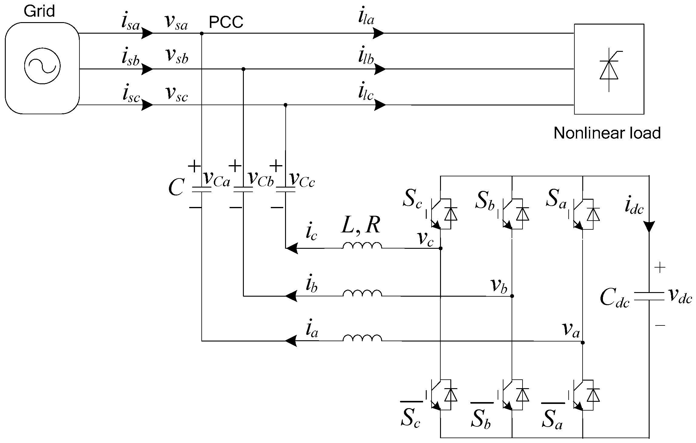
According to (1) and (2), it can be inferred that the state equation of the output current
is a second-order differential equation. If the output current control is implemented in a dq synchronous reference frame, it needs to sample and feedback the AC capacitor voltage
to achieve decoupling control between the d-axis and q-axis. Therefore, in this paper, the output current control is implemented in the
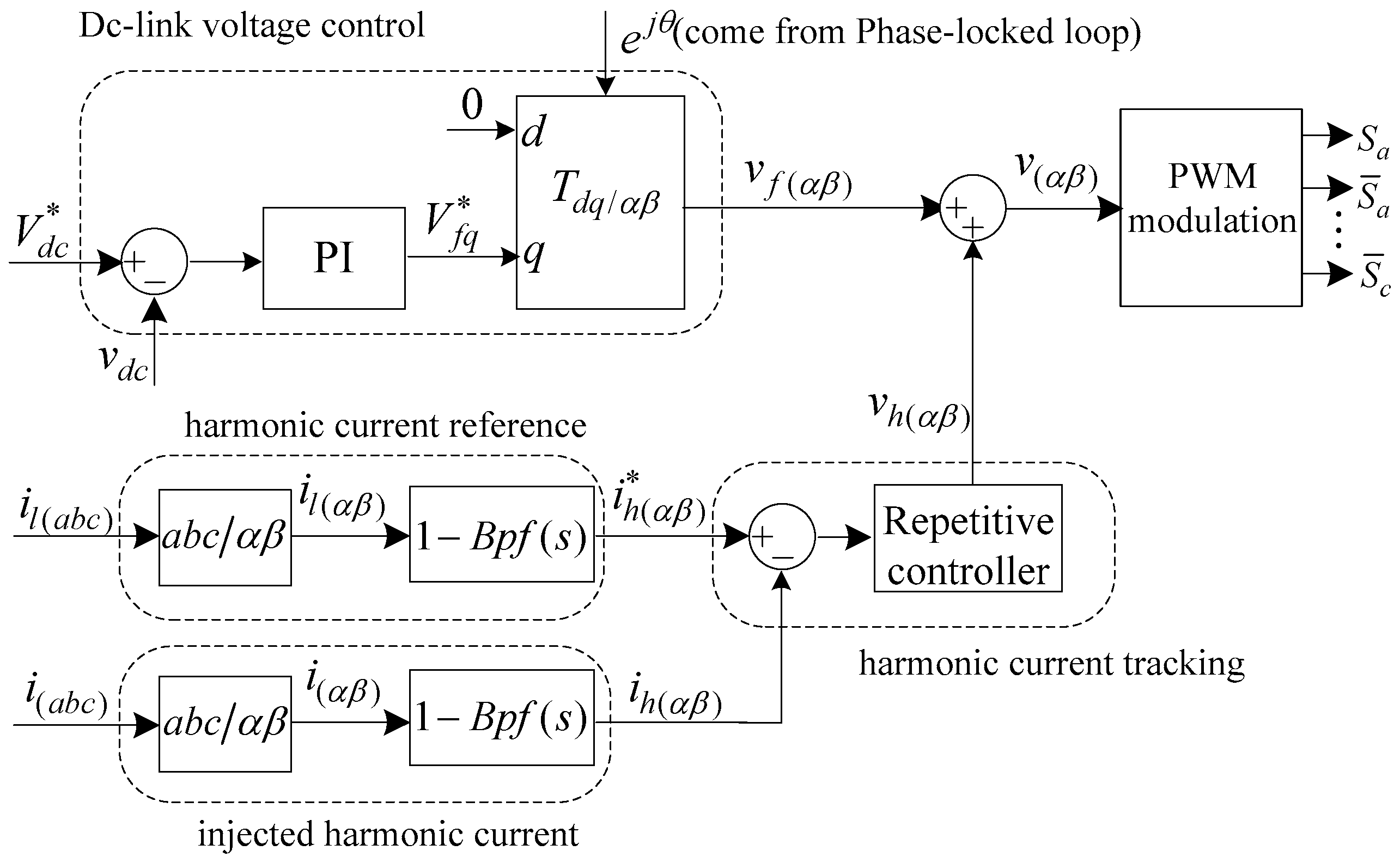
stationary frame, which has the advantages of no requirements for complex decoupling control and AC capacitor voltage sampling. The overall system control diagram is shown in
Figure 2, it is mainly composed of dc-link voltage control and harmonic current tacking control. In this figure,
Bpf(
s) is a band-pass filter to extract the fundamental frequency component of the input signal, and its expression is given by
where
is the grid frequency;
is the control coefficient of passband width and
.
3.1. DC-Link Voltage Stabilization Method
Assuming that the VSI does not provide reactive power compensation for the load and only absorbs active power from the grid to maintain its power loss then according to the power conservation principle, we have
where
is the active power absorbed from the grid,
is the power of the dc-link capacitor, and
is the power loss of the inverter. It can be inferred from (6) that if
is regarded as a disturbance,
could be controlled by adjusting
. In the dq synchronous reference frame (grid voltage orientation), the active power
and reactive power
absorbed by VSI can be given by
where X denotes the fundamental frequency impedance of the LC filter;
is the d-axis component of the grid voltage (
);
,
are the d-axis and q-axis components of the VSI output fundamental voltage, respectively.
It can be inferred from (7) that
is only regulated by
. Generally,
is small. Thus,
could be achieved when
is set to 0. Thus, the dc-link voltage regulator can be designed as (8), and the corresponding bode diagram is shown in
Figure 2.
where
is the rated value of the dc-link voltage;
,
are the parameters of the PI controller.
3.2. Harmonic Current Tracking Control
Harmonic current tracking control is the important part of system control, which contributes directly to the performance of harmonic compensating. The block diagram of current control is shown in
Figure 2. Considering the case that the three-phase load current mainly contains 6
k + 1 harmonics, this paper presents a 6
k + 1 repetitive control scheme to compensate these harmonics. The detailed theoretical derivation, analysis, and design of the proposed 6
k + 1 repetitive controller is given in the next section.
4. Repetitive Control Scheme (6k + 1)
4.1. Internal Model of 6k + 1 Repetitive Controller
Firstly, the internal model of the well-known traditional repetitive controller is given by
where
is the periodic time delay unit, and
T0 is the fundamental period, i.e.,
.
By setting the denominator
in (9) equal to zero, the following can be obtained
where
is the pole of (9). Seen from (10), it is clear that the traditional repetitive controller has an infinite number of poles located at
, which is the reason that the traditional repetitive controller has resonant peaks at every integral multiple of fundamental frequency
.
In order to make a repetitive controller with poles only located at a selected group of harmonic frequencies, a new internal model needs to be structured. Assume the order h of these harmonics meets the rule:
where
L,
M are intergers, and L is not equal to zero.
Then, the poles of the new internal model should be located at
Moreover, to enhance the frequency selectivity, an infinite number of zeros of the new internal model that are located in the midpoints between two consecutive poles are introduced as
These zeros bring another benefit of allowing bigger gains with improved performance.
In order to satisfy (12) and (13), the general internal model for
harmonics can be structured as
After the substitution of
L = 6 and
M = 1 in (14), the 6
k + 1 internal model is given by
Comparing (15) with the traditional internal model given by (9), it can be found that the delay time of 6
k + 1 internal model is reduced to
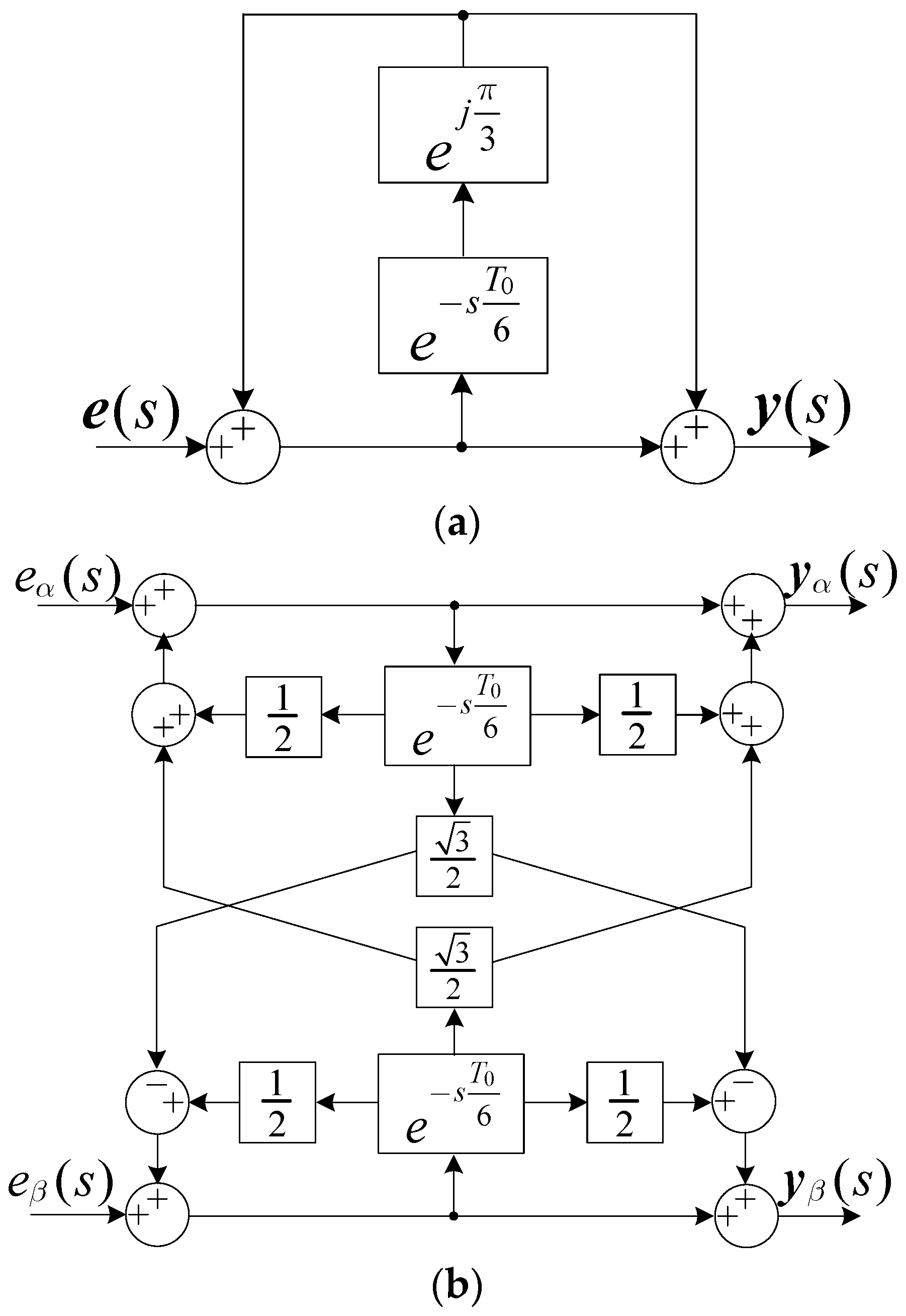
T0/6, which means a much faster dynamic response. What is more, it should be noted that the 6
k + 1 internal model is expressed using the complex-vector notation, as it contains the complex coefficient
. As a consequence, the input signal of
(s) is required to be a complex vector. The block of the proposed 6
k + 1 internal model is shown in
Figure 3.
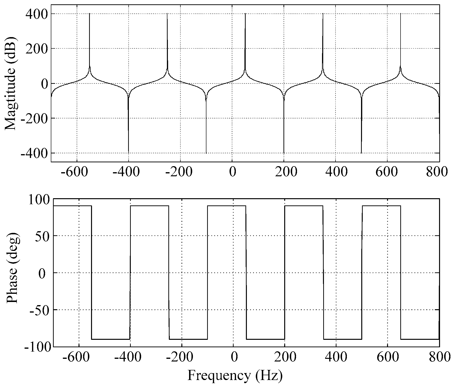
Assuming that the fundamental frequency
f0 = 50 Hz, i.e., T
0 = 0.02 s, the bode plot of the 6
k + 1 repetitive controller internal model is shown in
Figure 4. As expected, the amplitude-frequency response curve shows that the 6
k + 1 internal model has resonant peaks that are located at frequency multiples 6
k + 1 of 50 Hz (50, −250, 350, −550, 650 Hz...), and has notches that are located at frequency multiples 6
k + 4 of 50 Hz (−100, 200, −400, 500 Hz...). The phase-frequency response curve shows the phase shift is bound between 90° and −90°, and zero at the peaks and notches.
4.2. Fractional Delay Compensation
In a practical application, the implementation of the repetitive control scheme is usually performed in the digital form. Using the transformation
, (15) can be discretized and its expression in discrete time domain is given by
where
Ts is the sampling period, and
(the number of samples per fundamental period).
In most cases, the sampling frequency () is a fixed rate (e.g., 10 kHz, 12.8 kHz, 20 kHz), and the grid frequency detected by PLL is variable in a certain range (e.g., 49–51 Hz). Thus, is usually non-integer.
Let
where
D and
d are the integral and fractional parts of
, respectively.
In a common implementation, is approximately treated as and performed by reserving D memory locations, with the fractional order part neglected. However, this will cause the resonant peaks to deviate from the harmonic frequencies. As a consequence, the harmonic compensation performance could be degraded.
To address this problem, fractional delay (FD) filters have been used as approximations of
. The magnitude-frequency and phase-frequency characteristics of
can be given by
Thus, it requires that FD filters should have a unit gain and linear phase in the low-middle frequencies, and achieve a high attenuation rate in the high frequencies to enhance the system stability.
In the condition of
(i.e.,
), with the use of the Taylor expansion,
can be expressed as
Specifically, choosing the first-order Taylor expansion of
as a FD filter, that is
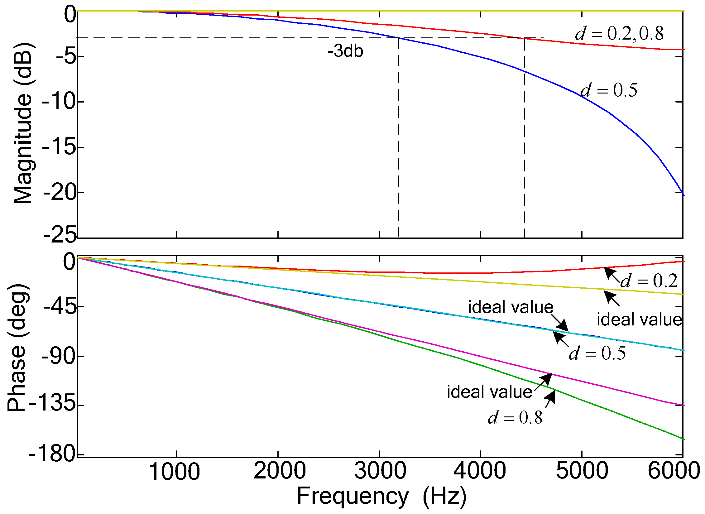
Figure 5 shows the bode plot of
, with
,
d = 0.2, 0.5, and 0.8, respectively. It can be seen that
has a low-pass filter nature. At low frequencies,
has a good linear phase approximating to the ideal value. However, the main disadvantages of
are that the cutoff frequency is too high (greater than 3000 Hz), and it changes with the value of
d. Only when
d = 0.5, does
achieve the lowest cutoff frequency and the best linear phase.
To overcome the above issue, this paper presents a FD filter
by cascading
Fd(z) with a zero-phase digital low-pass filter, i.e.,
where
is the zero-phase digital low-pass filter used to lower the cut-off frequency and increase the attenuation rate at high frequencies. Its expression is given as
where
and
;
n is the order of filter.
Although
is non-causal, the time delay term
makes it applicable. After the fractional delay compensation, (16) should be revised as
4.3. Design of 6k + 1 Repetitive Controller
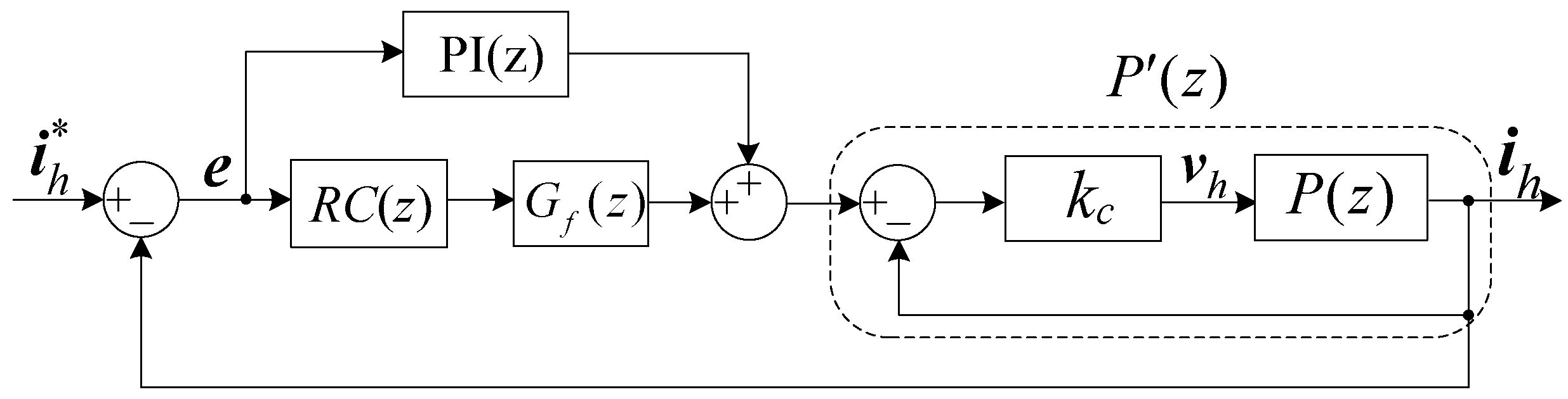
Figure 6 shows the block diagram of the harmonic current tracking control. This paper adopts a plug-in repetitive controller structure in the control loop, where the PI controller is used to enhance the stability and improve dynamic response, and the repetitive controller is used to eliminate the steady-state error.
In
Figure 6,
P(z) is the plant of the current control. According to (1) and (2), its expression in continuous domain can be obtained as
Obviously,
P(s) is a second-order system. To modify the characteristic of
P(s), a method of output current status feedback is used. According to
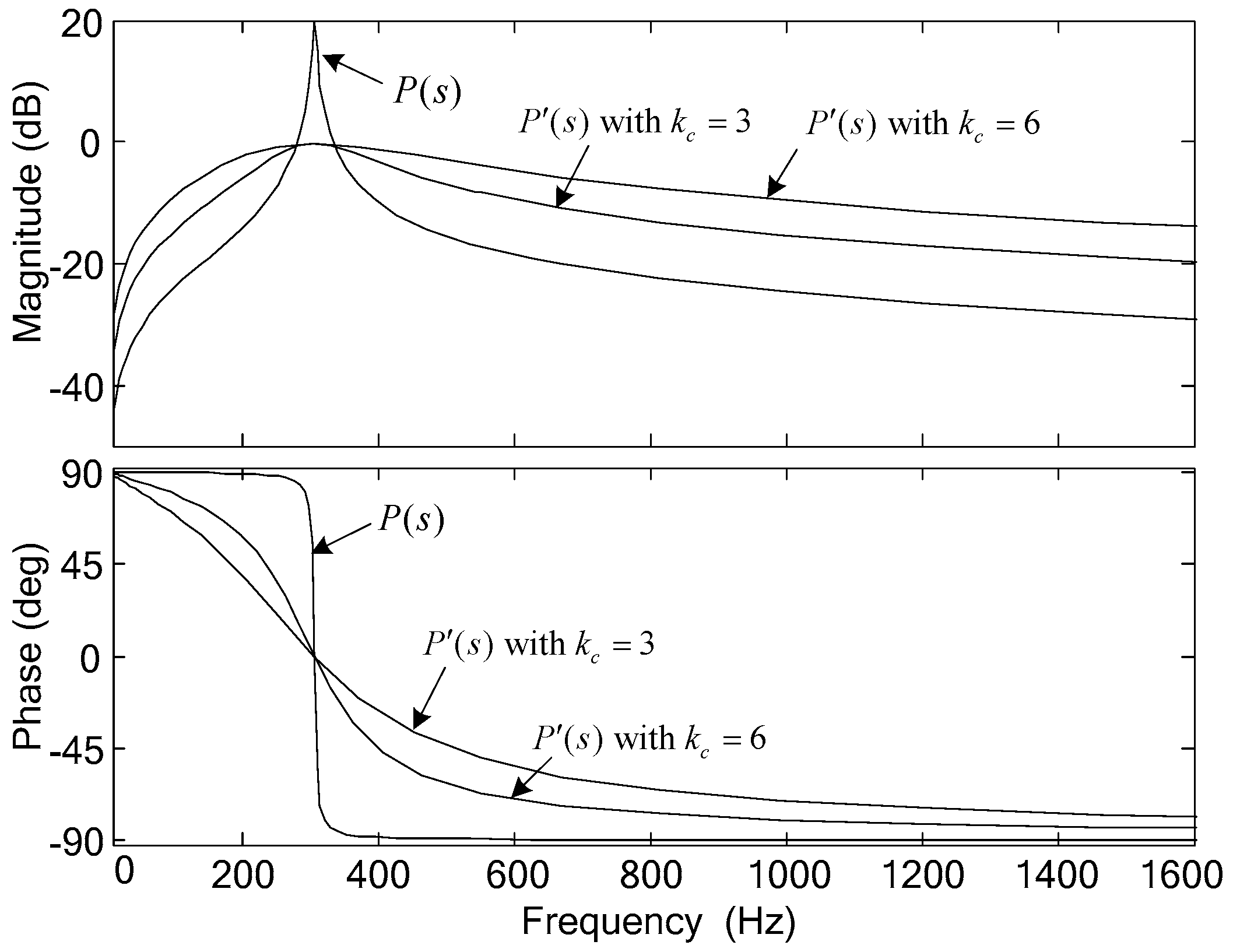
Figure 6, the modified plant expression is given by
Equation (25) reveals that
can be viewed as R becomes 1 (
), while L, C become
and
times their original values in P(s), respectively. The bode plots of
P(
s) and
are shown in
Figure 7, with
,
,
. As seen,
has cancelled the resonant peak appearing in
P(
s), and presents the characteristics of a band-pass filter. The passband width depends on the value of
. A larger
leads to a bigger passband width and smaller phase lead/lag.
In
Figure 7, without the repetitive controller, the tracking error
between the reference
and output
is
where
should be designed to guarantee the stability of
.
With the proposed 6
k + 1 repetitive controller, the tracking error
can be written as
where
is the compensation function, and
By the small gain theorem, a sufficient condition for ensuring (27) stable can be given as
Clearly,
is true. To make (29) true, it only needs
to be satisfied. Thus,
can be chosen as
where
and
are the functions of
and
in Laplace domain, respectively;
is a low-pass filter.
Moreover, on the premise of system stability, it can be derived that the numerator of (27) has such a steady-state relationship:
Equation (31) indicates that the 6k + 1 repetitive control scheme can eliminate the steady-state error of 6k + 1 harmonics tracking in D + d Ts (i.e., T0/6), which means the proposed repetitive control scheme could have a much faster transient state response than the traditional one.
5. Experimental Results
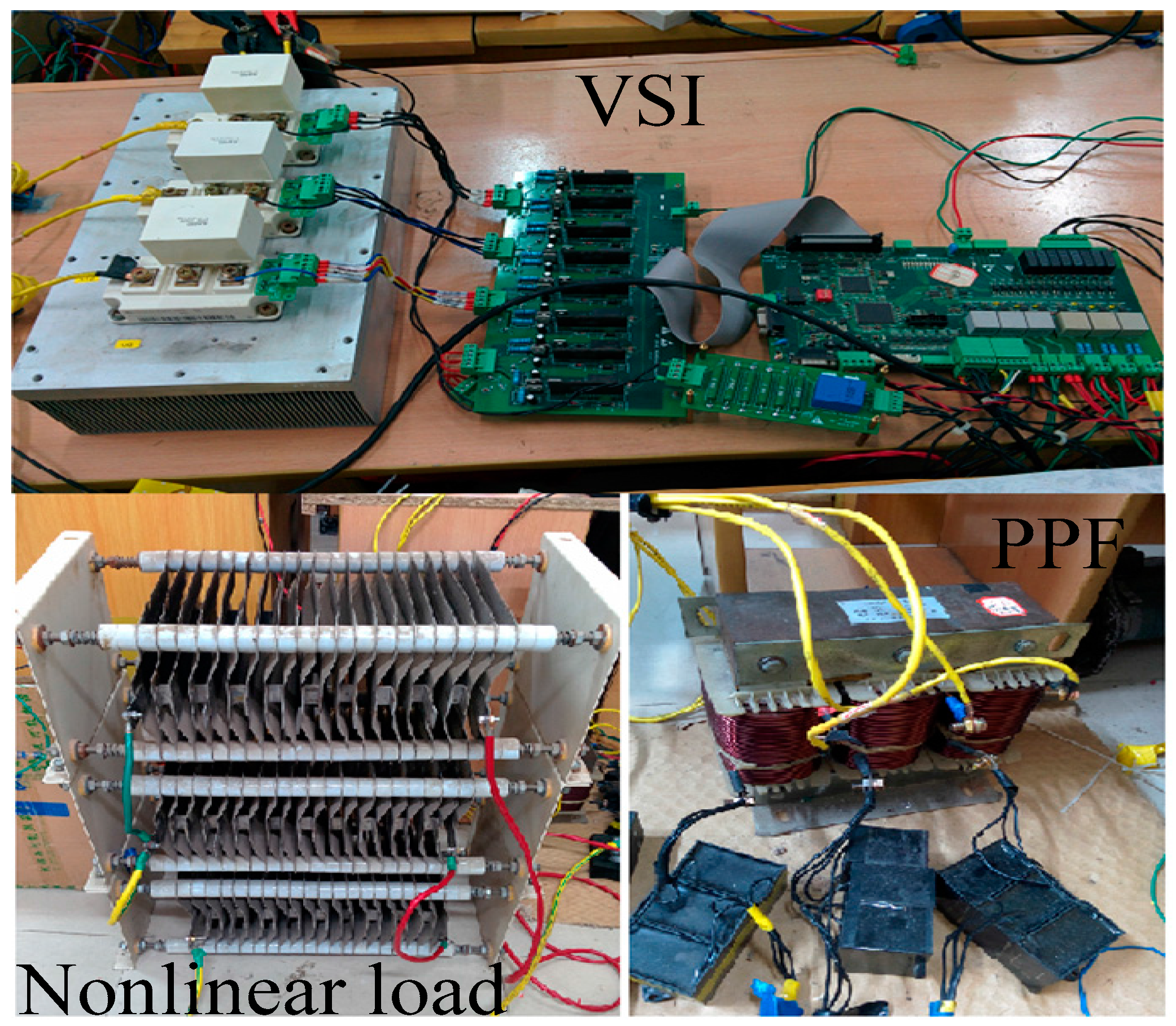
To validate the correctness and effectiveness of the proposed 6
k + 1 repetitive control scheme, a prototype of a three-phase parallel hybrid APF was built in the laboratory, which is shown in
Figure 8. The control system is realized by a combination of digital signal processor TMS320F28335 and field programmable gate array FPGA EP2C8T144C8N. The power switches use three Infineon IGBT modules and the drive circuit uses M57962L driver chips. The non-linear load used in the experiments is a three-phase diode rectifier bridge with resistive load. The overall experimental parameters are given in
Table 1.
5.1. Controller Parameters
In the implementation of experiments, the parameters of the controllers are given as follows.
- (1)
Dc-link voltage PI controller: , .
- (2)
In the harmonic current tacking loop:
The zero-phase low-pass filter is given as ;
The number of delay sample is 42, and the FD filter is given as
Output current state feedback gain ;
PI controller in the plug-in repetitive controller: , .
The compensation function
is given as
5.2. LC Filter Parameters
As the non-linear load used in this paper is a three-phase diode rectifier bridge with resistive load, the 5th, 7th, 11th, 13th harmonic currents are dominant in the load current. Assuming that the load harmonic currents are fully compensated by the hybrid APF, the voltage drop across the LC filter by the injected compensating harmonic current is
where
is the m-th order harmonic component of load current, and
is the amplitude of
.
For the hybrid APF, the design objective of the LC filter is to offer a lowest possible impedance path for injecting harmonic currents, in other words, to minimize the voltage drop . Thus, the dc-link voltage rating of VSI can be minimized.
Then, an optimization function can be given as
where
is the individual m-th order harmonic distortion rate, and
is the amplitude of fundamental component in the load current.
The capacitor C in the LC filter can be chosen by the rule as follows:
where
is the reactive power demanded by load,
is the grid frequency,
is the grid voltage amplitude.
Assume the capacitor C has been determined, such as C = 90 uf. According to Figure 11b, it can be seen that , , and . Substituting the above parameters into (32), the optimal inductor L can be determined as L = 2.8 mH. So we can choose L = 3 mH for the hybrid APF experimental prototype without loss of much performance, and the resonant frequency of the LC filter is 306 Hz.
5.3. Experimental Results
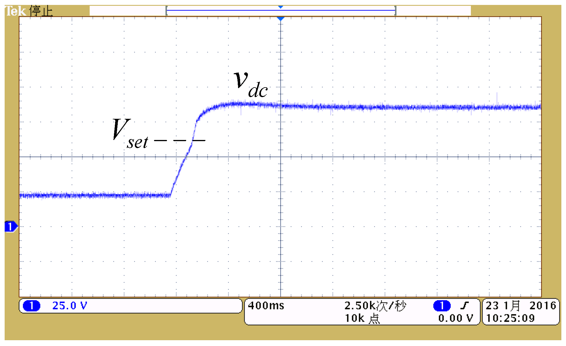
Figure 9 shows the dynamic behavior of the dc-link capacitor voltage in the start-up process. To avoid the inrush current caused by the capacitors, the series-resistance soft-start mode was used in the experiments. Specifically, when
, the IGBTs are turned off, the capacitors are charged up with small current due to the series-resistance; when
, the series-resistance is bypassed and then the PWM pulses will be activated.
reaches the setting value 80 V in the steady state, which verifies the correctness of the dc voltage control strategy.
To validate the static and dynamic performances of the proposed 6
k + 1 repetitive control scheme, the related experimental results are shown in
Figure 10,
Figure 11,
Figure 12 and
Figure 13. For the sake of simplicity, only the a-phase waveforms are displayed.
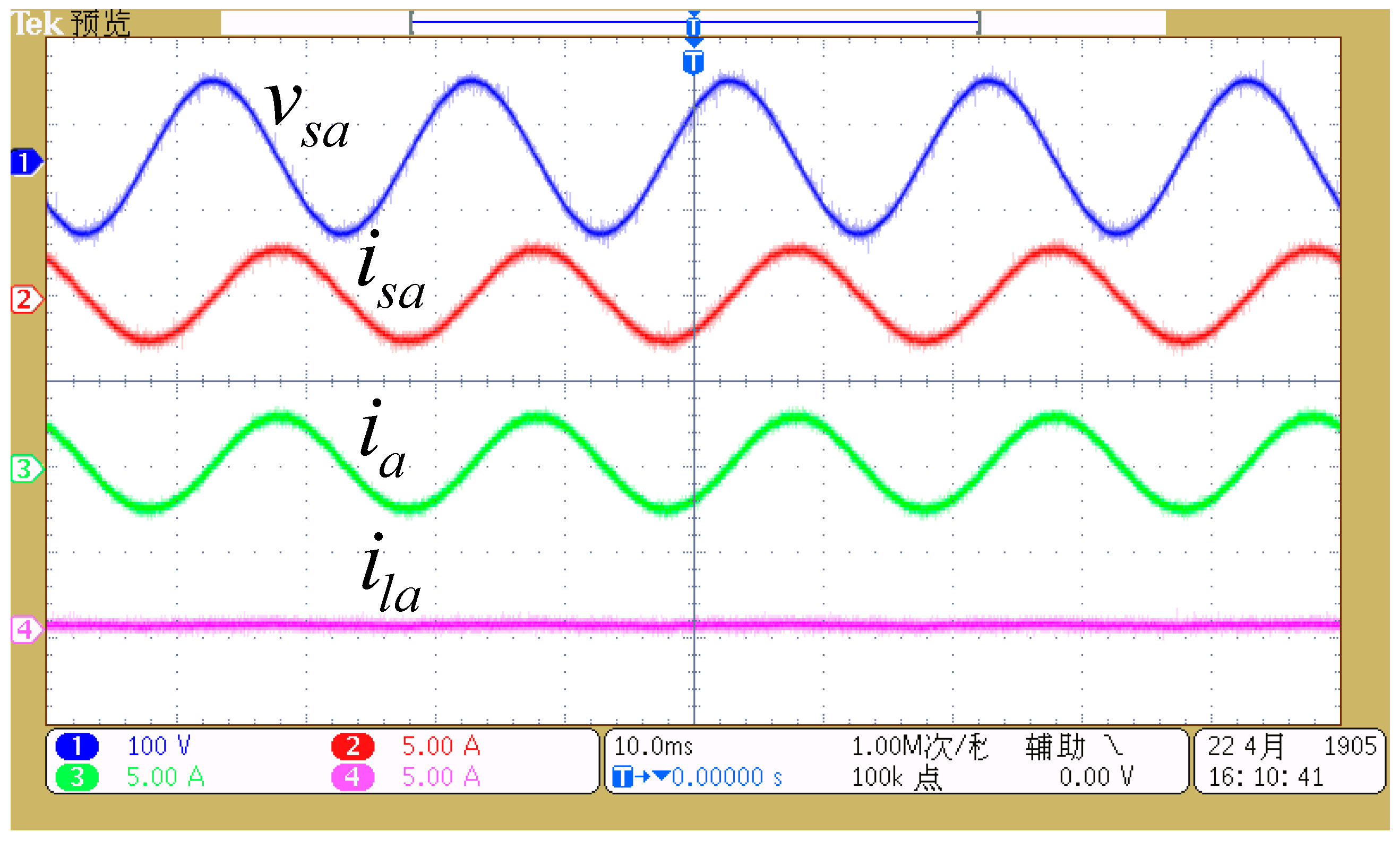
Figure 10 shows the harmonic compensation results when a nonlinear load is disconnected (
). As seen,
, and
is almost the reactive power current provided by the LC filter. The waveform of
is sinusoidal with less distortion, which indicates that the proposed repetitive control scheme can well suppress the undesired harmonic components.
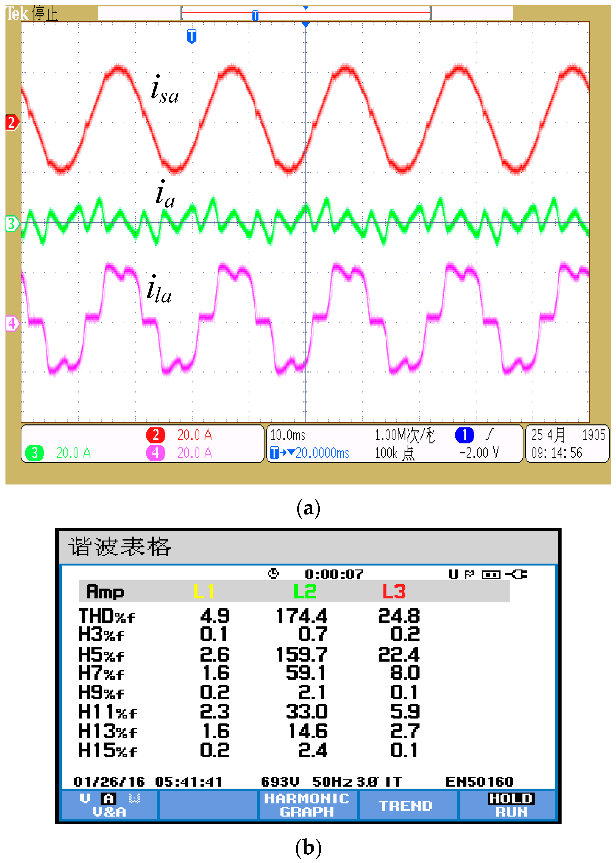
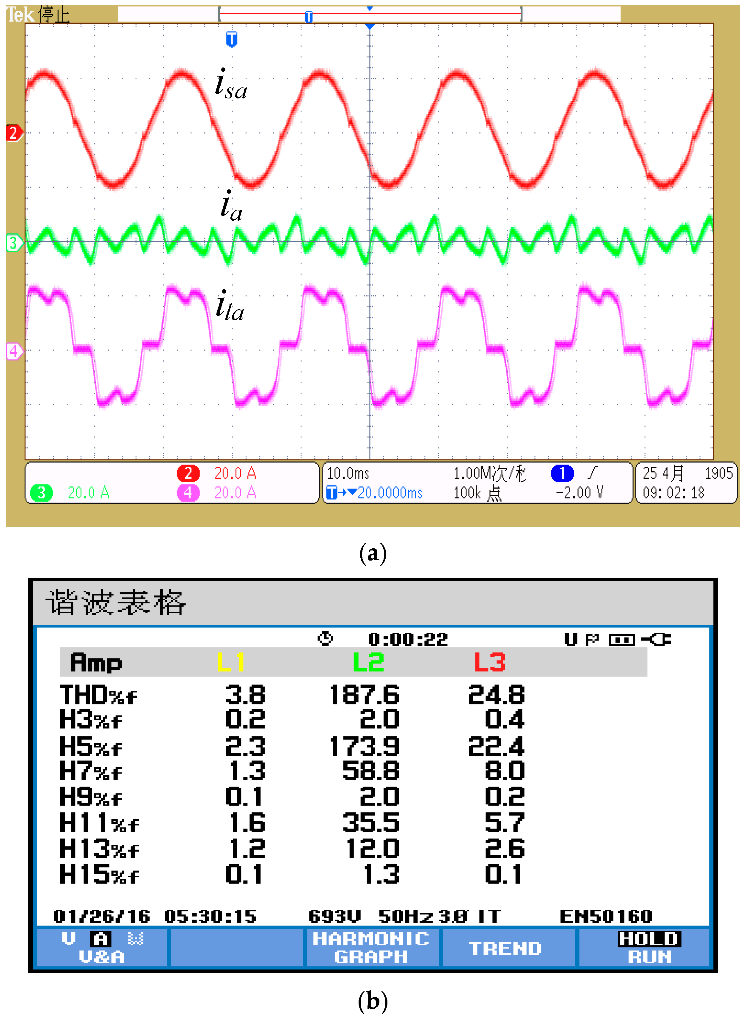
Figure 11 and
Figure 12 show the steady-state harmonic compensation results with and without fractional delay compensation when the nonlinear load is connected, respectively. In
Figure 11, the total harmonic distortion (THD) of the source current
is reduced to 3.8% from 24.8% (THD of the load current), and the distortion ratio of 5th, 7th, 11th, and 13th harmonics in
are reduced to 2.3%, 1.3%, 1.6%, and 1.2%, respectively. As a comparison, the THD of
is 4.9% in
Figure 12. These comparison experimental results demonstrate the good static performance of the 6
k + 1 repetitive controller and the effectiveness of the fractional delay compensation.
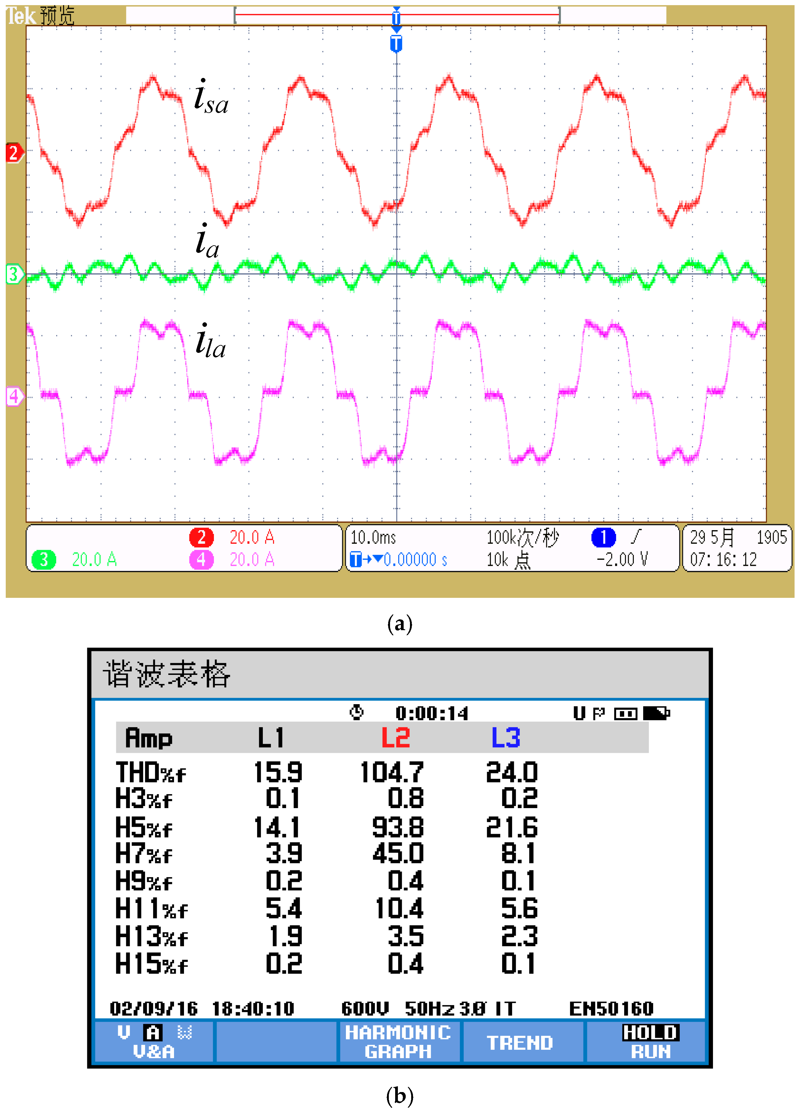
Also, to highlight the effectiveness of the 6
k + 1 repetitive control scheme, the harmonic compensation results by only the LC filter are shown in
Figure 13. As seen, the source current is still highly distorted after the compensation of the LC filter, with a THD of 15.9%. The main reasons are that the resonant frequency of the LC filter is not precisely tuned at a domain harmonic frequency, and the performance of the LC filter seriously depends on the internal resistance of the grid source.
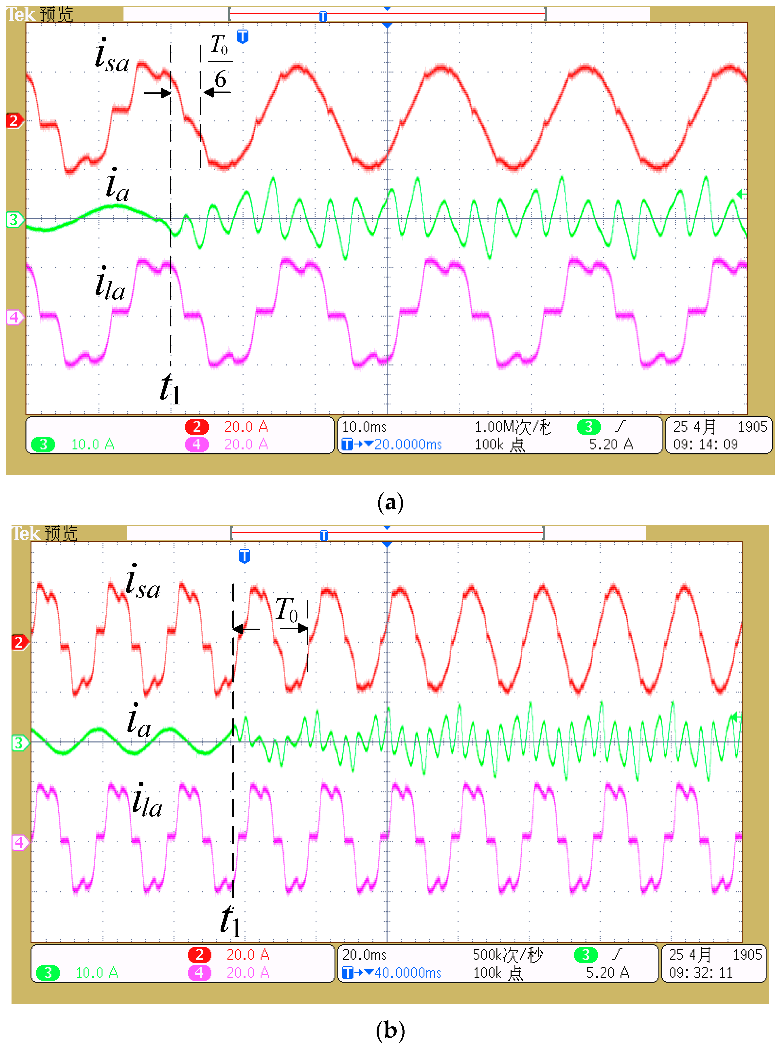
To verify the dynamic performance of the 6
k + 1 repetitive control scheme,
Figure 14 shows the comparison experimental results of the proposed and traditional repetitive control schemes in the transient process. As seen, before time
, the harmonic compensation function is not enabled,
is only the reactive power current provided by the LC filter with sinusoidal waveform, and
is distorted by the load harmonics. At time
, the harmonic compensation function is enabled. The 6
k + 1 repetitive control scheme can take effect after
T0/6 time, and eliminate the steady-state error of harmonic tracking quickly. As a comparison, the traditional repetitive control scheme takes effect after T
0 time, and needs several
T0 periods to eliminate the steady-state error. The experimental results demonstrates that the 6
k + 1 repetitive control scheme has a much better dynamic performance than the traditional repetitive control scheme, which is consistent with the theoretical analysis.


