
A Comparative Study of Novel Topologies of Magnetic Gears

Department of Electrical Engineering, The Hong Kong Polytechnic University, Hung Hom, Kowloon, Hong Kong, China
*
Author to whom correspondence should be addressed.
Energies 2016, 9(10), 773; https://doi.org/10.3390/en9100773
Submission received: 21 July 2016
/
Revised: 17 September 2016
/
Accepted: 20 September 2016
/
Published: 26 September 2016
Abstract
:The magnetic gear (MG) is an emerging technology that has been proved to possess superior performance over the conventional mechanical gear in many aspects. However, the existing markets of traditional mechanical gears have not yet been replaced by MGs. One of the major reasons is that MGs are susceptible to the permanent magnet (PM) materials, which are scarce and expensive, while mechanical counterparts are impervious to that. To solve such issues, the comparative studies of various designs of triple-layer PM-excited MGs are carried out to find out the optimal torque per unit PM volume design. The methodology of the Tabu algorithm is coupled with the finite element method (FEM) to search out the optimal solution of MGs.
1. Introduction
Limited by the frictional loss and low efficiency, conventional mechanical gears have gradually been substituted by emerging magnetic gears (MGs) in the last decade [1,2]. Compared with conventional mechanical gears, the merits of MGs also include overload protection, less maintenance requirements, noise reduction, contactless operation, and less usage of lubrication [1]. On account of the improved performance of MGs in high torque density, high efficiency, and improved reliability, it has a board range of applications. In recent years, MGs have been widely used in the field of aerospace, marine-propulsion, and renewable energy [3]. Inspired by MGs, many permanent magnet (PM) machines integrated with MGs have been proposed and proven to produce a higher torque density than the conventional PM machines [4,5,6]. However, MGs still have not completely substituted mechanical gears in industrial markets because of the increased usage of PMs, which have limited supplies and suffer from unpredictable price fluctuations. For the sake of reducing the employment of PMs and still keep the torque-density of MGs at a high level, different structures of MGs and various arrangements of PMs have been investigated to maximize the torque-density of MGs [7,8,9]. Hereto, the surface-mounted arrangement of PM arrays in MGs is widely considered the foundation of all the concentric circular-structure MGs. Particularly, a configuration of triple-layer PM-excited MGs has gained plentiful graces from researchers for its great progress in torque density increment [8]. Although the advanced arrangements of PM in previous studies contribute tremendously to the existing knowledge of MGs, there is room for further improvement in the PM arrangements in gears [8]. The motivation of this paper is to fill in this gap to further increase the torque per unit PM volume of MGs.
Five novel triple-layer PM-excited MGs with various PM arrays in the inner rotor are proposed in this article. The torque per unit PM volume rates of new designs were improved by optimizing the geometric dimensions via the finite element method (FEM) coupled with the Tabu search algorithm. In the designs of MGs, transmitted torque should be maximized, and PM material utilization should be minimized, which are tradeoffs and required optimization. In this paper, the control variate method is used, such that the PM utilization is fixed in several different volumes, and the structures of different types of MGs are optimized and compared. To show the advantages of the proposed MGs, comparative studies among proposed designs and the conventional design are also carried out.
2. Working Principle and Structure
Generally, the triple-layer PM MG is one type of MG in which the outer rotor, the stationary modulator, and the inner rotor have PMs. In this paper, the consequent-pole PMs are placed both in the outer rotor and the modulators, but the inner layer PM arrays are optimized. The configuration of the MG is shown in Figure 1 [5]. If the magnetic field excited by a p pole-pair of PMs is modulated with modulation poles, the resultant modulated harmonics produced by either of the PM rotors is calculated based on the following equation:
and the rotational velocity is given by
The gear ratio is given by
where m = 1, 3, 5, …, , k = 0, 1, 2, …, ; p is the PM pole-pair number; ns is the modulation pole number; is the rotational velocity of the PM rotor.
For the proposed triple-layer PM MGs, the bidirectional modulation effect is being exploited. The flux modulation effect is more complicated than that in conventional MGs. In the inner airgap, the magnetic field excited by the outer and middle PMs of the proposed MG is modulated through the middle and outer ferrite poles and interacts with the inner PMs. Additionally, the magnetic field excited by the inner PMs will be modulated through the middle ferrite poles and interacts with the magnetic field produced by outer PMs. The interactions are similar in the outer airgap.
In the proposed gear, there are 21 pole-pairs of outer rotor PMs, 4 pole-pairs of inner rotor PMs, and 25 pole-pairs of stator PMs. All PMs are radially magnetized to form a pair of magnetic poles with their adjacent ferrite segment. Consequently, the PM pole-pair numbers on the three layers are, respectively, p1 = 21, p2 = 25, and p3 = 4 from outer to inner. Firstly, one considers the magnetic field excited by the inner rotor PMs. The fundamental component in airgap is p3 = 4. Moreover, the modulation pole-pair number is 25 on the stator. Consequently, a series of harmonic components can be excited, and the rotational velocity of harmonics is expressed as
where i = 1, 3, 5, …, ; j = 0, 1, 2, …, ; is the inner rotor speed. When i = 1 and j = −1, the 21st harmonic component will react with the fundamental field produced by outer rotor PMs; when i = 1 and j = 0, the 4th harmonic component will react with the fundamental field produced by inner rotor PMs to produce a constant torque. Similarly, the rotational velocity of the harmonics excited by the stator PMs and modulated with inner pole teeth are given as
When i = 1 and j = −1, the 21st harmonic component will react with the outer magnetic field; when i = 1 and j = 0, the 25th harmonic component will react with the stator PMs to produce a constant torque. The harmonics and the rotational velocity of the harmonics excited by the PMs on the stator modulated with the outer pole teeth are given as
where is the rotational velocity of the outer rotor. When i = 1 and j = −1, the 4th harmonic component will react with the inner magnetic field; when i = 1 and j = 0, the 25th harmonic component will react with the stator PMs to produce a constant torque. The rotational velocity of harmonics excited by the PMs on the outer rotor and modulated by ferrite poles on stator are given as
When i = 1 and j = −1, the 4th harmonic component will react with the inner rotor PM; when i = 1 and j = 0, the 21st harmonic component will react with the outer rotor PMs to produce a constant torque.
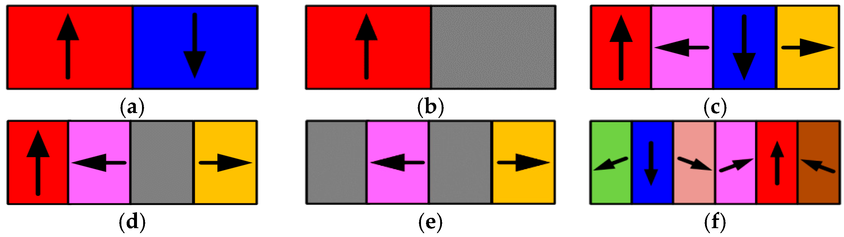
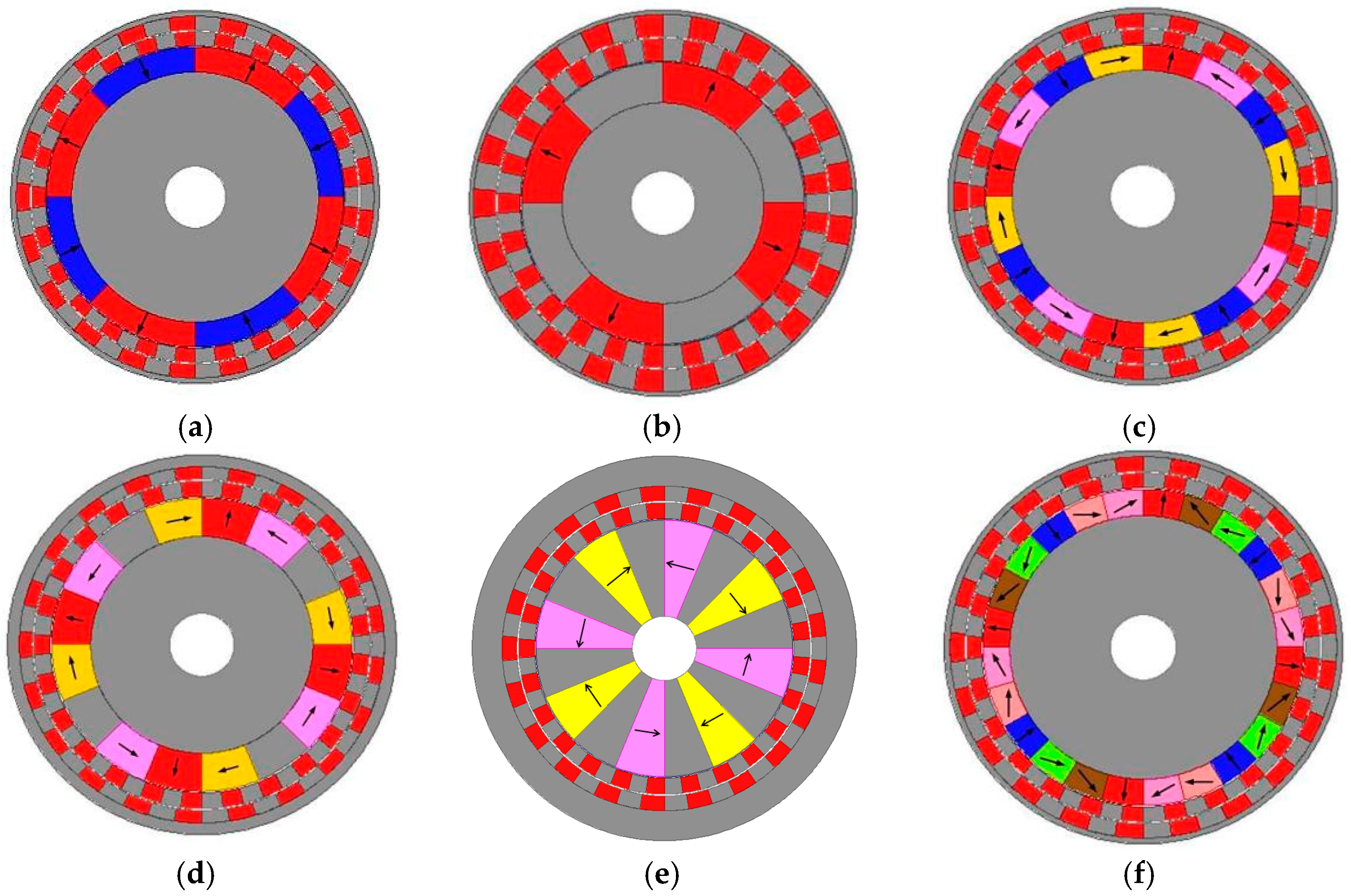
In order to improve the torque per unit PM volume of MGs, six PM arrays are used in the inner rotor as shown in Figure 2. The magnetization direction of each PM segment is labeled by the direction of arrows. The magnetization directions of PMs in the outer rotor and modulating piece in this study are all pointing outward in the radial directions. Figure 2a shows the surface mounted PM array. Figure 2b shows the consequent-pole PM array. Figure 2c shows the simplified Halbach PM array. Figure 2d shows the consequent-pole Halbach PM array. Figure 2e shows the spoke-type PM array. Figure 2f shows the improved Halbach PM array. Although only the rearrange of the inner rotor PM array is considered in this paper, the design method extended to the outer rotor PM and modulation rings are similar. Corresponding full maps of the novel arrays in a complete MG are shown in Figure 3, and the flux line distribution is given in Figure 4.
3. Optimization Approach
For the initial topology in Table 1, an optimal design method based on the Tabu algorithm coupled with the FEM is proposed to optimize the design parameters and improve the torque performance of the MGs. The Tabu search algorithm is a heuristic global optimization approach for combinatorial problems [10,11]. The traditional Tabu algorithms are rather complex and their convergence speed usually depends mostly on the selection of parameters. In this paper, the Tabu search algorithm is applied with the improvements in the following respects:
3.1. Improve the Move Criteria
In the traditional Tabu search algorithm, the current state x changes into the next state x* as long as the objective function value is improving. In this way, the local optimal solution is easier to be found than the global optimal solution by the proposed algorithm. To handle this issue, in this paper, the local best solution is used as the current one instead of the global best solution to begin its subsequent iterations.
3.2. Set a Normalized Step Vector
A normalized step vector was used here. Variables in different directions are all normalized into [0, 1] first, then a series of feasible moves are produced around the current best solution according to a standard step vector h, which is given by
The step vector can be carried out for each direction, and the new state in the jth direction is given as
where L denotes the personal defined step size, (1000 is proposed in this paper to determine a minimal step-size 0.001 in h ); r is randomly generated in the interval [−1, 1]; pj is the coefficient vector p in the jth direction, which is given by , (j = 1, 2, …, n), and bj and aj denote the range of pj. n represents the preferred number of candidates in each one generation. Note that hi = 1 is always satisfied to guarantee the global searching ability.
The application of the described operators goes on until there is no improvement during sufficient iterations (20 is proposed) or a given number of iterations accomplished.
3.3. Set a Constraint of Permanent Magnetic (PM) Volume
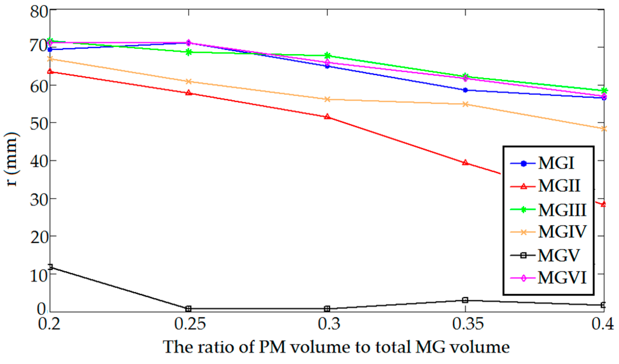
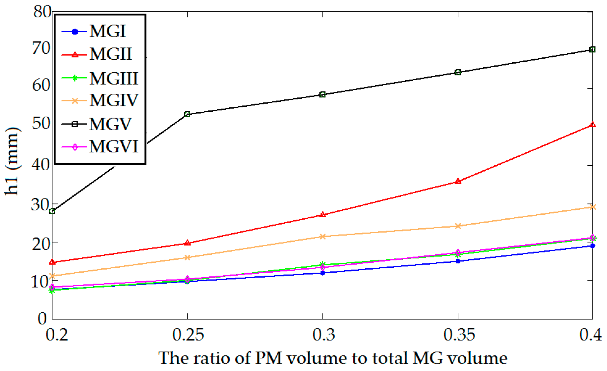
During the optimization, the outside radius (Ro), shaft radius (ri) and air gap width (a) is fixed. For the configuration of MG under study, a total of four parameters, including the height of the inner rotor’s PM layer (h1), the height of stator’s segments (h2), the height of outer rotor’s PM layer (h3), and the inner radius of inner PM layer (r), directly govern the distribution of PM magnetic flux, and the torque density of the MG as well. The optimal design problem of the magnetic gear can be formulated as a bi-objective optimization of torque (f1) and the PM volume (f2) as given below:
where x donates the optimization parameters (r, h1, h2, h3). From the function above, the optimization of MGs is a multi-objective problem. As mentioned in the Introduction section, the multi-objective problem can be simplified to a single-objective problem by fixing the PM volume. Because the structure of a MG is a standard cylinder, the operations about volume can be simplified to operations about area in a cross section.
In this situation, the PM area distributions in three layers, namely the inner rotor, the outer rotor, and the modulation rings, are optimized, but the total PM usage is constrained. In other words, under the condition of the constrained volume and cost of the MG, the torque of the MG should be optimized. Therefore, the sum of the three layers of the PM areas should match the constraint, which can be described as a function below:
where represent the PM area of the inner layer, the middle layer, and the outer layer, respectively. represents the total area of a MG. is a coefficient defined to indicate the percentage of the PM area in the MG. From the configuration of the MGs, it can be easily deduced that, for MG I, MG III, MG VI,
for MG II and MG V,
for MG IV,
For each type of MG in this study,
By substituting Equations (13)–(16) into Equation (12), a variable can be omitted on account of being expressed by other variables. To simplify operations, variable r is chosen to be omitted. Therefore, the fitness function can be simplified as
in which F donates the output torque of the MG.
4. Comparative Study of Magnetic Gears (MGs)
For each Tabu algorithm iteration, the objective function is to maximize the output torque by the computation using the FEM. Then, based on the optimal solution obtained, the optimized solution of each MG topology is also acquired. When the PM volume is set as 40% of the volume of the entire materials, the final results of the maximum torque of each MGs and corresponding parameters are listed in Table 2. The static curves of the torque of each MGs are shown in Figure 5.
Considering that the PM usage in MGs may change according to practical requirements, the MGs with the ratio of the PM volume to total MG volume ranging from 0.2 to 0.4 are optimized in this paper. The maximal torque variations of each MG with a different PM ratio are shown in Figure 6.
The parameter changes of each MG including r, h1, h2, and h3 are also shown in Figure 7, Figure 8, Figure 9 and Figure 10, respectively. From these results, one can see that, with the same PM usage, the MGs with different PM arrays have various torque performance. When PM usage is the lowest, namely 0.2, MG II produces the highest maximal torque among these MGs. However, when the ratio increases to 0.4, MG II produces the lowest maximal torque density among these six structures. Overall, it is shown that the torque of MG I and MG II have a tendency towards saturation as the PM material usage increases in MG. It is also shown that, with the increasing usage of PM material, there is a rapid increase in the maximal torques of MG V and MG IV, but for MG II the torque increases relatively slowly due to the flux saturation caused by its PM structure and MG volume limitation. The Halbach PM array-based MG presents a higher torque density, especially in cases where the proportion of the PM volume is larger than 0.35.
The size of the MGs may change according to practical requirements. Optimized PM arrays with one specific size may not produce the largest torque when the size of the gear changes. To solve this problem, another numerical experiment is done to measure the maximal torques with the changed volume of the MGs. The simulation is done with a PM-volume-to-total-gear-volume ratio of 0.35. The length of the gear is fixed, and the area of the gear is scaled twofold and fourfold, and is shrunk to half and fourth of its original size. As shown in Figure 11, the results indicate that, for each gear, the torque increases with the MG volume at a fixed proportion of growth. Consequently, when the size of the gear is scaled up and out, but its topology stays unchanged, its torque increases and reduces. They have a linear relationship.
The torque density of each MG design is shown in Table 3. It clearly indicates that the torque density of each MG design increases as the proportion of PM material scales up. Additionally, as shown in Table 4, it is noteworthy that the variation tendency of torque per PM is not always increasing. The most PM-saving design is MG II in a 0.2 PM ratio. Only in 0.25 and 0.3 PM ratios does the conventional design, namely MG I, have the best performance. In a low PM cost situation (a 0.2 PM ratio), MG II can produce about 5% more torque density than the conventional MG design. In the case of a high PM demand (a 0.4 PM ratio), MG VI can produce about 10% more torque density than the conventional one.
5. Conclusions
This paper presents five PM arrays in the inner rotor for triple-PM-excited MGs. Comparisons of the torque between MGs with the proposed arrays and the conventional array are carried out. After geometry optimization, it is found that Halbach PM MGs and the MG with inset PM arrays can produce a higher maximal torque than conventional MGs with surface-mounted PMs, in the case where the MG outer diameter is constrained, but PM material usage is not constrained. However, if aiming to reduce the cost of MGs, namely with a small ratio of PM volume to total MG volume, the conventional MG and consequent PM-pole MG have a greater chance of producing an improved torque.
Acknowledgments
This work was supported by the Research Grant Council of the Hong Kong Government under project PolyU 152130/14E.
Author Contributions
Shuangxia Niu conceived the main idea and Yuan Mao performed the experiments and analysis. All of the work was done under the supervision of Shuangxia Niu.
Conflicts of Interest
The authors declare no conflict of interest.
Abbreviations
The following abbreviations are used in this manuscript:
| MG | magnetic gear |
| PM | permanent magnet |
| FEM | finite element method |
References
- Atallah, K.; Howe, D. A novel high-performance magnetic gear. IEEE Trans. Magn. 2001, 37, 2844–2846. [Google Scholar] [CrossRef]
- Atallah, K.; Calverley, S.D.; Howe, D. High-performance magnetic gears. J. Magn. Magn. Mater. 2004, 272, 1727–1729. [Google Scholar] [CrossRef]
- Li, W.; Chau, K.T.; Jiang, J.Z. Application of linear magnetic gears for pseudo-direct-drive oceanic wave energy harvesting. IEEE Trans. Magn. 2001, 47, 2624–2627. [Google Scholar] [CrossRef] [Green Version]
- Niu, S.; Ho, S.L.; Fu, W.N. Performance analysis of a novel magnetic-geared tubular linear permanent magnet machine. IEEE Trans. Magn. 2011, 47, 3598–3601. [Google Scholar] [CrossRef]
- Ho, S.L.; Niu, S.; Fu, W.N. Transient analysis of a magnetic gear integrated brushless permanent magnet machine using circuit-field-motion coupled time-stepping finite element method. IEEE Trans. Magn. 2010, 46, 2074–2077. [Google Scholar] [CrossRef]
- Atallah, K.; Rens, J.; Mezani, S.; Howe, D. A novel “Pseudo” direct-drive brushless permanent magnet machine. IEEE Trans. Magn. 2008, 44, 4349–4352. [Google Scholar] [CrossRef]
- Jian, L.; Chau, K.T. A coaxial magnetic gear with halbach permanent-magnet arrays. IEEE Trans. Energy Convers. 2010, 25, 319–328. [Google Scholar] [CrossRef] [Green Version]
- Peng, S.; Fu, W.N.; Ho, S.L. A novel high torque-density triple-permanent-magnet-excited magnetic gear. IEEE Trans. Magn. 2014, 50, 1–4. [Google Scholar] [CrossRef]
- Niu, S.; Chen, N.; Ho, S.L.; Fu, W.N. Design optimization of magnetic gears using mesh adjustable finite-element algorithm for improved torque. IEEE Trans. Magn. 2012, 48, 4156–4159. [Google Scholar] [CrossRef]
- Glover, F. Tabu search-Part 1. ORSA J. Comput. 1989, 1, 190–206. [Google Scholar] [CrossRef]
- Glover, F. Tabu search-Part 2. ORSA J. Comput. 1990, 2, 4–32. [Google Scholar] [CrossRef]
Figure 1.
Triple-layer permanent magnet (PM) magnetic gear construction.
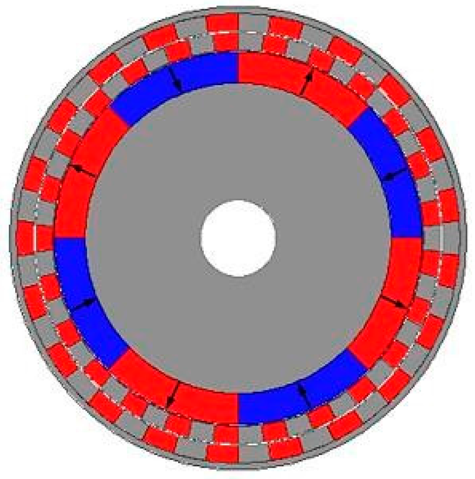
Figure 2.
PM arrays: (a) Surface-mounted PM array; (b) Consequent-pole PM array; (c) Halbach PM array I; (d) Consequent-pole Halbach PM array; (e) Inset PM array; (f) Halbach PM array II.
Figure 2.
PM arrays: (a) Surface-mounted PM array; (b) Consequent-pole PM array; (c) Halbach PM array I; (d) Consequent-pole Halbach PM array; (e) Inset PM array; (f) Halbach PM array II.

Figure 3.
Magnetic gears (MGs): (a) Surface-mounted PM array; (b) Consequent-pole PM array; (c) Halbach PM array I; (d) Consequent-pole Halbach PM array I; (e) Spoke-type PM array; (f) Halbach PM array II.
Figure 3.
Magnetic gears (MGs): (a) Surface-mounted PM array; (b) Consequent-pole PM array; (c) Halbach PM array I; (d) Consequent-pole Halbach PM array I; (e) Spoke-type PM array; (f) Halbach PM array II.

Figure 4.
Flux line distributions of MGs: (a) MG I; (b) MG II; (c) MG III; (d) MG IV; (e) MG V; (f) MG VI.
Figure 4.
Flux line distributions of MGs: (a) MG I; (b) MG II; (c) MG III; (d) MG IV; (e) MG V; (f) MG VI.
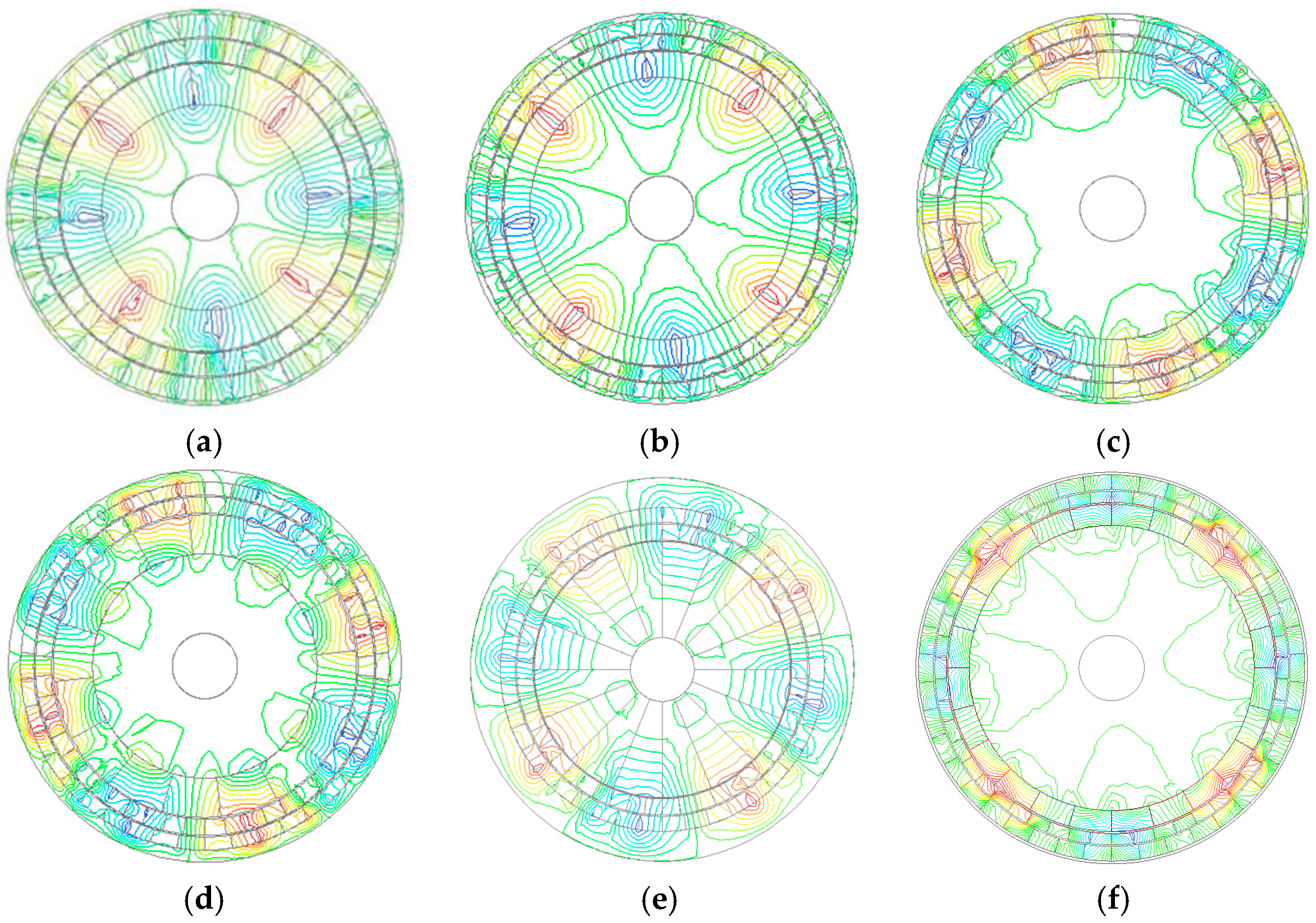
Figure 5.
The static curves of torque of MGs.
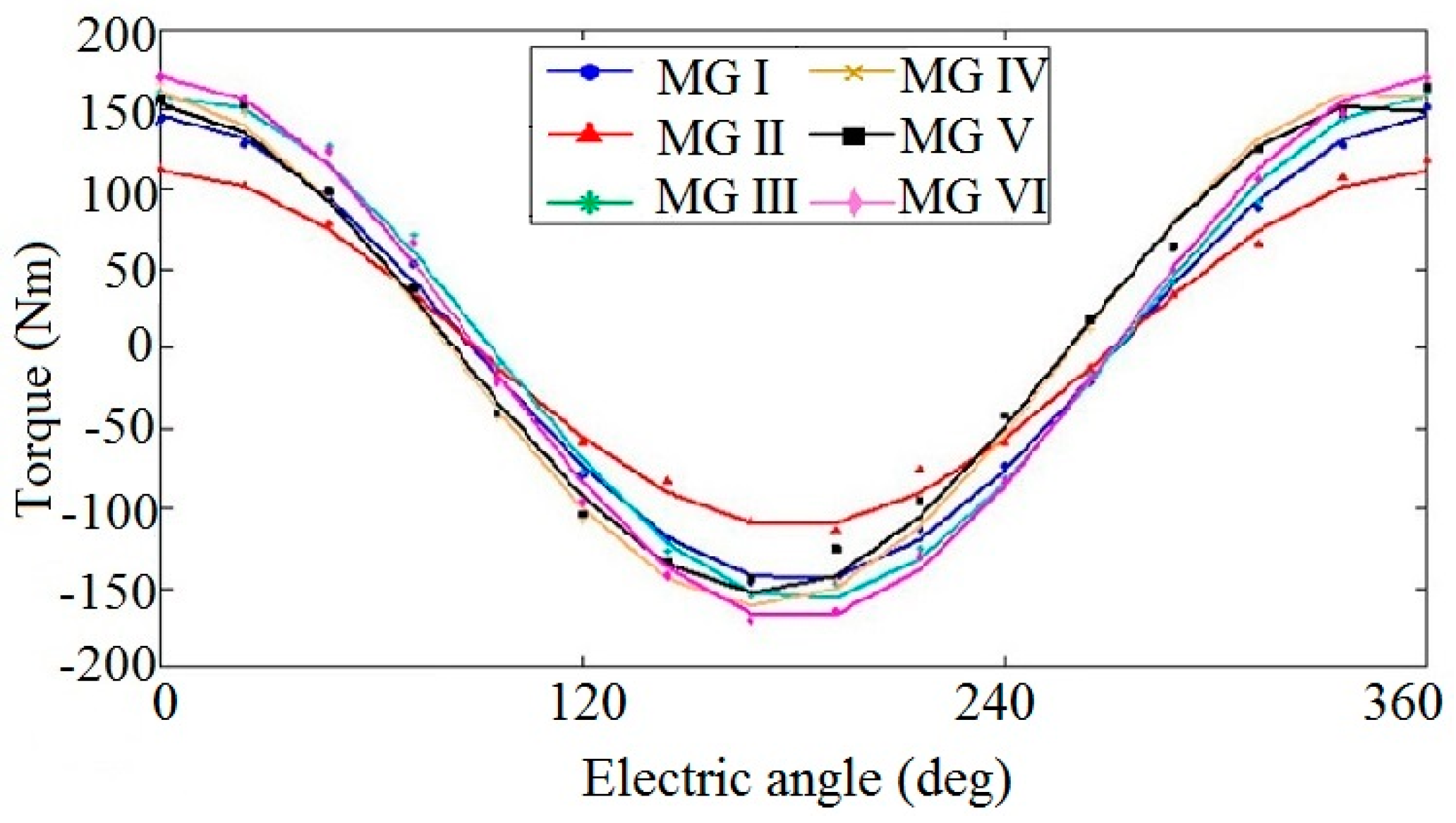
Figure 6.
Maximal torque of MGs in different PM usage.
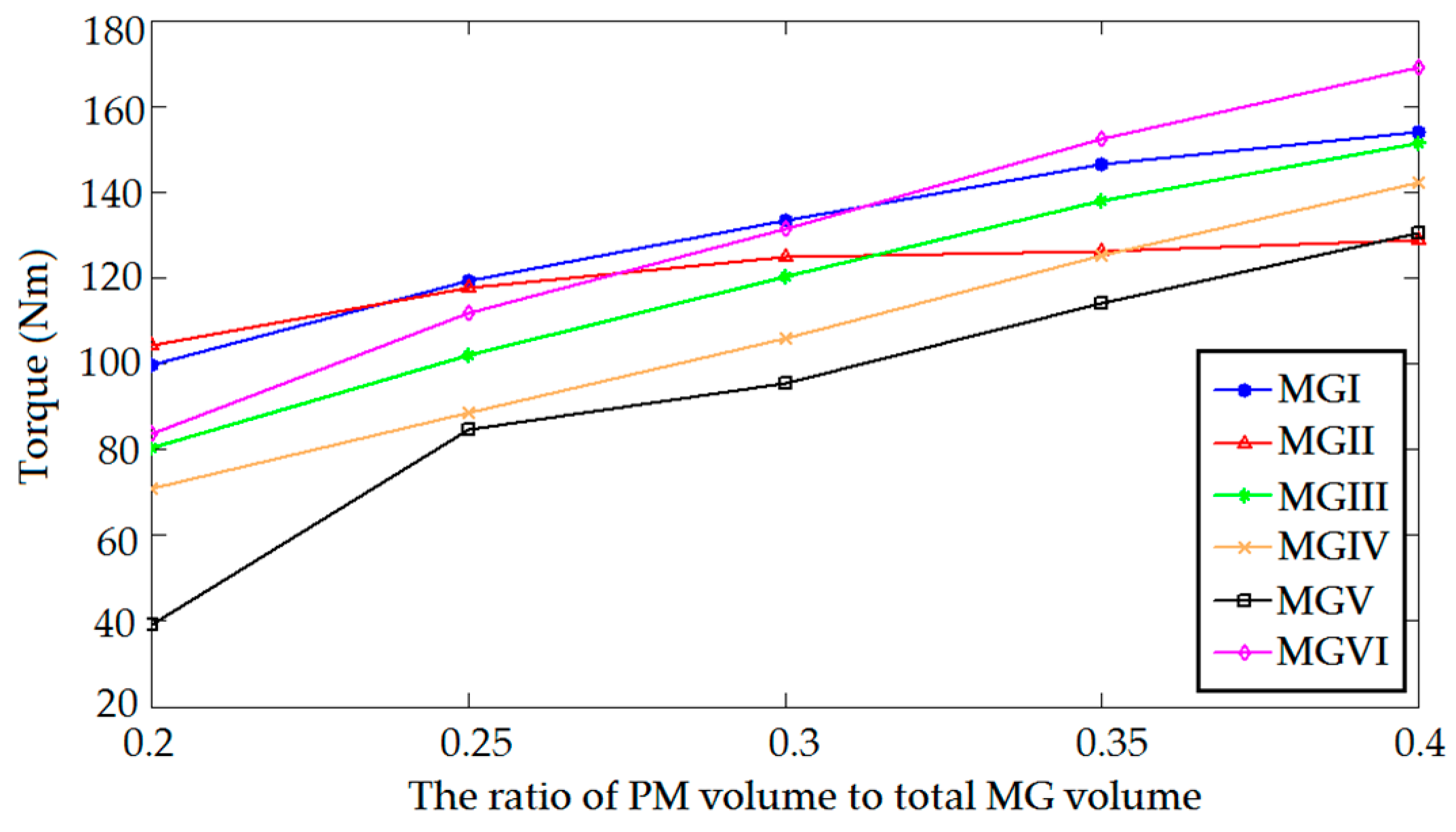
Figure 7.
The optimized inner radius of the inner PM layer (r) versus the different PM usages of the MGs.
Figure 7.
The optimized inner radius of the inner PM layer (r) versus the different PM usages of the MGs.

Figure 8.
The optimized height of the inner PM layer (h1) versus the different PM usages of the MGs.
Figure 8.
The optimized height of the inner PM layer (h1) versus the different PM usages of the MGs.

Figure 9.
The optimized height of the stationary modulation poles (h2) versus the different PM usages of the MGs.
Figure 9.
The optimized height of the stationary modulation poles (h2) versus the different PM usages of the MGs.
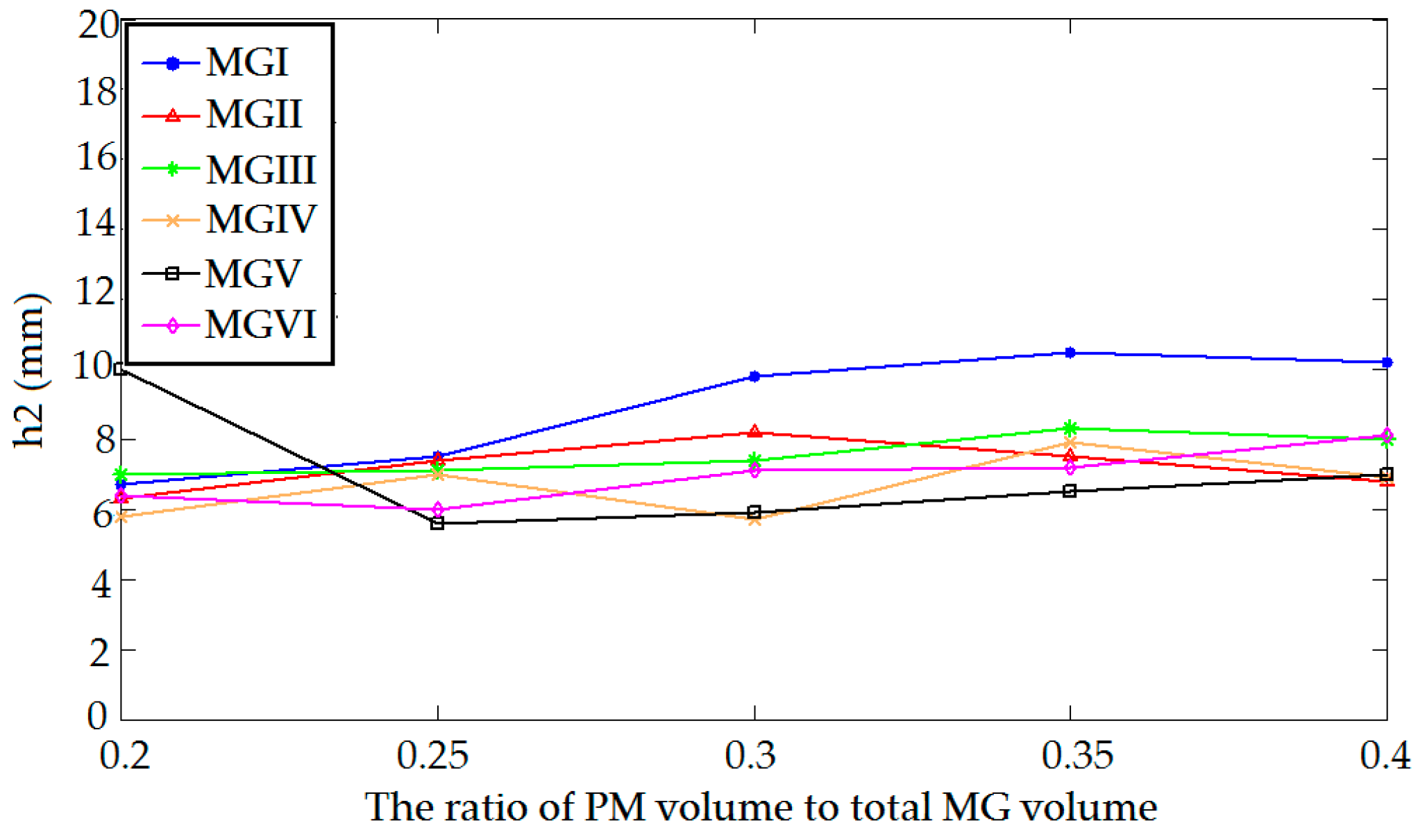
Figure 10.
The optimized height of the outer PM layer (h3) versus the different PM usages of the MGs.
Figure 10.
The optimized height of the outer PM layer (h3) versus the different PM usages of the MGs.
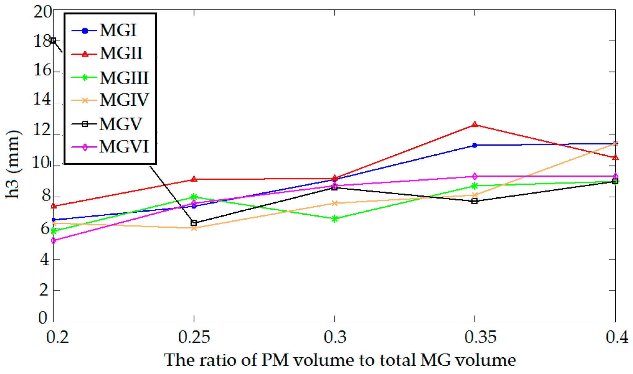
Figure 11.
Torque of MGs in different scales (a ratio of 0.35).


| Items | MG (I, III, VI) | MG (V) | MG (II) | MG (IV) |
|---|---|---|---|---|
| Pole pair No. in inner rotor | 4 | 4 | 4 | 4 |
| PM segment No. in modulation rings | 25 | 25 | 25 | 25 |
| Pole pair No. in outer rotor | 21 | 21 | 21 | 21 |
| Air-gap length (mm) | 1 | 1 | 1 | 1 |
| Outside radius (mm) | 120 | 120 | 120 | 120 |
| Shaft radius (mm) | 20 | 20 | 20 | 20 |
| Inner radius of inner PM layer (r) (mm) | 65 | 20 | 62.5 | 68.6 |
| Height of inner PM layer (h1) (mm) | 20 | 25 | 25 | 24 |
| Height of stationary ring (h2) (mm) | 15 | 14 | 14 | 10 |
| Height of outer PM layer (h3) (mm) | 15 | 14 | 14 | 8 |
| Shaft depth (mm) | 100 | 100 | 100 | 100 |
| Remanence of NdFeB (T) | 1.1 | 1.1 | 1.1 | 1.1 |
| Parameters | MG (I) | MG (II) | MG (III) | MG (IV) | MG (V) | MG (VI) |
|---|---|---|---|---|---|---|
| r | 58.7 | 39.3 | 62.3 | 55.0 | 3.0 | 61.7 |
| h1 (mm) | 15.0 | 35.7 | 16.8 | 24.2 | 64.2 | 17.2 |
| h2 (mm) | 10.5 | 7.5 | 8.3 | 7.9 | 6.5 | 7.2 |
| h3 (mm) | 11.3 | 12.6 | 8.7 | 8.1 | 7.7 | 9.3 |
| Torque (Nm) | 146.5 | 126.3 | 138.0 | 125.3 | 114.0 | 152.3 |
| PM Ratio | MG (I) | MG (II) | MG (III) | MG (IV) | MG (V) | MG (VI) |
|---|---|---|---|---|---|---|
| 0.2 | 70.7 | 74.0 | 57.0 | 50.6 | 28.0 | 59.8 |
| 0.25 | 85.2 | 84.0 | 72.7 | 63.3 | 60.3 | 79.8 |
| 0.3 | 95.1 | 89.1 | 85.9 | 75.7 | 68.1 | 93.9 |
| 0.35 | 104.5 | 90.2 | 98.5 | 89.5 | 81.4 | 108.8 |
| 0.4 | 109.9 | 91.9 | 108.1 | 101.5 | 93.0 | 120.7 |
| PM Ratio | MG (I) | MG (II) | MG (III) | MG (IV) | MG (V) | MG (VI) |
|---|---|---|---|---|---|---|
| 0.2 | 353.5 | 370.0 | 285.0 | 253.0 | 140.0 | 299.0 |
| 0.25 | 340.8 | 336.0 | 290.8 | 253.2 | 241.2 | 319.2 |
| 0.3 | 317.0 | 297.0 | 286.3 | 252.3 | 227.0 | 313.0 |
| 0.35 | 298.6 | 257.7 | 281.4 | 255.7 | 232.6 | 310.9 |
| 0.4 | 274.8 | 229.8 | 270.3 | 253.8 | 232.5 | 301.8 |
© 2016 by the authors; licensee MDPI, Basel, Switzerland. This article is an open access article distributed under the terms and conditions of the Creative Commons Attribution (CC-BY) license (http://creativecommons.org/licenses/by/4.0/).
Share and Cite
MDPI and ACS Style
Niu, S.; Mao, Y. A Comparative Study of Novel Topologies of Magnetic Gears. Energies 2016, 9, 773. https://doi.org/10.3390/en9100773
AMA Style
Niu S, Mao Y. A Comparative Study of Novel Topologies of Magnetic Gears. Energies. 2016; 9(10):773. https://doi.org/10.3390/en9100773
Chicago/Turabian StyleNiu, Shuangxia, and Yuan Mao. 2016. "A Comparative Study of Novel Topologies of Magnetic Gears" Energies 9, no. 10: 773. https://doi.org/10.3390/en9100773
Note that from the first issue of 2016, this journal uses article numbers instead of page numbers. See further details here.