
A Novel Method to Balance and Reconfigure Series-Connected Battery Strings


1
State Key Laboratory for Manufacturing Systems Engineering, Xi’an Jiaotong University, Xi’an 710049, Shaanxi, China
2
School of Mechanical Engineering, Xi’an Jiaotong University, Xi’an 710049, Shaanxi, China
*
Author to whom correspondence should be addressed.
Energies 2016, 9(10), 766; https://doi.org/10.3390/en9100766
Submission received: 2 June 2016
/
Revised: 18 September 2016
/
Accepted: 19 September 2016
/
Published: 22 September 2016
Abstract
:Cell failure and imbalance are critical problems in battery storage systems, especially in series-connected battery strings. The reconfiguration function and the balancing function are both of great importance, but it is very challenging and problematic to own both functions simultaneously. This paper attempts to make contributions on realizing both functions through new circuits and new control strategies. Firstly, a reconfigurable balancing circuit is proposed, which is able to simultaneously balance and reconfigure the battery string. In the circuits, a new way to achieve passive balancing with no bleeding resistor is realized, and the failure cells in the battery string can be bypassed with the same circuits. By taking advantage of fewer switches in the circuits, the method owns the merits of low cost and low system complexity. Secondly, to efficiently balance and reconfigure the battery string, a control strategy is proposed according to the unique structure of the circuits. Thirdly, the reconfigurable balancing circuits are fabricated and an experimental test workbench is established. The reconfigurable balancing circuits and the control strategy are validated in the experimental test workbench. The experimental results indicate that the proposed method is able to realize both the balancing function and the reconfiguration function well, and the performance of the battery string can be maintained and improved significantly. The improvements are 13% and 34% for 4 cell- and 100 cell- series-connected battery strings, respectively.

1. Introduction
Due to pollution and the energy crisis, research in new energy, such as electric vehicles (EVs), photovoltaic power (PV), wind power, etc., has increased worldwide [1,2]. Battery energy storage systems (BESSs) are frequently used in such applications [3,4,5]. To cope with the power and energy demands for such applications, a large number of battery cells, hundreds or even thousands, must be connected in series or in parallel. With so many battery cells utilized in BESSs, especially for the series-connected battery strings, the imbalanced cell problem cannot be ignored.
Manufacturers have tried to select and place the same cells in a battery string, with the same state of charge (SOC), self-discharge rate, capacity, etc. However, no two cells are identical in practice, even when they are in the same production pool and the same production batch. Slight differences in these cells lead to a large mismatch after a certain period of use. Some cells may have less capacity, and these cells will hit the discharging voltage limitation earlier when discharging. As a result, the system will have to shut down the entire battery string for safety, and the good cells in the string cannot be fully discharged. Consequently, the total capacity of the battery string will decrease. The charging process is the same, in which the good cells cannot be fully charged. Treated as an entirety for the cells in the battery string, any cell can influence the entire battery string’s performance according to the “bucket effects”.
Balancing or equalization is considered as the main solution to the problems stated above, and many balancing schemes and circuits have been presented in previous studies [6,7,8,9,10]. Balancing is sufficient when the capacities of the cells in the battery string are almost the same with only SOC differences. However, sometimes, some cells in the battery string may fade faster than others and these cells own less capacity. In this situation, balancing works only when the capacity differences are small. When the differences are bigger, some cells in the string fail. For example, the balancing technology may not be able to make up this imbalance. Swapping the cells may be the best solution in this situation. However, cells in battery strings are normally stored in battery packs, and to swap them is very difficult, time-consuming and expensive.
Reconfiguration technology has been proposed to improve the performance and prolong the life of battery strings [11,12,13,14,15,16], which is considered as another solution to the problem stated above. A reconfigurable battery string provides the flexibility to connect or remove a single battery cell from the connection matrix, and multiple cells can be connected in a series, parallel, or in a mixture of series and parallel configurations. Kim and Shin [11] proposed a dynamic reconfiguration framework that reconfigures battery cells in a large-scale battery string and provides supply voltage online as needed. Kim et al. [12] applied the reconfiguration of storage bank technology to a hybrid electrical energy storage system to improve the cycle efficiency and capacity utilization. Song et al. [15] proposed a dynamic reconfiguration multi-cell battery topology to improve battery performance. The switch array matrix topology was developed for microbatteries and proved that the topology could transfer energy to the load without any loss of energy [17]. The reliability analysis is applied to the reconfiguration battery pack [18].
However, it should be noted that many switches and their driving circuits are needed in these technologies. As a result, reliability problems and expensive problems cannot be avoided. Additionally, due to the importance of balancing [19], independent balancing systems and reconfiguration systems must be added to the battery strings, as stated in [14], and the whole system will become very complex and expensive. To realize both the balancing and reconfiguration functions simultaneously in one simple system is difficult, and such techniques are not sufficiently discussed in literature.
The main purpose of this paper is to establish a simple, low-cost and easy-to-implement method to own both the balancing function and reconfiguration function, which is a key technique to optimize the usable capacity and keep the safety of the BESS. In this paper, a novel reconfigurable balancing circuit and control strategy for series-connected battery strings is proposed, owning both the balancing and reconfiguration functions simultaneously. Since fewer switches are utilized in the proposed method, the system is much simpler and the cost is much lower. The remainder of this paper is organized as follows: in Section 2, the structure of the proposed reconfigurable balancing circuits is explained and analyzed; the control strategy of the proposed method is analyzed in Section 3; the experiments are established in Section 4 and the experimental results are analyzed; in Section 5, the conclusions are drawn.
2. Structure Analysis of the Proposed Reconfigurable Balancing Method
In this section, several reconfiguration topologies are firstly introduced and analyzed. The novel reconfigurable balancing circuits for series-connected battery strings are then proposed and analyzed.
2.1. Existing Reconfigurable Methods
The general reconfiguration method was introduced in [12], which is referred to as T1 in this paper. In this method, parallel and series configurations can be achieved by controlling the switches ON or OFF. However, in the parallel connection, none of the cells are able to be bypassed. To solve this problem, a multi-cell battery method was proposed [15], which is referred to as T2. Compared to T1, each cell in this method can be connected to the battery string terminal by adding two switches for each cell. Thus, any cell can be selected or bypassed when in parallel connection. Similarly, the switch array matrix method, referred to as T3, has also been studied to achieve these functions [16,17]. This method is similar to T2, but fewer switches are needed. The problem for T3 compared to T2 is that T3 cannot bypass the final cell Bn. Although these methods are powerful, cost and control complexity should not be ignored when they are implemented in actual applications. A series-connected, self-reconfiguration method was proposed to reduce the cost and control complexity [13,14], which is referred to as T4. In T4, only the series configuration can be formed. By controlling the switches as ON or OFF, cells in the battery string can be bypassed.
It should be noted that the methods stated above are powerful with the reconfiguration function. Unfortunately, these methods cannot own the balancing function simultaneously. When an imbalanced problem occurs, the balancing should be carried out [20,21]. However, these methods stated above cannot carry out the balancing function efficiently. Kim [14] shared the same structure of T4, but an additional direct current to direct current (DC–DC) converter for balance should be added. However, by adding balancing as an additional independent function, the system will become expensive and much more complex, not only for control signals but also for driving circuits.
2.2. The Proposed Reconfigurable Balancing Method
Based on the analysis of these existing reconfigurable methods and the important balancing function, a new reconfigurable balancing method, which is able to reconfigure and balance series-connected battery strings simultaneously, is proposed as shown in Figure 1.
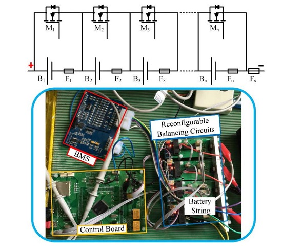
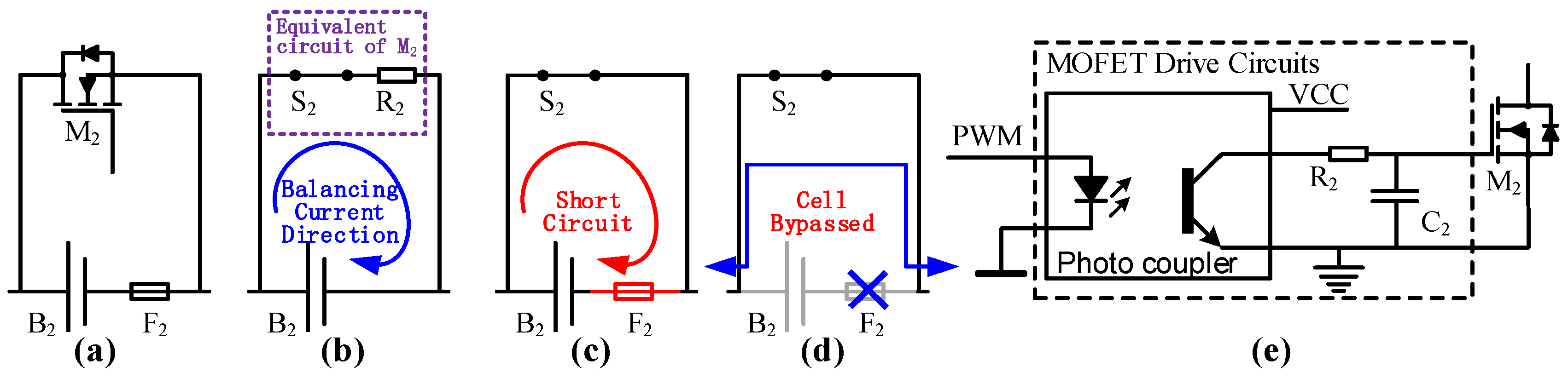
Figure 1a shows the equivalent circuits of the proposed method, where n cells are series-connected, and the cells in the battery string are denoted as B1 to Bn, and the fuses as F1 to Fn. Fs is the string fuse or so-called service fuse for the battery string, which is designed with smaller nominal current than other fuses. Since the switches in this topology are chosen as metallic oxide semiconductor field effect transistor (MOSFET), they are denoted as M1 to Mn. Each cell with a fuse and MOSFET is called a cell module, as shown in Figure 2, taking B2 for example.
The normal mode is shown in Figure 1b, when all the switches are OFF. Neither reconfiguring nor balancing is carried out in this mode. Figure 1c shows the equivalent circuit of this mode, which is similar to a standard string of series-connected batteries.
The balancing mode is shown in Figure 3a–c, when the battery string is unbalanced and several cells in the string may need to be balanced. In this mode, to realize the balancing with no bleeding resistor, the MOSFET drive circuits are designed as shown in Figure 2e. With the resistor capacitor (RC) filter (R2 and C2), the signal to MOSFET M2 becomes a DC signal. By controlling the duty ratio of the pulse width modulation (PWM), the DC signal applied to M2 is controlled and M2 is able to work on the amplifier region, and thus the balancing current can be controlled. By adopting these measures, the balancing current is controlled by changing the duty ratio of the PWM signal, and no bleeding resistor is needed. If one cell in the string, B2 for example, must be balanced, as shown in Figure 3a, the MOSFET M2 is controlled by the PWM signal. In this scenario, the cell module is equivalent as shown in Figure 2b. The MOSFET M2 is equivalent to a series-connected switch and resistor, and the fuse is equivalent to a conductor. Note that the resistor R2 shown in Figure 2b is the equivalent resistance of the MOSFET, rather than the fuse. Therefore, when S2 is ON, the energy stored in B2 will be released by resistor R2, which is actually released by the MOSFET M2. By these sequences, balancing is realized, and B2 is balanced.
If more than one cell in the string has higher energy, several balancing progresses can be carried out in parallel. For instance, when B2 and B3 need to be balanced, M2 and M3 are controlled by the PWM signal. Similarly, when B2 and Bn must be balanced, M2 and Mn are controlled by the PWM signal. Any other scenarios can be performed in the same manner.
The reconfiguration mode should be utilized, as shown in Figure 3d–f, when cells fail due to aging (capacity fading), open circuit, short circuit, etc. If one cell has failed, taking B2 for example, as shown in Figure 3d, MOSFET M2 is controlled by an ON signal. In this scenario, the cell module is the equivalent of a short circuit as shown in Figure 2c. Since fuse F2 is in the loop, the short circuit current is large enough to break the fuse within a short period. Thus, after this short period, the new configuration of the battery string is as shown in Figure 2d and Figure 3d. It is clear that cell B2 is bypassed in the string, and the new battery string is healthy again.
When more than one cell fails, taking B2 and B3 for example, MOSFET M2 and M3 will both be controlled by ON signal, and fuses F2 and F3 will be broken. The new battery string will be as shown in Figure 3e. Similarly, when B2 and Bn fail, M2 and Mn will be ON, and F2 and Fn will be broken, as shown in Figure 3f. Any other scenarios can be treated in the same manner.
From the analysis above, it is obvious that the proposed topology owns not only the balancing function but also the reconfiguration function. In addition, to illustrate the merits of the proposed topology, a comparison of the component count is shown in Table 1. The proposed reconfigurable balancing method is referred to as Tp in the table.
As shown in the table, it should be noted that the proposed method required the fewest switches, which is at least 50% less comparing to the existing reconfigurable methods. As a result, the system complexity is much simpler, considering the driving circuits and control signals. Someone may argue that the Tp needs additional n fuses that others do not need. However, fuses are much cheaper than MOSFETs. In addition, fuses are passive components, which do not need drive circuits or control signals; thus, the system is much simpler and less expensive. Furthermore, it should be noted that the exiting topologies listed in the table own only the reconfiguration function; however, the proposed topology owns both the reconfiguration function and the balancing function simultaneously. To add balancing function to the exiting topologies, the component count differences will be much bigger, and the proposed topology will be much more advantageous. It should be noted that the proposed method is a trade-off between cost and reconfiguration capability, since the reconfiguration could be used once for a certain battery cell to permanently exclude the cell from the string. However, such partial reconfiguration with balancing function is much cheaper and is suitable for practical applications.
3. Control Strategy Development for the Reconfigurable Balancing Topology
To efficiently balance and reconfigure the battery string, a control strategy for the reconfigurable balancing method is proposed in this section. The voltage-based, the SOC-based, or even the capacity-based balancing and reconfiguration control strategy can all be used according to the analysis of the proposed method. Several SOC estimation methods have been investigated in previous studies [22,23,24]. To estimate the real capacity of the cells in the battery string, capacity fading was also studied widely [25,26]. However, as the focus of this paper is the novel structure of the reconfigurable balancing method, the voltage-based control strategy is utilized, which is simple and concise for illustrating the method.
Firstly, the model of the series-connected multi-cell batteries is introduced. According to the definition of the series circuit, the output currents of series-connected batteries are the same. Thus, the current of the kth cell ik in the string is equal to the main current I:
The remaining capacity (RCap) of the kth cell in the battery string can be calculated as follows:
where NCap is the nominal capacity of the battery cell. The RCap of the battery string is calculated as follows:
The connectivity of the MOSFET of the cell can be expressed as a reconfiguration matrix (RM):
where Mk indicates the MOSFET state of the switch of kth battery cell, whose value can be denoted as:
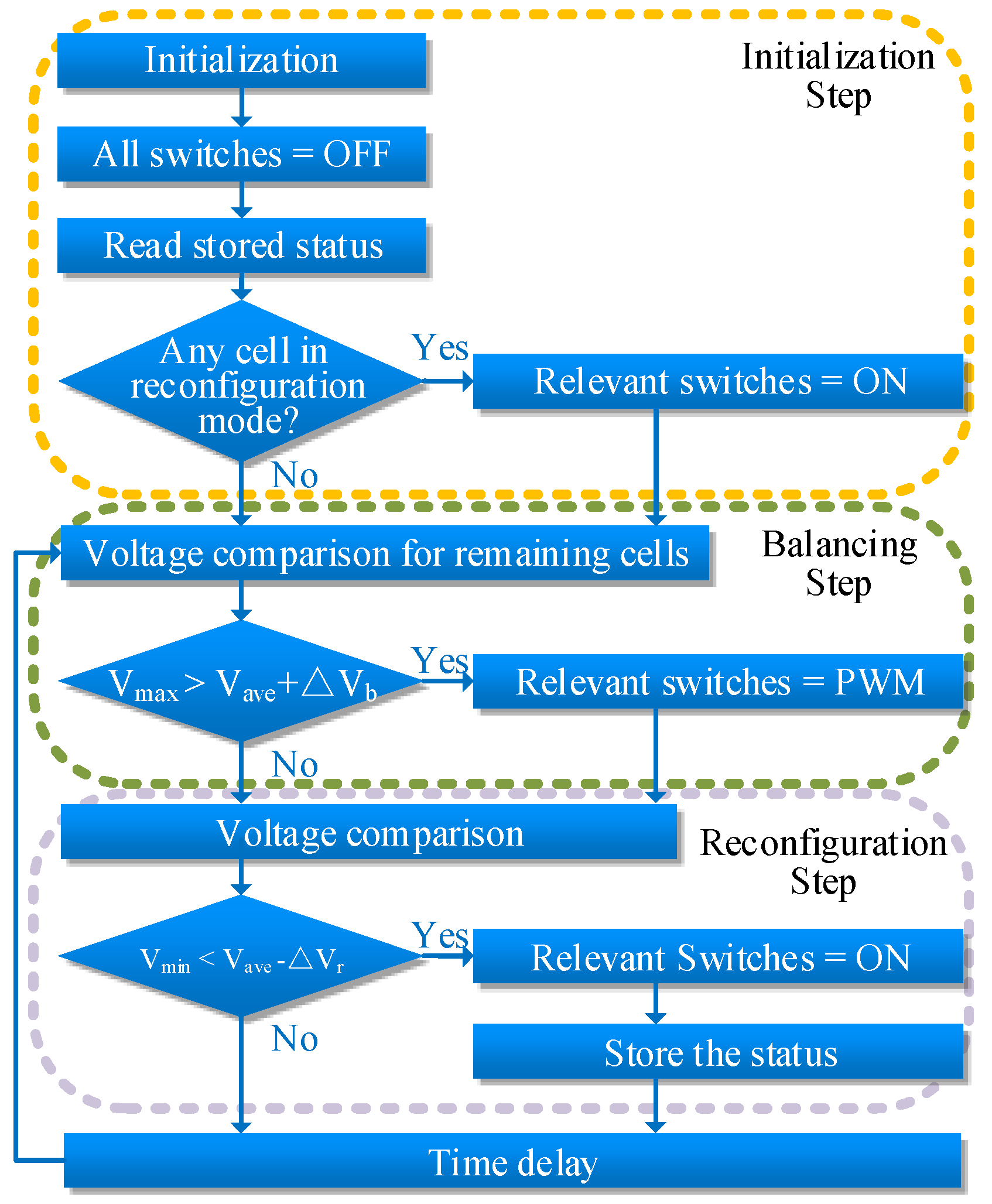
The flowchart of the control strategy is illustrated in Figure 4 to decide when to balance and when to reconfigure.
To start the procedure, the system is firstly initialized and the stored status is read. Such status can be cells in the reconfiguration mode, the SOC and the state of health (SOH) of cells, etc. Based on the stored status, the system determines which switches should be kept ON or OFF. If some cells in the battery string are in the reconfiguration mode, the relevant switches should be kept ON henceforth.
The second step is to balance the cells. The average voltage Vave, the maximum voltage Vmax and the minimum voltage Vmin are calculated. The voltages of the cells in the battery string are then compared. When Vmax is large enough to meet Equation (6), the cell Bmax that has the Vmax should be balanced.
where ΔVb means the balancing voltage bound.
When Equation (6) is true, the relevant switch for Bmax is Mmax, and Mmax should be controlled by the PWM signal. It means Bmax is in the balancing mode. According to the analysis in Section 2, the energy stored in Bmax will be dissipated through Mmax. Otherwise, if Equation (6) is false, no cell will be in the balancing mode.
Then, the reconfiguration step is carried out. There are many criteria for the decision when or how to reconfigure cells. In this section, to demonstrate the functions of the proposed topology, a voltage-based criterion is used, as shown in Equation (7):
where ΔVr denotes the reconfiguration voltage bound.
When Equation (7) is satisfied, the minimum voltage cell Bmin has less capacity and must be bypassed to improve the performance of the entire battery string. Thus, the relevant switch Mmin should be ON henceforth. Meanwhile, this Bmin will be marked in reconfiguration mode, and the status will be updated and stored for future usage.
The balancing step and the reconfiguration step will be repeated over and over again to improve the performance of the battery string.
It should be noted that the voltage-based control strategy is utilized in this study to concisely explain the unique structure and functions of the proposed method. However, if accurate SOCs or actual capacities of the battery cells could be obtained, SOC-based or capacity-based control strategy could easily be applied in the same manner.
4. Experimental Validation
4.1. Establishment of the Experimental Test Workbench
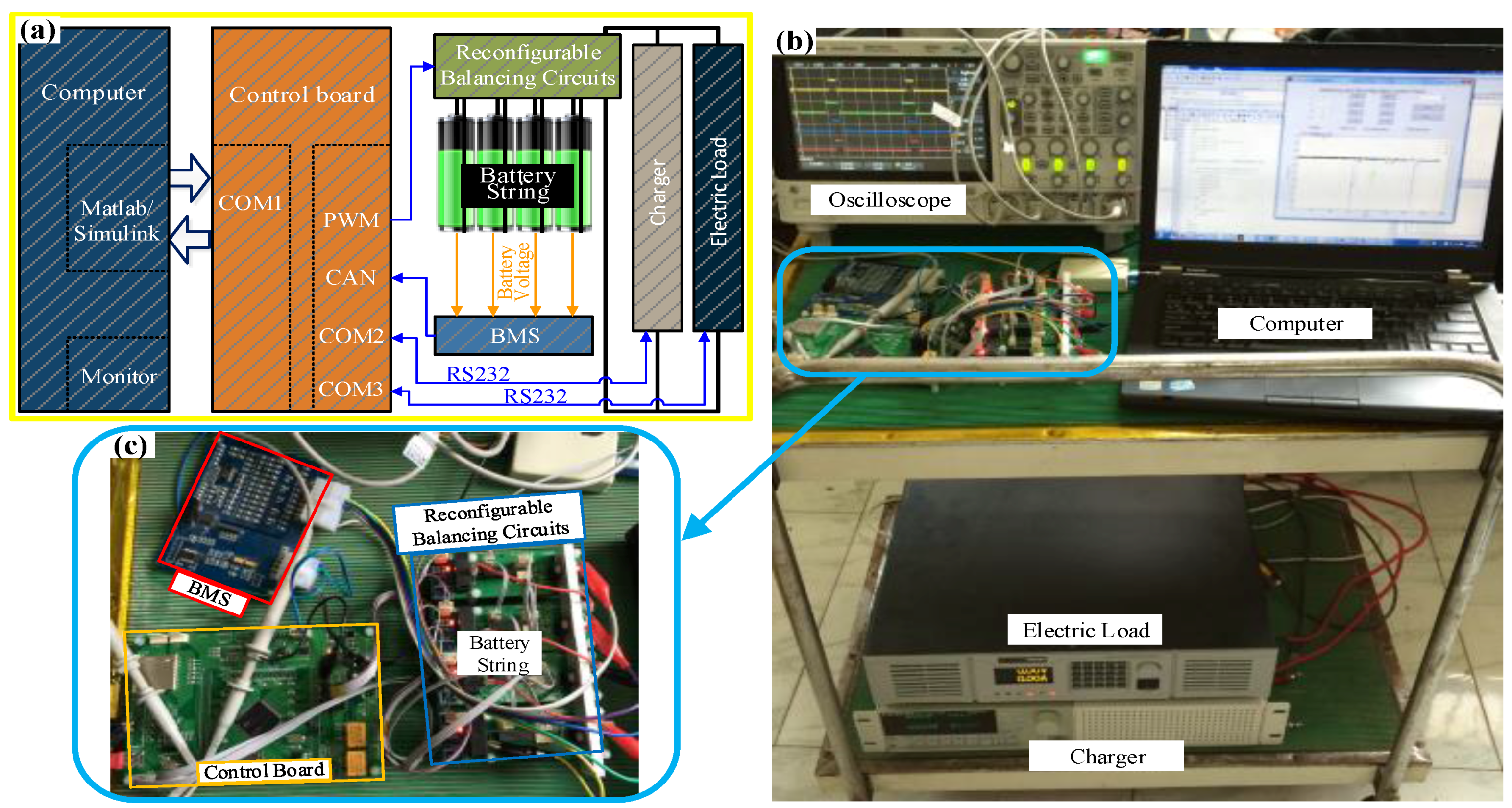
To illustrate the performance of the proposed reconfigurable balancing method and the control strategy for series-connected battery strings, the experimental test workbench is established. To clearly demonstrate the system, four cells are connected in series to form the battery string, as shown in Figure 5. The Panasonic NCR 18650 battery cell (Panasonic, Osaka, Japan) is utilized in this study. The nominal capacity of the tested battery is 2.9 Ah, with 3.6 V nominal voltage. The upper cut-off voltage and the lower cut-off voltage are 4.2 V and 2.5 V, respectively.
The configuration of the experimental test workbench is illustrated in Figure 5a. The proposed method is realized by the reconfigurable balancing circuits, which connect to the battery string. A control board controls the reconfigurable balancing circuits with ON, OFF, and PWM signals. A battery management system (BMS) monitors the status of the battery string and sends the information to the control board. The control board utilizes the information to perform the control strategy and sends signals to the reconfigurable balancing circuits to balance and reconfigure the battery string. The control board also sends battery test profiles to the electric load and the charger to emulate the current demands for the battery string in real-world applications, such as in EVs, PV storage systems, etc. Certain current profiles can be emulated and applied to the battery string, such as current demands for the urban dynamometer driving schedule (UDDS) driving cycle, the highway fuel economy test (HWFET), etc. A computer monitors and stores the experimental data.
4.2. Reconfigurable Balancing Circuits Fabrication and Fundamental Function Validation
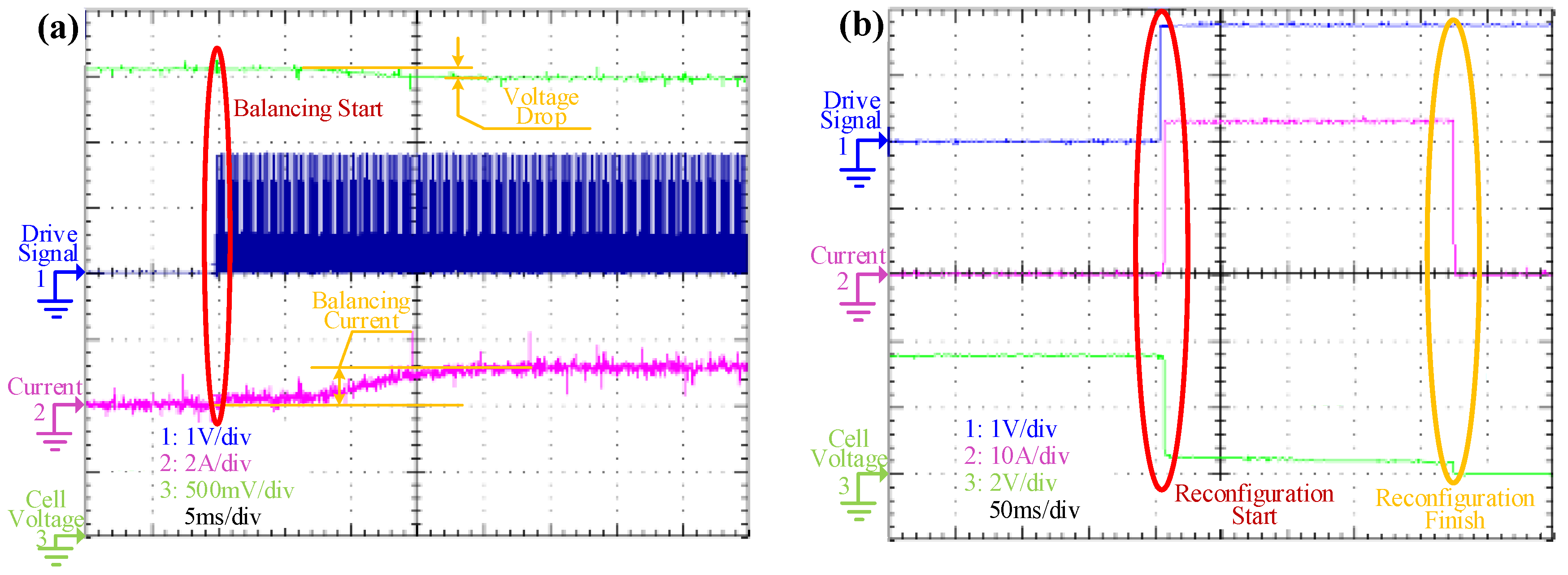
First, the reconfigurable balancing circuits shown in Figure 5c are fabricated and tested. Figure 6 shows the test results for the circuits.
Figure 6a shows the measured signals of the reconfigurable balancing circuits for the balancing mode. As shown in the figure, before the balancing mode is started, which is in the normal mode, the drive signal for the switch is OFF, and the balancing current is zero. At this moment, the cell voltage is 3.57 V. The drive signal for the switch turns out to be PWM as shown in the figure with the red ellipse, when the balancing starts. At the same time, a decrease in voltage from 3.75 V to 3.5 V is observed. Meanwhile, the balancing current turns out to be 1 A in a short time. The balancing current can be alternated by controlling the duty ratio of the PWM. From the analysis above, it is clear that the balancing process is achieved and the balancing current is 1 A.
Figure 6b illustrates the signals of the reconfigurable balancing circuits for the reconfiguration mode. As shown in Figure 6a, the signals are the same before reconfiguration starts, which is in the normal mode. When the reconfiguration mode is started, the drive signal is set to be ON. The current increases dramatically to about 24 A, lasting for about 0.2 s, and then returns to zero. The voltage of the series-connected cell and fuse drops dramatically as the current increases. The voltage continues to drop slowly, and after about 0.2 s, the voltage drops to zero. This phenomenon can be explained by the fuse breaking. When the switch is set to be ON, the battery cell, the switch and the fuse form a short circuit. With the designed nominal current of the fuse, the short circuit would last for a very short time, and the fuse would be broken. Thus, with this procedure, the fuse is damaged, and with the switch remaining ON, this cell can be bypassed. The reconfiguration mode is realized.
For the power battery, the maximum continuous discharge current is up to 5C and the maximum 10 s pulse discharge current is up to 10C. In this study, the peak current in the reconfiguration mode is about 24 A for about 0.2 s, which is about 8C and the duration of time is very short. It is safe, and little damage to the battery will result from the action.
4.3. Balancing Only Validation
To further illustrate the performance of the entire system, the battery string was applied to a current profile sequence to emulate the scenario in which the system is implemented in real applications. A UDDS drive cycle, which is frequently used in battery-related technology studies, especially in EVs, was applied to the battery string. The magnitude of the current profile was scaled down for the battery features. In the experiment, the terminal voltage and the current were measured, and the current counting method was utilized to calculate the SOCs of the cells. In this experiment, the balancing voltage bound ΔVb was set at 0.01 V, and the reconfiguration voltage bound ΔVr was set at 0.1 V.
For the first scenario, the initial SOCs for the four cells were 100%, 81%, 80%, and 79%. The experimental results for this scenario are shown in Figure 7.
Figure 7a shows the voltage results for the experiment. It is clear from the figure that the voltage differences are very large at the beginning, which can also be observed in Figure 7b. As the difference between the Vmax and the Vave is larger than ΔVb and the difference between the Vave and the Vmin is smaller than ΔVr, the balancing mode is activated. As shown in Figure 7c, the drive signal for M1 is set to be PWM when the experiment starts, since B1 has the largest voltage and is marked to be in the balancing mode. Because the minimum voltage cannot achieve the reconfiguration criterion, no cell is in the reconfiguration mode. Thus, at this moment, B1 is in the balancing mode, and the remaining three cells are all in normal mode.
The procedure shown in Figure 4 will be repeated over and over, and the reconfiguration criterion and the balancing criterion will be checked. For about 1500 s, as shown in Figure 7, B1 is always in the balancing mode. Then, the energy stored in B1 comes to almost the same as the average, and B1 switches between the balancing mode and the normal mode. This phenomenon can be explained by the voltage drop caused by the inner resistance when the balancing current flows through the battery. Finally, after about 220 s, all cells are in the normal mode because the voltage differences are small enough. To show the effectiveness of the balancing procedure, the SOCs for the four cells in the battery string are shown in Figure 7d. The SOCs of the cells converge to the average SOC quickly, which means the balancing process is efficient.
To calculate the improvements of the proposed method, the actual RCap (ARCap) of the battery string is calculated and compared. According to Equation (3), since the four cells are connected in a series, the ARCap of the battery string is determined by the minimum ARCap cell (ARCapmin), and thus, it can be calculated as follows:
In this scenario, the ARCap of the battery string without balancing or reconfiguration (ARCap1) can be calculated as:
It should be noted that, without balancing, ARCap1 will always be 3.16NCap for the battery cycles afterwards. However, after balancing, the ARCap of the battery string (ARCapafter balancing) is 4NCap, which is (4 − 3.16)/4 × 100% = 21% improvement with balancing function of the proposed topology.
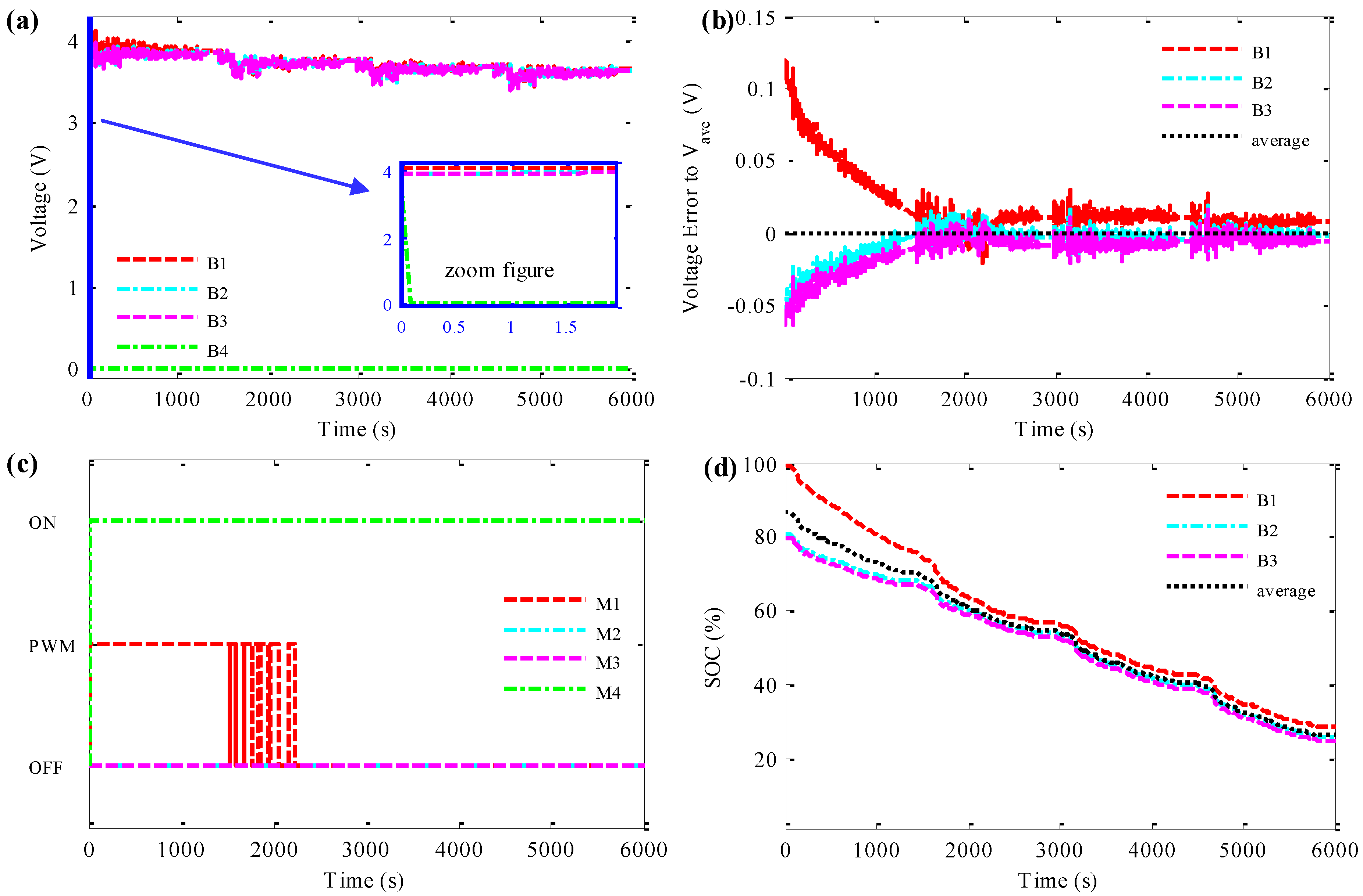
4.4. Simultaneously Balancing and Reconfiguring Validation
For the second scenario, the initial SOCs for the four cells are 100%, 81%, 80%, and 65%. The experimental results are shown in Figure 8. In this scenario, B4 is used to simulate the cell that needs to be reconfigured. As shown in Figure 8a, the voltage of B4 turns out to be zero quickly at the beginning. The phenomenon could be explained as follows:
At the beginning of the experiment, B4 has the lowest voltage. When compared to the average voltage of the four cells, the reconfiguration voltage bound ΔVr, the voltage of B4 is too small and meets the criterion for reconfiguration. Thus, B4 is marked to be in reconfiguration mode, and the drive signal for M4 is set to be ON. As stated in the previous section, when B4 is in reconfiguration mode, the voltage will drop to zero in a short time. Figure 8a, especially in the zoon figure, proves this analysis.
Since B4 is in reconfiguration mode, which is considered to be bypassed from then on, only the three remaining cells will be considered henceforth, except that M4 should be kept ON.
After the reconfiguration process, the remaining three cells form the new battery string. As shown in Figure 8a, the maximum voltage for these remaining cells is still very large, and the balancing process should also be carried out. The same as in the first scenario, B1 is in the balancing mode at the beginning, as shown in Figure 8c. Finally, the remaining three cells balanced. The SOCs of the three cells in Figure 8d also validate the reconfiguration and balancing effects.
Similarly to calculating the improvements of the proposed method in this scenario, the ARCap of the battery string without balancing or reconfiguration (ARCap2) can be calculated as:
However, after the reconfiguration and balancing processes, since only three cells are left, the ARCap of the battery string is 3NCap, which owns (3 − 2.6)/3 × 100% = 13% improvement.
The improvement may not so significant in a string of four cells connected in a series. However, in a real-world application, as stated in the first section, hundreds or thousands of cells may be connected in a series to form a battery string. Taking 100 cells connected in series, for example, if one cell in the battery string fails, with 65%NCap, then the ARCap of the entire string will be 65NCap without reconfiguration or balancing. However, if the reconfiguration and balancing processes are carried out, this cell will be bypassed, and the entire string will have about 99NCap, which owns (99 − 65)/99 × 100% = 34% improvement. From the analysis above, the proposed reconfigurable balancing method is very effective for improving the performance of the series-connected battery string, especially when cell failure exists.
5. Conclusions
A reconfigurable balancing method for series-connected battery strings, which owns both the balancing function and the reconfiguration function simultaneously, has been proposed in this paper. Compared to the existing methods, the proposed topology owns the merits of low cost and simple system complexity, which is essential for actual applications. A new way to achieve passive balancing with no bleeding resistor was realized and the failure cells in the battery string could be bypassed with the same circuits. A control strategy was proposed for the proposed circuits to efficiently reconfigure and balance the battery string. The reconfigurable balancing circuits were fabricated and an experimental test workbench was established to validate the circuits and the control strategy. The circuit testing results validated that the reconfigurable balancing circuits realized both the balancing and reconfiguration functions, with as high as 1 A balancing current and as fast 0.2 s cell bypassing. In different experimental scenarios, the proposed method was able to bypass the failed cell from the battery string to form a new healthy battery string and balance the new string for better performance. The ARCap for the battery string improved significantly, especially when cell failure exists. The ARCap of the entire string achieved 13% and 34% improvements for 4 cell- and 100 cell-battery strings, respectively.
Acknowledgments
This work was supported by the National Natural Science Foundation of China (Grant No. 51405374), the Postdoctoral Science Foundation of China (Grant No. 2014M560763), the Postdoctoral Science Special Foundation of China (Grant No. 2016T90904), the Fundamental Research Funds for the Central Universities, and the Postdoctoral Science Foundation of Shaanxi.
Author Contributions
Jun Xu and Binggang Cao designed the overall algorithms and the simulations; Junping Wang and Jun Xu designed and performed the experiments; and Jun Xu analyzed the data and wrote the paper.
Conflicts of Interest
The authors declare no conflict of interest.
References
- Xiong, R.; He, H.; Sun, F.; Liu, X.; Liu, Z. Model-based state of charge and peak power capability joint estimation of lithium-ion battery in plug-in hybrid electric vehicles. J. Power Sources 2013, 229, 159–169. [Google Scholar] [CrossRef]
- Chen, Z.; Mi, C.C.; Xia, B.; You, C. Energy management of power-split plug-in hybrid electric vehicles based on simulated annealing and pontryagin's minimum principle. J. Power Sources 2014, 272, 160–168. [Google Scholar] [CrossRef]
- Wang, B.; Xu, J.; Cao, B.; Zhou, X. A novel multimode hybrid energy storage system and its energy management strategy for electric vehicles. J. Power Sources 2015, 281, 432–443. [Google Scholar] [CrossRef]
- Xu, J.; Mi, C.C.; Cao, B.; Cao, J. A new method to estimate the state of charge of lithium-ion batteries based on the battery impedance model. J. Power Sources 2013, 233, 277–284. [Google Scholar] [CrossRef]
- Wang, B.; Xu, J.; Cao, B. Design of a novel hybrid power for EV. In Proceedings of the 2014 IEEE Conference and Expo Transportation Electrification Asia-Pacific (ITEC Asia-Pacific), Beijing, China, 31 August–3 September 2014.
- Wang, Y.; Zhang, C.; Chen, Z.; Xie, J.; Zhang, X. A novel active equalization method for lithium-ion batteries in electric vehicles. Appl. Energy 2015, 145, 36–42. [Google Scholar] [CrossRef]
- Gallardo-Lozano, J.; Romero-Cadaval, E.; Milanes-Montero, M.I.; Guerrero-Martinez, M.A. A novel active battery equalization control with on-line unhealthy cell detection and cell change decision. J. Power Sources 2015, 299, 356–370. [Google Scholar] [CrossRef]
- Gallardo-Lozano, J.; Romero-Cadaval, E.; Milanes-Montero, M.I.; Guerrero-Martinez, M.A. Battery equalization active methods. J. Power Sources 2014, 246, 934–949. [Google Scholar] [CrossRef]
- Einhorn, M.; Guertlschmid, W.; Blochberger, T.; Kumpusch, R.; Permann, R.; Conte, F.; Kral, C.; Fleig, J. A current equalization method for serially connected battery cells using a single power converter for each cell. IEEE Trans. Veh. Technol. 2011, 60, 4227–4237. [Google Scholar] [CrossRef]
- Xu, J.; Li, S.; Mi, C.; Chen, Z.; Cao, B. SOC based battery cell balancing with a novel topology and reduced component count. Energies 2013, 6, 2726–2740. [Google Scholar] [CrossRef]
- Hahnsang, K.; Shin, K.G. On dynamic reconfiguration of a large-scale battery system. In Proceedings of the 15th IEEE Real-Time and Embedded Technology and Applications Symposium (RTAS), San Francisco, CA, USA, 13–16 April 2009.
- Kim, Y.; Park, S.; Wang, Y.; Xie, Q.; Chang, N.; Poncino, M.; Pedram, M. Balanced reconfiguration of storage banks in a hybrid electrical energy storage system. In Proceedings of the International Conference on Computer-Aided Design (ICCAD’11), San Jose, CA, USA, 7–10 November 2011; pp. 624–631.
- Taesic, K.; Wei, Q.; Liyan, Q. Series-connected self-reconfigurable multicell battery. In Proceedings of the 2011 Twenty-Sixth Annual IEEE Applied Power Electronics Conference and Exposition (APEC), Fort Worth, TX, USA, 6–11 March 2011.
- Taesic, K.; Wei, Q.; Liyan, Q. A series-connected self-reconfigurable multicell battery capable of safe and effective charging/discharging and balancing operations. In Proceedings of the 2012 Twenty-Seventh Annual IEEE Applied Power Electronics Conference and Exposition (APEC), Orlando, FL, USA, 5–9 February 2012.
- Song, C.; Jiucai, Z.; Sharif, H.; Alahmad, M. Dynamic reconfigurable multi-cell battery: A novel approach to improve battery performance. In Proceedings of the 2012 Twenty-Seventh Annual IEEE Applied Power Electronics Conference and Exposition (APEC), Orlando, FL, USA, 5–9 February 2012.
- Alahmad, M.; Hess, H.; Mojarradi, M.; West, W.; Whitacre, J. Battery switch array system with application for JPL’s rechargeable micro-scale batteries. J. Power Sources 2008, 177, 566–578. [Google Scholar] [CrossRef]
- Sukumar, V.; Alahmad, M.; Buck, K.; Hess, H.; Li, H.; Cox, D.; Zghoul, F.N.; Jackson, J.; Terry, S.; Blalock, B.; et al. Switch array system for thin film lithium microbatteries. J. Power Sources 2004, 136, 401–407. [Google Scholar] [CrossRef]
- Liu, Z.; Tan, C.; Leng, F. A reliability-based design concept for lithium-ion battery pack in electric vehicles. Reliab. Eng. Syst. Saf. 2015, 134, 169–177. [Google Scholar] [CrossRef]
- Zheng, Y.; Ouyang, M.; Lu, L.; Li, J.; Han, X.; Xu, L. On-line equalization for lithium-ion battery packs based on charging cell voltages: Part 1. Equalization based on remaining charging capacity estimation. J. Power Sources 2013, 247, 676–686. [Google Scholar] [CrossRef]
- Quinn, D.D.; Hartley, T.T. Design of novel charge balancing networks in battery packs. J. Power Sources 2013, 240, 26–32. [Google Scholar] [CrossRef]
- Baronti, F.; Roncella, R.; Saletti, R. Performance comparison of active balancing techniques for lithium-ion batteries. J. Power Sources 2014, 267, 603–609. [Google Scholar] [CrossRef]
- Zou, Z.; Xu, J.; Mi, C.; Cao, B.; Chen, Z. Evaluation of model based state of charge estimation methods for lithium-ion batteries. Energies 2014, 7, 5065–5082. [Google Scholar] [CrossRef]
- Xu, J.; Cao, B.; Chen, Z.; Zou, Z. An online state of charge estimation method with reduced prior battery testing information. Int. J. Electr. Power Energy Syst. 2014, 63, 178–184. [Google Scholar] [CrossRef]
- Xu, J.; Mi, C.; Cao, B.; Deng, J.; Chen, Z.; Li, S. The state of charge estimation of lithium-ion batteries based on a proportional integral observer. IEEE Trans. Veh. Technol. 2014, 63, 1614–1621. [Google Scholar]
- Chen, Z.; Mi, C.C.; Fu, Y.; Xu, J.; Gong, X. Online battery state of health estimation based on genetic algorithm for electric and hybrid vehicle applications. J. Power Sources 2013, 240, 184–192. [Google Scholar] [CrossRef]
- Remmlinger, J.; Buchholz, M.; Meiler, M.; Bernreuter, P.; Dietmayer, K. State-of-health monitoring of lithium-ion batteries in electric vehicles by on-board internal resistance estimation. J. Power Sources 2011, 196, 5357–5363. [Google Scholar] [CrossRef]
Figure 1.
Block diagram of the proposed method: (a) the equivalent circuits; (b) the switch status of the normal mode; and (c) the equivalent circuit of the normal mode.
Figure 1.
Block diagram of the proposed method: (a) the equivalent circuits; (b) the switch status of the normal mode; and (c) the equivalent circuit of the normal mode.
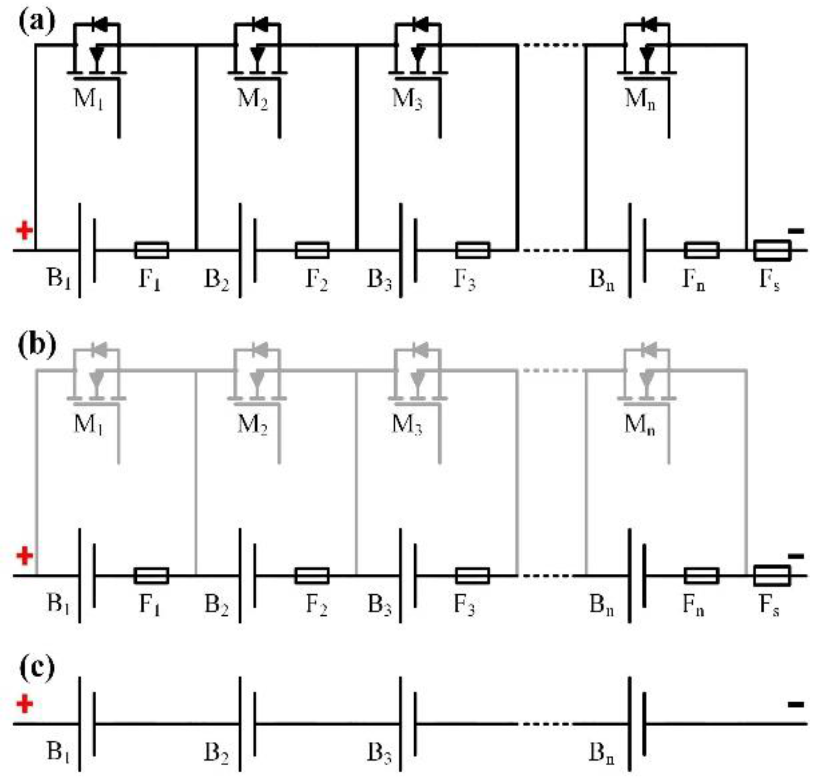
Figure 2.
The cell module of B2: (a) actual circuits; (b) equivalent circuits in balancing mode; (c) equivalent circuits in reconfiguration mode before the fuse is broken; (d) equivalent circuits in reconfiguration Mode after the fuse is broken; and (e) metallic oxide semiconductor field effect transistor (MOSFET) drive circuits.

Figure 3.
Different modes of the proposed method: (a) when B2 needs balancing; (b) when B2 and B3 need balancing; (c) when B2 and Bn need balancing; (d) when B2 needs reconfiguration; (e) when B2 and B3 need reconfiguration; and (f) when B2 and Bn need reconfiguration.
Figure 3.
Different modes of the proposed method: (a) when B2 needs balancing; (b) when B2 and B3 need balancing; (c) when B2 and Bn need balancing; (d) when B2 needs reconfiguration; (e) when B2 and B3 need reconfiguration; and (f) when B2 and Bn need reconfiguration.
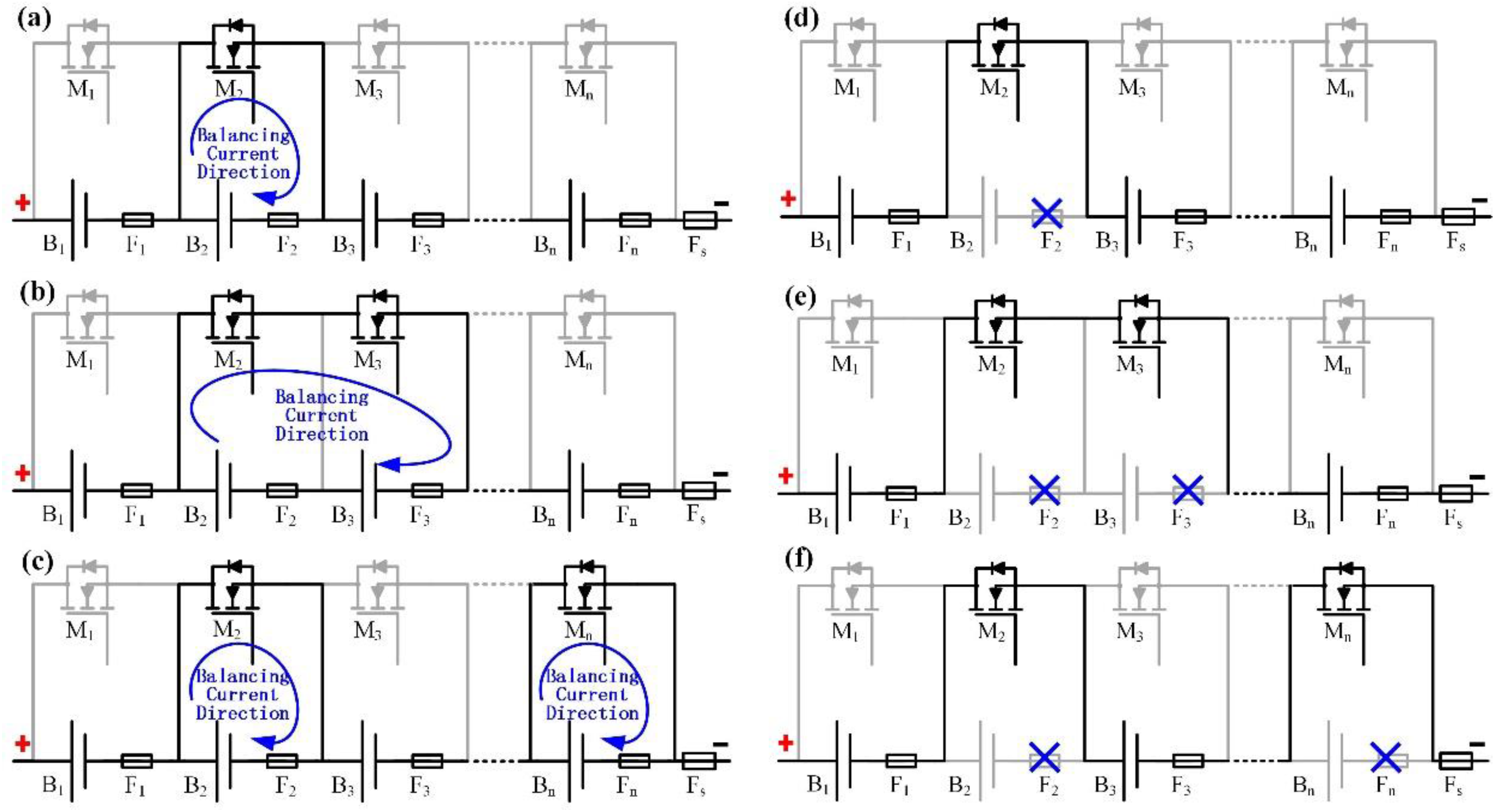
Figure 4.
Flowchart of the proposed control strategy for the reconfigurable balancing method.

Figure 5.
Experimental test workbench: (a) the configuration of the test workbench; (b) photo of the test workbench; and (c) main parts of the test workbench.
Figure 5.
Experimental test workbench: (a) the configuration of the test workbench; (b) photo of the test workbench; and (c) main parts of the test workbench.

Figure 6.
Test results for the reconfigurable balancing circuits: (a) results for the balancing mode; and (b) results for the reconfiguration mode.
Figure 6.
Test results for the reconfigurable balancing circuits: (a) results for the balancing mode; and (b) results for the reconfiguration mode.

Figure 7.
Experimental balancing performance: (a) voltage results; (b) voltage error results compared to average voltage; (c) drive signals for the switches; and (d) state of charge (SOC) results.
Figure 7.
Experimental balancing performance: (a) voltage results; (b) voltage error results compared to average voltage; (c) drive signals for the switches; and (d) state of charge (SOC) results.
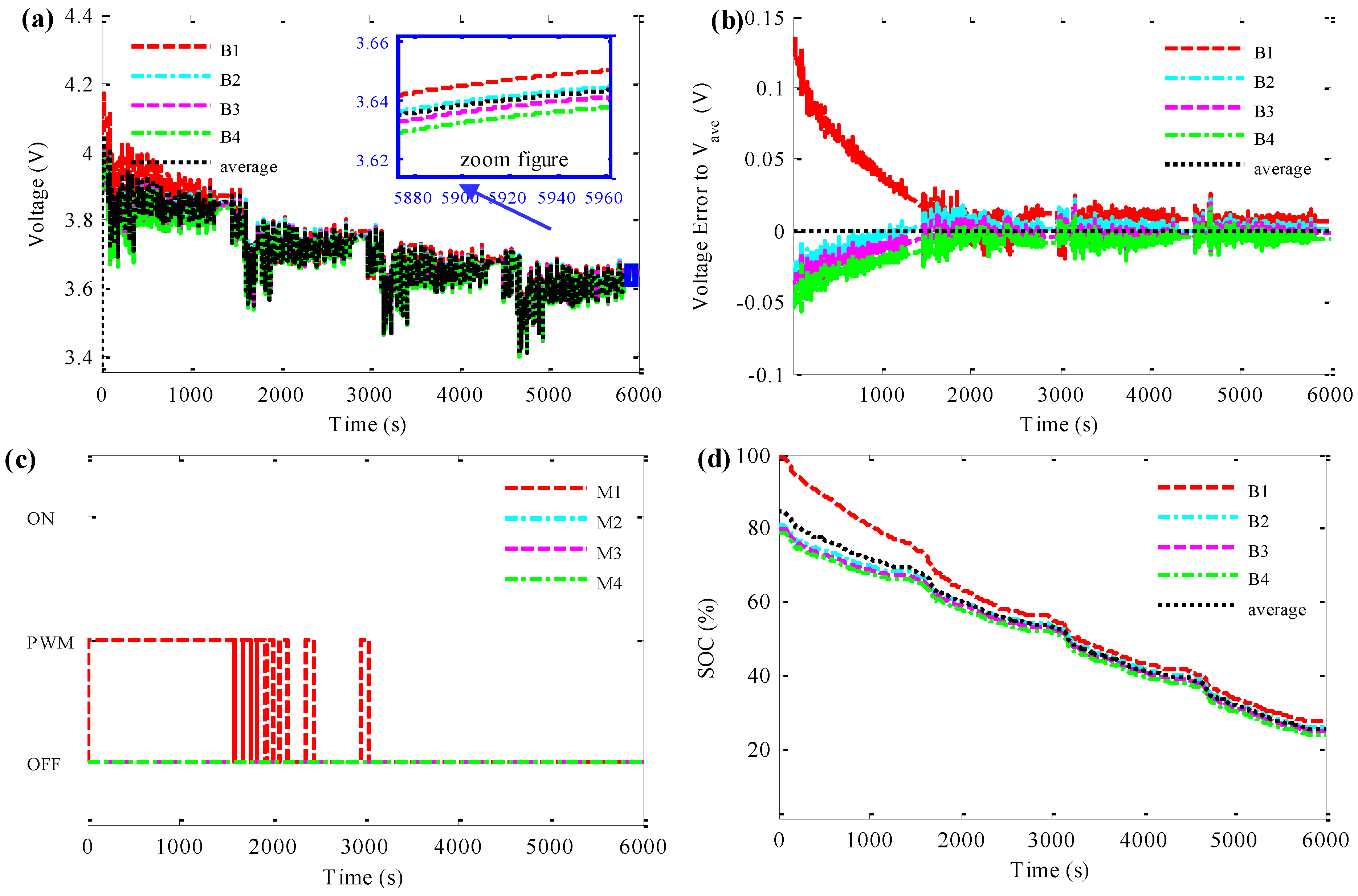
Figure 8.
Experimental balancing and reconfiguration performance: (a) voltage results; (b) voltage errors results comparing to average voltage; (c) drive signals for the switches; and (d) SOC results.
Figure 8.
Experimental balancing and reconfiguration performance: (a) voltage results; (b) voltage errors results comparing to average voltage; (c) drive signals for the switches; and (d) SOC results.

| Items | T1 | T2 | T3 | T4 | Tp |
|---|---|---|---|---|---|
| Switches | 3(n − 1) | 5n − 3 | 4n − 3 | 2n | n |
| Fuses | 0 | 0 | 0 | 0 | n |
| System Complexity | Complex | Complex | Complex | Fair | Simple |
© 2016 by the authors; licensee MDPI, Basel, Switzerland. This article is an open access article distributed under the terms and conditions of the Creative Commons Attribution (CC-BY) license (http://creativecommons.org/licenses/by/4.0/).
Share and Cite
MDPI and ACS Style
Xu, J.; Cao, B.; Wang, J. A Novel Method to Balance and Reconfigure Series-Connected Battery Strings. Energies 2016, 9, 766. https://doi.org/10.3390/en9100766
AMA Style
Xu J, Cao B, Wang J. A Novel Method to Balance and Reconfigure Series-Connected Battery Strings. Energies. 2016; 9(10):766. https://doi.org/10.3390/en9100766
Chicago/Turabian StyleXu, Jun, Binggang Cao, and Junping Wang. 2016. "A Novel Method to Balance and Reconfigure Series-Connected Battery Strings" Energies 9, no. 10: 766. https://doi.org/10.3390/en9100766
Note that from the first issue of 2016, this journal uses article numbers instead of page numbers. See further details here.